EP1756548B1 - Biosensor using whispering gallery modes in microspheres - Google Patents
Biosensor using whispering gallery modes in microspheres Download PDFInfo
- Publication number
- EP1756548B1 EP1756548B1 EP05742019.2A EP05742019A EP1756548B1 EP 1756548 B1 EP1756548 B1 EP 1756548B1 EP 05742019 A EP05742019 A EP 05742019A EP 1756548 B1 EP1756548 B1 EP 1756548B1
- Authority
- EP
- European Patent Office
- Prior art keywords
- particle
- microspheroidal
- wgm
- particles
- profile
- Prior art date
- Legal status (The legal status is an assumption and is not a legal conclusion. Google has not performed a legal analysis and makes no representation as to the accuracy of the status listed.)
- Expired - Lifetime
Links
Images



Classifications
-
- G—PHYSICS
- G01—MEASURING; TESTING
- G01N—INVESTIGATING OR ANALYSING MATERIALS BY DETERMINING THEIR CHEMICAL OR PHYSICAL PROPERTIES
- G01N21/00—Investigating or analysing materials by the use of optical means, i.e. using sub-millimetre waves, infrared, visible or ultraviolet light
- G01N21/62—Systems in which the material investigated is excited whereby it emits light or causes a change in wavelength of the incident light
- G01N21/63—Systems in which the material investigated is excited whereby it emits light or causes a change in wavelength of the incident light optically excited
- G01N21/64—Fluorescence; Phosphorescence
- G01N21/6486—Measuring fluorescence of biological material, e.g. DNA, RNA, cells
-
- B—PERFORMING OPERATIONS; TRANSPORTING
- B82—NANOTECHNOLOGY
- B82Y—SPECIFIC USES OR APPLICATIONS OF NANOSTRUCTURES; MEASUREMENT OR ANALYSIS OF NANOSTRUCTURES; MANUFACTURE OR TREATMENT OF NANOSTRUCTURES
- B82Y10/00—Nanotechnology for information processing, storage or transmission, e.g. quantum computing or single electron logic
-
- B—PERFORMING OPERATIONS; TRANSPORTING
- B82—NANOTECHNOLOGY
- B82Y—SPECIFIC USES OR APPLICATIONS OF NANOSTRUCTURES; MEASUREMENT OR ANALYSIS OF NANOSTRUCTURES; MANUFACTURE OR TREATMENT OF NANOSTRUCTURES
- B82Y20/00—Nanooptics, e.g. quantum optics or photonic crystals
-
- G—PHYSICS
- G01—MEASURING; TESTING
- G01N—INVESTIGATING OR ANALYSING MATERIALS BY DETERMINING THEIR CHEMICAL OR PHYSICAL PROPERTIES
- G01N21/00—Investigating or analysing materials by the use of optical means, i.e. using sub-millimetre waves, infrared, visible or ultraviolet light
- G01N21/75—Systems in which material is subjected to a chemical reaction, the progress or the result of the reaction being investigated
- G01N21/77—Systems in which material is subjected to a chemical reaction, the progress or the result of the reaction being investigated by observing the effect on a chemical indicator
- G01N21/7703—Systems in which material is subjected to a chemical reaction, the progress or the result of the reaction being investigated by observing the effect on a chemical indicator using reagent-clad optical fibres or optical waveguides
- G01N21/7746—Systems in which material is subjected to a chemical reaction, the progress or the result of the reaction being investigated by observing the effect on a chemical indicator using reagent-clad optical fibres or optical waveguides the waveguide coupled to a cavity resonator
-
- G—PHYSICS
- G01—MEASURING; TESTING
- G01N—INVESTIGATING OR ANALYSING MATERIALS BY DETERMINING THEIR CHEMICAL OR PHYSICAL PROPERTIES
- G01N33/00—Investigating or analysing materials by specific methods not covered by groups G01N1/00 - G01N31/00
- G01N33/48—Biological material, e.g. blood, urine; Haemocytometers
- G01N33/50—Chemical analysis of biological material, e.g. blood, urine; Testing involving biospecific ligand binding methods; Immunological testing
- G01N33/53—Immunoassay; Biospecific binding assay; Materials therefor
- G01N33/543—Immunoassay; Biospecific binding assay; Materials therefor with an insoluble carrier for immobilising immunochemicals
- G01N33/54313—Immunoassay; Biospecific binding assay; Materials therefor with an insoluble carrier for immobilising immunochemicals the carrier being characterised by its particulate form
- G01N33/54346—Nanoparticles
Definitions
- the present invention relates generally to the field of analyte detection. More particularly, the present invention relates to the use of changes in the Whispering Gallery Mode (WGM) profiles of microspheroidal particles induced by the analyte binding to an immobilized binding partner on the particle to thereby detect the presence of the analyte.
- WGM Whispering Gallery Mode
- the present invention further relates to multiplexing protocols and to analytes detected by the WGM profile changes.
- gene-chips provide a means for high throughput nucleic acid analysis using oligonucleotide arrays immobilized to slides.
- this technology is dependent on the labeling of at least one of the molecules.
- SPR detects a limit of ⁇ 10 pg.mm -2 mass loading ( Karlsson and Stahlberg, Anal Biochem 228:274-280, 1995 ) and allows real-time detection of biomolecular interactions.
- SPR requires specific and expensive instrumentation and the ability for multiplexed measurements is limited.
- the present invention provides reagents and methods for, inter alia, the detection of interactions between analytes and their binding partners without need for labeling of either molecule.
- WO 02/13337 and US 2002/0172457 disclose methods of detecting an analyte in a sample, comprising contacting a set of microspheres with the sample, wherein each microsphere comprises an immobilized binding partner of said analyte and has a defined Whispering Gallery Mode profile, and illuminating said sample, wherein binding of the analyte to the binding partner causes a spectral shift in one or more peaks of WGM profile of the transmitted illumination light.
- US 6,583,399 discloses an optically based resonating sensor useful for detecting and discriminating specified substances present in the environment, wherein the optical resonator may comprise microspheres.
- the present invention provides methods and reagents for, inter alia, detecting molecules in a sample. These molecules are referred to herein as analytes.
- the presence or structure of the analytes need not be known and hence the subject method is ideal for detecting hitherto unknown binding partners of orphan receptors and potential modulators of nucleic acid expression or protein including enzyme activity, folding, antigenicity or function.
- the methods of the present invention are predicated, in part, on the phenomenon that optically detectable labels embedded within or onto a microspheroidal particle will display a distinctive Whispering Gallery Mode (WGM) profile.
- WGM Whispering Gallery Mode
- Reference to "optically detectable” includes reference to detection by spectrometric means. When a target analyte interacts with a binding partner immobilized to the microspheroidal particle, the WGM profile changes enabling very sensitive detection of even rare binding events.
- WGMs allow only certain wavelengths of light to be emitted from the particle.
- the result of this phenomenon is that the usual broad emission (10-100nm wide) bands from, for example, a fluorophore become constrained and appear as a series of sharp peaks corresponding effectively to standing mode patterns of light within the particle.
- the WGM profile is extremely sensitive to changes at the surface of the microspheroidal particle and that the WGM profile changes when the microspheroidal particle interacts with analytes or molecules within its environment.
- the invention is directed to a method of detecting an analyte as defined in claim 1, said method comprising contacting a set of microspheroidal particles with a sample putatively comprising said analyte, wherein each particle within the set of microspheroidal particles comprises an immobilized binding partner of said analyte and wherein the particle set has a defined Whispering Gallery Mode (WGM) profile, wherein binding of said analyte to said immobilized binding partner results in a change in said WGM profile indicated by a spectral shift in one or more peaks in the WGM profile of said set of microspheroidal particles which is indicative of the presence of said analyte, and detecting said binding of analyte and binding partner by detecting said spectral shift in one or more peaks in said WGM profile, wherein each particle within said set of microspheroidal particles comprises a quantum dot as an optically detectable label and emission from said optically detectable label establishes said WGM profile.
- the methods of the present invention may be applied to detect modulation in the WGM profile of a mierospheroidal particle wherein said modulation results from detection of binding or other association of molecules in a sample to potential binding particles immobilized to the surface of the microspheroidal particle. Detection of binding reactions between an analyte and its binding partner based on sensitive changes in WGM profiles enables the identification and isolation of the analytes.
- a feature of the present invention is that the microspheroidal particles may be excited with a wide range of light sources, facilitating measurement in many different WGM profiles.
- the microspheroidal particle may be immobilized to a solid support, for example, a solid support may include a microscope slide.
- the present invention provides a microspheroidal particle comprising a latex or silica particle which is 1 ⁇ m to 100 ⁇ m in diameter, labeled with a quantum dot, the particle further comprising a putative binding partner of an analyte to be detected.
- the optically detectable label is detectable at visible wavelengths and the microspheroidal particle exhibits one or more WGM profiles.
- One or more of the WGM profiles of the microspheroidal particle detectably modulates when analytes interacts with the immobilized binding partner on the particle. Any such change in WGM profile is indicative of the presence of an analyte which has bound to its binding partner.
- analytes and binding partners include chemical molecules, nucleic acid molecules, proteins, lipids, fatty acids and carbohydrates.
- the subject method of the present invention does not require any knowledge of the existence, presence or structure of the analyte. For example, if it is desired to find a molecule (i.e. an analyte) which interacts with an enzyme or the catalytic site of an enzyme or at or near an antigenic epitope of an enzyme or protein, then the subject method does not require knowledge of whether such an analyte exists. In that case, the microspheroidal particle will carry the target binding partner at or near its surface and changes in WGM profiles used to detect an analyte in a sample such as a combinational library, chemical library or natural product source (e.g. environmental sample, serum, plasma or biological extract) which interacts with the target binding partner.
- a sample such as a combinational library, chemical library or natural product source (e.g. environmental sample, serum, plasma or biological extract) which interacts with the target binding partner.
- Multiplexing is enabled by incorporating multiple sets of microspheroidal particles wherein each set comprises particles of different sizes and/or labeled with different fluorochromes and/or different target binding partners.
- the present invention provides methods, inter alia, for detecting a molecule referred to herein as an analyte capable of entering into a binding interaction with another molecule referred to as its binding partner immobilized to the surface of a microspheroidal particle labeled with an optically detectable label which confers on the particle a defined WGM profile.
- Reference to "optically detectable” includes reference to detection by spectrometric means.
- An interaction between the analyte and the binding partner induces a change by the WGM profile.
- the methods described herein may be used for detecting analytes in samples and interactions between analytes. Importantly, neither the analyte nor its binding partner require a label.
- the interaction induces a change in the WGM profile of the microspheroidal particle.
- the methods of the present invention are predicated, in part, on the phenomenon that fluorescence emitters embedded within or onto a microspheroidal particle establish defined WGM profiles.
- the microspheroidal particles may be excited by a wide range of light sources. This facilitates measurement in many different configurations and facilitates multiplexing.
- WGMs allow only certain wavelengths of light to be emitted from a particle.
- the result of this phenomenon is that the usual broad emission (10-100nm wide) bands from a fluorophore becomes constrained and appears as a series of sharp peaks corresponding effectively to standing mode patterns of light within the particle.
- the WGM profile is extremely sensitive to interactions or associations with the surface of a the microspheroidal particle. Hence, even rare binding events can be detected due to the change in WGM profile.
- a peak or a profile includes a single peak or profile as well as two or more peaks or profile; a “microspheroidal particle” includes a single particle as well as two or more particles; and so forth.
- the present invention contemplates a method of detecting an analyte as defined in claim 1, said method comprising contacting at least one set of microspheroidal particles with a sample putatively comprising said analyte, wherein each particle within a set of microspheroidal particles comprises a quantum dot as an optically detectable label and an immobilized putative binding partner of said analyte wherein each particle set has a defined Whispering Gallery Mode (WGM) profile, wherein binding of said analyte to said immobilized binding partner results in a spectral shift in one or more peaks in said WGM profile of said at least one set of microspheroidal particles which is indicative of the presence of said analyte.
- WGM Whispering Gallery Mode
- Microspheroidal particles contemplated by the present invention include particles comprising any material, homogenous or otherwise which can produce one or more WGM profiles based on its optically detectable label. As will be evident to those of skill in the art, almost any material, homogenous or otherwise may be used for the microspheroidal particle.
- the microspheroidal particles contemplated herein may also comprise more than one substance, and as such may comprise shells, alloys or mixtures of organic and/or inorganic substances. It is advantageous for quantification of the data generated by the methods of the present invention if the microspheroidal particle comprises a substantially homogenous material with an isotropic refractive index and which is also non-absorbing (other than the optically detectable label, which is further described below).
- Particularly useful materials which may be used in accordance with the present invention and which represent specific embodiments of the present invention include materials selected from the list consisting of: silica (for example: quartz or glass), latex, titania, tin dioxide, yttria, alumina, and other binary metal oxides (such as ZnO), perovskites and other piezoelectric metal oxides (such as BaTiO 3 ), ZnS, sucrose, agarose and other polymeric beads.
- the "particle” and/or "microspheroidal particle” comprises silica.
- the "particles" and “microspheroidal particles” of the present invention are substantially spherical or spheroidal or comprise a "microsphere”.
- the particles of the present invention may be referred to as "microspheroids" the actual size of the microspheroidal particle depends on a variety of factors and the particles may or may not actually comprise measurements in the micrometer range.
- the microspheroidal particles of the present invention comprise a diameter (or equivalent measurement in a non-spheroidal particle) of about 1 ⁇ m to about 100 ⁇ m, including 1 ⁇ m, 2 ⁇ m, 3 ⁇ m, 4 ⁇ m, 5 ⁇ m, 6 ⁇ m, 7 ⁇ m, 8 ⁇ m, 9 ⁇ m, 10 ⁇ m, 11 ⁇ m, 12 ⁇ m, 13 ⁇ m, 14 ⁇ m, 15 ⁇ m, 16 ⁇ m, 17 ⁇ m, 18 ⁇ m, 19 ⁇ m, 20 ⁇ m, 21 ⁇ m, 22 ⁇ m, 23 ⁇ m, 24 ⁇ m, 25 ⁇ m, 26 ⁇ m, 27 ⁇ m, 28 ⁇ m, 29 ⁇ m, 30 ⁇ m, 31 ⁇ m, 32 ⁇ m, 33 ⁇ m, 34 ⁇ m, 35 ⁇ m, 36 ⁇ m, 37 ⁇ m, 38 ⁇ m, 39 ⁇ m
- fractions between 1 and 2 ⁇ m include 1.05, 1.1, 1.15, 1.2, 1.25, 1.3, 1.35, 1.4, 1.45, 1.5, 1.55, 1.6, 1.65, 1.7, 1.75, 1.8, 1.85, 1.9, 1.95 or 2.0.
- the microspheroidal particles are microspheres.
- a set of microspheroidal particles including a set of microspheres includes a multiplicity (i.e. two or more) particles or microspheres having a common label or size or immobilized binding partner.
- the term "optically detectable label” refers to any molecule, atom or ion which emits fluorescence or phosphorescence.
- the optically detectable label may be chosen to emit at any wavelength at which WGM profile may be easily resolved. This depends on the ratio of the wavelength of the emission to the particle radius. Given that the sphere radius is arbitrary, the emission may be suitably chosen from the ultraviolet (wavelength range of about 350nm to about 3nm), visible (wavelength range of about 350nm to about 800nm, near infrared (NIR) (wavelength range of about 800nm to about 1500nm) and/or infrared (IR) (wavelength range of about 1500nm to about 10 ⁇ m) ranges. However, due to the ease of detection, in one particularly preferred embodiment, the optically detectable label is detectable in the visible wavelength range.
- the optically detectable label may be an optically detectable label which emits visible radiation in response to Infrared excitation.
- optically detectable labels are also referred to herein as "upconverters”.
- an exemplary method of detecting an analyte may comprise contacting at least one set of microspheroidal particles with a sample putatively comprising said analyte, wherein each particle within a set of microspheroidal particles comprises a label with emits visible radiation in response to infrared excitation and an immobilized putative binding partner of said analyte wherein each particle set has a defined Whispering Gallery Mode (WGM) profile, wherein binding of said analyte to said immobilized binding partner results in a change in said WGM profile of said at least one set of microspheroidal particles which is indicative of the presence of said analyte.
- WGM Whispering Gallery Mode
- the only constraint on the optically detectable label is that the emission in the chosen label should result in cavity mode emission.
- the optically detectable label comprises a quantum dot.
- the scattered light from small metal particles may be used as an optically detectable label.
- optically detectable label which may be used in accordance with the present invention is to embed fluorescent particles on or in the microspheroidal particle.
- These optically detectable label particles may be so small that their properties and emission become size dependent.
- Such small optically detectable label particles are referred to in the art as semiconductor nanoparticles, quantum dots, quantum wires, quantum rods or nanocrystals or Q-particles.
- quantum dot or “QD” is to be understood to encompass all such particles.
- optically detectable labels comprising QDs may comprise approximately spherical or spheroidal particles, or coated spherical or spheroidal particles.
- QD should not be considered in any way to be limited to a spherical, spheroidal, circular, cylindrical or any other morphology of a "dot".
- QDs may also comprise other morphologies including, inter alia, rod-like, ellipsoidal, or coated rod-like or ellipsoidal particles.
- QDs consist of a nanometer-scale crystalline core of semiconductor material; biologically active versions are typically surrounded by a protective shell and external coat.
- QDs may comprise semiconductor crystallites which are about 2 nm to about 30 nm in diameter (e.g. 2, 3, 4, 5, 6, 7, 8, 9, 10, 11, 12, 13, 14, 15, 16, 17, 18, 19, 20, 21, 22, 23, 24, 25, 26, 27, 28, 29 or 30 nm) and may contain approximately 50-500,000 atoms within the crystal, including luminescent crystals comprising materials such as ZnS, ZnSe, ZnTe, CdS, CdSe, CdTe, PbS, PbSe, PbTe, HgS, HgSe, HgTe, Si, ZnO.
- QDs fluoresce with a broad absorption spectrum and a narrow emission spectrum. Unlike some other fluorophores, which have distinct absorption spectra, QDs absorb light over a wide spectral range, which allows quantum dots to be excited with a range of light sources, such as lasers, arc lamps, or LEDs. Furthermore, a collection of different QDs can be used in multiplex applications using only a single excitation source. However, the emission spectra for each dot is typically very narrow, in the order of about 30 nm, the exact color depending on the particle's diameter and composition. Furthermore, the narrow emission spectrum of QDs permits spectral resolution of adjacent dots. In addition to the benefits above, QDs are also relatively photostable, even during intense excitation, and are brighter than fluorophores.
- the present invention encompasses the use of different sized QDs in order to optimise the wavelengths at which WGM profiles may be generated in a microspheroidal particle.
- the present invention contemplates QDs which are treated with procedures such as thermal treatment, surface modification, alloying, surface passivation or capping with surface coatings to enable the QD to emit with high quantum yield and to improve the photostability for long periods of time.
- QDs are also commercially available from companies such as Quantum Dot Corp. (QDC), which produces QDs such as the Qdot [Trade Mark] 605 streptavidin conjugate, containing a cadmium-selenide core that emits at 605 nm. Qdot conjugates that emit at 525, 565, 585, and 655 nm are also available.
- QDC Quantum Dot Corp.
- QDs such as the Qdot [Trade Mark] 605 streptavidin conjugate, containing a cadmium-selenide core that emits at 605 nm.
- Qdot conjugates that emit at 525, 565, 585, and 655 nm are also available.
- the present invention is not limited in any way by the particular composition of the QD (or any other optically detectable label) and any QD (commercial or otherwise) may be compatible with the present invention.
- fluorescent dyes which are available in the art which may be used as fluorophores in exemplary methods that do not form part of the claimed invention.
- An important property of a fluorescent dye or other fluorophore, which determines it's potential for use is the excitation wavelength of the fluorophore; it must match the available wavelengths of the light source.
- fluorescent dyes and other fluorophores will be familiar to those of skill in the art, and the choice of fluorescent marker in no way limits the subject invention.
- the fluorescent markers are selected from: Alexa Fluor dyes; BoDipy dyes, including BoDipy 630/650 and BoDipy 650/665; Cy dyes, particularly Cy3, Cy5 and Cy 5.5; 6-FAM (Fluorescein); Fluorescein dT; Hexachlorofluorescein (HEX); 6-carboxy-4', 5'-dichloro-2', 7'- dimethoxyfluorescein (JOE); Oregon green dyes, including 488-X and 514; Rhodamine dyes, including Rhodamine Green, Rhodamine Red and ROX; Carboxytetramethylrhodamine (TAMRA); Tetrachlorofluorescein (TET); and Texas Red.
- Alexa Fluor dyes BoDipy dyes, including BoDipy 630/650 and BoDipy 650/665
- Cy dyes particularly Cy3, Cy5 and Cy 5.5
- 6-FAM Fluorescein
- Two dyeing techniques are commonly used to fluorescently label microspheroidal particles internal dyeing and external dyeing (surface-labeling).
- the two techniques produce particles with unique properties, each beneficial for different applications.
- Internal dyeing produces extremely stable particles with typically narrow fluorescence emissions. These particles often display a greater resistance to photobleaching.
- surface groups are available for use in conjugating ligands (proteins, antibodies, nucleic acids, etc.) to the surface of the bead. For this reason, internally labeled beads are typically used in analyte-detection and immunoassay applications.
- Surface-labeling involves conjugation of the fluorophore to the microspheroidal particle surface.
- the fluorophores are on the surface of the particle, they are able to interact with their environment just as the fluorophores on a stained cell.
- the result is a particle standard that exhibits the same excitation and emission properties as stained cell samples, under a variety of different conditions, such as the presence of contaminants or changes in pH.
- the "environmentally responsive" nature of surface-labeled particles makes them ideally suited for mimicking biological samples. Externally labeled particles are frequently used as controls and standards in a number of applications utilizing fluorescence detection.
- the present invention contemplates the association of a particle with a fluorescent label via any means.
- phosphorescent particles are used interchangeably herein. What constitutes a phosphorescent optically detectable label would be readily understood by one of skill in the art. However, by way of example, which in no way limits the invention, suitable phosphors include small particles of ZnS, ZnS:Cu, Eu oxide and other phosphors used in display devices.
- a optically detectable label comprising a "doped particle” may include a particle which comprises occluded amounts of one or more rare earth ions, such as Eu, Y, Yb, Sm and the like.
- optically detectable label should be understood to also encompass multiple optically detectable labels, mixtures of optically detectable labels, coated nanocrystals, alloys and other complex mixtures that would be evident to the skilled artisan.
- optically detectable labels on microspheroidal particles is to be considered as being within the scope of the methods and reagents described herein.
- the emission of any particular label depends on the distribution of the label in the microspheroidal particle, the type of label and the concentration of label.
- the methods of the present invention are still practicable irrespective of whether the optically detectable label is at the surface of the microspheroidal particle, present as a shell within the microspheroidal particle, located at the core of the microspheroidal particle or is present in more than one of the recited locations.
- the methods of the present invention are not predicated on quenching of the emission from the optically detectable label.
- the methods of the present invention are predicated, in part, on a modulation (i.e. a change) in the WGM profile of the optically detectable label as a result of a interaction or association of an analyte with a binding partner immobilized to the surface of a microspheroidal particle.
- WGMs when dealing with electromagnetic radiation, are electromagnetic resonances that can be established when incident light interacts with a particle of higher refractive index than its surrounding medium. WGMs occur at particular resonant wavelengths of light for a given particle size, and the nature of the WGM may change with, inter alia, the size of the particle containing the WGM and the refractive indices of both the particle and the surrounding medium. Furthermore, the size of the particle can also effect the WGM established therein. WGMs are established when the incident light undergoes total internal reflection at the particle surface.
- Total internal reflection may occur at the interface between two non-absorbing media.
- TIR Total internal reflection
- a beam of light propagating in the medium of higher refractive index meets an interface at a medium of lower refractive index at an angle of incidence above a critical angle
- the light is totally reflected at the interface and propagates back into the high refractive index medium.
- the light may be reflected many times within the particle of higher refractive index.
- the light is concentrated near the circumference of the particle and can be assigned a mode number and a mode order.
- the mode number, n provides the number of wavelengths around the circumference of the particle
- the mode order, l provides the number of maxima in the radial dependence of the electromagnetic field within the particle.
- the series of peaks generated as a result of the establishment of a WGM in the microspheroidal particle of the present invention are referred to herein as "Whispering Gallery Mode Profiles" or " WGM Profiles".
- the WGM profile is extremely sensitive to both the position of the embedded optically detectable label and their concentration and spatial configuration with respect to each other. Furthermore, particle size and refractive index are also important in determining the emission wavelengths seen in a WGM profile.
- the position and amplitude of one or more peaks in a WGM profile may be strongly influenced by interactions or associations of the microspheroidal particle with molecules in a sample or external environment.
- association or binding of a molecule to a microspheroidal particle alters the effective refractive index of the microspheroidal particle altering the WGM profile generated by the microspheroidal particle.
- the refractive index of a medium is a value calculated from the ratio of the speed of light in a vacuum to that in a second medium of greater density.
- a change in "effective refractive index” may be a change in the refractive index of the complete microspheroidal particle, or a change in effective refractive index may be a change in the refractive index of a region or part of the microspheroidal particle.
- a change in the effective refractive index of a microspheroidal particle may comprise a change in the refractive index of the surface and/or periphery of the microspheroidal particle.
- the present invention contemplates a method for detecting the binding or association of a molecule to, or proximal with, the surface or sub-surface of the microspheroidal particle wherein the binding or association of the molecule to an immobilized binding partner of the molecule effects a change in the effective refractive index at the surface of the microspheroidal particle.
- a "sub-surface” includes pockets or pores surrounding the particle or which form a co-continuous interface between an internal environment of the particle and an external environment.
- the molecule or binding partner immobilized to the microspheroidal particle or the analyte in a sample refers to any chemical entity.
- chemical entities include, but are not limited to small chemical molecule; peptides, polypeptides and proteins or analogs thereof, nucleic acid molecules or analogs thereof, metal atoms or ions or compounds comprising such atoms or ions.
- nucleic acid molecules short interfering RNAs (single or double stranded) [siRNAs], interfering RNA complexes (RNAi) and DNA and RNA oligonucleotides are particularly contemplated.
- Chemical compounds include entities produced in a combinatorial library or in a chemical library.
- a biological source includes an environmental sample, organism extract, plant or animal extract, serum, urine, exudate, semen, plasma, soil sample, river or sealed sample, extraterrestrial sample, amongst other sources.
- the phrase "bound to, or otherwise associated with” refers to any process by which a molecule may be associated with a microspheroidal particle.
- Exemplary modes by which such associations may be mediated include, but are not limited to: covalent binding, hydrogen bonding, van der Waals forces, ionic bonding, metallic bonding, polar bonding and dative (covalent) bonding and the like.
- a molecule including a binding partner may also be attached to a microspheroidal particle via an agent that promotes or increases the adsorption or binding of the molecule to the surface of the microspheroidal particle, such an agent is referred to herein as a "linker".
- a linker For example, polynucleotides may be associated with a microspheroidal particle via a linker which comprises a thiol, amine or carboxyl group.
- suitable linkers include amino-terminated silanes such as amino-propyltrimethoxysilane or aminopropyltriethoxysilane.
- silanes In addition to silanes, compounds such as poly-L-lysine that non-covalently attach to surfaces such as glass and electrostatically adsorb the phosphate groups of a polynucleotide are also within the scope of the present invention. Therefore, other molecules, including other silanes, which are suitable to promote the binding or association of a polynucleotide, polypeptide or other compound to the surface of a microspheroidal particle would be readily identified by the skilled artisan, and the present invention is not limited by the choice of linker.
- nucleic acids include RNA, cDNA, genomic DNA, synthetic forms and mixed polymers, both sense and antisense strands, and may be chemically or biochemically modified or may contain non-natural or derivatized nucleotide bases, as will be readily appreciated by those skilled in the art.
- modifications include, for example, labels, methylation, substitution of one or more of the naturally occuring nucleotides with an analog (such as a morpholine ring), internucleotide modifications such as uncharged linkages (eg. methyl phosphonates, phosphotriesters, phosphoamidates, carbamates, etc.), charged linkages (eg.
- phosphorothioates phosphorodithioates, etc.
- pendent moieties eg. polypeptides
- intercalators eg. acridine, psoralen, etc.
- chelators eg. acridine, psoralen, etc.
- alkylators eg. ⁇ -anomeric nucleic acids etc.
- synthetic molecules that mimic polynucleotides in their ability to bind a designated sequence via hydrogen bonding and other chemical interactions. Such molecules are known in the art and include, for example, those in which peptide linkages substitute for phosphate linkages in the backbone of the molecule.
- microspheroidal particle further comprises DNA bound to, or otherwise associated with, the surface of the microspheroidal particle.
- the microspheroidal particle further comprises RNA or a complex of RNA (e.g. RNA - Rnase complex) bound to, or otherwise associated with, the surface of the microspheroidal particle.
- RNA e.g. RNA - Rnase complex
- the present invention contemplates that the WGM profile of the microspheroidal particle detectably modulates when a peptide, polypeptide or protein or analog thereof binds to, or otherwise associated with, the surface of the microspheroidal particle.
- the peptide, polypeptide or protein is an enzyme.
- the peptide, polypeptide or protein is an antibody.
- antibody refers to a protein of the immunoglobulin family that is capable of combining, interacting or otherwise associating with an antigen.
- An antibody is, therefore, an antigen-binding molecule.
- antigen is used herein in its broadest sense to refer to a substance that is capable of reacting with or binding to the antigen-binding site of an antibody. With reference to the present invention, an antigen also includes the idiotype of an antibody.
- immunoglobulin is used herein to refer to a protein consisting of one or more polypeptides substantially encoded by immunoglobulin genes.
- the recognized immunoglobulin molecules include the ⁇ , ⁇ , ⁇ , ⁇ (IgG 1 , IgG 2 , IgG 3 , IgG 4 ), ⁇ , ⁇ and ⁇ constant regions, light chains ( ⁇ and 1), as well as the myriad immunoglobulin variable regions.
- One form of immunoglobulin constitutes the basic structural unit of an antibody. This form is a tetramer and consists of two identical pairs of immunoglobulin chains, each pair having one light and one heavy chain.
- immunoglobulins may exist in a variety of other forms including, for example, Fv, Fab, Fab' and (Fab') 2 and chimeric antibodies and all of these variants are encompassed by the term "antibody” as used herein.
- immunoglobulins from other animals eg. birds, mammals, fish, amphibians, and reptiles
- the microspheroidal particles may comprise anti-idiotypic antibodies bound to, or otherwise associated therewith.
- anti-idiotypic antibody refers to an antibody which recognizes and binds to antigenic determinants within the variable region, for example the V H and/or V L domains, of a target antibody. These antigenic determinants within the variable region of an antibody are referred to as the "idiotype” of an antibody. Accordingly, an antibody specific for these regions is referred to as an "anti-idiotypic antibody”.
- Analogs of peptides, polypeptides and/or proteins contemplated herein include but are not limited to peptides, polypeptides or proteins comprising modification to side chains, synthetic peptides that incorporate unnatural amino acids and/or their derivatives during synthesis and the use of crosslinkers and other methods which impose conformational constraints on the subject peptide, polypeptide or protein.
- side chain modifications include modifications of amino groups such as by reductive alkylation by reaction with an aldehyde followed by reduction with NaBH 4 ; amidination with methylacetimidate; acylation with acetic anhydride; carbamoylation of amino groups with cyanate; trinitrobenzylation of amino groups with 2, 4, 6-trinitrobenzene sulphonic acid (TNBS); acylation of amino groups with succinic anhydride and tetrahydrophthalic anhydride; and pyridoxylation of lysine with pyridoxal-5-phosphate followed by reduction with NaBH 4 .
- modifications of amino groups such as by reductive alkylation by reaction with an aldehyde followed by reduction with NaBH 4 ; amidination with methylacetimidate; acylation with acetic anhydride; carbamoylation of amino groups with cyanate; trinitrobenzylation of amino groups with 2, 4, 6-trinitrobenzene sulphonic acid (TNBS); acylation of amino groups with
- the guanidine group of arginine residues may be modified by the formation of heterocyclic condensation products with reagents such as 2,3-butanedione, phenylglyoxal and glyoxal.
- the carboxyl group may be modified by carbodiimide activation via O-acylisourea formation followed by subsequent derivitization, for example, to a corresponding amide.
- Sulphydryl groups may be modified by methods such as carboxymethylation with iodoacetic acid or iodoacetamide; performic acid oxidation to cysteic acid; formation of a mixed disulphide with other thiol compounds; reaction with maleimide, maleic anhydride or other substituted maleimide; formation of mercurial derivatives using 4-chloromercuribenzoate, 4-chloromercuriphenylsulphonic acid, phenylmercury chloride, 2-chloromercuri-4-nitrophenol and other mercurials; carbamoylation with cyanate at alkaline pH.
- Tryptophan residues may be modified by, for example, oxidation with N-bromosuccinimide or alkylation of the indole ring with 2-hydroxy-5-nitrobenzyl bromide or sulphonyl halides.
- Tyrosine residues on the other hand, may be altered by nitration with tetranitromethane to form a 3-nitrotyrosine derivative.
- Modification of the imidazole ring of a histidine residue may be accomplished by alkylation with iodoacetic acid derivatives or N-carbethoxylation with diethylpyrocarbonate.
- Examples of incorporating unnatural amino acids and derivatives during peptide synthesis include, but are not limited to, use of norleucine, 4-amino butyric acid, 4-amino-3-hydroxy-5-phenylpentanoic acid, 6-aminohexanoic acid, t-butylglycine, norvaline, phenylglycine, ornithine, sarcosine, 4-amino-3-hydroxy-6-methylheptanoic acid, 2-thienyl alanine and/or D-isomers of amino acids.
- a list of unnatural amino acid, contemplated herein is shown in Table 2.
- Non-conventional amino acid Code ⁇ -aminobutyric acid Abu L-N-methylalanine Nmala ⁇ -amino- ⁇ -methylbutyrate Mgabu L-N-methylarginine Nmarg aminocyclopropane-carboxylate Cpro L-N-methylasparagine Nmasn L-N-methylaspartic acid Nmasp aminoisobutyric acid Aib L-N-methylcysteine Nmcys aminonorbornyl-carboxylate Norb L-N-methylglutamine Nmgln L-N-methylglutamic acid Nmglu cyclohexylalanine Chexa L-Nmethylhistidine Nmhis cyclopentylalanine Cpen L-N-methylisolleucine Nmile D-alanine Dal L-N-methylleucine Nmleu D-arginine Darg L-N-methyl
- peptides can be conformationally constrained by, for example, incorporation of C ⁇ and N ⁇ -methylamino acids, introduction of double bonds between C ⁇ and C ⁇ atoms of amino acids and the formation of cyclic peptides or analogs by introducing covalent bonds such as forming an amide bond between the N and C termini, between two side chains or between a side chain and the N or C terminus.
- the WGM profile of the microspheroidal particle detectably modulates when a carbohydrate molecule or analog thereof binds to, or otherwise associates with, the surface of the microspheroidal particle.
- the carbohydrate molecule is a Glycosaminoglycan (GAG) molecule or GAG-like molecule.
- GAG Glycosaminoglycan
- GAGs are ubiquitous and play pivotal roles in many of the inflammatory processes within the human body. These large molecular weight polysaccharides contribute to such processes as cancer metastasis, arthritis, transplant rejection and asthma and thus a greater understanding of these processes may lead to improved drugs for the eventual treatment of such conditions.
- GAGs one of the best known GAGs is the heparin family of sulfated polysaccharides and the anti-coagulant activity of these molecules is well understood.
- Heparin-Like GAGs are a heterogenous group of molecules ( Conrad, Heparin binding proteins. Academic Press, San Diego, 1998 ; Lander and Selleck, J Cell Biol 148(2):227-232, 2000 ). Heparin and heparan sulfate, like all HLGAGs, are long linear polysaccharides ( Sasisekharan and Venkataraman, Curr Opin Chem Biol 4(6):626-631, 2000 ; Casu, Ann NY Acad Sci 556:1-17, 1989 ; Casu, Adv Carbohydr Chem Biochem 43:51-134, 1985 ).
- glucuronic acid GlcA
- GlcN glucosamine
- Heparin is more extensively modified than heparan sulfate and most of the GlcN units are modified by a sulfate group to become N-sulfated GlcN and most GlcA units are converted to iduronic acid (IdoA) through the action of epimerase.
- HLGAGs are heterogenous since modifications to the sulfate chains are often incomplete. The result is extensive regions of intermediate modification.
- heparan sulfate chains consist of highly sulfated, structurally flexible domains rich in 2-O-sulfated IdoA alternating with regions of low sulfation consisting predominantly of N-acetyl GlcN and GlcA, which are a rigid structure.
- the sulfation patterns of HLGAGs are complex especially with respect to the positioning of 6-O- sulfates. Consequently, not all HLGAG molecules are identical. It is the sulfation pattern which largely determines the protein binding characteristics of a particular HLGAG.
- Anti-thrombin III binds to a unique pentasaccharide sequence displaying a particular arrangement of sulfate groups and the heparin pentasaccharide binds to a specific site on the anti-thrombin III protein ( Whisstock et al. J Mol Biol 301:1287-1305, 2000 ).
- FGF-2 Basic fibroblast-derived growth factor
- HGF hepatocyte growth factor
- FGF-2 recognizes a motif containing a single IdoA 2-O-sulfate in a defined position, whereas for HGF, the positioning of the GlcN 6-O-sulfate groups are critical.
- Some heparin molecules within a preparation will carry both the anti-thrombin III binding pentasaccharide and the FGF-2 binding motif, whereas others will carry the HGF binding motif and the FGF-2 motif and not the anti-thrombin III binding pentasaccharide. Indeed, on average only one third of the molecules within a preparation of heparin carry the anti-thrombin III binding pentasaccharide (Conrad, 1998, supra).
- GAG-like molecules may also be derived from non-mammalian sources.
- the capsular polysaccharide from E. coli K5 is composed of an alternate ⁇ -N-acetyl glucosamine ( ⁇ -GlcNAc) and ⁇ -glucuronic acid ( ⁇ -GlcA) units and contains no sulfate or other charged groups.
- the heparin backbone consists of the following motif ⁇ -GlcNAc, ⁇ -GlcA, ⁇ -GlcNAc, ⁇ -iduronic acid ( ⁇ -IdoA) with varying degrees of sulfation.
- the only difference between GlcA and IdoA is the configuration of the carboxylic acid group at C-5, thus the heparin backbone and the E. coli K5 backbone are extremely similar in structure.
- a detectable change in the WGM profile of the microspheroidal particle, relative an initial WGM profile, is indicative of binding or interaction between the molecule and the analyte binding partner of the molecule.
- a detectable change in the WGM profile comprises a spectral shift in one or more peaks in the WGM profile.
- the detectable change may comprise either a red-shift or blue-shift of one or more peaks in one WGM profile relative to another WGM profile.
- red-shift refers to the shifting of the point of maximum amplitude of one or more peaks in a WGM profile to a longer wavelength. Despite the name “red”, a red-shift may occur in any part of the electromagnetic spectrum and is not limited to visible light. As used herein, the term “red-shift” includes any shifting of a peak to a longer wavelength. Conversely, the term “blue-shift” refers to any movement of a peak to a shorter wavelength.
- the red-shift or blue-shift of a peak in a WGM profile typically comprises a change in the wavelength of the maximum amplitude of the peak of approximately 1 to 100 nm.
- Reference to 1 to 100nm includes wavelengths of 1, 2, 3, 4, 5, 6, 7, 8, 9, 10, 11, 12, 13, 14, 15, 16, 17, 18, 19, 20, 21, 22, 23, 24, 25, 26, 27, 28, 29, 30, 31, 32, 33, 34, 35, 36, 37, 38, 39, 40, 41, 42, 43, 44, 45, 46, 47, 48, 49, 50, 51, 52, 53, 54, 55, 56, 57, 58, 59, 60, 61, 62, 63, 64, 65, 66, 67, 68, 69, 70, 71, 72, 73, 74, 75, 76, 77, 78, 79, 80, 81, 82, 83, 84, 85, 86, 87, 88, 89, 90, 91, 92, 93, 94, 95, 96, 97
- the red-shift or blue-shift of a peak in a WGM profile comprises a change in the wavelength of the maximum amplitude of the peak of approximately 1 to 20 nm, which includes wavelengths of 1, 2, 3, 4, 5, 6, 7, 8, 9, 10, 11, 12, 13, 14, 15, 16, 17, 18, 19 and 20 nm.
- the invention also contemplates equivalent and/or proportionate red-shifts and blue-shifts in other regions of the electromagnetic spectrum.
- a WGM profile of a microspheroidal particle as described herein may be ascertained using any convenient method that would be evident to one of skill in the art. Essentially any detection method which can detect one or more wavelengths of electromagnetic radiation may be used to detect a WGM profile.
- the detection means is sufficiently sensitive such that it can differentiate peaks in the WGM profile, more preferably, the detection means can differentiate between two peaks which are at least 1, 2, 3, 4, 5, 6, 7, 8, 9, 10, 11, 12, 13, 14, 15, 16, 17, 18, 19, 20, 21, 22, 23, 24, 25, 26, 27, 28, 29, 30, 31, 32, 33, 34, 35, 36, 37, 38, 39, 40, 41, 42, 43, 44, 45, 46, 47, 48, 49, 50, 51, 52, 53, 54, 55, 56, 57, 58, 59, 60, 61, 62, 63, 64, 65, 66, 67, 68, 69, 70, 71, 72, 73, 74, 75, 76, 77, 78, 79, 80, 81, 82, 83, 84, 85, 86, 87, 88, 89, 90, 91, 92, 93, 94, 95, 96, 97, 98, 99 and/or 100 nm apart.
- Particularly convenient means which may be used
- confocal microscope includes within its scope, laser scanning confocal microscopes (LSCM) and multiphoton confocal microscopes.
- the microspheroidal particle may be immobilized to a solid support.
- solid support refers to any solid matrix onto which a microspheroidal particle may be immobilized.
- the solid support comprises a solid support which allows the WGM profile of the microspheroidal particle immobilized thereto to be detected.
- preferable solid supports are those which may be used to immobilize a microspheroidal particle for analysis using a confocal microscope.
- the solid support is a microscope slide.
- the method of the present invention can be used for the following applications: environmental monitoring, such as water quality (Legionella, Giardia, Cryptosporidium, at the source) and point of care diagnostics, airborne pathogens and toxins, protein:protein interaction screening, protein:carbohydrate interaction screening and drug screening, and screening of libraries of small molecules.
- environmental monitoring such as water quality (Legionella, Giardia, Cryptosporidium, at the source) and point of care diagnostics, airborne pathogens and toxins, protein:protein interaction screening, protein:carbohydrate interaction screening and drug screening, and screening of libraries of small molecules.
- Multiplexing is enabled due to the ability to have two or more sets of microspheroidal particles.
- the particles in any one set may have a common optically detectable label and/or a common size and/or a common immobilized binding particle.
- multiple analytes may be detected using a multiplicity of sets of microspheroidal particles.
- microspheroidal particles may be prepared by overlaying commercial beads of any desired composition or size with quantum dots. For more robust materials, they should be overcoated with another silica layer to minimize interactions with the medium or adsorbates.
- 0.1g of five micron diameter commercial silica beads were placed in 20 ml 2-propanol and 20 microlitres of either mercaptopropylsilane (MPS) or aminopropylsilane (APS) was added.
- MPS mercaptopropylsilane
- APS aminopropylsilane
- the solution was refluxed at 80°C to allow chemisorption of the MPS or APS, which led to the creation of mercaptan or amino groups on the bead surface. Excess MPS or APS was removed by centrifugation.
- the beads can also be activated by adsorbing a cationic polymer.
- adsorbing a cationic polymer For example without restriction and to illustrate the method, 0.1g of silica beads were mixed with 20mL of an aqueous PEI (poly(ethylene imine) solution (1g/L, 0.5M NaCl). After reacting for one hour, the solution was centrifuged to remove the excess polymer and resuspended in pure water. This procedure was repeated 3 times.
- PEI poly(ethylene imine) solution
- QDs were adsorbed onto the APS or PEI coated beads by adding a suspension of QDs in chloroform to a suspension of the beads in dry 2-propanol. The amount added was such as to coat the beads with about 10 monolayers. The beads and QDs were equilibrated for 10 minutes in a rotation tumbler. Then, the coated beads were separated by centrifugation.
- the QD labeled beads can be further stabilized by coating with more silica. This was done in two ways:
- the second procedure involved direct silica growth in ethanol without a preliminary deposition step in water. This consists of adsorption of PVP and then growth of silica. Enough PVP (MW 30,000) was added to provide 60PVP molecules per nm 2 of surface, by dissolving it in chloroform:2-propanol (9:1). This was immediately added to the microspheres, the mixture was sonicated and allowed to react overnight under stirring.
- microspheres were centrifuged (5 sec at 3800rpm for 5micron silica) and re-dispersed in 2-propanol (first time). NH 3 (4.2%) followed by TEOS (10vol% in 2-propanol) was added with stirring and left to deposit over 12 hours.
- FIG. 1 A schematic showing the procedure for producing QD labeled microspheroidal particles is shown in Figure 1 .
- This generic protocol allows the preparation of photostable, silica microspheres of any practical size from 1 micron up to 100 microns, labeled with one or more different nanoparticles with different emission properties.
- Q-Sand beads were conjugated to DNA, forming a complex with a Q-Sand bead and immobilized 48-mer DNA.
- the fifth base position of the 48-mer was a thymidine base with an incorporated amine. This amine was used to label the DNA with a BODIPY•630/650 NHS ester using a standard condensation reaction.
- the WGM profile for the Q-Sand bead conjugated to the 48-mer DNA is shown in Figure 5 , panel a.
- Panel b of Figure 5 shows the WGM profile of the Q-Sand bead of panel a conjugated to a ⁇ -Transprobe DNA which hybridizes to bases 6-24 of the DNA conjugated to the Q-Sand bead.
- the resulting WGM profile, as seen in panel b of Figure 5 was a shift of approximately 2.4nm for all peaks.
- the Q-factor (the measure of the quality of the microresonator) reduction was approximately 5X.
- silica microspheroidal particles can be done in the same way used for the initial silica microspheroidal particles by refluxing the QD-silica microspheroidal particles in 2-propanol containing MPS or APS or other silane to activate the surface and add functional groups which react with the target bioadsorbate.
- microspheres labeled with orange QDs emitting at 560 nm and overcoated with 10 nm silica were treated with MPS, centrifuged and washed.
- the microspheres were allowed to react in water with the conjugate, such as a nucleic acid, polypeptide, antibody, carbohydrate or the like for about 1 hour. They were then centrifuged and washed to yield Bioactive QD Microspheres (BQDM).
- Microspheroidal particles of different sizes were produced using the methods described herein. WGM profiles of each of the different particle sizes were determined using a confocal microscope.
- the WGM profile exhibited by each of the different sized particles changes with the radius of the microspheroidal particle.
- QD labeled microspheroidal particles comprising different molecules bound to their surface were produced using the methods described herein.
- WGM profiles of each of the different microspheroidal particles were determined using a confocal microscope.
- QD refers to a QD labeled microspheroidal particle with no compound bound to the surface
- PSS refers to a microspheroidal particle comprising bound polystyrene sulfonate (PSS)
- PVP refers to microspheroidal particle with an adsorbed monolayer of polyvinyl pyrrolidone (PVP).
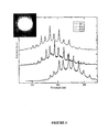
- the QD labeled microspheroidal particles are sensitive to the binding of a compound to their surface. Furthermore, the WGM profile shift observed also appears sensitive to the nature of the compound binding to the surface.
- Silica microspheres with functional surface sulfhydryl groups are conjugated, via a 5' acrydite molecule, to single stranded oligonucletides, which have previously been labeled with a fluorescent dye.
- microspheres with attached, labeled oligonucleotide are then hybridised to complimentary or unrelated oligonucleotides or PCR products.
- the hybridised and unhybridised microspheres are extensively washed in Milli Q water and spotted out on a microscope cover slip and allowed to air dry.
- the dried microspheres are then examined on a confocal microscope with laser and wavelength filters, appropriate for the fluorescent dyes being used.
- the whispering gallery modes generated are recorded and compared to determine the wavelength shift in the whispering gallery mode pattern between, microspheres with additional DNA hybridised onto the microsphere surface and microspheres with labeled oligonucleotide attached only.
- the resulting shift in the wavelength pattern of the whispering gallery modes can be potentially used to determine the presence or absence of complementary DNA sequences in test samples.
- Microspheroidal particles are produced using the protocols described herein. Different beads are identifable by WGM profile. Even though there is some variability between beads of a particular type, the WGM profile for a given Target with a given fluorescent emitter on a bead of a given size will be almost equivalent. At least 50 different Q-Sand beads can be tested simultaneously.
- Microspheroidal particles are arrayed into reaction carriers. These carriers are gridded glass slides with regions for different compounds. The grids are scanned and WGMs are calculated and saved. This reading is the pre-compound control WGM.
- Each reaction carrier is tested with one or more of test molecules.
- Non-specific binding is alleviated by washing step(s).
- Olympus Fluorescence Microscope (Olympus, Bonn, Germany), Motorized Rotating Wheel, Shake and Stack (Thermohybaid, Glochester UK), Ultrasonic Cleaner (Cole-Parmer Instrument Company, Illinois, USA).
Landscapes
- Engineering & Computer Science (AREA)
- Chemical & Material Sciences (AREA)
- Health & Medical Sciences (AREA)
- Life Sciences & Earth Sciences (AREA)
- Physics & Mathematics (AREA)
- Immunology (AREA)
- Nanotechnology (AREA)
- Biomedical Technology (AREA)
- Molecular Biology (AREA)
- Analytical Chemistry (AREA)
- Biochemistry (AREA)
- General Health & Medical Sciences (AREA)
- General Physics & Mathematics (AREA)
- Pathology (AREA)
- Crystallography & Structural Chemistry (AREA)
- Hematology (AREA)
- Urology & Nephrology (AREA)
- Plasma & Fusion (AREA)
- Biotechnology (AREA)
- Cell Biology (AREA)
- Chemical Kinetics & Catalysis (AREA)
- Microbiology (AREA)
- Theoretical Computer Science (AREA)
- Mathematical Physics (AREA)
- Food Science & Technology (AREA)
- Medicinal Chemistry (AREA)
- Biophysics (AREA)
- Optics & Photonics (AREA)
- Nuclear Medicine, Radiotherapy & Molecular Imaging (AREA)
- Investigating, Analyzing Materials By Fluorescence Or Luminescence (AREA)
- Investigating Or Analysing Materials By The Use Of Chemical Reactions (AREA)
- Measuring Or Testing Involving Enzymes Or Micro-Organisms (AREA)
- Investigating Or Analysing Biological Materials (AREA)
- Apparatus Associated With Microorganisms And Enzymes (AREA)
Description
- The present invention relates generally to the field of analyte detection. More particularly, the present invention relates to the use of changes in the Whispering Gallery Mode (WGM) profiles of microspheroidal particles induced by the analyte binding to an immobilized binding partner on the particle to thereby detect the presence of the analyte. The present invention further relates to multiplexing protocols and to analytes detected by the WGM profile changes.
- Bibliographic details of references provided in the subject specification are listed at the end of the specification.
- Rapid advances in genomics and proteomics has highlighted the inadequancies of traditional labor intensive methods for examining and detecting the interaction between two molecules. There is a necessity to devise extremely sensitive methods for the analysis of the interaction between different molecules and the detection of analytes in a sample. The development of methods which allow such analysis without the need to label one or other or both analytes and/or binding partners thereof, would be particularly desirable.
- At present, gene-chips provide a means for high throughput nucleic acid analysis using oligonucleotide arrays immobilized to slides. However, this technology is dependent on the labeling of at least one of the molecules.
- Attempts to develop methods and devices for examining the interaction of molecules which are not dependent on the labeling of one or more of the molecules include biosensors, which are most frequently used for examining DNA and/or proteins based on optical methods. See, for example, Baird and Myszka, J Mol Recognit 14:261-268, 2001, Rich and Myszka, J Mol Recognit 15:352-376, 2002, Li et al. Science 299:840-843, 2003 and Lin et al. Science 278:840-843, 1997 which describe optical methods including interferometric devices. Malmqvist, Nature 361:186-187, 1993 discloses surface plasmon resonance sensors (SPR). SPR detects a limit of <10 pg.mm-2 mass loading (Karlsson and Stahlberg, Anal Biochem 228:274-280, 1995) and allows real-time detection of biomolecular interactions. However, SPR requires specific and expensive instrumentation and the ability for multiplexed measurements is limited.
- The present invention provides reagents and methods for, inter alia, the detection of interactions between analytes and their binding partners without need for labeling of either molecule.
-
WO 02/13337 US 2002/0172457 disclose methods of detecting an analyte in a sample, comprising contacting a set of microspheres with the sample, wherein each microsphere comprises an immobilized binding partner of said analyte and has a defined Whispering Gallery Mode profile, and illuminating said sample, wherein binding of the analyte to the binding partner causes a spectral shift in one or more peaks of WGM profile of the transmitted illumination light. -
US 6,583,399 discloses an optically based resonating sensor useful for detecting and discriminating specified substances present in the environment, wherein the optical resonator may comprise microspheres. - R. E. Benner et al, "Observation of Structure Resonances in the Fluorescence Spectra from Microspheres", Physical Review Letters, volume 44, number 7, pages 475-478 describes the internal excitation of a Whispering Gallery Mode profile in a polystyrene microsphere impregnated with a fluorescent dye.
- The present invention provides methods and reagents for, inter alia, detecting molecules in a sample. These molecules are referred to herein as analytes. The presence or structure of the analytes need not be known and hence the subject method is ideal for detecting hitherto unknown binding partners of orphan receptors and potential modulators of nucleic acid expression or protein including enzyme activity, folding, antigenicity or function. The methods of the present invention are predicated, in part, on the phenomenon that optically detectable labels embedded within or onto a microspheroidal particle will display a distinctive Whispering Gallery Mode (WGM) profile. Reference to "optically detectable" includes reference to detection by spectrometric means. When a target analyte interacts with a binding partner immobilized to the microspheroidal particle, the WGM profile changes enabling very sensitive detection of even rare binding events.
- WGMs allow only certain wavelengths of light to be emitted from the particle. The result of this phenomenon is that the usual broad emission (10-100nm wide) bands from, for example, a fluorophore become constrained and appear as a series of sharp peaks corresponding effectively to standing mode patterns of light within the particle. In accordance with the present invention, it has been determined that the WGM profile is extremely sensitive to changes at the surface of the microspheroidal particle and that the WGM profile changes when the microspheroidal particle interacts with analytes or molecules within its environment.
- The invention is directed to a method of detecting an analyte as defined in claim 1, said method comprising contacting a set of microspheroidal particles with a sample putatively comprising said analyte, wherein each particle within the set of microspheroidal particles comprises an immobilized binding partner of said analyte and wherein the particle set has a defined Whispering Gallery Mode (WGM) profile, wherein binding of said analyte to said immobilized binding partner results in a change in said WGM profile indicated by a spectral shift in one or more peaks in the WGM profile of said set of microspheroidal particles which is indicative of the presence of said analyte, and detecting said binding of analyte and binding partner by detecting said spectral shift in one or more peaks in said WGM profile,
wherein each particle within said set of microspheroidal particles comprises a quantum dot as an optically detectable label and emission from said optically detectable label establishes said WGM profile. - The methods of the present invention may be applied to detect modulation in the WGM profile of a mierospheroidal particle wherein said modulation results from detection of binding or other association of molecules in a sample to potential binding particles immobilized to the surface of the microspheroidal particle. Detection of binding reactions between an analyte and its binding partner based on sensitive changes in WGM profiles enables the identification and isolation of the analytes.
- A feature of the present invention is that the microspheroidal particles may be excited with a wide range of light sources, facilitating measurement in many different WGM profiles.
- The microspheroidal particle may be immobilized to a solid support, for example, a solid support may include a microscope slide.
- In one specific embodiment, the present invention provides a microspheroidal particle comprising a latex or silica particle which is 1 µm to 100µm in diameter, labeled with a quantum dot, the particle further comprising a putative binding partner of an analyte to be detected. The optically detectable label is detectable at visible wavelengths and the microspheroidal particle exhibits one or more WGM profiles. One or more of the WGM profiles of the microspheroidal particle detectably modulates when analytes interacts with the immobilized binding partner on the particle. Any such change in WGM profile is indicative of the presence of an analyte which has bound to its binding partner.
- Examples of analytes and binding partners include chemical molecules, nucleic acid molecules, proteins, lipids, fatty acids and carbohydrates.
- The subject method of the present invention does not require any knowledge of the existence, presence or structure of the analyte. For example, if it is desired to find a molecule (i.e. an analyte) which interacts with an enzyme or the catalytic site of an enzyme or at or near an antigenic epitope of an enzyme or protein, then the subject method does not require knowledge of whether such an analyte exists. In that case, the microspheroidal particle will carry the target binding partner at or near its surface and changes in WGM profiles used to detect an analyte in a sample such as a combinational library, chemical library or natural product source (e.g. environmental sample, serum, plasma or biological extract) which interacts with the target binding partner.
- Multiplexing is enabled by incorporating multiple sets of microspheroidal particles wherein each set comprises particles of different sizes and/or labeled with different fluorochromes and/or different target binding partners.
- Throughout this specification, unless the context requires otherwise, the word "comprise", or variations such as "comprises" or "comprising", will be understood to imply the inclusion of a stated element or integer or group of elements or integers but not the exclusion of any other element or integer or group of elements or integers.
- A list of abbreviations used herein is provided in Table 1.
TABLE 1 - Abbreviations Abbreviation Description APS Aminopropylsilane GAG Glycosaminoglycan HEX hexachlorofluorescein HLGAG Heparin-Like Glycosaminoglycan IR Infrared JOE 7'-dimethoxyfluorescein NIR Near Infrared PEI Polyethylene imine PSS Polystyrene sulfonate PVP Polyvinyl pyrrolidone QD Quantum Dot SPR Surface Plasmon Resonance TAMRA Carboxytetramethylrhodamine TET Tetrachlorofluorescein TIR Total Internal Reflection UV Ultraviolet WGM Whispering Gallery Mode -
-
Figure 1 is a graphical representation showing a schematic of the procedure used to produce Quantum Dot labeled microspheroidal particles. -
Figure 2 is a graphical representation showing a calculated curve showing how small changes to the radius of a silica microspheroidal particle lead to clear changes in the calculated WGM profile of the microspheroidal particle. -
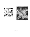
Figure 3 is a graphical representation showing microspheroidal particles comprising Quantum Dot (QD) optically detectable labels, which exhibit clear distinctive fluorescence and defined WGM profiles. -
Figure 4 is a graphical representation showing experimental spectra showing the observed shift in the WGM profile of microspheroidal particle when a monolayer of a biopolymer is adsorbed to the microspheroidal particles. QD = Quantum dot control uncoated microspheroidal particle; PSS = microspheroidal particle with adsorbed monolayer of polystyrene sulfonate (PSS); PVP = microspheroidal particle with adsorbed monolayer of polyvinyl pyrrolidone (PVP). -
Figure 5 is a graphical representation of WGM profiles for: (a) DNA was conjugated as 48-mer to Q-Sand particle; (b) Q-Sand beads hybridized to a-Transprobe DNA, the reverse complement of Transprobe; and (c) Q-Sand beads hybridized to a PCR product. - The present invention provides methods, inter alia, for detecting a molecule referred to herein as an analyte capable of entering into a binding interaction with another molecule referred to as its binding partner immobilized to the surface of a microspheroidal particle labeled with an optically detectable label which confers on the particle a defined WGM profile. Reference to "optically detectable" includes reference to detection by spectrometric means. An interaction between the analyte and the binding partner induces a change by the WGM profile. The methods described herein may be used for detecting analytes in samples and interactions between analytes. Importantly, neither the analyte nor its binding partner require a label. The interaction induces a change in the WGM profile of the microspheroidal particle. The methods of the present invention are predicated, in part, on the phenomenon that fluorescence emitters embedded within or onto a microspheroidal particle establish defined WGM profiles. The microspheroidal particles may be excited by a wide range of light sources. This facilitates measurement in many different configurations and facilitates multiplexing.
- WGMs allow only certain wavelengths of light to be emitted from a particle. The result of this phenomenon is that the usual broad emission (10-100nm wide) bands from a fluorophore becomes constrained and appears as a series of sharp peaks corresponding effectively to standing mode patterns of light within the particle.
- The WGM profile is extremely sensitive to interactions or associations with the surface of a the microspheroidal particle. Hence, even rare binding events can be detected due to the change in WGM profile.
- It is to be understood that unless otherwise indicated, the subject invention is not limited to specific microspheroidal particle formulations, manufacturing methods, diagnostic or assay protocols, or the like as such may vary. It is also to be understood that the terminology used herein is for the purpose of describing particular embodiments only and is not intended to be limiting. Reference to "an analyte" and a "binding partner" is not to be inferred that any knowledge of the structure of the analyte is known or required to be known.
- It must be noted that, as used in the subject specification, the singular forms "a", "an" and "the" include plural aspects unless the context already dictates otherwise. Thus, for example, reference to "a peak" or "a profile" includes a single peak or profile as well as two or more peaks or profile; a "microspheroidal particle" includes a single particle as well as two or more particles; and so forth.
- The present invention contemplates a method of detecting an analyte as defined in claim 1, said method comprising contacting at least one set of microspheroidal particles with a sample putatively comprising said analyte, wherein each particle within a set of microspheroidal particles comprises a quantum dot as an optically detectable label and an immobilized putative binding partner of said analyte wherein each particle set has a defined Whispering Gallery Mode (WGM) profile, wherein binding of said analyte to said immobilized binding partner results in a spectral shift in one or more peaks in said WGM profile of said at least one set of microspheroidal particles which is indicative of the presence of said analyte.
- "Microspheroidal particles" contemplated by the present invention include particles comprising any material, homogenous or otherwise which can produce one or more WGM profiles based on its optically detectable label. As will be evident to those of skill in the art, almost any material, homogenous or otherwise may be used for the microspheroidal particle. The microspheroidal particles contemplated herein may also comprise more than one substance, and as such may comprise shells, alloys or mixtures of organic and/or inorganic substances. It is advantageous for quantification of the data generated by the methods of the present invention if the microspheroidal particle comprises a substantially homogenous material with an isotropic refractive index and which is also non-absorbing (other than the optically detectable label, which is further described below).
- Particularly useful materials which may be used in accordance with the present invention and which represent specific embodiments of the present invention include materials selected from the list consisting of: silica (for example: quartz or glass), latex, titania, tin dioxide, yttria, alumina, and other binary metal oxides (such as ZnO), perovskites and other piezoelectric metal oxides (such as BaTiO3), ZnS, sucrose, agarose and other polymeric beads. In a particularly preferred embodiment, the "particle" and/or "microspheroidal particle" comprises silica.
- Thus, while many shapes of material can sustain WGM profile, it is generally practical to synthesize small spheres or spheroidal particles. Such spheres or spheroidal particles are also referred to herein as "microspheroidal particles" or "microspheres". Accordingly, in preferred embodiments of the present invention, the "particles" and "microspheroidal particles" of the present invention are substantially spherical or spheroidal or comprise a "microsphere".
- Although the particles of the present invention may be referred to as "microspheroids" the actual size of the microspheroidal particle depends on a variety of factors and the particles may or may not actually comprise measurements in the micrometer range. In one preferred embodiment the microspheroidal particles of the present invention comprise a diameter (or equivalent measurement in a non-spheroidal particle) of about 1µm to about 100µm, including 1µm, 2µm, 3µm, 4µm, 5µm, 6µm, 7µm, 8µm, 9µm, 10µm, 11µm, 12µm, 13µm, 14µm, 15µm, 16µm, 17µm, 18µm, 19µm, 20µm, 21µm, 22µm, 23µm, 24µm, 25µm, 26µm, 27µm, 28µm, 29µm, 30µm, 31µm, 32µm, 33µm, 34µm, 35µm, 36µm, 37µm, 38µm, 39µm, 40µm, 41µm, 42µm, 43µm, 44µm, 45µm, 46µm, 47µm, 48µm, 49µm, 50µm, 51µm, 52µm, 53µm, 54µm, 55µm, 56µm, 57µm, 58µm, 59µm, 60µm, 61µm, 62µm, 63µm, 64µm, 65µm, 66µm, 67µm, 68µm, 69µm, 70µm, 71µm, 72µm, 73µm, 74µm, 75µm, 76µm, 77µm, 78µm, 79µm, 80µm, 81µm, 82µm, 83µm, 84µm, 85µm, 86µm, 87µm, 88µm, 89µm, 90µm, 91µm, 92µm, 93µm, 94µm, 95µm, 96µm, 97µm, 98µm, 99µm and 100µm. Reference to these sizes of mircospheres include fractions of the whole numbers. For example, fractions between 1 and 2µm include 1.05, 1.1, 1.15, 1.2, 1.25, 1.3, 1.35, 1.4, 1.45, 1.5, 1.55, 1.6, 1.65, 1.7, 1.75, 1.8, 1.85, 1.9, 1.95 or 2.0.
- In a particular embodiment, the microspheroidal particles are microspheres.
- A set of microspheroidal particles including a set of microspheres includes a multiplicity (i.e. two or more) particles or microspheres having a common label or size or immobilized binding partner.
- As used herein, the term "optically detectable label" refers to any molecule, atom or ion which emits fluorescence or phosphorescence. The optically detectable label may be chosen to emit at any wavelength at which WGM profile may be easily resolved. This depends on the ratio of the wavelength of the emission to the particle radius. Given that the sphere radius is arbitrary, the emission may be suitably chosen from the ultraviolet (wavelength range of about 350nm to about 3nm), visible (wavelength range of about 350nm to about 800nm, near infrared (NIR) (wavelength range of about 800nm to about 1500nm) and/or infrared (IR) (wavelength range of about 1500nm to about 10µm) ranges. However, due to the ease of detection, in one particularly preferred embodiment, the optically detectable label is detectable in the visible wavelength range.
- In one particular embodiment, the optically detectable label may be an optically detectable label which emits visible radiation in response to Infrared excitation. Such optically detectable labels are also referred to herein as "upconverters".
- Accordingly, an exemplary method of detecting an analyte may comprise contacting at least one set of microspheroidal particles with a sample putatively comprising said analyte, wherein each particle within a set of microspheroidal particles comprises a label with emits visible radiation in response to infrared excitation and an immobilized putative binding partner of said analyte wherein each particle set has a defined Whispering Gallery Mode (WGM) profile, wherein binding of said analyte to said immobilized binding partner results in a change in said WGM profile of said at least one set of microspheroidal particles which is indicative of the presence of said analyte.
- The only constraint on the optically detectable label is that the emission in the chosen label should result in cavity mode emission.
- According to the invention, the optically detectable label comprises a quantum dot. In an exemplary method that does not form part of the claimed invention the scattered light from small metal particles (surface plasmon emission) may be used as an optically detectable label.
- One particularly convenient optically detectable label which may be used in accordance with the present invention is to embed fluorescent particles on or in the microspheroidal particle. These optically detectable label particles may be so small that their properties and emission become size dependent. Such small optically detectable label particles are referred to in the art as semiconductor nanoparticles, quantum dots, quantum wires, quantum rods or nanocrystals or Q-particles. However, as used herein, the term "quantum dot" or "QD" is to be understood to encompass all such particles. Furthermore, optically detectable labels comprising QDs may comprise approximately spherical or spheroidal particles, or coated spherical or spheroidal particles. However, the term QD should not be considered in any way to be limited to a spherical, spheroidal, circular, cylindrical or any other morphology of a "dot". For example, as used herein QDs may also comprise other morphologies including, inter alia, rod-like, ellipsoidal, or coated rod-like or ellipsoidal particles.
- QDs consist of a nanometer-scale crystalline core of semiconductor material; biologically active versions are typically surrounded by a protective shell and external coat. For example, QDs may comprise semiconductor crystallites which are about 2 nm to about 30 nm in diameter (e.g. 2, 3, 4, 5, 6, 7, 8, 9, 10, 11, 12, 13, 14, 15, 16, 17, 18, 19, 20, 21, 22, 23, 24, 25, 26, 27, 28, 29 or 30 nm) and may contain approximately 50-500,000 atoms within the crystal, including luminescent crystals comprising materials such as ZnS, ZnSe, ZnTe, CdS, CdSe, CdTe, PbS, PbSe, PbTe, HgS, HgSe, HgTe, Si, ZnO.
- QDs fluoresce with a broad absorption spectrum and a narrow emission spectrum. Unlike some other fluorophores, which have distinct absorption spectra, QDs absorb light over a wide spectral range, which allows quantum dots to be excited with a range of light sources, such as lasers, arc lamps, or LEDs. Furthermore, a collection of different QDs can be used in multiplex applications using only a single excitation source. However, the emission spectra for each dot is typically very narrow, in the order of about 30 nm, the exact color depending on the particle's diameter and composition. Furthermore, the narrow emission spectrum of QDs permits spectral resolution of adjacent dots. In addition to the benefits above, QDs are also relatively photostable, even during intense excitation, and are brighter than fluorophores.
- In light of the foregoing, it should also be understood that the present invention encompasses the use of different sized QDs in order to optimise the wavelengths at which WGM profiles may be generated in a microspheroidal particle.
- Furthermore, the present invention contemplates QDs which are treated with procedures such as thermal treatment, surface modification, alloying, surface passivation or capping with surface coatings to enable the QD to emit with high quantum yield and to improve the photostability for long periods of time.
- QDs are also commercially available from companies such as Quantum Dot Corp. (QDC), which produces QDs such as the Qdot [Trade Mark] 605 streptavidin conjugate, containing a cadmium-selenide core that emits at 605 nm. Qdot conjugates that emit at 525, 565, 585, and 655 nm are also available. However, it should be understood that the present invention is not limited in any way by the particular composition of the QD (or any other optically detectable label) and any QD (commercial or otherwise) may be compatible with the present invention.
- There are also many fluorescent dyes which are available in the art which may be used as fluorophores in exemplary methods that do not form part of the claimed invention. An important property of a fluorescent dye or other fluorophore, which determines it's potential for use is the excitation wavelength of the fluorophore; it must match the available wavelengths of the light source. However, many different fluorescent dyes and other fluorophores will be familiar to those of skill in the art, and the choice of fluorescent marker in no way limits the subject invention.
- Convenient "fluorophores" which may be used for the labeling of a microspheroidal particle comprise any fluorescent marker which is excitable using a light source selected from the group below:
- (i) Argon ion lasers - comprise a blue, 488 nm line, which is suitable for the excitation of many dyes and fluorochromes that fluoresce in the green to red region. Tunable argon lasers are also available that emit at a range of wavelengths (458 nm, 488 nm, 496 nm, 515 nm amongst others).
- (ii) Diode lasers - have an emission wavelength of 635 nm. Other diode lasers which are now available operate at 532 nm. This wavelength excites propidium iodide (PI) optimally. Blue diode lasers emitting light around 476 nm are also available. Such diode lasers may be conveniently employed to excite WGMs within the microspheroidal particles.
- (iii) HeNe gas lasers - operate with the red 633 nm line. Such lasers may be conveniently employed to excite WGMs within the microspheroidal particles.
- (iv) HeCd lasers - operate at 325 nm. Such lasers may be conveniently employed to excite WGMs within the microspheroidal particles.
- (v) 100 W mercury arc lamp - the most efficient light source for excitation of UV dyes like Hoechst and DAPI.
- (vi) Xe arc lamps and quartz halogen lamps may likewise be used as a means to excite WGMs and hence utilize the particles as sensors.
- In exemplary methods the fluorescent markers are selected from: Alexa Fluor dyes; BoDipy dyes, including BoDipy 630/650 and
BoDipy 650/665; Cy dyes, particularly Cy3, Cy5 and Cy 5.5; 6-FAM (Fluorescein); Fluorescein dT; Hexachlorofluorescein (HEX); 6-carboxy-4', 5'-dichloro-2', 7'- dimethoxyfluorescein (JOE); Oregon green dyes, including 488-X and 514; Rhodamine dyes, including Rhodamine Green, Rhodamine Red and ROX; Carboxytetramethylrhodamine (TAMRA); Tetrachlorofluorescein (TET); and Texas Red. - Two dyeing techniques are commonly used to fluorescently label microspheroidal particles internal dyeing and external dyeing (surface-labeling). The two techniques produce particles with unique properties, each beneficial for different applications. Internal dyeing produces extremely stable particles with typically narrow fluorescence emissions. These particles often display a greater resistance to photobleaching. As the fluorophore is inside the beads, surface groups are available for use in conjugating ligands (proteins, antibodies, nucleic acids, etc.) to the surface of the bead. For this reason, internally labeled beads are typically used in analyte-detection and immunoassay applications. Surface-labeling involves conjugation of the fluorophore to the microspheroidal particle surface. Because the fluorophores are on the surface of the particle, they are able to interact with their environment just as the fluorophores on a stained cell. The result is a particle standard that exhibits the same excitation and emission properties as stained cell samples, under a variety of different conditions, such as the presence of contaminants or changes in pH. The "environmentally responsive" nature of surface-labeled particles makes them ideally suited for mimicking biological samples. Externally labeled particles are frequently used as controls and standards in a number of applications utilizing fluorescence detection. However, the present invention contemplates the association of a particle with a fluorescent label via any means.
- The terms "phosphorescent particles", "phosphor particles" and "phosphors" are used interchangeably herein. What constitutes a phosphorescent optically detectable label would be readily understood by one of skill in the art. However, by way of example, which in no way limits the invention, suitable phosphors include small particles of ZnS, ZnS:Cu, Eu oxide and other phosphors used in display devices.
- A optically detectable label comprising a "doped particle" may include a particle which comprises occluded amounts of one or more rare earth ions, such as Eu, Y, Yb, Sm and the like.
- As used herein, the term "optically detectable label" should be understood to also encompass multiple optically detectable labels, mixtures of optically detectable labels, coated nanocrystals, alloys and other complex mixtures that would be evident to the skilled artisan. The use of all such optically detectable labels on microspheroidal particles is to be considered as being within the scope of the methods and reagents described herein.
- It has been shown that the emission of any particular label depends on the distribution of the label in the microspheroidal particle, the type of label and the concentration of label. However, the methods of the present invention are still practicable irrespective of whether the optically detectable label is at the surface of the microspheroidal particle, present as a shell within the microspheroidal particle, located at the core of the microspheroidal particle or is present in more than one of the recited locations.
- It should be noted that the methods of the present invention are not predicated on quenching of the emission from the optically detectable label. The methods of the present invention, however, are predicated, in part, on a modulation (i.e. a change) in the WGM profile of the optically detectable label as a result of a interaction or association of an analyte with a binding partner immobilized to the surface of a microspheroidal particle.
- WGMs, when dealing with electromagnetic radiation, are electromagnetic resonances that can be established when incident light interacts with a particle of higher refractive index than its surrounding medium. WGMs occur at particular resonant wavelengths of light for a given particle size, and the nature of the WGM may change with, inter alia, the size of the particle containing the WGM and the refractive indices of both the particle and the surrounding medium. Furthermore, the size of the particle can also effect the WGM established therein. WGMs are established when the incident light undergoes total internal reflection at the particle surface.
- Total internal reflection (TIR) may occur at the interface between two non-absorbing media. When a beam of light propagating in the medium of higher refractive index meets an interface at a medium of lower refractive index at an angle of incidence above a critical angle, the light is totally reflected at the interface and propagates back into the high refractive index medium. As will be evident to a person skilled in the art, in a 3-dimensional medium the light may be reflected many times within the particle of higher refractive index. In a WGM, the light is concentrated near the circumference of the particle and can be assigned a mode number and a mode order. The mode number, n, provides the number of wavelengths around the circumference of the particle, and the mode order, l, provides the number of maxima in the radial dependence of the electromagnetic field within the particle.
- Fluorescence emitters embedded on or within a particle, as defined herein, display defined WGM profiles. These modes allow only certain wavelengths of light to be emitted from the particle. The result of this phenomenon is that the usual relatively broad emission spectrum of an optically detectable label (for example, fluorophores typically emit in a 10-100nm wide band) becomes constrained and appears as a series of sharp "peaks" corresponding effectively to standing mode patterns of light within the particle. The series of peaks generated as a result of the establishment of a WGM in the microspheroidal particle of the present invention are referred to herein as "Whispering Gallery Mode Profiles" or " WGM Profiles".
- The WGM profile is extremely sensitive to both the position of the embedded optically detectable label and their concentration and spatial configuration with respect to each other. Furthermore, particle size and refractive index are also important in determining the emission wavelengths seen in a WGM profile.
- It is proposed that the position and amplitude of one or more peaks in a WGM profile may be strongly influenced by interactions or associations of the microspheroidal particle with molecules in a sample or external environment.
- In one example, association or binding of a molecule to a microspheroidal particle alters the effective refractive index of the microspheroidal particle altering the WGM profile generated by the microspheroidal particle.
- The term "refractive index" would be readily understood by a person of skill in the art. Briefly, the refractive index of a medium is a value calculated from the ratio of the speed of light in a vacuum to that in a second medium of greater density. In the case of a microspheroidal particle, a change in "effective refractive index" may be a change in the refractive index of the complete microspheroidal particle, or a change in effective refractive index may be a change in the refractive index of a region or part of the microspheroidal particle. For example a change in the effective refractive index of a microspheroidal particle may comprise a change in the refractive index of the surface and/or periphery of the microspheroidal particle.
- In one particular embodiment, the present invention contemplates a method for detecting the binding or association of a molecule to, or proximal with, the surface or sub-surface of the microspheroidal particle wherein the binding or association of the molecule to an immobilized binding partner of the molecule effects a change in the effective refractive index at the surface of the microspheroidal particle.
- A "sub-surface" includes pockets or pores surrounding the particle or which form a co-continuous interface between an internal environment of the particle and an external environment.
- As used herein, the molecule or binding partner immobilized to the microspheroidal particle or the analyte in a sample refers to any chemical entity. Such chemical entities include, but are not limited to small chemical molecule; peptides, polypeptides and proteins or analogs thereof, nucleic acid molecules or analogs thereof, metal atoms or ions or compounds comprising such atoms or ions. Of the nucleic acid molecules, short interfering RNAs (single or double stranded) [siRNAs], interfering RNA complexes (RNAi) and DNA and RNA oligonucleotides are particularly contemplated. Chemical compounds include entities produced in a combinatorial library or in a chemical library. In addition, natural product screening is contemplated from a biological source. Reference to a biological source includes an environmental sample, organism extract, plant or animal extract, serum, urine, exudate, semen, plasma, soil sample, river or sealed sample, extraterrestrial sample, amongst other sources.
- As used herein the phrase "bound to, or otherwise associated with" refers to any process by which a molecule may be associated with a microspheroidal particle. Exemplary modes by which such associations may be mediated include, but are not limited to: covalent binding, hydrogen bonding, van der Waals forces, ionic bonding, metallic bonding, polar bonding and dative (covalent) bonding and the like.
- A molecule including a binding partner may also be attached to a microspheroidal particle via an agent that promotes or increases the adsorption or binding of the molecule to the surface of the microspheroidal particle, such an agent is referred to herein as a "linker". For example, polynucleotides may be associated with a microspheroidal particle via a linker which comprises a thiol, amine or carboxyl group. Examples of suitable linkers include amino-terminated silanes such as amino-propyltrimethoxysilane or aminopropyltriethoxysilane. In addition to silanes, compounds such as poly-L-lysine that non-covalently attach to surfaces such as glass and electrostatically adsorb the phosphate groups of a polynucleotide are also within the scope of the present invention. Therefore, other molecules, including other silanes, which are suitable to promote the binding or association of a polynucleotide, polypeptide or other compound to the surface of a microspheroidal particle would be readily identified by the skilled artisan, and the present invention is not limited by the choice of linker.
- The terms "nucleic acids", "nucleotide" and "polynucleotide" include RNA, cDNA, genomic DNA, synthetic forms and mixed polymers, both sense and antisense strands, and may be chemically or biochemically modified or may contain non-natural or derivatized nucleotide bases, as will be readily appreciated by those skilled in the art. Such modifications include, for example, labels, methylation, substitution of one or more of the naturally occuring nucleotides with an analog (such as a morpholine ring), internucleotide modifications such as uncharged linkages (eg. methyl phosphonates, phosphotriesters, phosphoamidates, carbamates, etc.), charged linkages (eg. phosphorothioates, phosphorodithioates, etc.), pendent moieties (eg. polypeptides), intercalators (eg. acridine, psoralen, etc.), chelators, alkylators and modified linkages (eg. α-anomeric nucleic acids etc.). Also included are synthetic molecules that mimic polynucleotides in their ability to bind a designated sequence via hydrogen bonding and other chemical interactions. Such molecules are known in the art and include, for example, those in which peptide linkages substitute for phosphate linkages in the backbone of the molecule.
- Another embodiment of the present invention contemplates that the microspheroidal particle further comprises DNA bound to, or otherwise associated with, the surface of the microspheroidal particle.
- Still a further preferred embodiment of the present invention contemplates that the microspheroidal particle further comprises RNA or a complex of RNA (e.g. RNA - Rnase complex) bound to, or otherwise associated with, the surface of the microspheroidal particle.
- In an alternative embodiment, the present invention contemplates that the WGM profile of the microspheroidal particle detectably modulates when a peptide, polypeptide or protein or analog thereof binds to, or otherwise associated with, the surface of the microspheroidal particle.
- In one embodiment, the peptide, polypeptide or protein is an enzyme.
- In another embodiment, the peptide, polypeptide or protein is an antibody.
- The term "antibody" refers to a protein of the immunoglobulin family that is capable of combining, interacting or otherwise associating with an antigen. An antibody is, therefore, an antigen-binding molecule. The term "antigen" is used herein in its broadest sense to refer to a substance that is capable of reacting with or binding to the antigen-binding site of an antibody. With reference to the present invention, an antigen also includes the idiotype of an antibody.
- The term "immunoglobulin" is used herein to refer to a protein consisting of one or more polypeptides substantially encoded by immunoglobulin genes. The recognized immunoglobulin molecules include the κ, λ, α, γ (IgG1, IgG2, IgG3, IgG4), δ, ε and µ constant regions, light chains (κ and 1), as well as the myriad immunoglobulin variable regions. One form of immunoglobulin constitutes the basic structural unit of an antibody. This form is a tetramer and consists of two identical pairs of immunoglobulin chains, each pair having one light and one heavy chain. In each pair, the light and heavy chain variable regions are together responsible for binding to an antigen, and the constant regions are responsible for the antibody effector functions. In addition to antibodies, immunoglobulins may exist in a variety of other forms including, for example, Fv, Fab, Fab' and (Fab')2 and chimeric antibodies and all of these variants are encompassed by the term "antibody" as used herein. In addition, immunoglobulins from other animals (eg. birds, mammals, fish, amphibians, and reptiles) have similar function, but different nomenclature and these are considered "antibodies "as well.
- The microspheroidal particles may comprise anti-idiotypic antibodies bound to, or otherwise associated therewith. As used herein, the term "anti-idiotypic antibody" refers to an antibody which recognizes and binds to antigenic determinants within the variable region, for example the VH and/or VL domains, of a target antibody. These antigenic determinants within the variable region of an antibody are referred to as the "idiotype" of an antibody. Accordingly, an antibody specific for these regions is referred to as an "anti-idiotypic antibody".
- "Analogs" of peptides, polypeptides and/or proteins contemplated herein include but are not limited to peptides, polypeptides or proteins comprising modification to side chains, synthetic peptides that incorporate unnatural amino acids and/or their derivatives during synthesis and the use of crosslinkers and other methods which impose conformational constraints on the subject peptide, polypeptide or protein.
- Examples of side chain modifications include modifications of amino groups such as by reductive alkylation by reaction with an aldehyde followed by reduction with NaBH4; amidination with methylacetimidate; acylation with acetic anhydride; carbamoylation of amino groups with cyanate; trinitrobenzylation of amino groups with 2, 4, 6-trinitrobenzene sulphonic acid (TNBS); acylation of amino groups with succinic anhydride and tetrahydrophthalic anhydride; and pyridoxylation of lysine with pyridoxal-5-phosphate followed by reduction with NaBH4.
- The guanidine group of arginine residues may be modified by the formation of heterocyclic condensation products with reagents such as 2,3-butanedione, phenylglyoxal and glyoxal.
- The carboxyl group may be modified by carbodiimide activation via O-acylisourea formation followed by subsequent derivitization, for example, to a corresponding amide.
- Sulphydryl groups may be modified by methods such as carboxymethylation with iodoacetic acid or iodoacetamide; performic acid oxidation to cysteic acid; formation of a mixed disulphide with other thiol compounds; reaction with maleimide, maleic anhydride or other substituted maleimide; formation of mercurial derivatives using 4-chloromercuribenzoate, 4-chloromercuriphenylsulphonic acid, phenylmercury chloride, 2-chloromercuri-4-nitrophenol and other mercurials; carbamoylation with cyanate at alkaline pH.
- Tryptophan residues may be modified by, for example, oxidation with N-bromosuccinimide or alkylation of the indole ring with 2-hydroxy-5-nitrobenzyl bromide or sulphonyl halides. Tyrosine residues on the other hand, may be altered by nitration with tetranitromethane to form a 3-nitrotyrosine derivative.
- Modification of the imidazole ring of a histidine residue may be accomplished by alkylation with iodoacetic acid derivatives or N-carbethoxylation with diethylpyrocarbonate.
- Examples of incorporating unnatural amino acids and derivatives during peptide synthesis include, but are not limited to, use of norleucine, 4-amino butyric acid, 4-amino-3-hydroxy-5-phenylpentanoic acid, 6-aminohexanoic acid, t-butylglycine, norvaline, phenylglycine, ornithine, sarcosine, 4-amino-3-hydroxy-6-methylheptanoic acid, 2-thienyl alanine and/or D-isomers of amino acids. A list of unnatural amino acid, contemplated herein is shown in Table 2.
TABLE 2 - Codes for non-conventional amino acids Non-conventional amino acid Code Non-conventional amino acid Code α-aminobutyric acid Abu L-N-methylalanine Nmala α-amino-α-methylbutyrate Mgabu L-N-methylarginine Nmarg aminocyclopropane-carboxylate Cpro L-N-methylasparagine Nmasn L-N-methylaspartic acid Nmasp aminoisobutyric acid Aib L-N-methylcysteine Nmcys aminonorbornyl-carboxylate Norb L-N-methylglutamine Nmgln L-N-methylglutamic acid Nmglu cyclohexylalanine Chexa L-Nmethylhistidine Nmhis cyclopentylalanine Cpen L-N-methylisolleucine Nmile D-alanine Dal L-N-methylleucine Nmleu D-arginine Darg L-N-methyllysine Nmlys D-aspartic acid Dasp L-N-methylmethionine Nmmet D-cysteine Dcys L-N-methylnorleucine Nmnle D-glutamine Dgln L-N-methylnorvaline Nmnva D-glutamic acid Dglu L-N-methylornithine Nmorn D-histidine Dhis L-N-methylphenylalanine Nmphe D-isoleucine Dile L-N-methylproline Nmpro D-leucine Dleu L-N-methylserine Nmser D-lysine Dlys L-N-methylthreonine Nmthr D-methionine Dmet L-N-methyltryptophan Nmtrp D-ornithine Dorn L-N-methyltyrosine Nmtyr D-phenylalanine Dphe L-N-methylvaline Nmval D-proline Dpro L-N-methylethylglycine Nmetg D-serine Dser L-N-methyl-t-butylglycine Nmtbug D-threonine Dthr L-norleucine Nle D-tryptophan Dtrp L-norvaline Nva D-tyrosine Dtyr α-methyl-aminoisobutyrate Maib D-valine Dval α-methyl-γ-aminobutyrate Mgabu D-α-methylalanine Dmala α-methylcyclohexylalanine Mchexa D-α-methylarginine Dmarg α-methylcylcopentylalanine Mcpen D-α-methylasparagine Dmasn α-methyl-α-napthylalanine Manap D-α-methylaspartate Dmasp α-methylpenicillamine Mpen D-α-methylcysteine Dmcys N-(4-aminobutyl)glycine Nglu D-α-methylglutamine Dmgln N-(2-aminoethyl)glycine Naeg D-α-methylhistidine Dmhis N-(3-aminopropyl)glycine Norn D-α-methylisoleucine Dmile N-amino-α-methylbutyrate Nmaabu D-α-methylleucine Dmleu α-napthylalanine Anap D-α-methyllysine Dmlys N-benzylglycine Nphe D-α-methylmethionine Dmmet N-(2-carbamylethyl)glycine Ngln D-α-methylornithine Dmorn N-(carbamylmethyl)glycine Nasn D-α-methylphenylalanine Dmphe N-(2-carboxyethyl)glycine Nglu D-α-methylproline Dmpro N-(carboxymethyl)glycine Nasp D-α-methylserine Dmser N-cyclobutylglycine Ncbut D-α-methylthreonine Dmthr N-cycloheptylglycine Nchep D-α-methyltryptophan Dmtrp N-cyclohexylglycine Nchex D-α-methyltyrosine Dmty N-cyclodecylglycine Ncdec D-α-methylvaline Dmval N-cylcododecylglycine Ncdod D-N-methylalanine Dnmala N-cyclooctylglycine Ncoct D-N-methylarginine Dnmarg N-cyclopropylglycine Ncpro D-N-methylasparagine Dnmasn N-cycloundecylglycine Ncund D-N-methylaspartate Dnmasp N-(2,2-diphenylethyl)glycine Nbhm D-N-methylcysteine Dnmcys N-(3,3-diphenylpropyl)glycine Nbhe D-N-methylglutamine Dnmgln N-(3-guanidinopropyl)glycine Narg D-N-methylglutamate Dnmglu N-(1-hydroxyethyl)glycine Nthr D-N-methylhistidine Dnmhis N-(hydroxyethyl))glycine Nser D-N-methylisoleucine Dnmile N-(imidazolylethyl))glycine Nhis D-N-methylleucine Dnmleu N-(3-indolylyethyl)glycine Nhtrp D-N-methyllysine Dnmlys N-methyl-γ-aminobutyrate Nmgabu N-methylcyclohexylalanine Nmchexa D-N-methylmethionine Dnmmet D-N-methylornithine Dnmorn N-methylcyclopentylalanine Nmcpen N-methylglycine Nala D-N-methylphenylalanine Dnmphe N-methylaminoisobutyrate Nmaib D-N-methylproline Dnmpro N-(1-methylpropyl)glycine Nile D-N-methylserine Dnmser N-(2-methylpropyl)glycine Nleu D-N-methylthreonine Dnmthr D-N-methyltryptophan Dnmtrp N-(1-methylethyl)glycine Nval D-N-methyltyrosine Dnmtyr N-methyla-napthylalanine Nmanap D-N-methylvaline Dnmval N-methylpenicillamine Nmpen γ-aminobutyric acid Gabu N-(p-hydroxyphenyl)glycine Nhtyr L-t-butylglycine Tbug N-(thiomethyl)glycine Ncys L-ethylglycine Etg penicillamine Pen L-homophenylalanine Hphe L-α-methylalanine Mala L-α-methylarginine Marg L-α-methylasparagine Masn L-α-methylaspartate Masp L-α-methyl-t-butylglycine Mtbug L-α-methylcysteine Mcys L-methylethylglycine Metg L-α-methylglutamine Mgln L-α-methylglutamate Mglu L-α-methylhistidine Mhis L-α-methylhomophenylalanine Mhphe L-α-methylisoleucine Mile N-(2-methylthioethyl)glycine Nmet L-α-methylleucine Mleu L-α-methyllysine Mlys L-α-methylmethionine Mmet L-α-methylnorleucine Mnle L-α-methylnorvaline Mnva L-α-methylornithine Morn L-α-methylphenylalanine Mphe L-α-methylproline Mpro L-α-methylserine Mser L-α-methylthreonine Mthr L-α-methyltryptophan Mtrp L-α-methyltyrosine Mtyr L-α-methylvaline Mval L-N-methylhomophenylalanine Nmhphe N-(N-(2,2-diphenylethyl) carbamylmethyl)glycine Nnbhm N-(N-(3,3-diphenylpropyl) carbamylmethyl)glycine Nnbhe 1-carboxy-1-(2,2-diphenyl-ethylamino)cyclopropane Nmbc - Crosslinkers can be used, for example, to stabilize 3D conformations, using homo-bifunctional crosslinkers such as the bifunctional imido esters having (CH2)n spacer groups with n=1 to n=6, glutaraldehyde, N-hydroxysuccinimide esters and hetero-bifunctional reagents which usually contain an amino-reactive moiety such as N-hydroxysuccinimide and another group specific-reactive moiety such as maleimido or dithio moiety (SH) or carbodiimide (COOH). In addition, peptides can be conformationally constrained by, for example, incorporation of Cα and N α-methylamino acids, introduction of double bonds between Cα and Cβ atoms of amino acids and the formation of cyclic peptides or analogs by introducing covalent bonds such as forming an amide bond between the N and C termini, between two side chains or between a side chain and the N or C terminus.
- In yet another alternate preferred embodiment, the WGM profile of the microspheroidal particle detectably modulates when a carbohydrate molecule or analog thereof binds to, or otherwise associates with, the surface of the microspheroidal particle.
- In one particularly preferred embodiment, the carbohydrate molecule is a Glycosaminoglycan (GAG) molecule or GAG-like molecule.
- GAGs are ubiquitous and play pivotal roles in many of the inflammatory processes within the human body. These large molecular weight polysaccharides contribute to such processes as cancer metastasis, arthritis, transplant rejection and asthma and thus a greater understanding of these processes may lead to improved drugs for the eventual treatment of such conditions. Currently, one of the best known GAGs is the heparin family of sulfated polysaccharides and the anti-coagulant activity of these molecules is well understood.
- Heparin-Like GAGs (HLGAGs) are a heterogenous group of molecules (Conrad, Heparin binding proteins. Academic Press, San Diego, 1998; Lander and Selleck, J Cell Biol 148(2):227-232, 2000). Heparin and heparan sulfate, like all HLGAGs, are long linear polysaccharides (Sasisekharan and Venkataraman, Curr Opin Chem Biol 4(6):626-631, 2000; Casu, Ann NY Acad Sci 556:1-17, 1989; Casu, Adv Carbohydr Chem Biochem 43:51-134, 1985). They are synthesized as non-sulfated chains of repeating disaccharide units comprising glucuronic acid (GlcA) and glucosamine (GlcN) which, in the golgi, are modified at various sites along their length. Heparin is more extensively modified than heparan sulfate and most of the GlcN units are modified by a sulfate group to become N-sulfated GlcN and most GlcA units are converted to iduronic acid (IdoA) through the action of epimerase. HLGAGs are heterogenous since modifications to the sulfate chains are often incomplete. The result is extensive regions of intermediate modification.
- Thus, for example, heparan sulfate chains consist of highly sulfated, structurally flexible domains rich in 2-O-sulfated IdoA alternating with regions of low sulfation consisting predominantly of N-acetyl GlcN and GlcA, which are a rigid structure. The sulfation patterns of HLGAGs are complex especially with respect to the positioning of 6-O-sulfates. Consequently, not all HLGAG molecules are identical. It is the sulfation pattern which largely determines the protein binding characteristics of a particular HLGAG.
- Some proteins bind only to particular structural motifs within a HLGAG chain and conversely some GAGs bind only to particular sites or regions on a protein. Anti-thrombin III, for example, binds to a unique pentasaccharide sequence displaying a particular arrangement of sulfate groups and the heparin pentasaccharide binds to a specific site on the anti-thrombin III protein (Whisstock et al. J Mol Biol 301:1287-1305, 2000). Basic fibroblast-derived growth factor (FGF-2) and hepatocyte growth factor (HGF) both bind heparin, but the heparin structures that are essential for binding are quite different for each and are different from that required by anti-thrombin III (Maccarana et al. J Biol Chem 268(32):23898-23905, 1993; Lyon et al. JBiol Chem 269:11216-11223, 1994). Moreover, heparin has been shown to bind to a particular region on FGF-2 ( Faham et al. Science 271:1116-1120, 1996).
- FGF-2 recognizes a motif containing a single IdoA 2-O-sulfate in a defined position, whereas for HGF, the positioning of the GlcN 6-O-sulfate groups are critical. Some heparin molecules within a preparation will carry both the anti-thrombin III binding pentasaccharide and the FGF-2 binding motif, whereas others will carry the HGF binding motif and the FGF-2 motif and not the anti-thrombin III binding pentasaccharide. Indeed, on average only one third of the molecules within a preparation of heparin carry the anti-thrombin III binding pentasaccharide (Conrad, 1998, supra).
- GAG-like molecules may also be derived from non-mammalian sources. For example, the capsular polysaccharide from E. coli K5 is composed of an alternate α-N-acetyl glucosamine (α -GlcNAc) and β-glucuronic acid (β-GlcA) units and contains no sulfate or other charged groups. The heparin backbone consists of the following motif α-GlcNAc, β-GlcA, α-GlcNAc, β-iduronic acid (β-IdoA) with varying degrees of sulfation. The only difference between GlcA and IdoA is the configuration of the carboxylic acid group at C-5, thus the heparin backbone and the E. coli K5 backbone are extremely similar in structure.
- A detectable change in the WGM profile of the microspheroidal particle, relative an initial WGM profile, is indicative of binding or interaction between the molecule and the analyte binding partner of the molecule.
- According to the invention "a detectable change in the WGM profile" comprises a spectral shift in one or more peaks in the WGM profile.
- Thus the detectable change may comprise either a red-shift or blue-shift of one or more peaks in one WGM profile relative to another WGM profile.
- As used herein the term "red-shift" refers to the shifting of the point of maximum amplitude of one or more peaks in a WGM profile to a longer wavelength. Despite the name "red", a red-shift may occur in any part of the electromagnetic spectrum and is not limited to visible light. As used herein, the term "red-shift" includes any shifting of a peak to a longer wavelength. Conversely, the term "blue-shift" refers to any movement of a peak to a shorter wavelength.
- In a particularly preferred embodiment, the red-shift or blue-shift of a peak in a WGM profile typically comprises a change in the wavelength of the maximum amplitude of the peak of approximately 1 to 100 nm. Reference to 1 to 100nm includes wavelengths of 1, 2, 3, 4, 5, 6, 7, 8, 9, 10, 11, 12, 13, 14, 15, 16, 17, 18, 19, 20, 21, 22, 23, 24, 25, 26, 27, 28, 29, 30, 31, 32, 33, 34, 35, 36, 37, 38, 39, 40, 41, 42, 43, 44, 45, 46, 47, 48, 49, 50, 51, 52, 53, 54, 55, 56, 57, 58, 59, 60, 61, 62, 63, 64, 65, 66, 67, 68, 69, 70, 71, 72, 73, 74, 75, 76, 77, 78, 79, 80, 81, 82, 83, 84, 85, 86, 87, 88, 89, 90, 91, 92, 93, 94, 95, 96, 97, 98, 99 and 100 nm. In a particular embodiment, the red-shift or blue-shift of a peak in a WGM profile comprises a change in the wavelength of the maximum amplitude of the peak of approximately 1 to 20 nm, which includes wavelengths of 1, 2, 3, 4, 5, 6, 7, 8, 9, 10, 11, 12, 13, 14, 15, 16, 17, 18, 19 and 20 nm. Although specifically exemplified with respect to wavelength shifts in visible light peaks, the invention also contemplates equivalent and/or proportionate red-shifts and blue-shifts in other regions of the electromagnetic spectrum.
- A WGM profile of a microspheroidal particle as described herein may be ascertained using any convenient method that would be evident to one of skill in the art. Essentially any detection method which can detect one or more wavelengths of electromagnetic radiation may be used to detect a WGM profile. Preferably, the detection means is sufficiently sensitive such that it can differentiate peaks in the WGM profile, more preferably, the detection means can differentiate between two peaks which are at least 1, 2, 3, 4, 5, 6, 7, 8, 9, 10, 11, 12, 13, 14, 15, 16, 17, 18, 19, 20, 21, 22, 23, 24, 25, 26, 27, 28, 29, 30, 31, 32, 33, 34, 35, 36, 37, 38, 39, 40, 41, 42, 43, 44, 45, 46, 47, 48, 49, 50, 51, 52, 53, 54, 55, 56, 57, 58, 59, 60, 61, 62, 63, 64, 65, 66, 67, 68, 69, 70, 71, 72, 73, 74, 75, 76, 77, 78, 79, 80, 81, 82, 83, 84, 85, 86, 87, 88, 89, 90, 91, 92, 93, 94, 95, 96, 97, 98, 99 and/or 100 nm apart. Particularly convenient means which may be used to determine the WGM profile of a microspheroidal particle include a flow-cytometer, array reader and a confocal microscope.
- As used herein the term "confocal microscope" includes within its scope, laser scanning confocal microscopes (LSCM) and multiphoton confocal microscopes.
- The microspheroidal particle may be immobilized to a solid support.
- As used herein the term "solid support" refers to any solid matrix onto which a microspheroidal particle may be immobilized. In preferred embodiments of the invention, the solid support comprises a solid support which allows the WGM profile of the microspheroidal particle immobilized thereto to be detected. Accordingly, preferable solid supports are those which may be used to immobilize a microspheroidal particle for analysis using a confocal microscope. In a particularly preferred embodiment, the solid support is a microscope slide.
- The method of the present invention can be used for the following applications: environmental monitoring, such as water quality (Legionella, Giardia, Cryptosporidium, at the source) and point of care diagnostics, airborne pathogens and toxins, protein:protein interaction screening, protein:carbohydrate interaction screening and drug screening, and screening of libraries of small molecules..
- Multiplexing is enabled due to the ability to have two or more sets of microspheroidal particles. The particles in any one set may have a common optically detectable label and/or a common size and/or a common immobilized binding particle. Hence, multiple analytes may be detected using a multiplicity of sets of microspheroidal particles.
- The present invention is further described by the following non-limiting examples:
- Typically, microspheroidal particles may be prepared by overlaying commercial beads of any desired composition or size with quantum dots. For more robust materials, they should be overcoated with another silica layer to minimize interactions with the medium or adsorbates.
- Without limiting the many possibilities, described herein is a typical process used to prepare microspheroidal particles using glass/silica beads.
- 0.1g of five micron diameter commercial silica beads were placed in 20 ml 2-propanol and 20 microlitres of either mercaptopropylsilane (MPS) or aminopropylsilane (APS) was added. The solution was refluxed at 80°C to allow chemisorption of the MPS or APS, which led to the creation of mercaptan or amino groups on the bead surface. Excess MPS or APS was removed by centrifugation.
- Instead of a silane functionalized bead, the beads can also be activated by adsorbing a cationic polymer. For example without restriction and to illustrate the method, 0.1g of silica beads were mixed with 20mL of an aqueous PEI (poly(ethylene imine) solution (1g/L, 0.5M NaCl). After reacting for one hour, the solution was centrifuged to remove the excess polymer and resuspended in pure water. This procedure was repeated 3 times.
- QDs were adsorbed onto the APS or PEI coated beads by adding a suspension of QDs in chloroform to a suspension of the beads in dry 2-propanol. The amount added was such as to coat the beads with about 10 monolayers. The beads and QDs were equilibrated for 10 minutes in a rotation tumbler. Then, the coated beads were separated by centrifugation.
- The QD labeled beads can be further stabilized by coating with more silica. This was done in two ways:
- First, 5uL of APS in alkaline water or chloroform (1mL) was added to the QD coated silica microspheroidal particles and allowed to react for 1 hour with agitation using a rotation tumbler at 0.2Hz. After removing the excess APS by repeated centrifugation/resuspension cycles in alkaline water or chloroform, 5mL of "active silica" (5uL of 2 w/w % sodium silicate in 5 mL of water at pH 8.7) was added to the particles and allowed to react overnight. This resulted in about 3-5nm of silica being deposited onto the particles. Excess nucleated free silica was separated via centrifugation and the particles redispersed in 2-propanol:water (4:1). Finally the silica layer was increased using TEOS and ammonia as required to obtain the desired thickness.
- The second procedure involved direct silica growth in ethanol without a preliminary deposition step in water. This consists of adsorption of PVP and then growth of silica. Enough PVP (MW 30,000) was added to provide 60PVP molecules per nm2 of surface, by dissolving it in chloroform:2-propanol (9:1). This was immediately added to the microspheres, the mixture was sonicated and allowed to react overnight under stirring.
- The microspheres were centrifuged (5 sec at 3800rpm for 5micron silica) and re-dispersed in 2-propanol (first time). NH3 (4.2%) followed by TEOS (10vol% in 2-propanol) was added with stirring and left to deposit over 12 hours.
- A schematic showing the procedure for producing QD labeled microspheroidal particles is shown in
Figure 1 . This generic protocol allows the preparation of photostable, silica microspheres of any practical size from 1 micron up to 100 microns, labeled with one or more different nanoparticles with different emission properties. - Examples of QD labeled microspheroidal particles as viewed under a confocal microscope are shown in
Figure 2 . - Q-Sand beads were conjugated to DNA, forming a complex with a Q-Sand bead and immobilized 48-mer DNA. The fifth base position of the 48-mer was a thymidine base with an incorporated amine. This amine was used to label the DNA with a BODIPY•630/650 NHS ester using a standard condensation reaction. The WGM profile for the Q-Sand bead conjugated to the 48-mer DNA is shown in
Figure 5 , panel a. - Panel b of
Figure 5 shows the WGM profile of the Q-Sand bead of panel a conjugated to a α-Transprobe DNA which hybridizes to bases 6-24 of the DNA conjugated to the Q-Sand bead. The resulting WGM profile, as seen in panel b ofFigure 5 , was a shift of approximately 2.4nm for all peaks. In addition, the Q-factor (the measure of the quality of the microresonator) reduction was approximately 5X. - Finally, the Q-Sand beads shown in
Figure 5 , panel a, were hybridized to a PCR product containing a complementary region to DNA bases 25-48 of the DNA 48-mer. The PCR product was generated from HeLa cell DNA and prepared for hybridization by Exol and Lambda Exo digestion. The resultant WGM profile was shifted 2.4nm for all peaks. The Q-factor was approximately 10X drop from Q-Sand only control. - Surface functionalization of silica microspheroidal particles can be done in the same way used for the initial silica microspheroidal particles by refluxing the QD-silica microspheroidal particles in 2-propanol containing MPS or APS or other silane to activate the surface and add functional groups which react with the target bioadsorbate.
- 5 micron microspheroidal particles labeled with orange QDs emitting at 560 nm and overcoated with 10 nm silica were treated with MPS, centrifuged and washed. The microspheres were allowed to react in water with the conjugate, such as a nucleic acid, polypeptide, antibody, carbohydrate or the like for about 1 hour. They were then centrifuged and washed to yield Bioactive QD Microspheres (BQDM).
- Several BQDM are placed on a microscope slide under a confocal microscope. A drop of reference solution is placed on the microspheres and the spectra collected using 488nm laser excitation. Then a microlitre of a solution containing an agent which putatively interacts with the conjugate on the BQDM is added to the drop and allowed to react over half an hour. The spectrum is collected and any change in the WGM profile, such as a red-shift or blue-shift of one or more peaks, is detected, wherein an observed change is indicative of interaction between the conjugate on the microspheroidal particle and the exogenously added agent.
- Microspheroidal particles of different sizes were produced using the methods described herein. WGM profiles of each of the different particle sizes were determined using a confocal microscope.
- As shown in
Figure 3 , the WGM profile exhibited by each of the different sized particles changes with the radius of the microspheroidal particle. - QD labeled microspheroidal particles comprising different molecules bound to their surface were produced using the methods described herein. WGM profiles of each of the different microspheroidal particles were determined using a confocal microscope.
- As shown in
Figure 4 , QD refers to a QD labeled microspheroidal particle with no compound bound to the surface, PSS refers to a microspheroidal particle comprising bound polystyrene sulfonate (PSS), while PVP refers to microspheroidal particle with an adsorbed monolayer of polyvinyl pyrrolidone (PVP). - As is evident from the data, the QD labeled microspheroidal particles are sensitive to the binding of a compound to their surface. Furthermore, the WGM profile shift observed also appears sensitive to the nature of the compound binding to the surface.
- Silica microspheres with functional surface sulfhydryl groups are conjugated, via a 5' acrydite molecule, to single stranded oligonucletides, which have previously been labeled with a fluorescent dye.
- The microspheres with attached, labeled oligonucleotide, are then hybridised to complimentary or unrelated oligonucleotides or PCR products.
- The hybridised and unhybridised microspheres are extensively washed in Milli Q water and spotted out on a microscope cover slip and allowed to air dry.
- The dried microspheres are then examined on a confocal microscope with laser and wavelength filters, appropriate for the fluorescent dyes being used. The whispering gallery modes generated are recorded and compared to determine the wavelength shift in the whispering gallery mode pattern between, microspheres with additional DNA hybridised onto the microsphere surface and microspheres with labeled oligonucleotide attached only.
- The resulting shift in the wavelength pattern of the whispering gallery modes can be potentially used to determine the presence or absence of complementary DNA sequences in test samples.
- Microspheroidal particles are produced using the protocols described herein. Different beads are identifable by WGM profile. Even though there is some variability between beads of a particular type, the WGM profile for a given Target with a given fluorescent emitter on a bead of a given size will be almost equivalent. At least 50 different Q-Sand beads can be tested simultaneously.
- Microspheroidal particles are arrayed into reaction carriers. These carriers are gridded glass slides with regions for different compounds. The grids are scanned and WGMs are calculated and saved. This reading is the pre-compound control WGM.
- Each reaction carrier is tested with one or more of test molecules.
- Non-specific binding is alleviated by washing step(s).
- After washing the reaction carrier is re-scanned. Positives are identified by WGM shifts compared to pre-test molecule control WGMs.
- (3-aminopropyl)trimethoxysilane (APS 99 %), (3-mercaptopropyl)trimethoxysilane (MPS, 95 %), tetraethyl orthosilicate (TEOS, 98 %), polyvinylpyrrolidone (PVP, MW 40,000), Ammonium Hydroxide (29.1 % wt %NH3 water) (Sigma-Aldrich). 5 µm silica particles (Bangs Laboratories, Inc.) Chloroform (CH3Cl3) and 2-propanol (AnalaR, Merck, Kilsyth, Victoria).
- Olympus Fluorescence Microscope (Olympus, Bonn, Germany), Motorized Rotating Wheel, Shake and Stack (Thermohybaid, Glochester UK), Ultrasonic Cleaner (Cole-Parmer Instrument Company, Illinois, USA).
-
- * Sterilize all glass-vials and magnetic stirrers with ethanol and allow to completely Dry.
- * Use filtered tips for all pipetting.
- * All glass vials must be flat-bottomed and screw-cap between 1.5- 5ml volume.
- * Para-film all glass screw cap reaction vials when reaction requires stirring-overnight.
- * Surface functionalization of silica beads was prepared as prescribed by Brendan Toohey.
- * The ultrasonication during the wash steps and the dissolving of PVP is not essential
-
- 1. Thoroughly clean a round bottom flask x1 with acetone and x2 with 2-propanol.
- 2. Add 20ml of 2-propanol to the cleaned round bottom flask and set up in a heating mantle, use plastic lid clips to keep any lids fastened and begin to push water through the shlenk line.
- 3. The 2-propanol is required to be heated to 80°C under constant stirring for reaction to take place optimally, thus with a thermometer constantly monitor the temperature of the 2-propanol until it reaches temperature, make sure thermometer is wiped with ethanol before each temperature check.
- 4. Once temperature is reached add 20µl of APS and 0.1g of untreated Bang's Beads which equates to 1ml of the manufacturer's bead slurry and cook for 2 hours under constant stirring.
- 5. Following cooking transfer contents of flask to appropriate flasks for washing.
- 6. Wash x2 in 2-propanol then resuspend in 10ml Milli-Q water and seal vial with parafilm.
-
- Baird and Myszka, J Mol Recognit 14:261-268, 2001;
- Casu, Ann NY Acad Sci 556:1-17, 1989;
- Casu, Adv Carbohydr Chem Biochem 43:51-134, 1985;
- Conrad, Heparin binding proteins Academic Press, San Diego, 1998;
- Faham et al. Science 271:1116-1120, 1996;
- Karlsson and Stahlberg, Anal Biochem 228:274-280, 1995;
- Lander and Selleck, J Cell Biol 148(2):227-232, 2000;
- Li et al. Science 299:840-843, 2003;
- Lin et al. Science 278:840-843, 1997;
- Lyon et al. J Biol Chem 269:11216-11223, 1994;
- Maccarana et al. J Biol Chem 268(32):23898-23905, 1993;
- Malinqvist, Nature 361:186-187, 1993;
- Rich and Myszka, J Mol Recognit 15:352-376, 2002;
- Sasisekharan and Venkataraman, Curr Opin Chem Biol 4(6):626-631, 2000;
- Vollmer et al. Biophysical Journal 85:1974-1979, 2003;
- Whisstock et al. J Mol Biol 301:1287-1305, 2000;
| Step | Essential | Recommended | Avoid |
| 1. Weigh out required amount of PVP (60 PVP molecules per nm2 of S.A. of silica spheres used) in 15 ml screw |
|||
| 2. Dissolve in 2ml of the 9:1 (9ml) CHCl3: (1ml) 2-propanol solvent under gentle stirring for 1 hour or shake and vortex until media appears clear | ◆ Media with dissolved PVP appears clear | ◆ Following suspension of PVP in 1-2ml of solvent, shake & vortex | ◆ Heating during ultrasonication |
| ◆ PVP is thoroughly dissolved | ◆ Excessive ultrasonication over 15 min | ||
| ◆ Prepare PVP an hour before use by dissolving under stirring | |||
| 3. Recombine with stock 9:1 solution |
| Step | Essential | Recommended | Avoid |
| 1. Mix 200-500µl APS/MPS functionalized SiO2 slurry ((0.02g/ml) & 50-200 µl Qdots in 1.5ml Eppendorf tube | Shake manually for 1-2 minutes | APS functionalized silica beads have higher affinity for the quantum dots | Not Shaking |
| 2. Put On Motorized wheel at Min-rpm | ◆ At least 15min-1Hour | Allow to rotate for 1 hour | |
| ◆ Min-rpm | |||
| 3. Add 2-propanol to break the 2 phases shake, vortex then centrifuge @ 3600 rpm 10secs then discard the supernatant | Shake, Vortex & centrifuge @ 3600rpm for 10secs | ||
| ◆ Check that pellet fluoresces under UV light | |||
| 4. Resuspend pellet in CHCl3, shake and Ultrasonicate (Blitz) then centrifuge @ 3600 rpm 10secs. Discard the supernatant and repeat wash | ◆ Shake vigorously and ultrasonicate | Can also use 2-propanol as the wash solvent | |
| ◆ Check that pellet fluoresces under UV light when supernatant has been discarded after final wash, if it does continue onto step 5, otherwise start again | |||
| 5. Resuspend washed pellet in PVP solution prepared in PART A, then combine with stock PVP solution & Ultrasonicate briefly then allow to stir over night. | ◆ Resuspend the washed pellet with a portion (1-2ml) of PVP solution and pipette 2-3 times to maximize sample recovery then combine with stock PVP solution | Add resuspended pellet under-stirring | |
| ◆ Use a 15 ml screw cap glass-vial for reaction vessel | |||
| 6. Allow to stir overnight. If sample is successful wash x2 in 2-propanol then cover with aluminium foil and store at 4°C | ◆ Seal screw-cap vial with Para-film | Concave Bottom vials | |
| ◆ Smooth stir motion | |||
| ◆ No heating |
| Step | Essential | Recommended | Avoid |
| 1. Take 1-5ml of your PVP capped microsphere sample | ◆ Ultrasonicate (only Blitz) |
||
| 2. Combine 1:1 with stock 4.2% NH3 solution (e.g. 1ml of PVP capped bead then 1ml of 4.2% NH3 solution) | |||
| 3. Under stirring administer 100µl of TEOS [5µl pure TEOS in 1ml 2-propanol (1:200 solution)] solution to the NH3/PVP Microsphere solution and allow to stir overnight. | Add TEOS while tip is within media but add to side of vial or centre of reaction media | Concave Bottom vials | |
| Seal screw-cap vial with Para-film | |||
| Flat-Bottom screw-cap vial | |||
| Smooth stirring-motion | |||
| ◆ NO HEATING! | |||
| 4. Following successful TEOS coating wash process can be performed with 2-propanol i.e. add 1ml 2-propanol, shake well, ultrasonicate (Blitz), then centrifuge sample @ 3600rpm for 10s and discard supernatant and resuspend in fresh 2-propanol. | ◆ Cover sample with aluminum foil and store @ 4°C | ||
| ◆ Repeat wash at least 3x |
Claims (18)
- A method of detecting an analyte, said method comprising contacting a set of microspheroidal particles with a sample putatively comprising said analyte, wherein each particle within the set of microspheroidal particles comprises an immobilized binding partner of said analyte and wherein the particle set has a defined Whispering Gallery Mode (WGM) profile, wherein binding of said analyte to said immobilized binding partner results in a change in said WGM profile indicated by a spectral shift in one or more peaks in the WGM profile of said set of microspheroidal particles which is indicative of the presence of said analyte, and detecting said binding of analyte and binding partner by detecting said spectral shift in one or more peaks in said WGM profile,
characterised in that each particle within said set of microspheroidal particles comprises a quantum dot as an optically detectable label and emission from said optically detectable label establishes said WGM profile. - The method of Claim 1 wherein said microspheroidal particle comprises a material selected from the list consisting of: silica, latex, titania, tin dioxide, yttria, alumina, other binary metal oxides, perovskites and other piezoelectric metal oxides, sucrose, agarose and other polymers.
- The method of Claim 2, wherein said particle comprises silica.
- The method of any one of Claims 1 to 3 wherein said particles are spherical.
- The method of Claim 1 wherein said optically detectable label is detectable in any one or more of the ultraviolet, visible, near infrared (NIR) and/or infrared (IR) wavelength ranges.
- The method of Claim 5 wherein said optically detectable label is detectable in the visible wavelength range.
- The method of Claim 1, wherein said immobilized binding partner comprises a nucleic acid molecule.
- The method of Claim 7 wherein said nucleic acid molecule comprises DNA.
- The method of Claim 7 wherein said nucleic acid molecule comprises RNA.
- The method of Claim 1, wherein said immobilized binding partner comprises a peptide, polypeptide or protein.
- The method of Claim 10, wherein said peptide, polypeptide or protein is an enzyme.
- The method of Claim 10, wherein said peptide, polypeptide or protein is an antibody.
- The method of Claim 1, wherein said immobilized binding partner comprises a carbohydrate molecule.
- The method of Claim 13, wherein said carbohydrate is a glycosaminoglycan molecule.
- The method of Claim 1 wherein the modulation of said WGM profile comprises a red-shift of one or more peaks in said profile.
- The method of Claim 1 wherein the modulation of said WGM profile comprises a blue-shift of one or more peaks in the profile.
- The method of Claim 15 or 16 wherein the red-shift or blue-shift comprises a wavelength change of said peak or peaks of between 1 and 100 nm.
- The method of Claim 17 wherein the red-shift or blue-shift comprises a wavelength change of said peak or peaks of between 1 and 20 nm.
Applications Claiming Priority (2)
| Application Number | Priority Date | Filing Date | Title |
|---|---|---|---|
| AU2004902818A AU2004902818A0 (en) | 2004-05-26 | A method of detection | |
| PCT/AU2005/000748 WO2005116615A1 (en) | 2004-05-26 | 2005-05-26 | Biosensor using whispering gallery modes in microspheres |
Publications (3)
| Publication Number | Publication Date |
|---|---|
| EP1756548A1 EP1756548A1 (en) | 2007-02-28 |
| EP1756548A4 EP1756548A4 (en) | 2009-11-25 |
| EP1756548B1 true EP1756548B1 (en) | 2015-06-24 |
Family
ID=35450987
Family Applications (1)
| Application Number | Title | Priority Date | Filing Date |
|---|---|---|---|
| EP05742019.2A Expired - Lifetime EP1756548B1 (en) | 2004-05-26 | 2005-05-26 | Biosensor using whispering gallery modes in microspheres |
Country Status (10)
| Country | Link |
|---|---|
| US (2) | US20100227315A1 (en) |
| EP (1) | EP1756548B1 (en) |
| JP (2) | JP2008500518A (en) |
| CN (1) | CN101027546B (en) |
| BR (1) | BRPI0511325A (en) |
| CA (1) | CA2567786C (en) |
| ES (1) | ES2547928T3 (en) |
| MX (1) | MXPA06013728A (en) |
| NZ (1) | NZ551816A (en) |
| WO (1) | WO2005116615A1 (en) |
Families Citing this family (30)
| Publication number | Priority date | Publication date | Assignee | Title |
|---|---|---|---|---|
| US7903240B2 (en) | 2006-12-01 | 2011-03-08 | 3M Innovative Properties Company | Optical sensing device |
| US7933022B2 (en) | 2006-12-01 | 2011-04-26 | 3M Innovative Properties Company | Integrated optical disk resonator |
| US7903906B2 (en) | 2006-12-01 | 2011-03-08 | 3M Innovative Properties Company | Optical sensing devices and methods |
| US7702202B2 (en) | 2006-12-01 | 2010-04-20 | 3M Innovative Properties Company | Optical microresonator |
| US7486855B2 (en) | 2006-12-27 | 2009-02-03 | 3M Innovative Properties Company | Optical microresonator |
| US7512298B2 (en) | 2006-12-01 | 2009-03-31 | 3M Innovative Properties Company | Optical sensing methods |
| GB2445580A (en) * | 2007-01-11 | 2008-07-16 | Secr Defence | An encoded microsphere |
| WO2009084721A1 (en) * | 2007-12-31 | 2009-07-09 | Fujirebio Inc. | Clusters of microresonators for cavity mode optical sensing |
| JP2010091553A (en) * | 2008-09-09 | 2010-04-22 | Konica Minolta Holdings Inc | Method for detecting biomolecule |
| MX2011005366A (en) * | 2008-11-21 | 2011-11-04 | Genera Biosystems Ltd | Analyte detection assay. |
| US20130105709A1 (en) | 2010-06-04 | 2013-05-02 | Michael Himmelhaus | Optical Cavity Mode Excitations in Magnetic Fluorescent Microparticles |
| US8779389B2 (en) | 2010-06-10 | 2014-07-15 | Universite Laval | Detection method based on whispering gallery modes in microspheres floating in a solution under test |
| US8493560B2 (en) * | 2010-08-09 | 2013-07-23 | Polytechnic Institute Of New York University | Plasmonic enhancement of whispering gallery mode biosensors |
| DE102012110126B3 (en) * | 2012-10-24 | 2013-11-28 | Karlsruher Institut für Technologie | Optical element and optical sensor system |
| CN103091340A (en) * | 2013-02-22 | 2013-05-08 | 云南大学 | Micro-strip surface whispering gallery mode sensor |
| DE102014104595A1 (en) * | 2014-04-01 | 2015-10-01 | Michael Himmelhaus | Method and device for label-free detection of an analyte |
| CN106814185B (en) * | 2017-01-11 | 2018-05-08 | 东南大学 | A kind of micro-fluidic detection chip based on Whispering-gallery-mode microcavity array |
| CN109142703B (en) * | 2017-06-28 | 2021-07-13 | 南京理工大学 | Detection method of aflatoxin M1 based on water-soluble perovskite nanocrystals |
| KR101960616B1 (en) * | 2017-09-28 | 2019-03-21 | (주)바이오스퀘어 | Highly sensitive biomolecule detection method based on multiple quantum dots |
| EP3938204A4 (en) * | 2019-03-14 | 2023-02-22 | The Regents of The University of California | STIMULUS-RESPONSIVE COMPOSITIONS, IMAGING SYSTEMS AND METHODS OF USE FOR BIOMEDICAL APPLICATIONS |
| WO2020190063A1 (en) * | 2019-03-20 | 2020-09-24 | (주)바이오스퀘어 | Standard material composition for verifying bioanalyzer and standard strip using same |
| IL293578A (en) | 2019-12-09 | 2022-08-01 | Deepsight Tech Inc | Whispering gallery mode resonators for sensing applications |
| CN115485549B (en) * | 2020-03-30 | 2025-11-11 | 深视超声科技公司 | Optical microresonator array device for ultrasonic sensing |
| CN111999270A (en) * | 2020-06-10 | 2020-11-27 | 北京工业大学 | Exosome detection method based on whispering gallery mode optical microcavity |
| CN116113825A (en) | 2020-07-01 | 2023-05-12 | 深视超声科技公司 | Acousto-optic harmonic imaging with optical sensor |
| EP4271521A4 (en) * | 2020-12-31 | 2024-11-20 | The Board Of Trustees Of The University Of Illinois | SPECIFIC DETECTION OF NUCLEIC ACID SEQUENCES USING ACTIVATION CLEAVAGE AND COUNTING (ACC) TECHNOLOGY |
| US20230280243A1 (en) * | 2021-10-01 | 2023-09-07 | Pnp Research Llc | Optical background suppression in binding assays that employ polymeric microspheres |
| DE102022001000B3 (en) | 2022-03-16 | 2023-06-07 | FlulDect GmbH | Method and device for label-free detection of an analyte |
| CN115060653B (en) * | 2022-07-04 | 2025-03-21 | 东北大学 | Protein molecule concentration detector based on whispering gallery mode optical microcavity singular point |
| CN121762450A (en) * | 2026-03-03 | 2026-03-31 | 德路通(石家庄)生物科技有限公司 | Echo wall mode sensor and preparation method and application thereof |
Citations (3)
| Publication number | Priority date | Publication date | Assignee | Title |
|---|---|---|---|---|
| WO2002013337A1 (en) | 2000-08-08 | 2002-02-14 | California Institute Of Technology | Optical sensing based on whispering-gallery-mode microcavity |
| US20020172457A1 (en) | 2000-06-28 | 2002-11-21 | Tapalian Haig Charles | Coated optical microcavity resonator chemical sensor |
| US6583399B1 (en) | 1999-11-22 | 2003-06-24 | California Institute Of Technology | Optical resonator microsphere sensor with altering Q-factor |
Family Cites Families (15)
| Publication number | Priority date | Publication date | Assignee | Title |
|---|---|---|---|---|
| US5200314A (en) * | 1990-03-23 | 1993-04-06 | Chiron Corporation | Polynucleotide capture assay employing in vitro amplification |
| US5117466A (en) * | 1991-04-30 | 1992-05-26 | The United States Of America As Represented By The United States Department Of Energy | Integrated fluorescence analysis system |
| US5384265A (en) * | 1993-03-26 | 1995-01-24 | Geo-Centers, Inc. | Biomolecules bound to catalytic inorganic particles, immunoassays using the same |
| US6544732B1 (en) * | 1999-05-20 | 2003-04-08 | Illumina, Inc. | Encoding and decoding of array sensors utilizing nanocrystals |
| CA2384977A1 (en) * | 1999-10-14 | 2001-06-07 | University Of Utah Research Foundation | Resonant optical cavities for high-sensitivity, high-throughput biological sensors and methods |
| JP2004500569A (en) * | 2000-02-25 | 2004-01-08 | ルミネックス コーポレイション | Internal standards and controls for multiplex assays |
| US6777244B2 (en) * | 2000-12-06 | 2004-08-17 | Hrl Laboratories, Llc | Compact sensor using microcavity structures |
| US6551788B1 (en) * | 2001-11-28 | 2003-04-22 | Beckman Coulter, Inc. | Particle-based ligand assay with extended dynamic range |
| JP2004083653A (en) * | 2002-08-23 | 2004-03-18 | Sharp Corp | Light emitting device, phosphor and method of manufacturing the same |
| AU2003284319A1 (en) * | 2002-10-22 | 2004-05-13 | Polytechnic University | Enhancing the sensitivity of a microsphere sensor |
| US7122384B2 (en) | 2002-11-06 | 2006-10-17 | E. I. Du Pont De Nemours And Company | Resonant light scattering microparticle methods |
| US7259855B2 (en) * | 2003-10-14 | 2007-08-21 | 3M Innovative Properties Company | Porous microsphere resonators |
| US7781226B2 (en) * | 2004-02-27 | 2010-08-24 | The Board Of Regents Of The University Of Texas System | Particle on membrane assay system |
| US7901883B2 (en) * | 2004-12-10 | 2011-03-08 | Genera Biosystems Limited | Human papilloma virus (HPV) detection using nucleic acid probes, microbeads and fluorescent-activated cell sorter (FACS) |
| RU2480732C2 (en) * | 2007-04-05 | 2013-04-27 | Дженера Байосистемз Лимитед | Compositions and detection methods |
-
2005
- 2005-05-26 US US11/597,484 patent/US20100227315A1/en not_active Abandoned
- 2005-05-26 BR BRPI0511325-3A patent/BRPI0511325A/en not_active IP Right Cessation
- 2005-05-26 MX MXPA06013728A patent/MXPA06013728A/en active IP Right Grant
- 2005-05-26 CN CN200580020502XA patent/CN101027546B/en not_active Expired - Fee Related
- 2005-05-26 NZ NZ551816A patent/NZ551816A/en not_active IP Right Cessation
- 2005-05-26 JP JP2007513605A patent/JP2008500518A/en active Pending
- 2005-05-26 EP EP05742019.2A patent/EP1756548B1/en not_active Expired - Lifetime
- 2005-05-26 CA CA2567786A patent/CA2567786C/en not_active Expired - Fee Related
- 2005-05-26 ES ES05742019.2T patent/ES2547928T3/en not_active Expired - Lifetime
- 2005-05-26 WO PCT/AU2005/000748 patent/WO2005116615A1/en not_active Ceased
-
2012
- 2012-02-07 JP JP2012023728A patent/JP2012137490A/en active Pending
-
2013
- 2013-02-22 US US13/774,298 patent/US9354174B2/en not_active Expired - Fee Related
Patent Citations (3)
| Publication number | Priority date | Publication date | Assignee | Title |
|---|---|---|---|---|
| US6583399B1 (en) | 1999-11-22 | 2003-06-24 | California Institute Of Technology | Optical resonator microsphere sensor with altering Q-factor |
| US20020172457A1 (en) | 2000-06-28 | 2002-11-21 | Tapalian Haig Charles | Coated optical microcavity resonator chemical sensor |
| WO2002013337A1 (en) | 2000-08-08 | 2002-02-14 | California Institute Of Technology | Optical sensing based on whispering-gallery-mode microcavity |
Non-Patent Citations (17)
| Title |
|---|
| ARTEMYEV, MV ET AL.: "Light Trapped in a Photonic Dot: Microspheres Act as a Cavity for Quantum Dot Emission", NANO LETTERS, vol. 1, no. Issue 6, 2001, pages 309 - 314 |
| ARTEMYEV, MV ET AL.: "Photons confined in hollow microspheres", APPLIED PHYSICS LETTERS, vol. 78, no. Issue 8, 2001, pages 1032 - 1034, XP012028642 |
| ARTEMYEV, MV ET AL.: "Quantum dots in photonic dots", APPLIED PHYSICS LETTERS, vol. 76, no. Issue 1 1, 2000, pages 1353 - 1355, XP012024800 |
| BENNER, RE ET AL.: "Observation of Structure Resonances in the Fluorescence Spectra from Microspheres", PHYSICAL REVIEW LETTERS, vol. 44, no. Issue 7, 1980, pages 475 - 478, XP055078402 |
| FAN, XD ET AL.: "Enhanced spontaneous emission from semiconductor nanocrystals embedded in whispering gallery optical microcavities", PHYSICAL REVIEW B, vol. 64, no. Issue 11, 2001, pages 115310, XP055269361 |
| GOMEZ, DE ET AL.: "Tunable Whispering Gallery Mode Emission from Quantum-Dot-Doped Microspheres", SMALL, vol. 1, no. Issue 2, 2005, pages 238 - 241, XP002549921 |
| HILL S C ET AL: "Structural resonances observed in the fluorescence emission from small spheres on substrates", APPLIED OPTICS, OPTICAL SOCIETY OF AMERICA, WASHINGTON, DC; US, vol. 23, no. 11, 1 June 1984 (1984-06-01), pages 1680 - 1683, XP003028139, ISSN: 0003-6935 * |
| HILL, SC ET AL.: "Structural resonances observed in the fluorescence emission from small spheres on substrates", APPLIED OPTICS, vol. 23, no. Issue 11, 1984, pages 1680 - 1683, XP003028139 |
| JIA, R ET AL.: "Photoluminescence Study of CdSexS1-x Quantum Dots in a Glass Spherical Microcavity", CHINESE PHYSICS LETTERS, vol. 18, no. Issue 10, 2001, pages 1350 - 1352, XP055269354 |
| JIA, R ET AL.: "Quantum dots in glass spherical microcavity", APPLIED PHYSICS LETTERS, vol. 79, no. Issue 2, 2001, pages 153 - 155, XP012029354 |
| MÖLLER ET AL.: "Mode identification in spherical microcavities doped with quantum dots", APPLIED PHYSICS LETTERS, vol. 80, no. Issue 18, 2002, pages 3253 - 3255 |
| MÖLLER, B ET AL.: "Mode control by nanoengineering light emitters in spherical microcavities", APPLIED PHYSICS LETTERS, vol. 83, no. Issue 13, 2003, pages 2686 - 2688, XP012035258 |
| ORAEVSKII, AN ET AL.: "Quantum dot laser", QUANTUM ELECTRONICS, vol. 28, no. Issue 3, 1998, pages 203 - 208, XP055270098 |
| PELTON, M ET AL.: "Ultralow threshold laser using a single quantum dot and a microsphere cavity", PHYSICAL REVIEW A, vol. 59, no. 3, 1999, pages 2418 - 2421, XP002304598 |
| R. BENNER ET AL: "Observation of Structure Resonances in the Fluorescence Spectra from Microspheres", PHYSICAL REVIEW LETTERS, vol. 44, no. 7, 1 February 1980 (1980-02-01), pages 475 - 478, XP055078402, ISSN: 0031-9007, DOI: 10.1103/PhysRevLett.44.475 * |
| VAHALA, KJ: "Optical Microcavities", NATURE, vol. 424, 2003, pages 839 - 846, XP055270877 |
| VOLLMER, F ET AL.: "Protein detection by optical shift of a resonant microcavity", APPLIED PHYSICS LETTERS, vol. 80, no. Issue 21, 2002, pages 4057 - 4059, XP012031054 |
Also Published As
| Publication number | Publication date |
|---|---|
| MXPA06013728A (en) | 2007-05-09 |
| NZ551816A (en) | 2010-10-29 |
| BRPI0511325A (en) | 2007-12-04 |
| US20100227315A1 (en) | 2010-09-09 |
| JP2012137490A (en) | 2012-07-19 |
| EP1756548A1 (en) | 2007-02-28 |
| US9354174B2 (en) | 2016-05-31 |
| CN101027546A (en) | 2007-08-29 |
| CA2567786A1 (en) | 2005-12-08 |
| HK1101983A1 (en) | 2007-11-02 |
| JP2008500518A (en) | 2008-01-10 |
| EP1756548A4 (en) | 2009-11-25 |
| US20130189706A1 (en) | 2013-07-25 |
| WO2005116615A1 (en) | 2005-12-08 |
| ES2547928T3 (en) | 2015-10-09 |
| CN101027546B (en) | 2013-09-25 |
| CA2567786C (en) | 2015-01-27 |
Similar Documents
| Publication | Publication Date | Title |
|---|---|---|
| US9354174B2 (en) | Biosensor using whispering gallery modes in microspheres | |
| EP2368115B1 (en) | Analyte detection assay | |
| JP4740111B2 (en) | Methods and compositions for detecting and analyzing polynucleotide binding protein interactions using light collecting multichromophores | |
| JPH07121238B2 (en) | Method for homogeneous assay of specific polynucleotides | |
| EP1384504A2 (en) | Methods for producing ligand arrays | |
| AU2007333001A2 (en) | Nanoplasmonic molecular ruler for nuclease activity and DNA footprinting | |
| WO2011100669A2 (en) | Lable-free multiplexing bioassays using fluorescent conjugated polymers and barcoded nanoparticles | |
| US20030109062A1 (en) | Reactive solid support and DNA fragment detection tool | |
| EP1644379B1 (en) | Rotaxane compound, rotaxane-bonded solid substrate, and biochip using the same | |
| EP1692514A1 (en) | Binding assay components | |
| AU2005248419C1 (en) | Biosensor using whispering gallery modes in microspheres | |
| HK1101983B (en) | Biosensor using whispering gallery modes in microspheres | |
| WO2009112498A1 (en) | Surface attachment | |
| US20040241880A1 (en) | Ligand array assays having reduced fluorescent dye degradation and compositions for practicing the same | |
| US20040241663A1 (en) | Ligand array processing methods that include a high surface tension fluid deposition step and compositions for practicing the same | |
| KR20040039349A (en) | Support for ligand immobilization | |
| US20100227771A1 (en) | Methods for detection of target on responsive polymeric biochips | |
| BRPI0511325B1 (en) | PRODUCT OF ANALYSIS AND RESPECTIVE METHOD OF DETECTION | |
| Wang et al. | Conjugated polyelectrolyte amplified fluorescent assays with probe functionalized silica nanoparticles for chemical and biological sensing | |
| PH12017000123A1 (en) | Target optimization in nucleic acid based lateral flow strip biosensor (lfsb) detection | |
| JPS62244398A (en) | Detection of dna and/or rna | |
| JP2003189856A (en) | Method for labeling nucleic acid |
Legal Events
| Date | Code | Title | Description |
|---|---|---|---|
| PUAI | Public reference made under article 153(3) epc to a published international application that has entered the european phase |
Free format text: ORIGINAL CODE: 0009012 |
|
| 17P | Request for examination filed |
Effective date: 20061221 |
|
| AK | Designated contracting states |
Kind code of ref document: A1 Designated state(s): AT BE BG CH CY CZ DE DK EE ES FI FR GB GR HU IE IS IT LI LT LU MC NL PL PT RO SE SI SK TR |
|
| DAX | Request for extension of the european patent (deleted) | ||
| REG | Reference to a national code |
Ref country code: HK Ref legal event code: DE Ref document number: 1101983 Country of ref document: HK |
|
| RAP1 | Party data changed (applicant data changed or rights of an application transferred) |
Owner name: MULVANEY, PAUL Owner name: GENERA BIOSYSTEMS LIMITED |
|
| RIC1 | Information provided on ipc code assigned before grant |
Ipc: G01N 21/77 20060101ALI20091013BHEP Ipc: G01N 21/55 20060101ALI20091013BHEP Ipc: G01N 21/63 20060101ALI20091013BHEP Ipc: G01N 21/25 20060101AFI20051213BHEP |
|
| A4 | Supplementary search report drawn up and despatched |
Effective date: 20091026 |
|
| 17Q | First examination report despatched |
Effective date: 20100112 |
|
| TPAC | Observations filed by third parties |
Free format text: ORIGINAL CODE: EPIDOSNTIPA |
|
| TPAC | Observations filed by third parties |
Free format text: ORIGINAL CODE: EPIDOSNTIPA |
|
| REG | Reference to a national code |
Ref country code: DE Ref legal event code: R079 Ref document number: 602005046813 Country of ref document: DE Free format text: PREVIOUS MAIN CLASS: G01N0021250000 Ipc: G01N0021770000 |
|
| GRAP | Despatch of communication of intention to grant a patent |
Free format text: ORIGINAL CODE: EPIDOSNIGR1 |
|
| RIC1 | Information provided on ipc code assigned before grant |
Ipc: B82Y 10/00 20110101ALI20141201BHEP Ipc: B82Y 20/00 20110101ALI20141201BHEP Ipc: G01N 21/77 20060101AFI20141201BHEP Ipc: G01N 33/543 20060101ALI20141201BHEP |
|
| INTG | Intention to grant announced |
Effective date: 20141223 |
|
| TPAA | Information related to observations by third parties modified |
Free format text: ORIGINAL CODE: EPIDOSCTIPA |
|
| GRAS | Grant fee paid |
Free format text: ORIGINAL CODE: EPIDOSNIGR3 |
|
| GRAA | (expected) grant |
Free format text: ORIGINAL CODE: 0009210 |
|
| AK | Designated contracting states |
Kind code of ref document: B1 Designated state(s): AT BE BG CH CY CZ DE DK EE ES FI FR GB GR HU IE IS IT LI LT LU MC NL PL PT RO SE SI SK TR |
|
| REG | Reference to a national code |
Ref country code: GB Ref legal event code: FG4D |
|
| REG | Reference to a national code |
Ref country code: CH Ref legal event code: EP |
|
| REG | Reference to a national code |
Ref country code: AT Ref legal event code: REF Ref document number: 733122 Country of ref document: AT Kind code of ref document: T Effective date: 20150715 |
|
| REG | Reference to a national code |
Ref country code: IE Ref legal event code: FG4D |
|
| REG | Reference to a national code |
Ref country code: DE Ref legal event code: R096 Ref document number: 602005046813 Country of ref document: DE |
|
| REG | Reference to a national code |
Ref country code: ES Ref legal event code: FG2A Ref document number: 2547928 Country of ref document: ES Kind code of ref document: T3 Effective date: 20151009 |
|
| PG25 | Lapsed in a contracting state [announced via postgrant information from national office to epo] |
Ref country code: LT Free format text: LAPSE BECAUSE OF FAILURE TO SUBMIT A TRANSLATION OF THE DESCRIPTION OR TO PAY THE FEE WITHIN THE PRESCRIBED TIME-LIMIT Effective date: 20150624 Ref country code: FI Free format text: LAPSE BECAUSE OF FAILURE TO SUBMIT A TRANSLATION OF THE DESCRIPTION OR TO PAY THE FEE WITHIN THE PRESCRIBED TIME-LIMIT Effective date: 20150624 |
|
| REG | Reference to a national code |
Ref country code: AT Ref legal event code: MK05 Ref document number: 733122 Country of ref document: AT Kind code of ref document: T Effective date: 20150624 |
|
| REG | Reference to a national code |
Ref country code: LT Ref legal event code: MG4D |
|
| PG25 | Lapsed in a contracting state [announced via postgrant information from national office to epo] |
Ref country code: GR Free format text: LAPSE BECAUSE OF FAILURE TO SUBMIT A TRANSLATION OF THE DESCRIPTION OR TO PAY THE FEE WITHIN THE PRESCRIBED TIME-LIMIT Effective date: 20150925 Ref country code: BG Free format text: LAPSE BECAUSE OF FAILURE TO SUBMIT A TRANSLATION OF THE DESCRIPTION OR TO PAY THE FEE WITHIN THE PRESCRIBED TIME-LIMIT Effective date: 20150924 |
|
| REG | Reference to a national code |
Ref country code: NL Ref legal event code: MP Effective date: 20150624 |
|
| PG25 | Lapsed in a contracting state [announced via postgrant information from national office to epo] |
Ref country code: EE Free format text: LAPSE BECAUSE OF FAILURE TO SUBMIT A TRANSLATION OF THE DESCRIPTION OR TO PAY THE FEE WITHIN THE PRESCRIBED TIME-LIMIT Effective date: 20150624 |
|
| PG25 | Lapsed in a contracting state [announced via postgrant information from national office to epo] |
Ref country code: SK Free format text: LAPSE BECAUSE OF FAILURE TO SUBMIT A TRANSLATION OF THE DESCRIPTION OR TO PAY THE FEE WITHIN THE PRESCRIBED TIME-LIMIT Effective date: 20150624 Ref country code: PT Free format text: LAPSE BECAUSE OF FAILURE TO SUBMIT A TRANSLATION OF THE DESCRIPTION OR TO PAY THE FEE WITHIN THE PRESCRIBED TIME-LIMIT Effective date: 20151026 Ref country code: AT Free format text: LAPSE BECAUSE OF FAILURE TO SUBMIT A TRANSLATION OF THE DESCRIPTION OR TO PAY THE FEE WITHIN THE PRESCRIBED TIME-LIMIT Effective date: 20150624 Ref country code: IS Free format text: LAPSE BECAUSE OF FAILURE TO SUBMIT A TRANSLATION OF THE DESCRIPTION OR TO PAY THE FEE WITHIN THE PRESCRIBED TIME-LIMIT Effective date: 20151024 Ref country code: RO Free format text: LAPSE BECAUSE OF NON-PAYMENT OF DUE FEES Effective date: 20150624 Ref country code: CZ Free format text: LAPSE BECAUSE OF FAILURE TO SUBMIT A TRANSLATION OF THE DESCRIPTION OR TO PAY THE FEE WITHIN THE PRESCRIBED TIME-LIMIT Effective date: 20150624 Ref country code: PL Free format text: LAPSE BECAUSE OF FAILURE TO SUBMIT A TRANSLATION OF THE DESCRIPTION OR TO PAY THE FEE WITHIN THE PRESCRIBED TIME-LIMIT Effective date: 20150624 |
|
| REG | Reference to a national code |
Ref country code: DE Ref legal event code: R026 Ref document number: 602005046813 Country of ref document: DE |
|
| PLBI | Opposition filed |
Free format text: ORIGINAL CODE: 0009260 |
|
| PLAB | Opposition data, opponent's data or that of the opponent's representative modified |
Free format text: ORIGINAL CODE: 0009299OPPO |
|
| PLAB | Opposition data, opponent's data or that of the opponent's representative modified |
Free format text: ORIGINAL CODE: 0009299OPPO |
|
| PG25 | Lapsed in a contracting state [announced via postgrant information from national office to epo] |
Ref country code: DK Free format text: LAPSE BECAUSE OF FAILURE TO SUBMIT A TRANSLATION OF THE DESCRIPTION OR TO PAY THE FEE WITHIN THE PRESCRIBED TIME-LIMIT Effective date: 20150624 |
|
| PLAX | Notice of opposition and request to file observation + time limit sent |
Free format text: ORIGINAL CODE: EPIDOSNOBS2 |
|
| 26 | Opposition filed |
Opponent name: DR. MICHEAL HIMMELHAUS - NANOBIOANALYTICS Effective date: 20160324 |
|
| R26 | Opposition filed (corrected) |
Opponent name: DR. MICHAEL HIMMELHAUS - NANOBIOANALYTICS Effective date: 20160324 |
|
| REG | Reference to a national code |
Ref country code: HK Ref legal event code: GR Ref document number: 1101983 Country of ref document: HK |
|
| R26 | Opposition filed (corrected) |
Opponent name: DR. MICHAEL HIMMELHAUS - NANOBIOANALYTICS Effective date: 20160324 |
|
| REG | Reference to a national code |
Ref country code: FR Ref legal event code: PLFP Year of fee payment: 12 |
|
| PLAF | Information modified related to communication of a notice of opposition and request to file observations + time limit |
Free format text: ORIGINAL CODE: EPIDOSCOBS2 |
|
| PG25 | Lapsed in a contracting state [announced via postgrant information from national office to epo] |
Ref country code: SI Free format text: LAPSE BECAUSE OF FAILURE TO SUBMIT A TRANSLATION OF THE DESCRIPTION OR TO PAY THE FEE WITHIN THE PRESCRIBED TIME-LIMIT Effective date: 20150624 Ref country code: BE Free format text: LAPSE BECAUSE OF NON-PAYMENT OF DUE FEES Effective date: 20160531 |
|
| PLBB | Reply of patent proprietor to notice(s) of opposition received |
Free format text: ORIGINAL CODE: EPIDOSNOBS3 |
|
| PG25 | Lapsed in a contracting state [announced via postgrant information from national office to epo] |
Ref country code: LU Free format text: LAPSE BECAUSE OF FAILURE TO SUBMIT A TRANSLATION OF THE DESCRIPTION OR TO PAY THE FEE WITHIN THE PRESCRIBED TIME-LIMIT Effective date: 20160526 Ref country code: BE Free format text: LAPSE BECAUSE OF FAILURE TO SUBMIT A TRANSLATION OF THE DESCRIPTION OR TO PAY THE FEE WITHIN THE PRESCRIBED TIME-LIMIT Effective date: 20150624 |
|
| REG | Reference to a national code |
Ref country code: CH Ref legal event code: PL |
|
| PG25 | Lapsed in a contracting state [announced via postgrant information from national office to epo] |
Ref country code: CH Free format text: LAPSE BECAUSE OF NON-PAYMENT OF DUE FEES Effective date: 20160531 Ref country code: LI Free format text: LAPSE BECAUSE OF NON-PAYMENT OF DUE FEES Effective date: 20160531 |
|
| REG | Reference to a national code |
Ref country code: FR Ref legal event code: PLFP Year of fee payment: 13 |
|
| PG25 | Lapsed in a contracting state [announced via postgrant information from national office to epo] |
Ref country code: NL Free format text: LAPSE BECAUSE OF FAILURE TO SUBMIT A TRANSLATION OF THE DESCRIPTION OR TO PAY THE FEE WITHIN THE PRESCRIBED TIME-LIMIT Effective date: 20150624 Ref country code: SE Free format text: LAPSE BECAUSE OF FAILURE TO SUBMIT A TRANSLATION OF THE DESCRIPTION OR TO PAY THE FEE WITHIN THE PRESCRIBED TIME-LIMIT Effective date: 20150624 |
|
| REG | Reference to a national code |
Ref country code: DE Ref legal event code: R100 Ref document number: 602005046813 Country of ref document: DE |
|
| PLCK | Communication despatched that opposition was rejected |
Free format text: ORIGINAL CODE: EPIDOSNREJ1 |
|
| PLBN | Opposition rejected |
Free format text: ORIGINAL CODE: 0009273 |
|
| STAA | Information on the status of an ep patent application or granted ep patent |
Free format text: STATUS: OPPOSITION REJECTED |
|
| 27O | Opposition rejected |
Effective date: 20171013 |
|
| REG | Reference to a national code |
Ref country code: FR Ref legal event code: PLFP Year of fee payment: 14 |
|
| PG25 | Lapsed in a contracting state [announced via postgrant information from national office to epo] |
Ref country code: CY Free format text: LAPSE BECAUSE OF FAILURE TO SUBMIT A TRANSLATION OF THE DESCRIPTION OR TO PAY THE FEE WITHIN THE PRESCRIBED TIME-LIMIT Effective date: 20150624 Ref country code: HU Free format text: LAPSE BECAUSE OF FAILURE TO SUBMIT A TRANSLATION OF THE DESCRIPTION OR TO PAY THE FEE WITHIN THE PRESCRIBED TIME-LIMIT; INVALID AB INITIO Effective date: 20050526 |
|
| PG25 | Lapsed in a contracting state [announced via postgrant information from national office to epo] |
Ref country code: TR Free format text: LAPSE BECAUSE OF FAILURE TO SUBMIT A TRANSLATION OF THE DESCRIPTION OR TO PAY THE FEE WITHIN THE PRESCRIBED TIME-LIMIT Effective date: 20150624 Ref country code: MC Free format text: LAPSE BECAUSE OF FAILURE TO SUBMIT A TRANSLATION OF THE DESCRIPTION OR TO PAY THE FEE WITHIN THE PRESCRIBED TIME-LIMIT Effective date: 20150624 |
|
| PGFP | Annual fee paid to national office [announced via postgrant information from national office to epo] |
Ref country code: IE Payment date: 20190522 Year of fee payment: 15 Ref country code: IT Payment date: 20190527 Year of fee payment: 15 Ref country code: DE Payment date: 20190521 Year of fee payment: 15 Ref country code: ES Payment date: 20190620 Year of fee payment: 15 |
|
| PGFP | Annual fee paid to national office [announced via postgrant information from national office to epo] |
Ref country code: FR Payment date: 20190523 Year of fee payment: 15 |
|
| PGFP | Annual fee paid to national office [announced via postgrant information from national office to epo] |
Ref country code: GB Payment date: 20190521 Year of fee payment: 15 |
|
| REG | Reference to a national code |
Ref country code: DE Ref legal event code: R119 Ref document number: 602005046813 Country of ref document: DE |
|
| GBPC | Gb: european patent ceased through non-payment of renewal fee |
Effective date: 20200526 |
|
| PG25 | Lapsed in a contracting state [announced via postgrant information from national office to epo] |
Ref country code: GB Free format text: LAPSE BECAUSE OF NON-PAYMENT OF DUE FEES Effective date: 20200526 Ref country code: FR Free format text: LAPSE BECAUSE OF NON-PAYMENT OF DUE FEES Effective date: 20200531 Ref country code: IE Free format text: LAPSE BECAUSE OF NON-PAYMENT OF DUE FEES Effective date: 20200526 |
|
| PG25 | Lapsed in a contracting state [announced via postgrant information from national office to epo] |
Ref country code: DE Free format text: LAPSE BECAUSE OF NON-PAYMENT OF DUE FEES Effective date: 20201201 |
|
| REG | Reference to a national code |
Ref country code: ES Ref legal event code: FD2A Effective date: 20211006 |
|
| PG25 | Lapsed in a contracting state [announced via postgrant information from national office to epo] |
Ref country code: IT Free format text: LAPSE BECAUSE OF NON-PAYMENT OF DUE FEES Effective date: 20200526 |
|
| PG25 | Lapsed in a contracting state [announced via postgrant information from national office to epo] |
Ref country code: ES Free format text: LAPSE BECAUSE OF NON-PAYMENT OF DUE FEES Effective date: 20200527 |