EP1755357A2 - Coaxial two-way drive unit for horn speakers - Google Patents
Coaxial two-way drive unit for horn speakers Download PDFInfo
- Publication number
- EP1755357A2 EP1755357A2 EP06117048A EP06117048A EP1755357A2 EP 1755357 A2 EP1755357 A2 EP 1755357A2 EP 06117048 A EP06117048 A EP 06117048A EP 06117048 A EP06117048 A EP 06117048A EP 1755357 A2 EP1755357 A2 EP 1755357A2
- Authority
- EP
- European Patent Office
- Prior art keywords
- drive unit
- cone
- voice coil
- facing towards
- mouth
- Prior art date
- Legal status (The legal status is an assumption and is not a legal conclusion. Google has not performed a legal analysis and makes no representation as to the accuracy of the status listed.)
- Granted
Links
Images



Classifications
-
- H—ELECTRICITY
- H04—ELECTRIC COMMUNICATION TECHNIQUE
- H04R—LOUDSPEAKERS, MICROPHONES, GRAMOPHONE PICK-UPS OR LIKE ACOUSTIC ELECTROMECHANICAL TRANSDUCERS; ELECTRIC HEARING AIDS; PUBLIC ADDRESS SYSTEMS
- H04R1/00—Details of transducers, loudspeakers or microphones
- H04R1/20—Arrangements for obtaining desired frequency or directional characteristics
- H04R1/22—Arrangements for obtaining desired frequency or directional characteristics for obtaining desired frequency characteristic only
- H04R1/30—Combinations of transducers with horns, e.g. with mechanical matching means, i.e. front-loaded horns
-
- H—ELECTRICITY
- H04—ELECTRIC COMMUNICATION TECHNIQUE
- H04R—LOUDSPEAKERS, MICROPHONES, GRAMOPHONE PICK-UPS OR LIKE ACOUSTIC ELECTROMECHANICAL TRANSDUCERS; ELECTRIC HEARING AIDS; PUBLIC ADDRESS SYSTEMS
- H04R1/00—Details of transducers, loudspeakers or microphones
- H04R1/20—Arrangements for obtaining desired frequency or directional characteristics
- H04R1/22—Arrangements for obtaining desired frequency or directional characteristics for obtaining desired frequency characteristic only
- H04R1/24—Structural combinations of separate transducers or of two parts of the same transducer and responsive respectively to two or more frequency ranges
-
- H—ELECTRICITY
- H04—ELECTRIC COMMUNICATION TECHNIQUE
- H04R—LOUDSPEAKERS, MICROPHONES, GRAMOPHONE PICK-UPS OR LIKE ACOUSTIC ELECTROMECHANICAL TRANSDUCERS; ELECTRIC HEARING AIDS; PUBLIC ADDRESS SYSTEMS
- H04R9/00—Transducers of moving-coil, moving-strip, or moving-wire type
- H04R9/06—Loudspeakers
- H04R9/063—Loudspeakers using a plurality of acoustic drivers
Definitions
- the present invention concerns a coaxial two-way drive unit for horn speakers.
- Horn speakers have been known for a very long time, ever since sound reproduction has been carried out by entirely mechanical means. With the advent of power electronics, technology moved on to electrodynamic speakers of the cone and voice coil type, but the acoustic power that could be irradiated (sounds and/or speaking) could not go beyond certain limits given that this was linked to the size of the speaker cone, which, as its size, and therefore its inertia, increases, and also due to undesired resonance, did not allow an acceptable sounds reproduction.
- horn speakers were developed with a control unit formed from a membrane associated with a voice coil, arranged in the throat of the horn.
- This type of speaker was hugely popular especially in open areas for projecting speeches to the greater public in demonstrations especially before and after the Second World War.
- This type of speaker does not lend itself very well to the reproduction of music given the wide range of frequencies that are used in music, especially "modern music”.
- these horn speakers be they "direct” or folded in various ways, were limited to the reproduction of "speech" in the frequency range of about 300-3000 Hz. A range of this type is totally unsuitable for music.
- the purpose of the present invention is therefore to provide a coaxial two-way drive unit, for horn-loading.
- a two-way drive unit for horn-loading speakers comprising a first voice coil drive unit associated with a second voice coil drive unit; said first unit being frustum of cone shaped; said second unit being in the shape of an annular diaphragm with the voice coil arranged on a circle placed between the inner and outer circular perimeter of the annular diaphragm; the first drive unit being associated with a truncated segmented substantially conical element, with a first end facing towards the cone and a second tapered end facing towards the mouth of the drive unit; the second drive unit being associated with a substantially ogive-shaped element cooperating with said conical element and facing towards the mouth of the drive unit; the first and second drive unit being associated with a respective magnetic structure preferably having a permanent magnet that defines a first and a second air gap cooperating with the voice coil of the cone-shaped element and with the voice coil of the annular diaphragm shaped element.
- the drive unit for horn speakers comprises a body 1 equipped with a flange 2 for mechanical coupling with a horn structure, not shown and of the conventional type.
- the body 1 comprises a first part 3 and a second base part 4 joined together through screws 5.
- the rim of a speaker cone 6, which can be made from various materials, is locked between the part 3 and the part 4 and is associated with a spider 7.
- a cylindrical voice coil 8 is arranged that is axially mobile in an air gap formed from a block 9 and from the annular pole piece 10 that together define an air gap.
- a magnet 12 which can be of the high-energy type (for example one or more magnets of the neodymium, samarium-cobalt and similar types introduced into technology relatively recently).
- the cone 6 is not necessarily a cone of Euclidean geometry, but that it could take up configurations that deviate from that of a pure geometrical cone as is well known in the field of speakers and of excitation membranes of drive units for horn speakers.
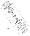
- the body 3 is internally configured with a hollow frustum of cone shape 13, in which a star-shaped structure is contained comprising a multiplicity of tabs 14 (as can be seen more clearly in figure 4) to form a group of tubular ducts to convey the acoustic energy produced by the cone 6 towards the mouth of the flange 2.
- This structure allows pressure (and rarefaction) waves to be obtained having a uniform front on the mouth of the flange 2 in order to avoid disuniformity in acoustic response according to the control frequencies of the voice coil 8 in the operative range of the cone 6.
- the second drive unit for high frequencies is arranged situated above the spider 7 and comprising a block of ferromagnetic material 15 that cooperates with a high-energy disc magnet 16 and a ferromagnetic element 17 to form an annular air gap in which a voice coil 18 of an annular diaphragm 19 can move.
- the annular diaphragm 19 is intended to reproduce the high frequencies of sounds that must be irradiated from the horn speaker.
- said second unit is in the shape of an annular diaphgram with the voice coil arranged on a circle placed between the inner and outer circular perimeter of the annular diaphgram.
- the annular diaphragm 19 can be made with a plastic material like for example mylar, although this does not mean that other materials cannot also be used, as is clear to a person skilled in the art.
- the annular diaphragm 19 cooperates with a structure substantially for guiding sound waves formed from the spacing between an ogive-shaped element 20 and a hollow conical element 21 arranged inside the structure with tabs 14.
- the spacing between the ogive 20 and the element 21 substantially constitutes a revolution sound wave guide that opens out towards the end of the tabs 14 near to the mouth of the control unit 1.
- the frequency responses of the secondary radiator and of the primary radiator are selected with the dimensioning of the mechanical parts, of the rigidity of the cone and of the annular diaphragm to obtain a uniform overall response in the field of frequencies in question.
- the voice coils of the cone and of the annular diaphragm can possibly be controlled through usual power level cross-over and/or signal filters as is known in electro-acoustics.
- Cone diameter mm 110
- Voice coil diameter mm 50
- Material of the cone composite material annular radiator outer diameter: mm 40 inner diameter: mm 25 material: plastic
- Magnetic flux density in the air gap of the cone 2.1
- Magnetic flux density in the air gap of the annular radiator 1.2
- Response in frequency of the cone 300-10000 Hz
- Response in frequency of the annular radiator 8000-20000 Hz
- the ogive-shaped element 20 is formed from a substantially conical-shaped structure 20a that at 20B terminates, instead of in a point in a tear drop shape, and moreover the element 21 is shortened with respect to the corresponding element 21 shown in figure 1.
- a conical element 30 is provided with the base at the annular diaphragm 19, and that mechanically couples in a restricted manner with the element 14, and that terminates in an ogive 31.
- the conical element 30 is equipped with a multiplicity of holes 32 arranged circumferentially and substantially centred at the circumference described by the mobile voice coil of the annular diaphragm 19.
- the holes 32 lead the pressure and rarefaction waves produced by the diaphragm 19 towards the mouth of the drive unit defined in the flange 2.
- the holes 32 instead of being cylindrical are cone-shaped, with the tip of the ideal cone facing towards the annular diaphragm 19 and the base towards the element 14 and therefore the mouth of the drive unit.
Landscapes
- Health & Medical Sciences (AREA)
- Otolaryngology (AREA)
- Physics & Mathematics (AREA)
- Engineering & Computer Science (AREA)
- Acoustics & Sound (AREA)
- Signal Processing (AREA)
- Obtaining Desirable Characteristics In Audible-Bandwidth Transducers (AREA)
- Audible-Bandwidth Dynamoelectric Transducers Other Than Pickups (AREA)
- Fittings On The Vehicle Exterior For Carrying Loads, And Devices For Holding Or Mounting Articles (AREA)
Abstract
Description
- The present invention concerns a coaxial two-way drive unit for horn speakers.
- Horn speakers have been known for a very long time, ever since sound reproduction has been carried out by entirely mechanical means. With the advent of power electronics, technology moved on to electrodynamic speakers of the cone and voice coil type, but the acoustic power that could be irradiated (sounds and/or speaking) could not go beyond certain limits given that this was linked to the size of the speaker cone, which, as its size, and therefore its inertia, increases, and also due to undesired resonance, did not allow an acceptable sounds reproduction.
- Then horn speakers were developed with a control unit formed from a membrane associated with a voice coil, arranged in the throat of the horn. This type of speaker was hugely popular especially in open areas for projecting speeches to the greater public in demonstrations especially before and after the Second World War. This type of speaker does not lend itself very well to the reproduction of music given the wide range of frequencies that are used in music, especially "modern music". During the pre- and post- Second World War period these horn speakers, be they "direct" or folded in various ways, were limited to the reproduction of "speech" in the frequency range of about 300-3000 Hz. A range of this type is totally unsuitable for music.
- Many efforts have been made to improve the power and frequency efficiency of this type of speaker. See for example
US patent 1,715,703 to C.R. Hanna issued on 4 June 1929 , andUS .patent 2, 037, 187 to E.C. Wente issued on 14 April 1936 - In the last few decades there has been a need for electroacoustic systems capable of satisfying requirements of musical fidelity and power irradiated: consider concerts that can have tens of thousands of people, and the individual listener's desire for extremely high acoustic intensities that can even reach the so-called "pain threshold" limits.
- Persons skilled in the art have recognized that an audio frequency range suitable for modern music cannot be reproduced by a single transducer (speaker) and groups of speakers have been developed each of which reproduces a certain range of frequencies, known in the field as "subwoofer, woofer, mid-range, tweeter" and the like.
- The purpose of the present invention is therefore to provide a coaxial two-way drive unit, for horn-loading.
- According to the present invention a two-way drive unit for horn-loading speakers is foreseen, comprising a first voice coil drive unit associated with a second voice coil drive unit; said first unit being frustum of cone shaped; said second unit being in the shape of an annular diaphragm with the voice coil arranged on a circle placed between the inner and outer circular perimeter of the annular diaphragm; the first drive unit being associated with a truncated segmented substantially conical element, with a first end facing towards the cone and a second tapered end facing towards the mouth of the drive unit; the second drive unit being associated with a substantially ogive-shaped element cooperating with said conical element and facing towards the mouth of the drive unit; the first and second drive unit being associated with a respective magnetic structure preferably having a permanent magnet that defines a first and a second air gap cooperating with the voice coil of the cone-shaped element and with the voice coil of the annular diaphragm shaped element.
- Other characteristics, constructive details and operative features are outlined in the claims and shall become clear from the following description, with reference to the figures of the attached drawings in which the same reference numerals indicate corresponding parts and in which:
- figure 1 shows a partially sectioned view of the coaxial two-way drive unit, according to the present invention;
- figure 2 shows an enlarged partial section view of the part of the drive unit of figure 1 that highlights the annular diaphragm and the relative horn structure;
- figure 3 shows a further enlarged partial section view of the annular radiator shown in figures 1 and 2;
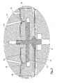
- figure 4 shows an exploded perspective view of the components of the drive unit illustrated in the previous figures;
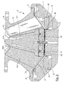
- figure 5 shows a first variant, partially sectioned of the coaxial two-way drive unit, as shown in figures 1 to 4;
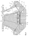
- figure 6 shows a second variant, partially sectioned of the coaxial two-way drive unit, as shown in figures 1 to 4, and
- figure 7 shows an exploded perspective view of the components of the modified drive unit, shown in figure 6.
- With reference to the figures, and in particular figure 1, the drive unit for horn speakers comprises a
body 1 equipped with aflange 2 for mechanical coupling with a horn structure, not shown and of the conventional type. - The
body 1 comprises afirst part 3 and asecond base part 4 joined together throughscrews 5. The rim of a speaker cone 6, which can be made from various materials, is locked between thepart 3 and thepart 4 and is associated with aspider 7. In the joining point between the cone 6 and the spider 7 a cylindrical voice coil 8 is arranged that is axially mobile in an air gap formed from ablock 9 and from theannular pole piece 10 that together define an air gap. In the air gap there is a magnetic field preferably produced by amagnet 12, which can be of the high-energy type (for example one or more magnets of the neodymium, samarium-cobalt and similar types introduced into technology relatively recently). - It is clear to a person skilled in the art that the cone 6 is not necessarily a cone of Euclidean geometry, but that it could take up configurations that deviate from that of a pure geometrical cone as is well known in the field of speakers and of excitation membranes of drive units for horn speakers.
- The
body 3 is internally configured with a hollow frustum ofcone shape 13, in which a star-shaped structure is contained comprising a multiplicity of tabs 14 (as can be seen more clearly in figure 4) to form a group of tubular ducts to convey the acoustic energy produced by the cone 6 towards the mouth of theflange 2. - This structure allows pressure (and rarefaction) waves to be obtained having a uniform front on the mouth of the
flange 2 in order to avoid disuniformity in acoustic response according to the control frequencies of the voice coil 8 in the operative range of the cone 6. - In the housing formed from the inner part of the structure with
tabs 14 the second drive unit for high frequencies is arranged situated above thespider 7 and comprising a block offerromagnetic material 15 that cooperates with a high-energy disc magnet 16 and aferromagnetic element 17 to form an annular air gap in which avoice coil 18 of anannular diaphragm 19 can move. Theannular diaphragm 19 is intended to reproduce the high frequencies of sounds that must be irradiated from the horn speaker. - In other words, said second unit is in the shape of an annular diaphgram with the voice coil arranged on a circle placed between the inner and outer circular perimeter of the annular diaphgram.
- The
annular diaphragm 19 can be made with a plastic material like for example mylar, although this does not mean that other materials cannot also be used, as is clear to a person skilled in the art. - The
annular diaphragm 19 cooperates with a structure substantially for guiding sound waves formed from the spacing between an ogive-shaped element 20 and a hollowconical element 21 arranged inside the structure withtabs 14. - The spacing between the
ogive 20 and theelement 21 substantially constitutes a revolution sound wave guide that opens out towards the end of thetabs 14 near to the mouth of thecontrol unit 1. - The frequency responses of the secondary radiator and of the primary radiator are selected with the dimensioning of the mechanical parts, of the rigidity of the cone and of the annular diaphragm to obtain a uniform overall response in the field of frequencies in question. The voice coils of the cone and of the annular diaphragm can possibly be controlled through usual power level cross-over and/or signal filters as is known in electro-acoustics.
- As a non-limiting example, the following data relating to a construction according to the present invention is shown:
Cone diameter: mm 110 Voice coil diameter: mm 50 Material of the cone: composite material annular radiator outer diameter: mm 40 inner diameter: mm 25 material: plastic Magnetic flux density in the air gap of the cone: 2.1 T Magnetic flux density in the air gap of the annular radiator: 1.2 T Response in frequency of the cone: 300-10000 Hz Response in frequency of the annular radiator: 8000-20000 Hz Deviation from linearity of response in frequency: +/-02 dB - With reference to figure 5, a first variant of the structure illustrated in reference to figures 1 to 4 shall now be described.
- As can be seen from figure 5, the ogive-
shaped element 20 is formed from a substantially conical-shaped structure 20a that at 20B terminates, instead of in a point in a tear drop shape, and moreover theelement 21 is shortened with respect to thecorresponding element 21 shown in figure 1. - The rest of the construction shown in figure 5 is identical to the one shown in the previous figures and therefore we shall not make a detailed description thereof.
- Now with reference to figures 6 and 7, a further modification of the construction according to the present invention shall be illustrated.
- As can be seen in figures 6 and 7, a
conical element 30 is provided with the base at theannular diaphragm 19, and that mechanically couples in a restricted manner with theelement 14, and that terminates in anogive 31. - As can be seen in figure 6 and 7, the
conical element 30 is equipped with a multiplicity ofholes 32 arranged circumferentially and substantially centred at the circumference described by the mobile voice coil of theannular diaphragm 19. - The
holes 32 lead the pressure and rarefaction waves produced by thediaphragm 19 towards the mouth of the drive unit defined in theflange 2. - In a further variant that is not shown, the
holes 32 instead of being cylindrical are cone-shaped, with the tip of the ideal cone facing towards theannular diaphragm 19 and the base towards theelement 14 and therefore the mouth of the drive unit.
Claims (11)
- A coaxial two-way drive unit (1) for horn-loading speakers, characterised in that it comprises a first voice coil drive unit (6, 8) associated with a second voice coil drive unit (18, 19); said first unit being frustum of cone shaped; said second unit being shaped like an annular diaphragm (19) with the voice coil (18) arranged on a circle placed between the inner and outer circular perimeter of said annular diaphragm (19); said first drive unit (6) being associated with a truncated segmented substantially conical element (3), with a first end facing towards the cone and a second tapered end facing towards the mouth of the drive unit (1); said second drive unit being associated with an ogive-shaped element (20, 31) cooperating with said substantially conical element and facing towards the mouth of the drive unit; said first and second drive units (6, 19) being associated with a respective magnetic structure with high-energy permanent magnets that define a first and a second air gap cooperating with the voice coil (8) of said cone-shaped element (6) and with the voice coil (18) of said annular diaphragm-shaped element (19).
- A drive unit according to claim 1, characterised in that said segmented conical element (3) comprises a plurality of circumferentially arranged tabs (14).
- A drive unit according to claim 1 or 2, characterised in that said segmented conical element (3) has a part of greater diameter facing towards said cone (6) and a part of smaller diameter facing towards the outlet mouth of said drive unit (1).
- A drive unit according to anyone of the previous claims, characterised in that said ogive-shaped element (20, 31) has a tapered tip facing towards the mouth of said drive unit (1).
- A drive unit according to anyone of claims 1 to 4, characterised in that said ogive-shaped element (20, 36) has a substantially tear drop (20a, 20b) configuration arranged at the mouth of said drive unit (1).
- A drive unit according to one or more of claims 1 to 4, characterised in that said ogive-shaped element (20, 36) is equipped with a plurality of holes (32) arranged circumferentially substantially in register with said annular diaphragm.
- A drive unit according to claim 6, characterised in that said holes (32) are cylindrical.
- A drive unit according to claim 6, characterised in that said holes (32) are conical with the "apex" facing towards said annular diaphragm and the "base" facing towards said mouth.
- A drive unit according to claims 1 to 4, characterised in that said ogive-shaped element (20) and said substantially conical element with tabs (14) define a substantially annular wave guide that starts from said annular diaphragm (19) and opens out towards said mouth.
- A drive unit according to anyone of the previous claims, characterised in that said cone-shaped element (6) can be made from various materials (plastics, metals, composites, etc.).
- A drive unit according to anyone of claims 1 to 10, characterised in that said annular diaphragm (19) can be made from various materials (plastics, metals, composites, etc.).
Applications Claiming Priority (1)
| Application Number | Priority Date | Filing Date | Title |
|---|---|---|---|
| ITAO20050155 | 2005-07-15 |
Publications (3)
| Publication Number | Publication Date |
|---|---|
| EP1755357A2 true EP1755357A2 (en) | 2007-02-21 |
| EP1755357A3 EP1755357A3 (en) | 2007-03-21 |
| EP1755357B1 EP1755357B1 (en) | 2008-09-24 |
Family
ID=37606962
Family Applications (1)
| Application Number | Title | Priority Date | Filing Date |
|---|---|---|---|
| EP06117048A Not-in-force EP1755357B1 (en) | 2005-07-15 | 2006-07-12 | Coaxial two-way drive unit for horn speakers |
Country Status (3)
| Country | Link |
|---|---|
| EP (1) | EP1755357B1 (en) |
| AT (1) | ATE409396T1 (en) |
| DE (1) | DE602006002852D1 (en) |
Cited By (5)
| Publication number | Priority date | Publication date | Assignee | Title |
|---|---|---|---|---|
| GB2458275A (en) * | 2008-03-10 | 2009-09-16 | Turbosound Ltd | Horn loading arrangement for a co-axial two-way loudspeaker |
| WO2011086300A1 (en) * | 2010-01-15 | 2011-07-21 | Phl Audio | Coaxial speaker system having a compression chamber with a horn |
| GB2502189A (en) * | 2013-03-25 | 2013-11-20 | Tannoy Ltd | Magnetic assembly for a co-axial loudspeaker |
| US8989429B2 (en) | 2010-01-15 | 2015-03-24 | Phl Audio | Electrodynamic transducer having a dome and a buoyant hanging part |
| US9042594B2 (en) | 2010-01-15 | 2015-05-26 | Phl Audio | Electrodynamic transducer having a dome and an inner hanging part |
Family Cites Families (4)
| Publication number | Priority date | Publication date | Assignee | Title |
|---|---|---|---|---|
| GB545712A (en) * | 1941-01-02 | 1942-06-09 | Albert Charles Woods | Improvements in and relating to loud speakers |
| US3665124A (en) * | 1968-12-30 | 1972-05-23 | Nippon Musical Instruments Mfg | Loudspeaker having annular diaphragm with double voice coil |
| GB9407101D0 (en) * | 1994-04-09 | 1994-06-01 | Harman Motive Ltd | A modular tweeter |
| JP3701779B2 (en) * | 1997-09-19 | 2005-10-05 | ティーオーエー株式会社 | Coaxial speakers |
-
2006
- 2006-07-12 AT AT06117048T patent/ATE409396T1/en not_active IP Right Cessation
- 2006-07-12 EP EP06117048A patent/EP1755357B1/en not_active Not-in-force
- 2006-07-12 DE DE602006002852T patent/DE602006002852D1/en not_active Expired - Fee Related
Cited By (13)
| Publication number | Priority date | Publication date | Assignee | Title |
|---|---|---|---|---|
| GB2458275A (en) * | 2008-03-10 | 2009-09-16 | Turbosound Ltd | Horn loading arrangement for a co-axial two-way loudspeaker |
| US9084056B2 (en) | 2010-01-15 | 2015-07-14 | Phl Audio | Coaxial speaker system having a compression chamber with a horn |
| WO2011086299A1 (en) * | 2010-01-15 | 2011-07-21 | Phl Audio | Coaxial speaker system having a compression chamber |
| FR2955444A1 (en) * | 2010-01-15 | 2011-07-22 | Phl Audio | COAXIAL SPEAKER SYSTEM WITH COMPRESSION CHAMBER |
| CN102907115A (en) * | 2010-01-15 | 2013-01-30 | Phl音响公司 | Coaxial speaker system having a compression chamber with a horn |
| US8989429B2 (en) | 2010-01-15 | 2015-03-24 | Phl Audio | Electrodynamic transducer having a dome and a buoyant hanging part |
| US9042594B2 (en) | 2010-01-15 | 2015-05-26 | Phl Audio | Electrodynamic transducer having a dome and an inner hanging part |
| WO2011086300A1 (en) * | 2010-01-15 | 2011-07-21 | Phl Audio | Coaxial speaker system having a compression chamber with a horn |
| CN102907115B (en) * | 2010-01-15 | 2015-12-09 | Phl音响公司 | There is the coaxial loudspeaker system of at least two-way |
| US9232301B2 (en) | 2010-01-15 | 2016-01-05 | Phl Audio | Coaxial speaker system having a compression chamber |
| GB2502189A (en) * | 2013-03-25 | 2013-11-20 | Tannoy Ltd | Magnetic assembly for a co-axial loudspeaker |
| GB2502189B (en) * | 2013-03-25 | 2014-06-04 | Tannoy Ltd | Loudspeaker |
| US9271071B2 (en) | 2013-03-25 | 2016-02-23 | Music Group Innovation Sc Ltd. | Loudspeaker |
Also Published As
| Publication number | Publication date |
|---|---|
| ATE409396T1 (en) | 2008-10-15 |
| DE602006002852D1 (en) | 2008-11-06 |
| EP1755357A3 (en) | 2007-03-21 |
| EP1755357B1 (en) | 2008-09-24 |
Similar Documents
| Publication | Publication Date | Title |
|---|---|---|
| CN110178383B (en) | High-resolution electromagnetic loudspeaker with bridge-edge method | |
| US8611583B2 (en) | Compact coaxial crossover-free loudspeaker | |
| JP2009543512A (en) | High frequency diaphragm and voice coil assembly | |
| JP6286151B2 (en) | Loudspeaker driver with dual electromagnetic assembly | |
| US20040161129A1 (en) | Low profile speaker and system | |
| US20040202342A1 (en) | Compound loudspeaker drive unit having a magnet system | |
| US20050175208A1 (en) | Audio speaker system employing an annular gasket separating a horn waveguide from a sound reproducing membrane | |
| JP2023024716A (en) | Electroacoustic transducer | |
| CN110169084A (en) | Ultra-thin high-resolution electromagnetic speaker with bridge-shaped edge method | |
| EP1755357B1 (en) | Coaxial two-way drive unit for horn speakers | |
| US20070098209A1 (en) | Integrated multi yoke for multi polar loudspeakers | |
| JP2019047464A (en) | Speaker system | |
| CN201252635Y (en) | Double-frequency coaxial earphone with shared magnet | |
| US20070160256A1 (en) | Coaxial two-way drive unit for horn speakers | |
| JP2000138996A (en) | Speaker device | |
| US1634292A (en) | Art of the transmission of sound | |
| CN211089944U (en) | A dustproof cap and sound generating mechanism for sound generating mechanism | |
| JPH06217390A (en) | Speaker and speaker system | |
| KR100267956B1 (en) | Horn speaker | |
| JP2007318346A (en) | Manufacturing method of speaker device, speaker device, and assembling tool for speaker device | |
| JP2020031405A (en) | Speaker system | |
| JP2000138997A (en) | Speaker device | |
| KR100724006B1 (en) | Speaker structure | |
| US20080101647A1 (en) | Full-range speaker device | |
| KR200387749Y1 (en) | full range speaker |
Legal Events
| Date | Code | Title | Description |
|---|---|---|---|
| PUAI | Public reference made under article 153(3) epc to a published international application that has entered the european phase |
Free format text: ORIGINAL CODE: 0009012 |
|
| PUAL | Search report despatched |
Free format text: ORIGINAL CODE: 0009013 |
|
| AK | Designated contracting states |
Kind code of ref document: A2 Designated state(s): AT BE BG CH CY CZ DE DK EE ES FI FR GB GR HU IE IS IT LI LT LU LV MC NL PL PT RO SE SI SK TR |
|
| AX | Request for extension of the european patent |
Extension state: AL BA HR MK YU |
|
| AK | Designated contracting states |
Kind code of ref document: A3 Designated state(s): AT BE BG CH CY CZ DE DK EE ES FI FR GB GR HU IE IS IT LI LT LU LV MC NL PL PT RO SE SI SK TR |
|
| AX | Request for extension of the european patent |
Extension state: AL BA HR MK YU |
|
| RIC1 | Information provided on ipc code assigned before grant |
Ipc: H04R 1/24 20060101AFI20070214BHEP Ipc: H04R 1/30 20060101ALI20070214BHEP |
|
| 17P | Request for examination filed |
Effective date: 20070424 |
|
| AKX | Designation fees paid |
Designated state(s): AT BE BG CH CY CZ DE DK EE ES FI FR GB GR HU IE IS IT LI LT LU LV MC NL PL PT RO SE SI SK TR |
|
| GRAP | Despatch of communication of intention to grant a patent |
Free format text: ORIGINAL CODE: EPIDOSNIGR1 |
|
| GRAS | Grant fee paid |
Free format text: ORIGINAL CODE: EPIDOSNIGR3 |
|
| GRAA | (expected) grant |
Free format text: ORIGINAL CODE: 0009210 |
|
| AK | Designated contracting states |
Kind code of ref document: B1 Designated state(s): AT BE BG CH CY CZ DE DK EE ES FI FR GB GR HU IE IS IT LI LT LU LV MC NL PL PT RO SE SI SK TR |
|
| REG | Reference to a national code |
Ref country code: GB Ref legal event code: FG4D |
|
| REG | Reference to a national code |
Ref country code: CH Ref legal event code: EP |
|
| REG | Reference to a national code |
Ref country code: IE Ref legal event code: FG4D |
|
| REF | Corresponds to: |
Ref document number: 602006002852 Country of ref document: DE Date of ref document: 20081106 Kind code of ref document: P |
|
| PG25 | Lapsed in a contracting state [announced via postgrant information from national office to epo] |
Ref country code: LT Free format text: LAPSE BECAUSE OF FAILURE TO SUBMIT A TRANSLATION OF THE DESCRIPTION OR TO PAY THE FEE WITHIN THE PRESCRIBED TIME-LIMIT Effective date: 20080924 |
|
| PG25 | Lapsed in a contracting state [announced via postgrant information from national office to epo] |
Ref country code: LV Free format text: LAPSE BECAUSE OF FAILURE TO SUBMIT A TRANSLATION OF THE DESCRIPTION OR TO PAY THE FEE WITHIN THE PRESCRIBED TIME-LIMIT Effective date: 20080924 Ref country code: SI Free format text: LAPSE BECAUSE OF FAILURE TO SUBMIT A TRANSLATION OF THE DESCRIPTION OR TO PAY THE FEE WITHIN THE PRESCRIBED TIME-LIMIT Effective date: 20080924 Ref country code: FI Free format text: LAPSE BECAUSE OF FAILURE TO SUBMIT A TRANSLATION OF THE DESCRIPTION OR TO PAY THE FEE WITHIN THE PRESCRIBED TIME-LIMIT Effective date: 20080924 Ref country code: AT Free format text: LAPSE BECAUSE OF FAILURE TO SUBMIT A TRANSLATION OF THE DESCRIPTION OR TO PAY THE FEE WITHIN THE PRESCRIBED TIME-LIMIT Effective date: 20080924 |
|
| NLV1 | Nl: lapsed or annulled due to failure to fulfill the requirements of art. 29p and 29m of the patents act | ||
| PG25 | Lapsed in a contracting state [announced via postgrant information from national office to epo] |
Ref country code: BE Free format text: LAPSE BECAUSE OF FAILURE TO SUBMIT A TRANSLATION OF THE DESCRIPTION OR TO PAY THE FEE WITHIN THE PRESCRIBED TIME-LIMIT Effective date: 20080924 |
|
| PG25 | Lapsed in a contracting state [announced via postgrant information from national office to epo] |
Ref country code: ES Free format text: LAPSE BECAUSE OF FAILURE TO SUBMIT A TRANSLATION OF THE DESCRIPTION OR TO PAY THE FEE WITHIN THE PRESCRIBED TIME-LIMIT Effective date: 20090104 Ref country code: BG Free format text: LAPSE BECAUSE OF FAILURE TO SUBMIT A TRANSLATION OF THE DESCRIPTION OR TO PAY THE FEE WITHIN THE PRESCRIBED TIME-LIMIT Effective date: 20081224 |
|
| PG25 | Lapsed in a contracting state [announced via postgrant information from national office to epo] |
Ref country code: PT Free format text: LAPSE BECAUSE OF FAILURE TO SUBMIT A TRANSLATION OF THE DESCRIPTION OR TO PAY THE FEE WITHIN THE PRESCRIBED TIME-LIMIT Effective date: 20090224 Ref country code: NL Free format text: LAPSE BECAUSE OF FAILURE TO SUBMIT A TRANSLATION OF THE DESCRIPTION OR TO PAY THE FEE WITHIN THE PRESCRIBED TIME-LIMIT Effective date: 20080924 Ref country code: IS Free format text: LAPSE BECAUSE OF FAILURE TO SUBMIT A TRANSLATION OF THE DESCRIPTION OR TO PAY THE FEE WITHIN THE PRESCRIBED TIME-LIMIT Effective date: 20090124 Ref country code: CZ Free format text: LAPSE BECAUSE OF FAILURE TO SUBMIT A TRANSLATION OF THE DESCRIPTION OR TO PAY THE FEE WITHIN THE PRESCRIBED TIME-LIMIT Effective date: 20080924 Ref country code: SK Free format text: LAPSE BECAUSE OF FAILURE TO SUBMIT A TRANSLATION OF THE DESCRIPTION OR TO PAY THE FEE WITHIN THE PRESCRIBED TIME-LIMIT Effective date: 20080924 Ref country code: RO Free format text: LAPSE BECAUSE OF FAILURE TO SUBMIT A TRANSLATION OF THE DESCRIPTION OR TO PAY THE FEE WITHIN THE PRESCRIBED TIME-LIMIT Effective date: 20080924 |
|
| PG25 | Lapsed in a contracting state [announced via postgrant information from national office to epo] |
Ref country code: DK Free format text: LAPSE BECAUSE OF FAILURE TO SUBMIT A TRANSLATION OF THE DESCRIPTION OR TO PAY THE FEE WITHIN THE PRESCRIBED TIME-LIMIT Effective date: 20080924 Ref country code: EE Free format text: LAPSE BECAUSE OF FAILURE TO SUBMIT A TRANSLATION OF THE DESCRIPTION OR TO PAY THE FEE WITHIN THE PRESCRIBED TIME-LIMIT Effective date: 20080924 |
|
| PLBE | No opposition filed within time limit |
Free format text: ORIGINAL CODE: 0009261 |
|
| STAA | Information on the status of an ep patent application or granted ep patent |
Free format text: STATUS: NO OPPOSITION FILED WITHIN TIME LIMIT |
|
| PG25 | Lapsed in a contracting state [announced via postgrant information from national office to epo] |
Ref country code: IT Free format text: LAPSE BECAUSE OF FAILURE TO SUBMIT A TRANSLATION OF THE DESCRIPTION OR TO PAY THE FEE WITHIN THE PRESCRIBED TIME-LIMIT Effective date: 20080924 |
|
| 26N | No opposition filed |
Effective date: 20090625 |
|
| PG25 | Lapsed in a contracting state [announced via postgrant information from national office to epo] |
Ref country code: SE Free format text: LAPSE BECAUSE OF FAILURE TO SUBMIT A TRANSLATION OF THE DESCRIPTION OR TO PAY THE FEE WITHIN THE PRESCRIBED TIME-LIMIT Effective date: 20081224 |
|
| PG25 | Lapsed in a contracting state [announced via postgrant information from national office to epo] |
Ref country code: MC Free format text: LAPSE BECAUSE OF NON-PAYMENT OF DUE FEES Effective date: 20090731 |
|
| REG | Reference to a national code |
Ref country code: FR Ref legal event code: ST Effective date: 20100331 |
|
| REG | Reference to a national code |
Ref country code: IE Ref legal event code: MM4A |
|
| PG25 | Lapsed in a contracting state [announced via postgrant information from national office to epo] |
Ref country code: FR Free format text: LAPSE BECAUSE OF NON-PAYMENT OF DUE FEES Effective date: 20090731 |
|
| PG25 | Lapsed in a contracting state [announced via postgrant information from national office to epo] |
Ref country code: PL Free format text: LAPSE BECAUSE OF FAILURE TO SUBMIT A TRANSLATION OF THE DESCRIPTION OR TO PAY THE FEE WITHIN THE PRESCRIBED TIME-LIMIT Effective date: 20080924 |
|
| PG25 | Lapsed in a contracting state [announced via postgrant information from national office to epo] |
Ref country code: DE Free format text: LAPSE BECAUSE OF NON-PAYMENT OF DUE FEES Effective date: 20100202 |
|
| PG25 | Lapsed in a contracting state [announced via postgrant information from national office to epo] |
Ref country code: IE Free format text: LAPSE BECAUSE OF NON-PAYMENT OF DUE FEES Effective date: 20090712 |
|
| PG25 | Lapsed in a contracting state [announced via postgrant information from national office to epo] |
Ref country code: GR Free format text: LAPSE BECAUSE OF FAILURE TO SUBMIT A TRANSLATION OF THE DESCRIPTION OR TO PAY THE FEE WITHIN THE PRESCRIBED TIME-LIMIT Effective date: 20081225 |
|
| REG | Reference to a national code |
Ref country code: CH Ref legal event code: PL |
|
| GBPC | Gb: european patent ceased through non-payment of renewal fee |
Effective date: 20100712 |
|
| PG25 | Lapsed in a contracting state [announced via postgrant information from national office to epo] |
Ref country code: LU Free format text: LAPSE BECAUSE OF NON-PAYMENT OF DUE FEES Effective date: 20090712 Ref country code: CH Free format text: LAPSE BECAUSE OF NON-PAYMENT OF DUE FEES Effective date: 20100731 Ref country code: LI Free format text: LAPSE BECAUSE OF NON-PAYMENT OF DUE FEES Effective date: 20100731 |
|
| PG25 | Lapsed in a contracting state [announced via postgrant information from national office to epo] |
Ref country code: HU Free format text: LAPSE BECAUSE OF FAILURE TO SUBMIT A TRANSLATION OF THE DESCRIPTION OR TO PAY THE FEE WITHIN THE PRESCRIBED TIME-LIMIT Effective date: 20090325 |
|
| PG25 | Lapsed in a contracting state [announced via postgrant information from national office to epo] |
Ref country code: GB Free format text: LAPSE BECAUSE OF NON-PAYMENT OF DUE FEES Effective date: 20100712 |
|
| PG25 | Lapsed in a contracting state [announced via postgrant information from national office to epo] |
Ref country code: TR Free format text: LAPSE BECAUSE OF FAILURE TO SUBMIT A TRANSLATION OF THE DESCRIPTION OR TO PAY THE FEE WITHIN THE PRESCRIBED TIME-LIMIT Effective date: 20080924 |
|
| PG25 | Lapsed in a contracting state [announced via postgrant information from national office to epo] |
Ref country code: CY Free format text: LAPSE BECAUSE OF FAILURE TO SUBMIT A TRANSLATION OF THE DESCRIPTION OR TO PAY THE FEE WITHIN THE PRESCRIBED TIME-LIMIT Effective date: 20080924 |