EP1755095B1 - Method and apparatus for damping vibrations in a motion simulation platform - Google Patents
Method and apparatus for damping vibrations in a motion simulation platform Download PDFInfo
- Publication number
- EP1755095B1 EP1755095B1 EP06254240.2A EP06254240A EP1755095B1 EP 1755095 B1 EP1755095 B1 EP 1755095B1 EP 06254240 A EP06254240 A EP 06254240A EP 1755095 B1 EP1755095 B1 EP 1755095B1
- Authority
- EP
- European Patent Office
- Prior art keywords
- damping unit
- platform
- lateral
- vibrations
- plate
- Prior art date
- Legal status (The legal status is an assumption and is not a legal conclusion. Google has not performed a legal analysis and makes no representation as to the accuracy of the status listed.)
- Active
Links
Images


Classifications
-
- G—PHYSICS
- G09—EDUCATION; CRYPTOGRAPHY; DISPLAY; ADVERTISING; SEALS
- G09B—EDUCATIONAL OR DEMONSTRATION APPLIANCES; APPLIANCES FOR TEACHING, OR COMMUNICATING WITH, THE BLIND, DEAF OR MUTE; MODELS; PLANETARIA; GLOBES; MAPS; DIAGRAMS
- G09B9/00—Simulators for teaching or training purposes
- G09B9/02—Simulators for teaching or training purposes for teaching control of vehicles or other craft
-
- G—PHYSICS
- G09—EDUCATION; CRYPTOGRAPHY; DISPLAY; ADVERTISING; SEALS
- G09B—EDUCATIONAL OR DEMONSTRATION APPLIANCES; APPLIANCES FOR TEACHING, OR COMMUNICATING WITH, THE BLIND, DEAF OR MUTE; MODELS; PLANETARIA; GLOBES; MAPS; DIAGRAMS
- G09B9/00—Simulators for teaching or training purposes
-
- G—PHYSICS
- G09—EDUCATION; CRYPTOGRAPHY; DISPLAY; ADVERTISING; SEALS
- G09B—EDUCATIONAL OR DEMONSTRATION APPLIANCES; APPLIANCES FOR TEACHING, OR COMMUNICATING WITH, THE BLIND, DEAF OR MUTE; MODELS; PLANETARIA; GLOBES; MAPS; DIAGRAMS
- G09B9/00—Simulators for teaching or training purposes
- G09B9/02—Simulators for teaching or training purposes for teaching control of vehicles or other craft
- G09B9/08—Simulators for teaching or training purposes for teaching control of vehicles or other craft for teaching control of aircraft, e.g. Link trainer
- G09B9/12—Motion systems for aircraft simulators
Definitions
- the present invention relates to moveable platforms, particularly platforms of motion simulators, and more particularly to the damping of vibrations in such platforms.
- Motion simulators are used for a variety of purposes, including entertainment and flight simulation for example, and usually comprise an upper platform which is mounted for movement relative to a fixed lower base and is operatively connected thereto by a plurality of actuators which move the platform as required in a desired number of degrees of freedom.
- undesirable vibrations are required to be limited as much as possible in order to minimize audible noise and wear of the simulator parts.
- unwanted vibrations felt by the pilot can result in un-realistic representations of the performance and feel of the true airplane or helicopter.
- such a flight simulator must nonetheless reproduce certain vibrations which are true to those experienced in the actual aircraft, such as certain low frequency vibrations for example.
- hydraulic actuators are used, as opposed to other types of linear actuators, as these actuators are well proven and produce minimal undesirable vibrations.
- hydraulic actuators present several disadvantages, among which are a high maintenance requirement, the need for costly and noisy accessory equipment such as pumps, hosing and the like, the risk of contamination or leakage of the hydraulic fluid, and a low energy efficiency.
- Electromechanical linear actuators require less maintenance than hydraulic actuators, and are generally less complex and costly to operate.
- electromechanical linear actuators have proved to date unable to cost-effectively reproduce the performance of their hydraulic counterparts, as many electromechanical linear actuators produce more undesirable vibrations, which are ultimately transferred to the motion platform and therefore the user therein, causing an elevated audible noise level in the motion cabin and a reduced life of the actuated equipment as a result of the additional vibrations.
- Flight simulators incorporating pneumatic or hydraulic damping systems are known, and typically attempt to reduce all transmitted vibrations by reducing the actuator load. Such damping systems are generally complex, costly and include a high number of parts which further augments the risk of equipment failure.
- control systems are necessary to prevent a failure of the damping system from damaging the motion simulator cabin or endangering a user of the motion simulator.
- US 6,022,005 discloses a semi-active vibration isolator and a fine positioning mount for reducing vibrational disturbances on a payload platform. This document is generally concerned with isolating optics from any vibration that is present in a base platform on which the optics or other precision equipment is to be mounted.
- US 2003/0168295 discloses a vibration isolation system with an actuator having two nested, relatively movable members, and a magnetostrictive member coupled to both nested members. A variable strength magnetic field is applied to the magnetostrictive member to control the relative positions of the two nesting members.
- US 6,315,094 discloses a virtual skyhook vibration isolation system that is intended to reduce transmissibility at a resonance frequency.
- a damping unit for an actuated motion platform including: a plate having a top surface, a bottom surface and opposed lateral plate surfaces, the bottom surface being adapted to be rigidly connected to a vibration source; the opposed lateral plate surfaces being disposed between the top surface and the bottom surface, the lateral plate surfaces including lateral projections, the lateral projections each having a top surface, a bottom surface, and at least three lateral surfaces; lateral mounting supports each receiving at least one of said lateral projections and being adapted for rigid fastening to the motion platform; a first resilient member overlying at least a portion of said top surface of said plate and being retained between the top surface and the motion platform by said lateral mounting supports, said first resilient member providing vibration absorption such as to limit vibrations transmitted from said plate to said motion platform in at least a direction substantially perpendicular to said top surface; two second resilient members, each of the two second resilient members being disposed between the at least three lateral surfaces of
- a multiple degree-of-freedom motion simulator assembly comprising:
- an electromechanical linear actuator for a motion simulator system having a motion platform displaceable in multiple degrees-of-freedom relative to a fixed base by at least one said actuator, the electromechanical linear actuator comprising:
- a motion system 10 for a displaceable motion platform such as that of a motion simulator, of the type commonly known as a Stewart platform is shown.
- the platform assembly 10 includes a base formed of three base plates portions 12 fixed to an underlying support surface and therefore fixed relative to one another, six mobile and extensible legs or actuators 16 which have lower ends thereof engaged to the base plate portions 12 and opposed upper ends engaged to at least three bearing block assemblies 14 which support the moving platform of the motion simulator cabin.
- Such a motion system 10 is used to displace a motion simulator 50, such as that depicted in Fig. 5 , which generally includes a simulator cabin 51 mounted on a displaceable motion platform 52.
- the motion platform 52 is displaced and controlled by linear actuators 16 such as those of the motion system 10.
- the vibration damping units 30 of the present invention which will be described in further detail below, are disposed between the upper ends of each of the actuators 16 and the motion platform 52, and more precisely between the bearing blocks 14, to which the actuators 16 are pivotably engaged, and the motion platform 52.
- Each of the actuators 16 is preferably a linear actuator and includes a first universal joint 18 on one (lower) end and a second universal joint 19 on the opposed (upper) end.
- the first universal joint 18 is operably connected to one of the base plate portions 12, and the second universal joint 19 is connected to one of the bearing blocks 14.
- Each of the platform's six linear actuators 16 has two relatively telescoping parts, with a piston-like degree of freedom therebetween.
- the six linear actuators 16 with the universal joints 18,19 on either end thereof provide the platform supported by the bearing block assemblies 14 with six degrees of freedom, three rotational and three translational.
- Each base plate 12 has the lower ends of two actuators 16 mounted thereto, each of these same two actuators being engaged at their upper ends to different bearing blocks 14.
- each actuator 16 is connected to a bearing block 14 along with a first adjacent actuator, and to a base portion along with a second adjacent actuator.
- Such a configuration allows the platform to move with respect to the base about six degrees of freedom.
- the actuators 16 are linear actuators, and more preferably electromechanical actuators. Although the present invention will be generally described with respect to its use with electromechanical linear actuators, it is to be understood that other suitable types of linear actuators, such as hydraulic actuators for example, can also be used.
- Each electromechanical linear actuator 16 may be of a known type and as such includes a drive mechanism, which may include an electric motor 20 having a rotatable output shaft (not shown), an outer tube or cylindrical member 22 surrounding a lead screw (not shown) connected to the output shaft, an extensible inner tube or cylindrical member 24 containing an internal nut (not shown) engaged with the lead screw such that turning of the screw by the motor 20 extends or retracts the inner tube 24 which acts as the outer extensible end of the actuator, and a position feedback transducer 26 to determine the position of the inner cylindrical member 24 with respect to the outer cylindrical member 22.
- a drive mechanism which may include an electric motor 20 having a rotatable output shaft (not shown), an outer tube or cylindrical member 22 surrounding a lead screw (not shown) connected to the output shaft, an extensible inner tube or cylindrical member 24 containing an internal nut (not shown) engaged with the lead screw such that turning of the screw by the motor 20 extends or retracts the inner tube 24 which acts as the outer extensible end of the actuator, and a position
- electromechanical linear actuators depicted and described herein are but one type of such electrically-powered linear actuators which can be employed with the vibration damping unit of the present invention, and it is to be understood that other varieties of electromechanical linear actuators can be similarly used.
- such alternate electrically-powered linear actuators could have side mounted motors, rather than the inline type depicted herein, or other drive mechanisms such as those which are belt and/or gear driven. While several advantages exist with all such electromechanical actuators 16, they generally generate more vibrations than comparative hydraulic actuators which particularly causes, among other things, undesirable audible noise. As such, additional damping of such vibrations is necessary for applications in which undue additional vibrations, particularly vibrations causing audible noise, are undesirable.
- the selective vibration damping unit 30 is shown.
- the damping unit 30 is engaged with each of the bearing block 14, preferably being located between the bearing blocks 14 and the superimposed motion simulator platform supported thereby, in order to isolate the platform from unwanted vibrations produced by the linear actuators 16.
- the vibration damping unit 30 is mounted to a flat upper surface 28 of each of the bearing blocks 14.
- Portions of the damping unit 30, as will be described in further detail below, are in turn fastened to an underside of the motion platform.
- each of the damping units 30 acts to vibrationally isolate the motion platform which is mounted to the bearing blocks 14 of the motion system.
- the vibration damping unit 30 generally comprises at least a lower "floating" bearing plate 32, resilient members 36 and 37 generally disposed on all sides of at least a portion of the bearing plate 32, and lateral mounting supports 42 retaining the assembly together and used to mount the damping unit to the motion platform.
- an upper mounting plate 44 is also preferably provided above the upper resilient member 36.
- the damping unit 30 is shown mounted to the upper surface 28 of the bearing block 14, to which the upper ends of the two adjacent linear actuators 16 are engaged via the universal joints 19.
- the upper mounting plate 44 and one of the two opposed lateral mounting supports 42 have been removed for clarity.
- the universal joints 19 at the upper ends of the linear actuators 16 are mounted to the bearing block 14 as depicted in a cantilevered type manner, wherein the longitudinal axes of the linear actuators are offset relative to the center of the bearing block 14. This can provide certain spatial advantages, however can result in eccentric loads on the bearing block 14 and therefore on the damping unit 30 mounted thereto. It is to be understood, however, that other, such as in-line (i.e. non-cantilevered type), bearing joint arrangements can similarly be used.
- the bearing plate 32 is preferably made of aluminum and has a flat bottom surface 33 which abuts the corresponding flat surface 28 of the bearing block 14 and is similarly sized.
- the bearing plate 32 is rigidly fastened to the bearing block 14, such as via suitable threaded fasteners for example. Accordingly, any vibrations produced by the linear actuator 16 or other vibration source interconnected, either directly or indirectly, to the bearing block 14 is transmitted directly through to the bearing plate 32 of the damping unit 30.
- this bearing plate 32 is said to be “floating”, in that it is vibrationally isolated from the lateral mounting supports 42 and the upper mounting plate 44, which are fastened to the motion platform, by first and second resilient members 36 and 37.
- the bearing plate 32 preferably defines a rectangular shape, and includes lateral projections 34, or "wings", on opposed sides thereof. These lateral projections 34 preferably include two projections protruding from each of two opposed lateral sides 35 of the bearing plate 32. These lateral projections 34 are received within corresponding openings 43, which are defined within the lateral mounting supports 42 and open upwards (i.e. towards the motion platform). However, the second, or lateral, resilient members 37 are first received within said openings 43, and are therefore located between the lateral projections 34 and the inner surfaces of the openings 43 within the mounting supports 42.
- the lateral resilient members 37 include side portions 38 and lower portions 40 which are adapted to abut all but an upper surface portion of the lateral projections 34, thereby completely separating the lateral projections 34 of the bearing plate 32 from the mounting supports 42.
- the lateral resilient members 37 therefore act as side and lower shock absorbers.
- the later resilient members 37 are preferably made of a resilient material such as an elastomer, rubber and/or a compound thereof.
- the lateral resilient members 37 disposed on opposed sides of the bearing plate 32 are each a one-piece unit, each preferably including two sets of side and lower portions 38,40 (one for each of the two lateral projections 34), it is to be understood that the side and lower portions 40 of each projection could be separate pieces of the resilient material, each inserted individually into the openings 43 defined in the later mounting supports 42.
- the lateral projections of the bearing plate which are received therein cannot drop out therefrom in a vertical direction, and once the two opposed lateral mounting supports 42 are fastened to the motion platform, the bearing plate 42 is securely retained thereby to provide a fail-safe assembly.
- the lateral projections 34 of the bearing plate would merely drop slightly within the openings 43, however would be prevented from any further movement and retained in place by the rigidly fastened lateral mounting supports 42 which are fastened to the motion platform.
- the first, or upper, resilient member 36 which provides vibration damping in a vertical direction.
- This upper resilient member 36 is mat like, defining a much larger surface area than the second, or side/lower, resilient members 37, and overlying at least a portion of a major surface 31 of the "floating" bearing plate 32. Accordingly, the relatively thin upper resilient member 36 is vertically disposed, or rather sandwiched, between the bearing plate 32 and the under surface of the mounting platform, or alternately of a flat upper mounting plate 44 rigidly fastened thereto.
- the upper mounting plate 44 is preferably made of steel.
- the upper resilient member 36 is preferably also made of an elastomer, a rubber and/or a compound thereof.
- a plurality of bolts 46 or other suitable fasteners are used to fasten the lateral mounting supports 42 to the motion platform.
- the upper mounting plate 44 is also fastened to the motion platform, and abuts the large upper resilient member 36 but is not fastened relatively thereto. Accordingly, only these two elements are rigidly fixed to the motion platform.
- the bearing plate 32 which is fixed to the bearing block 14 is therefore retained within the damping unit 30 via the resilient members 36,37 such that it is vibrationally isolated from the structures (i.e. at least the lateral mounting supports) of the damping unit 30 which are rigidly connected to the motion platform.
- the lateral mounting supports 42 which retain the damping unit 30 together are preferably fastened to the underside of the motion platform, or alternately to the upper mounting plate 44 which is itself fixed to the motion platform, by a plurality of threaded fasteners (for example bolts) 46 which are received within corresponding internally threaded holes 47 defined in the mounting supports 42. Accordingly, tightening the fasteners 46 applies pressure to compress at least the upper resilient member 36 between the floating bearing plate 32 and the motion platform and to compress the lower portions 40 of the lateral resilient members 37 between the mounting supports 42 and the bearing plate 32. This applies a compressive preload to at least these resilient members, thereby improving the resistance thereof to tensile forces.
- Such a compressive preloading is preferred, so as to at least limit, if not eliminate, the exposure of the resilient members to tensile forces.
- Such a preloading improves fatigue life of the selective damping unit 30 as well as helps to prevent backlash on load reversal of the motion platform.
- the amount of preload can be varied via the fastening means used to compress the resilient members prior to use of the damping unit, other characteristics can also be varied in order to control the amount and distribution of preload in the resilient members.
- the offset bearing setup of the bearing block 14 depicted in Fig. 2 can result in eccentric loading of the damping unit, and therefore the resilient members, thereabove.
- the load on the resilient members, and particularly of the upper resilient member 36 can be normalized by having a non-uniform shape (for example, cross-sectional thickness) in order to maintain a relatively constant preload when such resilient members are exposed to non-uniform loading. Therefore, the physical characteristics of the resilient members can be predetermined and selected in order to counter-balance any non-uniform loading which may be expected in the damping unit due to the particular setup and characteristics of any given application.
- the upper resilient member 36 is provided with a gradually varying cross-sectional area such that one end thereof is thicker than an opposed end. Thus, a relatively constant preload of the resilient member is maintained when it is subjected to the expected non-uniform loading.
- some electromechanical linear actuators 16 can produce significant vibrations, particularly along the axis of actuation (i.e. the longitudinal axis of the liner actuator), which is subsequently transmitted through to the bearing block 14. Without a suitable vibration damper/isolator as per the damping unit 30, undesirable vibrations are transferred through to the motion platform and the simulator cabin thereon, causing audible noise and other unwanted vibrations within the simulator cabin.
- the damping unit 30 accordingly provides vibration damping in at least a first direction substantially perpendicular to the motion platform (and therefore to the upper surface 31 of the plate 32 of the damping unit) and at least a second direction substantially parallel to the motion platform (and therefore to the upper surface 31 of the plate 32 of the damping unit) which is normal to the first direction.
- the damping unit 30 provides selective damping in all three axes, namely two orthogonal axes defined in a common plane (such as one parallel to the upper surface 31) and a third axis normal to both of the two orthogonal directions (such as perpendicular to the upper surface 31).
- the damping unit 30 further preferably damps unwanted vibrations, such as those producing audible noise for example, which are transferred through to the motion platform from the linear actuators. Such audible noise is especially undesirable in the case of flight simulators used for professional training. On the other hand, it is nonetheless desirable to be able to transmit certain vibrations that are part of the input to the simulator cabin.
- the damping unit 30 is therefore preferably "tuned” in order to allow for selective damping of certain vibration frequencies, such as high frequency noise-producing vibrations for example, while nevertheless transmitting other wanted vibration frequencies, such as low frequency input vibrations for example.
- the damping unit 30 is tuned such as to at least significantly damp undesired high frequency vibrations above a predetermined high frequency threshold, while nevertheless transmitting most low frequency vibrations below a low frequency threshold.
- the high frequency threshold is about 150 Hz and the low frequency threshold is about 50 Hz.
- the high and low frequency thresholds can also be the same value, such as to permit most vibrations below this value to be transmitted but most vibrations above this value to be damped, or vice versa depending on the given application and particular needs for the damping unit 30.
- Figs. 4a and 4b the illustrated plots depicts measured vibrations transmitted from the linear actuators to the motion platform of a motion simulator system.
- the X axis represents time
- the Y axis represents amplitude of the vibrations.
- Fig. 4a is a plot of vibrations measured in a motion simulator platform without any vibration damping devices installed.
- Fig. 4b depicts a plot of vibrations measured in the same motion simulator platform having selective damping units 30 installed between each of the linear actuators and the platform.
- the vibration amplitudes transmitted from the linear actuators to the platform with the damping units installed therebetween are significantly less than those for the un-damped system (in Fig. 4a ), being preferably reduced by at least a factor of 2.5 for average vibration levels and up to at least a factor of 5 for certain peak vibration levels.
- vibration levels may be reduced by at least a factor of 10.
- a maximum frequency for the input vibrations that need to be transmitted is chosen; this will be the first frequency limit.
- the frequencies of the undesirable vibrations in the motion simulator are measured to establish the minimum frequency for the vibrations that need to be dampened; this will be the second frequency limit.
- This is preferably done using a motion simulator having a "dead" cab, i.e. without any disturbing vibration sources within.
- a target natural frequency for the selective damping unit 30 is then established considering these two frequency limits.
- the target natural frequency is preferably chosen such that it is situated between the first and second frequency limits, and is preferably, in at least one embodiment, about one half of the square of the second frequency limit.
- the natural frequency of the selective damping unit is adjusted by varying the thickness and material characteristics of the resilient members 36,37, usually through well known computer generated calculation techniques, until the target natural frequency is achieved. Since they have a relatively smaller effective area, the lateral resilient members 37 may be exposed to larger stresses for a given compressive force, therefore the material selected may have a different Young's modulus than that of the larger upper resilient member 36. Preferably, the lateral resilient members 37 have a Young's modulus higher than that of upper resilient member 36.
- the first frequency limit was established at 50Hz, and the second frequency limit at 150Hz.
- a target natural frequency of the simulator was thus set at 70Hz.
- Suitable elastomer materials were chosen for each of the lateral resilient members 37 and the upper resilient member 36, wherein the Young's modulus of the material of the lateral resilient members 37 is greater than that of the upper resilient member 37. In at least one embodiment, the Young's modulus of the lateral resilient members 37 is twice that of the upper resilient member 36.
- the thicknesses of the upper resilient member 36 and the lateral resilient members 37 were then varied, not necessarily uniformly, until the target natural frequency was reached, using computer simulations to establish the natural frequency for each thickness increment.
- the selective damping units 30 with a natural frequency of about 70Hz were then installed on a flight simulator. A beginning of frequency isolation of 100Hz was measured, with a 6dB attenuation around 200Hz. Thus, vibrations having a frequency above 150Hz were effectively dampened, while vibrations having a frequency lower than 50Hz were effectively transmitted.
- This is however but one example of the possible configurations of the vibration damping units of the present invention, suitable for one motion system using particular linear actuators. It is to be understood that as the vibrations produced by other electromechanical linear actuators will differ, the target natural frequency desired for the damping units 30 will vary given the particular application and equipped used.
- the damping units 30 can be "tuned” as required to achieve a determined target natural frequency. While the first (lower) and second (upper) frequency limits can vary, at least the second frequency limit can do so considerably, in order to best correspond to the undesirable frequencies which the damping unit is to absorb (i.e. damp).
- the second frequency limit is at least equal to or greater than the first frequency limit.
- the vibration damping units 30 of the present invention provide several advantages, one of which being the fact that failure of the resilient members 36, 37 will not endanger the user of the simulator, since the motion platform will still be solidly attached to the bearing blocks 14 through the lateral support members 42 and the bearing plate 32, regardless of any shift of the bearing plate within the lateral supports due to failure of the resilient members therebetween. Thus, no additional control system is necessarily required to provide back up in case of failure of the resilient members.
- the selective damping unit 30 is generally less costly than most prior art damping units for motion simulators, which generally require complex assemblies.
- the selective damping unit 30 is cost and time effective to manufacture, having a limited number of components which further reduces the risk of malfunction and/or failure of the elements thereof.
- the damping unit 30 can easily be adapted to moving platforms other than six-degree of freedom simulator systems, such as amusement or entertainment systems for example, and can be driven by hydraulic, electromechanical or other types of actuators, or which are exposed to other sources of vibrations, such as in various types of vehicles, industrial equipment, etc.
- the damping unit 30, while preferably being capable of selective damping of unwanted vibrations, can also be simply used to reduce all vibrations which would otherwise be transmitted from a source of vibrations to a moving platform connected thereto, such as to at least limit either audible or physical vibrations in the platform.
- silent-block type resilient inserts can be provided within the output pins of the universal joints 19 within the bearing blocks 14.
Landscapes
- Engineering & Computer Science (AREA)
- Theoretical Computer Science (AREA)
- Business, Economics & Management (AREA)
- Physics & Mathematics (AREA)
- Educational Administration (AREA)
- Educational Technology (AREA)
- General Physics & Mathematics (AREA)
- Aviation & Aerospace Engineering (AREA)
- Vibration Prevention Devices (AREA)
Description
- The present invention relates to moveable platforms, particularly platforms of motion simulators, and more particularly to the damping of vibrations in such platforms.
- Motion simulators are used for a variety of purposes, including entertainment and flight simulation for example, and usually comprise an upper platform which is mounted for movement relative to a fixed lower base and is operatively connected thereto by a plurality of actuators which move the platform as required in a desired number of degrees of freedom. Generally, undesirable vibrations are required to be limited as much as possible in order to minimize audible noise and wear of the simulator parts. In flight simulators, unwanted vibrations felt by the pilot can result in un-realistic representations of the performance and feel of the true airplane or helicopter. However, such a flight simulator must nonetheless reproduce certain vibrations which are true to those experienced in the actual aircraft, such as certain low frequency vibrations for example.
- In most known motion simulation system hydraulic actuators are used, as opposed to other types of linear actuators, as these actuators are well proven and produce minimal undesirable vibrations. However, hydraulic actuators present several disadvantages, among which are a high maintenance requirement, the need for costly and noisy accessory equipment such as pumps, hosing and the like, the risk of contamination or leakage of the hydraulic fluid, and a low energy efficiency.
- Electromechanical linear actuators require less maintenance than hydraulic actuators, and are generally less complex and costly to operate. However, electromechanical linear actuators have proved to date unable to cost-effectively reproduce the performance of their hydraulic counterparts, as many electromechanical linear actuators produce more undesirable vibrations, which are ultimately transferred to the motion platform and therefore the user therein, causing an elevated audible noise level in the motion cabin and a reduced life of the actuated equipment as a result of the additional vibrations. Flight simulators incorporating pneumatic or hydraulic damping systems are known, and typically attempt to reduce all transmitted vibrations by reducing the actuator load. Such damping systems are generally complex, costly and include a high number of parts which further augments the risk of equipment failure. Moreover, in most cases, control systems are necessary to prevent a failure of the damping system from damaging the motion simulator cabin or endangering a user of the motion simulator.
-
US 6,022,005 discloses a semi-active vibration isolator and a fine positioning mount for reducing vibrational disturbances on a payload platform. This document is generally concerned with isolating optics from any vibration that is present in a base platform on which the optics or other precision equipment is to be mounted. -
US 2003/0168295 discloses a vibration isolation system with an actuator having two nested, relatively movable members, and a magnetostrictive member coupled to both nested members. A variable strength magnetic field is applied to the magnetostrictive member to control the relative positions of the two nesting members. -
US 6,315,094 discloses a virtual skyhook vibration isolation system that is intended to reduce transmissibility at a resonance frequency. - Other simpler vibration dampers for use with actuators are known, but are impractical for many applications including flight simulators because such dampers generally reduce all vibrations, including the desirable "cues" which the flight simulator must reproduce in order to adequately simulate an aircraft environment.
- It is therefore an aim of the present invention to provide an improved vibration damping unit for a platform of a motion simulator.
- It is also an aim of the present invention to provide a six degree-of-freedom motion simulator platform assembly including an improved vibration damping unit.
- Therefore, in accordance with one aspect of the present invention, there is provided a damping unit for an actuated motion platform, the damping unit including: a plate having a top surface, a bottom surface and opposed lateral plate surfaces, the bottom surface being adapted to be rigidly connected to a vibration source; the opposed lateral plate surfaces being disposed between the top surface and the bottom surface, the lateral plate surfaces including lateral projections, the lateral projections each having a top surface, a bottom surface, and at least three lateral surfaces; lateral mounting supports each receiving at least one of said lateral projections and being adapted for rigid fastening to the motion platform; a first resilient member overlying at least a portion of said top surface of said plate and being retained between the top surface and the motion platform by said lateral mounting supports, said first resilient member providing vibration absorption such as to limit vibrations transmitted from said plate to said motion platform in at least a direction substantially perpendicular to said top surface; two second resilient members, each of the two second resilient members being disposed between the at least three lateral surfaces of a corresponding one of the lateral projections and a corresponding one of the lateral mounting supports, such that the lateral mounting supports constrain the second resilient members in at least a first direction substantially parallel to the top surface and a second direction substantially parallel to the top surface, the second direction being substantially perpendicular to the first direction, said second resilient members providing vibration absorption such as to limit vibrations transmitted from said plate to said motion platform in at least a direction substantially parallel to said top surface; and wherein thicknesses and material characteristics of the first resilient member and of the two second resilient members provide for dampening at least a selected frequency range of vibrations generated by the vibration source thereby limiting unwanted vibrations which are transmitted to the motion platform.
- In accordance with an aspect of the present invention, there is provided a multiple degree-of-freedom motion simulator assembly comprising:
- a fixed base;
- a displaceable simulator platform;
- a plurality of extensible and retractable linear actuators having upper ends thereof interconnected with the platform and lower ends thereof interconnected with the fixed base, the linear actuators being operable to displace the simulator platform in said multiple-degrees-of-freedom relative to said fixed base; and
- a damping unit as described above disposed between at least one of each of said upper ends and the platform, wherein the plate of said damping unit is engaged to at least one said upper end and wherein said vibration source is at least one of said plurality of extensible and retractable linear actuators.
- In accordance with an aspect of the present invention there is provided an electromechanical linear actuator for a motion simulator system having a motion platform displaceable in multiple degrees-of-freedom relative to a fixed base by at least one said actuator, the electromechanical linear actuator comprising:
- first and second telescoping cylindrical members defining a common longitudinal axis, a lower end of said first cylindrical member having a first joint adapted for engagement with said fixed base and an upper end of said second cylindrical member having a second joint adapted for engagement with said motion platform;
- a drive mechanism operable to extend and retract said first and second cylindrical member relative to each other to displace the motion platform relative to said fixed base; and
- a damping unit as described above engaged with said upper end, said first resilient member of said damping unit being disposed between said upper end and said motion platform , wherein said electromechanical linear actuator provides said vibration source.
- Reference will now be made to the accompanying drawings, showing by way of illustration a preferred embodiment of the present invention and in which:
-
Fig. 1 is a perspective view of a motion system of a motion simulator platform, for which a damping unit according to the present invention is provided; -
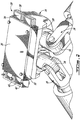
Fig. 2 is a partial perspective view of a damping unit according to one embodiment of the present invention, wherein the damping unit is mounted to a bearing block connected to an upper end of an actuator of the motion system ofFig. 1 ; -
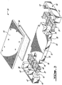
Fig. 3 is an exploded perspective view of the damping unit ofFig. 2 ; -
Fig. 4a is a plot illustrating measured vibrations in a motion simulator platform without any vibration damping units ofFig. 2 installed; -
Fig. 4b is a plot illustrating measured vibrations in a motion simulator platform with the damping units ofFig. 2 installed; and -
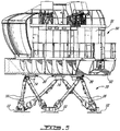
Fig. 5 is a schematic side elevation view of a motion simulator having a simulator cabin mounted on a motion platform which is displaceable by a motion system similar to that ofFig. 1 , the vibration damping units of the present invention being installed between the actuators of the motion system and the displaceable motion platform. - Referring now to
Fig.1 , amotion system 10 for a displaceable motion platform, such as that of a motion simulator, of the type commonly known as a Stewart platform is shown. Theplatform assembly 10 includes a base formed of threebase plates portions 12 fixed to an underlying support surface and therefore fixed relative to one another, six mobile and extensible legs oractuators 16 which have lower ends thereof engaged to thebase plate portions 12 and opposed upper ends engaged to at least threebearing block assemblies 14 which support the moving platform of the motion simulator cabin. Such amotion system 10 is used to displace amotion simulator 50, such as that depicted inFig. 5 , which generally includes asimulator cabin 51 mounted on adisplaceable motion platform 52. Themotion platform 52 is displaced and controlled bylinear actuators 16 such as those of themotion system 10. In the embodiment ofFig. 5 , thevibration damping units 30 of the present invention, which will be described in further detail below, are disposed between the upper ends of each of theactuators 16 and themotion platform 52, and more precisely between thebearing blocks 14, to which theactuators 16 are pivotably engaged, and themotion platform 52. - Each of the
actuators 16 is preferably a linear actuator and includes a firstuniversal joint 18 on one (lower) end and a seconduniversal joint 19 on the opposed (upper) end. The firstuniversal joint 18 is operably connected to one of thebase plate portions 12, and the seconduniversal joint 19 is connected to one of thebearing blocks 14. Each of the platform's sixlinear actuators 16 has two relatively telescoping parts, with a piston-like degree of freedom therebetween. The sixlinear actuators 16 with theuniversal joints bearing block assemblies 14 with six degrees of freedom, three rotational and three translational. Eachbase plate 12 has the lower ends of twoactuators 16 mounted thereto, each of these same two actuators being engaged at their upper ends todifferent bearing blocks 14. Thus, eachactuator 16 is connected to abearing block 14 along with a first adjacent actuator, and to a base portion along with a second adjacent actuator. Such a configuration allows the platform to move with respect to the base about six degrees of freedom. - The
actuators 16 are linear actuators, and more preferably electromechanical actuators. Although the present invention will be generally described with respect to its use with electromechanical linear actuators, it is to be understood that other suitable types of linear actuators, such as hydraulic actuators for example, can also be used. Each electromechanicallinear actuator 16 may be of a known type and as such includes a drive mechanism, which may include anelectric motor 20 having a rotatable output shaft (not shown), an outer tube orcylindrical member 22 surrounding a lead screw (not shown) connected to the output shaft, an extensible inner tube orcylindrical member 24 containing an internal nut (not shown) engaged with the lead screw such that turning of the screw by themotor 20 extends or retracts theinner tube 24 which acts as the outer extensible end of the actuator, and aposition feedback transducer 26 to determine the position of the innercylindrical member 24 with respect to the outercylindrical member 22. Such an actuator configuration is well known in the art and as such will not be described further herein. The electromechanical linear actuators depicted and described herein are but one type of such electrically-powered linear actuators which can be employed with the vibration damping unit of the present invention, and it is to be understood that other varieties of electromechanical linear actuators can be similarly used. For example, such alternate electrically-powered linear actuators could have side mounted motors, rather than the inline type depicted herein, or other drive mechanisms such as those which are belt and/or gear driven. While several advantages exist with all suchelectromechanical actuators 16, they generally generate more vibrations than comparative hydraulic actuators which particularly causes, among other things, undesirable audible noise. As such, additional damping of such vibrations is necessary for applications in which undue additional vibrations, particularly vibrations causing audible noise, are undesirable. - Referring to
Figs. 2-3 , the selectivevibration damping unit 30 is shown. Thedamping unit 30 is engaged with each of thebearing block 14, preferably being located between thebearing blocks 14 and the superimposed motion simulator platform supported thereby, in order to isolate the platform from unwanted vibrations produced by thelinear actuators 16. In the embodiment depicted, thevibration damping unit 30 is mounted to a flatupper surface 28 of each of thebearing blocks 14. Portions of the dampingunit 30, as will be described in further detail below, are in turn fastened to an underside of the motion platform. The dampingunit 30, when so installed, accordingly acts to damp unwanted vibrations which may originate in theactuator 16, in order to prevent them from passing, at least un-attenuated, upwards through the bearingblock 14 and into the motion platform. Therefore, each of the dampingunits 30 acts to vibrationally isolate the motion platform which is mounted to the bearing blocks 14 of the motion system. Thevibration damping unit 30 generally comprises at least a lower "floating" bearingplate 32,resilient members plate 32, and lateral mounting supports 42 retaining the assembly together and used to mount the damping unit to the motion platform. In the embodiment depicted, best seen inFig. 3 , an upper mountingplate 44 is also preferably provided above the upperresilient member 36. - In
Fig. 2 , the dampingunit 30 is shown mounted to theupper surface 28 of thebearing block 14, to which the upper ends of the two adjacentlinear actuators 16 are engaged via theuniversal joints 19. However, inFig. 2 the upper mountingplate 44 and one of the two opposed lateral mounting supports 42 have been removed for clarity. Theuniversal joints 19 at the upper ends of thelinear actuators 16 are mounted to thebearing block 14 as depicted in a cantilevered type manner, wherein the longitudinal axes of the linear actuators are offset relative to the center of thebearing block 14. This can provide certain spatial advantages, however can result in eccentric loads on thebearing block 14 and therefore on the dampingunit 30 mounted thereto. It is to be understood, however, that other, such as in-line (i.e. non-cantilevered type), bearing joint arrangements can similarly be used. - Referring now generally to
Fig. 3 , the bearingplate 32 is preferably made of aluminum and has aflat bottom surface 33 which abuts the correspondingflat surface 28 of thebearing block 14 and is similarly sized. The bearingplate 32 is rigidly fastened to thebearing block 14, such as via suitable threaded fasteners for example. Accordingly, any vibrations produced by thelinear actuator 16 or other vibration source interconnected, either directly or indirectly, to thebearing block 14 is transmitted directly through to the bearingplate 32 of the dampingunit 30. However, as noted above, this bearingplate 32 is said to be "floating", in that it is vibrationally isolated from the lateral mounting supports 42 and the upper mountingplate 44, which are fastened to the motion platform, by first and secondresilient members - The bearing
plate 32 preferably defines a rectangular shape, and includeslateral projections 34, or "wings", on opposed sides thereof. Theselateral projections 34 preferably include two projections protruding from each of two opposedlateral sides 35 of the bearingplate 32. Theselateral projections 34 are received within correspondingopenings 43, which are defined within the lateral mounting supports 42 and open upwards (i.e. towards the motion platform). However, the second, or lateral,resilient members 37 are first received within saidopenings 43, and are therefore located between thelateral projections 34 and the inner surfaces of theopenings 43 within the mounting supports 42. The lateralresilient members 37 includeside portions 38 andlower portions 40 which are adapted to abut all but an upper surface portion of thelateral projections 34, thereby completely separating thelateral projections 34 of the bearingplate 32 from the mounting supports 42. The lateralresilient members 37 therefore act as side and lower shock absorbers. Much as per the upperresilient member 36 described below, the laterresilient members 37 are preferably made of a resilient material such as an elastomer, rubber and/or a compound thereof. - Although in the depicted preferred embodiment the lateral
resilient members 37 disposed on opposed sides of the bearingplate 32 are each a one-piece unit, each preferably including two sets of side andlower portions 38,40 (one for each of the two lateral projections 34), it is to be understood that the side andlower portions 40 of each projection could be separate pieces of the resilient material, each inserted individually into theopenings 43 defined in the later mounting supports 42. - As the
openings 43 in the lateral mounting supports 42 have a closed lower surface, the lateral projections of the bearing plate which are received therein cannot drop out therefrom in a vertical direction, and once the two opposed lateral mounting supports 42 are fastened to the motion platform, the bearingplate 42 is securely retained thereby to provide a fail-safe assembly. Particularly, should any of the resilient material fail, thelateral projections 34 of the bearing plate would merely drop slightly within theopenings 43, however would be prevented from any further movement and retained in place by the rigidly fastened lateral mounting supports 42 which are fastened to the motion platform. - Overlaid on top of an
upper surface 31 of thelarge bearing plate 32 is provided the first, or upper,resilient member 36 which provides vibration damping in a vertical direction. This upperresilient member 36 is mat like, defining a much larger surface area than the second, or side/lower,resilient members 37, and overlying at least a portion of amajor surface 31 of the "floating" bearingplate 32. Accordingly, the relatively thin upperresilient member 36 is vertically disposed, or rather sandwiched, between the bearingplate 32 and the under surface of the mounting platform, or alternately of a flatupper mounting plate 44 rigidly fastened thereto. The upper mountingplate 44 is preferably made of steel. The upperresilient member 36 is preferably also made of an elastomer, a rubber and/or a compound thereof. - A plurality of
bolts 46 or other suitable fasteners are used to fasten the lateral mounting supports 42 to the motion platform. The upper mountingplate 44 is also fastened to the motion platform, and abuts the large upperresilient member 36 but is not fastened relatively thereto. Accordingly, only these two elements are rigidly fixed to the motion platform. The bearingplate 32 which is fixed to thebearing block 14 is therefore retained within the dampingunit 30 via theresilient members unit 30 which are rigidly connected to the motion platform. - As noted above, the lateral mounting supports 42 which retain the damping
unit 30 together are preferably fastened to the underside of the motion platform, or alternately to the upper mountingplate 44 which is itself fixed to the motion platform, by a plurality of threaded fasteners (for example bolts) 46 which are received within corresponding internally threadedholes 47 defined in the mounting supports 42. Accordingly, tightening thefasteners 46 applies pressure to compress at least the upperresilient member 36 between the floating bearingplate 32 and the motion platform and to compress thelower portions 40 of the lateralresilient members 37 between the mounting supports 42 and the bearingplate 32. This applies a compressive preload to at least these resilient members, thereby improving the resistance thereof to tensile forces. Such a compressive preloading is preferred, so as to at least limit, if not eliminate, the exposure of the resilient members to tensile forces. Such a preloading improves fatigue life of the selective dampingunit 30 as well as helps to prevent backlash on load reversal of the motion platform. While the amount of preload can be varied via the fastening means used to compress the resilient members prior to use of the damping unit, other characteristics can also be varied in order to control the amount and distribution of preload in the resilient members. For example, the offset bearing setup of thebearing block 14 depicted inFig. 2 can result in eccentric loading of the damping unit, and therefore the resilient members, thereabove. Accordingly, in one embodiment, the load on the resilient members, and particularly of the upperresilient member 36, can be normalized by having a non-uniform shape (for example, cross-sectional thickness) in order to maintain a relatively constant preload when such resilient members are exposed to non-uniform loading. Therefore, the physical characteristics of the resilient members can be predetermined and selected in order to counter-balance any non-uniform loading which may be expected in the damping unit due to the particular setup and characteristics of any given application. In at least one embodiment, for example, the upperresilient member 36 is provided with a gradually varying cross-sectional area such that one end thereof is thicker than an opposed end. Thus, a relatively constant preload of the resilient member is maintained when it is subjected to the expected non-uniform loading. - As mentioned above, some electromechanical
linear actuators 16 can produce significant vibrations, particularly along the axis of actuation (i.e. the longitudinal axis of the liner actuator), which is subsequently transmitted through to thebearing block 14. Without a suitable vibration damper/isolator as per the dampingunit 30, undesirable vibrations are transferred through to the motion platform and the simulator cabin thereon, causing audible noise and other unwanted vibrations within the simulator cabin. - The damping
unit 30 accordingly provides vibration damping in at least a first direction substantially perpendicular to the motion platform (and therefore to theupper surface 31 of theplate 32 of the damping unit) and at least a second direction substantially parallel to the motion platform (and therefore to theupper surface 31 of theplate 32 of the damping unit) which is normal to the first direction. Preferably, the dampingunit 30 provides selective damping in all three axes, namely two orthogonal axes defined in a common plane (such as one parallel to the upper surface 31) and a third axis normal to both of the two orthogonal directions (such as perpendicular to the upper surface 31). - The damping
unit 30 further preferably damps unwanted vibrations, such as those producing audible noise for example, which are transferred through to the motion platform from the linear actuators. Such audible noise is especially undesirable in the case of flight simulators used for professional training. On the other hand, it is nonetheless desirable to be able to transmit certain vibrations that are part of the input to the simulator cabin. The dampingunit 30 is therefore preferably "tuned" in order to allow for selective damping of certain vibration frequencies, such as high frequency noise-producing vibrations for example, while nevertheless transmitting other wanted vibration frequencies, such as low frequency input vibrations for example. In a preferred embodiment, the dampingunit 30 is tuned such as to at least significantly damp undesired high frequency vibrations above a predetermined high frequency threshold, while nevertheless transmitting most low frequency vibrations below a low frequency threshold. In one embodiment, described in further detail below, the high frequency threshold is about 150 Hz and the low frequency threshold is about 50 Hz. However, it is to be understood that other threshold values can be used, and will vary depending on the particular application, the type and number of linear actuators used, etc. The high and low frequency thresholds can also be the same value, such as to permit most vibrations below this value to be transmitted but most vibrations above this value to be damped, or vice versa depending on the given application and particular needs for the dampingunit 30. - Referring to
Figs. 4a and 4b , the illustrated plots depicts measured vibrations transmitted from the linear actuators to the motion platform of a motion simulator system. In both plots, the X axis represents time, and the Y axis represents amplitude of the vibrations.Fig. 4a is a plot of vibrations measured in a motion simulator platform without any vibration damping devices installed.Fig. 4b depicts a plot of vibrations measured in the same motion simulator platform having selective dampingunits 30 installed between each of the linear actuators and the platform. As clear fromFig. 4b , the vibration amplitudes transmitted from the linear actuators to the platform with the damping units installed therebetween are significantly less than those for the un-damped system (inFig. 4a ), being preferably reduced by at least a factor of 2.5 for average vibration levels and up to at least a factor of 5 for certain peak vibration levels. Preferably, above the high frequency threshold, vibration levels may be reduced by at least a factor of 10. - In use, a maximum frequency for the input vibrations that need to be transmitted is chosen; this will be the first frequency limit. Then, the frequencies of the undesirable vibrations in the motion simulator are measured to establish the minimum frequency for the vibrations that need to be dampened; this will be the second frequency limit. This is preferably done using a motion simulator having a "dead" cab, i.e. without any disturbing vibration sources within. A target natural frequency for the selective damping
unit 30 is then established considering these two frequency limits. The target natural frequency is preferably chosen such that it is situated between the first and second frequency limits, and is preferably, in at least one embodiment, about one half of the square of the second frequency limit. Then, the natural frequency of the selective damping unit is adjusted by varying the thickness and material characteristics of theresilient members resilient members 37 may be exposed to larger stresses for a given compressive force, therefore the material selected may have a different Young's modulus than that of the larger upperresilient member 36. Preferably, the lateralresilient members 37 have a Young's modulus higher than that of upperresilient member 36. - In one example, the first frequency limit was established at 50Hz, and the second frequency limit at 150Hz. A target natural frequency of the simulator was thus set at 70Hz. Suitable elastomer materials were chosen for each of the lateral
resilient members 37 and the upperresilient member 36, wherein the Young's modulus of the material of the lateralresilient members 37 is greater than that of the upperresilient member 37. In at least one embodiment, the Young's modulus of the lateralresilient members 37 is twice that of the upperresilient member 36. The thicknesses of the upperresilient member 36 and the lateralresilient members 37 were then varied, not necessarily uniformly, until the target natural frequency was reached, using computer simulations to establish the natural frequency for each thickness increment. The selective dampingunits 30 with a natural frequency of about 70Hz were then installed on a flight simulator. A beginning of frequency isolation of 100Hz was measured, with a 6dB attenuation around 200Hz. Thus, vibrations having a frequency above 150Hz were effectively dampened, while vibrations having a frequency lower than 50Hz were effectively transmitted. This is however but one example of the possible configurations of the vibration damping units of the present invention, suitable for one motion system using particular linear actuators. It is to be understood that as the vibrations produced by other electromechanical linear actuators will differ, the target natural frequency desired for the dampingunits 30 will vary given the particular application and equipped used. Accordingly, by appropriately selecting the characteristics of the resilient members, such as material type, stiffness, size, etc., the dampingunits 30 can be "tuned" as required to achieve a determined target natural frequency. While the first (lower) and second (upper) frequency limits can vary, at least the second frequency limit can do so considerably, in order to best correspond to the undesirable frequencies which the damping unit is to absorb (i.e. damp). The second frequency limit is at least equal to or greater than the first frequency limit. - The
vibration damping units 30 of the present invention provide several advantages, one of which being the fact that failure of theresilient members lateral support members 42 and the bearingplate 32, regardless of any shift of the bearing plate within the lateral supports due to failure of the resilient members therebetween. Thus, no additional control system is necessarily required to provide back up in case of failure of the resilient members. Further, the selective dampingunit 30 is generally less costly than most prior art damping units for motion simulators, which generally require complex assemblies. Moreover, the selective dampingunit 30 is cost and time effective to manufacture, having a limited number of components which further reduces the risk of malfunction and/or failure of the elements thereof. - The embodiments described above are intended to be exemplary. Those skilled in the art will therefore appreciate that the foregoing description is illustrative only, and that various alternatives and modifications can be devised.
- For example, the damping
unit 30 can easily be adapted to moving platforms other than six-degree of freedom simulator systems, such as amusement or entertainment systems for example, and can be driven by hydraulic, electromechanical or other types of actuators, or which are exposed to other sources of vibrations, such as in various types of vehicles, industrial equipment, etc. The dampingunit 30, while preferably being capable of selective damping of unwanted vibrations, can also be simply used to reduce all vibrations which would otherwise be transmitted from a source of vibrations to a moving platform connected thereto, such as to at least limit either audible or physical vibrations in the platform. In addition thereto, silent-block type resilient inserts can be provided within the output pins of theuniversal joints 19 within the bearing blocks 14. - Accordingly, the present invention is intended to embrace all such alternatives, modifications and variances which fall within the scope of the appended claims.
Claims (19)
- A damping unit (30) for an actuated motion platform (52), the damping unit including:a plate (32) having a top surface (31), a bottom surface (33) and opposed lateral plate surfaces (35), the bottom surface being adapted to be rigidly connected to a vibration source, the opposed lateral plate surfaces (35) being disposed between the top surface (31) and the bottom surface (33), the lateral plate surfaces (35) including lateral projections (34), the lateral projections (34) each having a top surface, a bottom surface, and at least three lateral surfaces;lateral mounting supports (42) each receiving at least one of said lateral projections (34) and being adapted for rigid fastening to the motion platform (52);a first resilient member (36) overlying at least a portion of said top surface (31) of said plate (32) and being retained between the top surface (31) and the motion platform (52) by said lateral mounting supports (42), said first resilient member (36) providing vibration absorption such as to limit vibrations transmitted from said plate (32) to said motion platform (52) in at least a direction substantially perpendicular to said top surface (31);two second resilient members (37), each of the two second resilient members (37) being disposed between the at least three lateral surfaces of a corresponding one of the lateral projections (34) and a corresponding one of the lateral mounting supports (42), such that the lateral mounting supports (42) constrain the second resilient members (37) in at least a first direction substantially parallel to the top surface (31) and a second direction substantially parallel to the top surface (31), the second direction being substantially perpendicular to the first direction, said second resilient members (37) providing vibration absorption such as to limit vibrations transmitted from said plate (32) to said motion platform (52) in at least a direction substantially parallel to said top surface (31); andwherein thicknesses and material characteristics of the first resilient member (36) and of the two second resilient members (37) provide for dampening at least a selected frequency range of vibrations generated by the vibration source thereby limiting unwanted vibrations which are transmitted to the motion platform (52).
- The damping unit according to claim 1, wherein the selected range of vibrations are those having a frequency at least higher than a predetermined second limit.
- The damping unit according to claim 2, wherein vibrations generated by the vibration source having a frequency at least higher than said second limit are damped by the damping unit and vibrations generated by the vibration source having a frequency at least lower than a first limit are transmitted through the damping unit, such as to damp said selected range of vibrations at least above said second limit.
- The damping unit according to claim 2 or 3, wherein said second limit is at least about 100 Hz.
- The damping unit according to claim 4, wherein said second limit is about 150 Hz.
- The damping unit according to claim 3, wherein said first limit is about 50 Hz.
- The damping unit according to claim 1, wherein the vibration source is a linear actuator (16) moveably connecting the platform to a fixed base (12).
- The damping unit according to claim 7, wherein the linear actuator is an electromechanical linear actuator.
- The damping unit according to claim 1, further comprising an upper mounting plate (44) fastenable to said platform, said upper mounting plate overlying said first resilient member and being disposed between said platform and said first resilient member.
- The damping unit according to claim 1, wherein said second resilient members and said lateral mounting supports are configured to receive the lateral projections in openings (43) defined therein.
- The damping unit according to claim 10, wherein said openings are closed-bottom, such that the plate is held captive within said lateral mounting supports.
- The damping unit according to claim 1, wherein said first and second directions substantially parallel to the top surface and said direction substantially perpendicular to said top surface define three axes perpendicular to each other.
- The damping unit according to claim 1, wherein at least said first resilient member is preloaded.
- The damping unit according to claim 13, wherein the preload is provided by compression between said plate and the platform by said lateral mounting supports.
- A multiple degree-of-freedom motion simulator assembly (50) comprising:a fixed base (12);a displaceable simulator platform (52);a plurality of extensible and retractable linear actuators (16) having upper ends thereof interconnected with the platform and lower ends thereof interconnected with the fixed base, the linear actuators being operable to displace the simulator platform in said multiple-degrees-of-freedom relative to said fixed base; characterised in that a damping unit (30) of any one of claims 1 to 14 disposed between at least one of each of said upper ends and the platform, wherein the plate of said damping unit (30) is engaged to at least one said upper end and wherein said vibration source is at least one of said plurality of extensible and retractable linear actuators (16).
- The assembly according to claim 15, wherein said damping units are mounted between said upper ends of said linear actuators and said platform.
- The assembly according to claim 16, wherein each one of the plurality of linear actuators is an electromechanical actuator.
- An electromechanical linear actuator (16) for a motion simulator system (10) having a motion platform (52) displaceable in multiple degrees-of-freedom relative to a fixed base (12) by at least one said actuator, the electromechanical linear actuator comprising:first and second telescoping cylindrical members (22, 24) defining a common longitudinal axis, a lower end of said first cylindrical member having a first joint (18) adapted for engagement with said fixed base and an upper end of said second cylindrical member having a second joint (19) adapted for engagement with said motion platform;a drive mechanism (20) operable to extend and retract said first and second cylindrical member relative to each other to displace the motion platform relative to said fixed base; and characterised in that a damping unit (30) according to any one of claims 1 to 14 engaged with said upper end, said first resilient member of said damping unit (30) being disposed between said upper end and said motion platform, wherein said electromechanical linear actuator provides said vibration source.
- The electromechanical linear actuator according to claim 18, wherein said selected frequency range corresponds to audible vibrations produced in said platform from vibrations generated by said linear actuator.
Applications Claiming Priority (1)
| Application Number | Priority Date | Filing Date | Title |
|---|---|---|---|
| US11/203,122 US7806697B2 (en) | 2005-08-15 | 2005-08-15 | Method and apparatus for damping vibrations in a motion simulation platform |
Publications (3)
| Publication Number | Publication Date |
|---|---|
| EP1755095A2 EP1755095A2 (en) | 2007-02-21 |
| EP1755095A3 EP1755095A3 (en) | 2010-06-02 |
| EP1755095B1 true EP1755095B1 (en) | 2018-02-28 |
Family
ID=37499711
Family Applications (1)
| Application Number | Title | Priority Date | Filing Date |
|---|---|---|---|
| EP06254240.2A Active EP1755095B1 (en) | 2005-08-15 | 2006-08-11 | Method and apparatus for damping vibrations in a motion simulation platform |
Country Status (3)
| Country | Link |
|---|---|
| US (1) | US7806697B2 (en) |
| EP (1) | EP1755095B1 (en) |
| CA (1) | CA2556006C (en) |
Families Citing this family (23)
| Publication number | Priority date | Publication date | Assignee | Title |
|---|---|---|---|---|
| US8454366B2 (en) * | 2005-11-30 | 2013-06-04 | D-Box Technologies Inc. | Actuated support platform for video system |
| JP2011502847A (en) * | 2007-11-07 | 2011-01-27 | ヘリスカンディア アンパーツゼルスカブ | Autonomous rotor system for aircraft |
| EP2325522B1 (en) * | 2009-11-20 | 2013-01-02 | EADS Deutschland GmbH | Shock-isolation structure |
| ES2363549B1 (en) * | 2011-03-08 | 2012-03-23 | Instituto Tecnológico Del Embalaje, Transporte Y Log�?Stica | MACHINE MOVEMENT SIMULATOR PRODUCED DURING TRANSPORTATION |
| US9004921B2 (en) * | 2011-05-26 | 2015-04-14 | Industrial Smoke & Mirrors, Inc. | Motion and vibration cuing system |
| NL2009805C2 (en) * | 2012-11-14 | 2014-05-15 | E2M Technologies B V | A 6 degree-of-freedom motion simulator assembly. |
| US9242181B2 (en) | 2012-12-03 | 2016-01-26 | Dynamic Motion Group Gmbh | Amusement park elevator drop ride system and associated methods |
| US9259657B2 (en) | 2012-12-03 | 2016-02-16 | Dynamic Motion Group Gmbh | Motion simulation system and associated methods |
| US9536446B2 (en) * | 2012-12-03 | 2017-01-03 | Dynamic Motion Group Gmbh | Motion simulation system controller and associated methods |
| US9446835B2 (en) | 2013-01-16 | 2016-09-20 | Otto Aviation Group | Aircraft wing |
| US9090324B2 (en) | 2013-01-16 | 2015-07-28 | Ottoa Aviation Group | Aircraft support structure |
| US9669939B2 (en) | 2013-01-16 | 2017-06-06 | Otto Aviation Group | Aircraft supplemental thrust device and method of operating the same |
| DK2973500T3 (en) * | 2013-03-15 | 2020-01-06 | Oceaneering Int Inc | MOVING PLATFORM CONFIGURATION |
| US9836988B2 (en) * | 2015-06-10 | 2017-12-05 | Robert R. Harrison | Emergency medical services and paramedic simulation and training apparatus in a transferable environment |
| KR102723693B1 (en) * | 2016-01-15 | 2024-10-31 | 고쿠사이 게이소쿠키 가부시키가이샤 | Vibration application device, and electrodynamic actuator |
| CN105702117A (en) * | 2016-04-29 | 2016-06-22 | 燕山大学 | Six-axis-driven three-degree-of-freedom static load balancing large parallel movement simulation platform |
| US12167796B2 (en) * | 2016-05-04 | 2024-12-17 | Aaron DeJule | Human support structure |
| RU167789U1 (en) * | 2016-05-30 | 2017-01-10 | Акционерное общество "Тренажерные Системы" | SIX-DYNAMIC DYNAMIC PLATFORM |
| FR3067155B1 (en) * | 2017-06-01 | 2022-01-28 | Thales Sa | DEVICE FOR SAFETY OF ELECTRICAL MOVEMENTS OF MOBILE PLATFORMS FOR SIMULATORS |
| CN110867128A (en) * | 2018-08-28 | 2020-03-06 | 上海科赫商务咨询有限公司 | Suspension damping change simulator and application thereof |
| CN110874966A (en) * | 2018-09-03 | 2020-03-10 | 海口未来技术研究院 | Control method and device of motion simulator, storage medium and processor |
| US11579161B2 (en) * | 2019-04-16 | 2023-02-14 | Robotiques Haply Inc. | Orientation preserved damping for object tracking subjected to haptic stimulus |
| WO2020228992A1 (en) * | 2019-05-15 | 2020-11-19 | Dynisma Ltd. | Motion generator |
Family Cites Families (20)
| Publication number | Priority date | Publication date | Assignee | Title |
|---|---|---|---|---|
| DE1249600B (en) * | 1962-12-03 | |||
| USRE27051E (en) * | 1967-11-28 | 1971-02-09 | Motion simulator | |
| US3577659A (en) * | 1969-08-06 | 1971-05-04 | Singer General Precision | Motion simulator actuator joint |
| US3967387A (en) * | 1974-10-21 | 1976-07-06 | Daniel Marchegiani | Motion simulator |
| US3984924A (en) * | 1975-06-23 | 1976-10-12 | The Singer Company | Vibratory simulator motion system |
| JPS5690725A (en) * | 1979-12-20 | 1981-07-23 | Nissan Motor Co Ltd | Mounting device for engine |
| JPS60146931A (en) | 1984-01-09 | 1985-08-02 | Mitsubishi Heavy Ind Ltd | Vibro-isolator |
| GB2179605B (en) * | 1985-08-27 | 1988-11-16 | Singer Link Miles Ltd | Motion simulator |
| US5605462A (en) * | 1991-07-12 | 1997-02-25 | Denne Developments Ltd. | Motion imparting apparatus |
| US5366375A (en) * | 1992-05-11 | 1994-11-22 | Sarnicola John F | Motion simulator |
| US5931739A (en) * | 1993-12-27 | 1999-08-03 | Moog Inc. | Fail-safe ride simulator |
| US5853330A (en) * | 1994-06-02 | 1998-12-29 | Engstrand; Brad | Sensory simulator and editor |
| US5551661A (en) * | 1994-10-11 | 1996-09-03 | Bunker; Donald D. | Automotive transmission mount |
| US6022005A (en) * | 1996-09-27 | 2000-02-08 | Trw Inc. | Semi-active vibration isolator and fine positioning mount |
| US5971375A (en) * | 1996-11-26 | 1999-10-26 | Trw Inc. | Isolator apparatus for multi-dimensional vibrational disturbances |
| FR2757925B1 (en) * | 1996-12-27 | 1999-03-26 | Thomson Csf | MODULAR DEVICE FOR MOVING LOAD ACCORDING TO AT LEAST THREE DEGREES OF FREEDOM |
| US6634885B2 (en) * | 2000-01-20 | 2003-10-21 | Fidelity Flight Simulation, Inc. | Flight simulators |
| US6315094B1 (en) * | 2000-05-19 | 2001-11-13 | The United States Of America As Represented By The Secretary Of The Air Force | Passive virtual skyhook vibration isolation system |
| US6676116B2 (en) * | 2001-07-05 | 2004-01-13 | The Boeing Company | Elastomeric suspension and mounting system |
| US20030168295A1 (en) * | 2002-02-12 | 2003-09-11 | Zhixiu Han | Active vibration isolation system |
-
2005
- 2005-08-15 US US11/203,122 patent/US7806697B2/en active Active
-
2006
- 2006-08-10 CA CA2556006A patent/CA2556006C/en active Active
- 2006-08-11 EP EP06254240.2A patent/EP1755095B1/en active Active
Non-Patent Citations (1)
| Title |
|---|
| None * |
Also Published As
| Publication number | Publication date |
|---|---|
| US7806697B2 (en) | 2010-10-05 |
| EP1755095A2 (en) | 2007-02-21 |
| US20070059668A1 (en) | 2007-03-15 |
| CA2556006A1 (en) | 2007-02-15 |
| CA2556006C (en) | 2013-10-22 |
| EP1755095A3 (en) | 2010-06-02 |
Similar Documents
| Publication | Publication Date | Title |
|---|---|---|
| US7806697B2 (en) | Method and apparatus for damping vibrations in a motion simulation platform | |
| US5178357A (en) | Vibration isolation system | |
| US5370352A (en) | Damped vibration isolation system | |
| US11624420B1 (en) | Isolation system and method | |
| EP1543253A2 (en) | Piezoelectric liquid inertia vibration eliminator | |
| KR20150107740A (en) | Simulator | |
| KR102444015B1 (en) | Anti-vibration electrical safety control panel | |
| KR101634184B1 (en) | Helicopter | |
| KR100829489B1 (en) | Modular Tuned Mass Attenuator | |
| US7267010B2 (en) | Inertial mass guided single axis vibration test machine | |
| EP3899314B1 (en) | Coaxial spring damper device and system | |
| KR101524855B1 (en) | Cylindrical vibration control device having high-damping rubber | |
| Khorrami et al. | Three-degree-of-freedom adaptive-passive isolator for launch vehicle payloads | |
| EP0737279A1 (en) | Vibration isolation system | |
| US10774898B2 (en) | Compact vibration reducing human support | |
| JPH0439440A (en) | Vibration isolating device | |
| JP2002276194A (en) | Seismic isolation device | |
| US20020109277A1 (en) | Shock and vibration absorption system | |
| DE102004013966B4 (en) | Active element for vibration reduction of components, in particular for aircraft components | |
| CN224260800U (en) | Vibration isolators, vibration isolation bases and air conditioning units | |
| CA3123627C (en) | Coaxial spring damper device and system | |
| JP2025109414A (en) | Vibration isolation unit and vibration isolation support device | |
| CN119802121A (en) | A multi-degree-of-freedom dynamic vibration absorber and adjustment method | |
| CN118274054A (en) | Shock absorber and vibration reduction assembly | |
| JP2006266387A (en) | Vibration isolator |
Legal Events
| Date | Code | Title | Description |
|---|---|---|---|
| PUAI | Public reference made under article 153(3) epc to a published international application that has entered the european phase |
Free format text: ORIGINAL CODE: 0009012 |
|
| AK | Designated contracting states |
Kind code of ref document: A2 Designated state(s): AT BE BG CH CY CZ DE DK EE ES FI FR GB GR HU IE IS IT LI LT LU LV MC NL PL PT RO SE SI SK TR |
|
| AX | Request for extension of the european patent |
Extension state: AL BA HR MK YU |
|
| PUAL | Search report despatched |
Free format text: ORIGINAL CODE: 0009013 |
|
| AK | Designated contracting states |
Kind code of ref document: A3 Designated state(s): AT BE BG CH CY CZ DE DK EE ES FI FR GB GR HU IE IS IT LI LT LU LV MC NL PL PT RO SE SI SK TR |
|
| AX | Request for extension of the european patent |
Extension state: AL BA HR MK RS |
|
| 17P | Request for examination filed |
Effective date: 20101129 |
|
| AKX | Designation fees paid |
Designated state(s): AT BE BG CH CY CZ DE DK EE ES FI FR GB GR HU IE IS IT LI LT LU LV MC NL PL PT RO SE SI SK TR |
|
| 17Q | First examination report despatched |
Effective date: 20140204 |
|
| RIC1 | Information provided on ipc code assigned before grant |
Ipc: G09B 9/02 20060101ALN20170418BHEP Ipc: G09B 9/00 20060101AFI20170418BHEP Ipc: G09B 9/12 20060101ALI20170418BHEP |
|
| RIC1 | Information provided on ipc code assigned before grant |
Ipc: G09B 9/00 20060101AFI20170516BHEP Ipc: G09B 9/02 20060101ALN20170516BHEP Ipc: G09B 9/12 20060101ALI20170516BHEP |
|
| RIC1 | Information provided on ipc code assigned before grant |
Ipc: G09B 9/02 20060101ALN20170619BHEP Ipc: G09B 9/12 20060101ALI20170619BHEP Ipc: G09B 9/00 20060101AFI20170619BHEP |
|
| RIC1 | Information provided on ipc code assigned before grant |
Ipc: G09B 9/02 20060101ALN20170711BHEP Ipc: G09B 9/00 20060101AFI20170711BHEP Ipc: G09B 9/12 20060101ALI20170711BHEP |
|
| GRAP | Despatch of communication of intention to grant a patent |
Free format text: ORIGINAL CODE: EPIDOSNIGR1 |
|
| STAA | Information on the status of an ep patent application or granted ep patent |
Free format text: STATUS: GRANT OF PATENT IS INTENDED |
|
| INTG | Intention to grant announced |
Effective date: 20170922 |
|
| GRAS | Grant fee paid |
Free format text: ORIGINAL CODE: EPIDOSNIGR3 |
|
| GRAA | (expected) grant |
Free format text: ORIGINAL CODE: 0009210 |
|
| STAA | Information on the status of an ep patent application or granted ep patent |
Free format text: STATUS: THE PATENT HAS BEEN GRANTED |
|
| AK | Designated contracting states |
Kind code of ref document: B1 Designated state(s): AT BE BG CH CY CZ DE DK EE ES FI FR GB GR HU IE IS IT LI LT LU LV MC NL PL PT RO SE SI SK TR |
|
| REG | Reference to a national code |
Ref country code: GB Ref legal event code: FG4D Ref country code: CH Ref legal event code: EP |
|
| REG | Reference to a national code |
Ref country code: AT Ref legal event code: REF Ref document number: 974944 Country of ref document: AT Kind code of ref document: T Effective date: 20180315 |
|
| REG | Reference to a national code |
Ref country code: IE Ref legal event code: FG4D |
|
| REG | Reference to a national code |
Ref country code: DE Ref legal event code: R096 Ref document number: 602006054799 Country of ref document: DE |
|
| REG | Reference to a national code |
Ref country code: NL Ref legal event code: FP |
|
| REG | Reference to a national code |
Ref country code: LT Ref legal event code: MG4D |
|
| REG | Reference to a national code |
Ref country code: AT Ref legal event code: MK05 Ref document number: 974944 Country of ref document: AT Kind code of ref document: T Effective date: 20180228 |
|
| PG25 | Lapsed in a contracting state [announced via postgrant information from national office to epo] |
Ref country code: FI Free format text: LAPSE BECAUSE OF FAILURE TO SUBMIT A TRANSLATION OF THE DESCRIPTION OR TO PAY THE FEE WITHIN THE PRESCRIBED TIME-LIMIT Effective date: 20180228 Ref country code: CY Free format text: LAPSE BECAUSE OF FAILURE TO SUBMIT A TRANSLATION OF THE DESCRIPTION OR TO PAY THE FEE WITHIN THE PRESCRIBED TIME-LIMIT Effective date: 20180228 Ref country code: ES Free format text: LAPSE BECAUSE OF FAILURE TO SUBMIT A TRANSLATION OF THE DESCRIPTION OR TO PAY THE FEE WITHIN THE PRESCRIBED TIME-LIMIT Effective date: 20180228 Ref country code: LT Free format text: LAPSE BECAUSE OF FAILURE TO SUBMIT A TRANSLATION OF THE DESCRIPTION OR TO PAY THE FEE WITHIN THE PRESCRIBED TIME-LIMIT Effective date: 20180228 |
|
| PG25 | Lapsed in a contracting state [announced via postgrant information from national office to epo] |
Ref country code: BG Free format text: LAPSE BECAUSE OF FAILURE TO SUBMIT A TRANSLATION OF THE DESCRIPTION OR TO PAY THE FEE WITHIN THE PRESCRIBED TIME-LIMIT Effective date: 20180528 Ref country code: AT Free format text: LAPSE BECAUSE OF FAILURE TO SUBMIT A TRANSLATION OF THE DESCRIPTION OR TO PAY THE FEE WITHIN THE PRESCRIBED TIME-LIMIT Effective date: 20180228 Ref country code: SE Free format text: LAPSE BECAUSE OF FAILURE TO SUBMIT A TRANSLATION OF THE DESCRIPTION OR TO PAY THE FEE WITHIN THE PRESCRIBED TIME-LIMIT Effective date: 20180228 Ref country code: LV Free format text: LAPSE BECAUSE OF FAILURE TO SUBMIT A TRANSLATION OF THE DESCRIPTION OR TO PAY THE FEE WITHIN THE PRESCRIBED TIME-LIMIT Effective date: 20180228 Ref country code: GR Free format text: LAPSE BECAUSE OF FAILURE TO SUBMIT A TRANSLATION OF THE DESCRIPTION OR TO PAY THE FEE WITHIN THE PRESCRIBED TIME-LIMIT Effective date: 20180529 |
|
| PG25 | Lapsed in a contracting state [announced via postgrant information from national office to epo] |
Ref country code: IT Free format text: LAPSE BECAUSE OF FAILURE TO SUBMIT A TRANSLATION OF THE DESCRIPTION OR TO PAY THE FEE WITHIN THE PRESCRIBED TIME-LIMIT Effective date: 20180228 Ref country code: RO Free format text: LAPSE BECAUSE OF FAILURE TO SUBMIT A TRANSLATION OF THE DESCRIPTION OR TO PAY THE FEE WITHIN THE PRESCRIBED TIME-LIMIT Effective date: 20180228 Ref country code: PL Free format text: LAPSE BECAUSE OF FAILURE TO SUBMIT A TRANSLATION OF THE DESCRIPTION OR TO PAY THE FEE WITHIN THE PRESCRIBED TIME-LIMIT Effective date: 20180228 Ref country code: EE Free format text: LAPSE BECAUSE OF FAILURE TO SUBMIT A TRANSLATION OF THE DESCRIPTION OR TO PAY THE FEE WITHIN THE PRESCRIBED TIME-LIMIT Effective date: 20180228 |
|
| REG | Reference to a national code |
Ref country code: DE Ref legal event code: R097 Ref document number: 602006054799 Country of ref document: DE |
|
| PG25 | Lapsed in a contracting state [announced via postgrant information from national office to epo] |
Ref country code: SK Free format text: LAPSE BECAUSE OF FAILURE TO SUBMIT A TRANSLATION OF THE DESCRIPTION OR TO PAY THE FEE WITHIN THE PRESCRIBED TIME-LIMIT Effective date: 20180228 Ref country code: DK Free format text: LAPSE BECAUSE OF FAILURE TO SUBMIT A TRANSLATION OF THE DESCRIPTION OR TO PAY THE FEE WITHIN THE PRESCRIBED TIME-LIMIT Effective date: 20180228 Ref country code: CZ Free format text: LAPSE BECAUSE OF FAILURE TO SUBMIT A TRANSLATION OF THE DESCRIPTION OR TO PAY THE FEE WITHIN THE PRESCRIBED TIME-LIMIT Effective date: 20180228 |
|
| PLBE | No opposition filed within time limit |
Free format text: ORIGINAL CODE: 0009261 |
|
| STAA | Information on the status of an ep patent application or granted ep patent |
Free format text: STATUS: NO OPPOSITION FILED WITHIN TIME LIMIT |
|
| 26N | No opposition filed |
Effective date: 20181129 |
|
| PG25 | Lapsed in a contracting state [announced via postgrant information from national office to epo] |
Ref country code: SI Free format text: LAPSE BECAUSE OF FAILURE TO SUBMIT A TRANSLATION OF THE DESCRIPTION OR TO PAY THE FEE WITHIN THE PRESCRIBED TIME-LIMIT Effective date: 20180228 |
|
| PG25 | Lapsed in a contracting state [announced via postgrant information from national office to epo] |
Ref country code: MC Free format text: LAPSE BECAUSE OF FAILURE TO SUBMIT A TRANSLATION OF THE DESCRIPTION OR TO PAY THE FEE WITHIN THE PRESCRIBED TIME-LIMIT Effective date: 20180228 |
|
| REG | Reference to a national code |
Ref country code: CH Ref legal event code: PL |
|
| PG25 | Lapsed in a contracting state [announced via postgrant information from national office to epo] |
Ref country code: LI Free format text: LAPSE BECAUSE OF NON-PAYMENT OF DUE FEES Effective date: 20180831 Ref country code: LU Free format text: LAPSE BECAUSE OF NON-PAYMENT OF DUE FEES Effective date: 20180811 Ref country code: CH Free format text: LAPSE BECAUSE OF NON-PAYMENT OF DUE FEES Effective date: 20180831 |
|
| REG | Reference to a national code |
Ref country code: BE Ref legal event code: MM Effective date: 20180831 |
|
| REG | Reference to a national code |
Ref country code: IE Ref legal event code: MM4A |
|
| PG25 | Lapsed in a contracting state [announced via postgrant information from national office to epo] |
Ref country code: IE Free format text: LAPSE BECAUSE OF NON-PAYMENT OF DUE FEES Effective date: 20180811 |
|
| PG25 | Lapsed in a contracting state [announced via postgrant information from national office to epo] |
Ref country code: FR Free format text: LAPSE BECAUSE OF NON-PAYMENT OF DUE FEES Effective date: 20180831 Ref country code: BE Free format text: LAPSE BECAUSE OF NON-PAYMENT OF DUE FEES Effective date: 20180831 |
|
| PG25 | Lapsed in a contracting state [announced via postgrant information from national office to epo] |
Ref country code: TR Free format text: LAPSE BECAUSE OF FAILURE TO SUBMIT A TRANSLATION OF THE DESCRIPTION OR TO PAY THE FEE WITHIN THE PRESCRIBED TIME-LIMIT Effective date: 20180228 |
|
| PG25 | Lapsed in a contracting state [announced via postgrant information from national office to epo] |
Ref country code: HU Free format text: LAPSE BECAUSE OF FAILURE TO SUBMIT A TRANSLATION OF THE DESCRIPTION OR TO PAY THE FEE WITHIN THE PRESCRIBED TIME-LIMIT; INVALID AB INITIO Effective date: 20060811 Ref country code: PT Free format text: LAPSE BECAUSE OF FAILURE TO SUBMIT A TRANSLATION OF THE DESCRIPTION OR TO PAY THE FEE WITHIN THE PRESCRIBED TIME-LIMIT Effective date: 20180228 |
|
| PG25 | Lapsed in a contracting state [announced via postgrant information from national office to epo] |
Ref country code: IS Free format text: LAPSE BECAUSE OF FAILURE TO SUBMIT A TRANSLATION OF THE DESCRIPTION OR TO PAY THE FEE WITHIN THE PRESCRIBED TIME-LIMIT Effective date: 20180628 |
|
| PGFP | Annual fee paid to national office [announced via postgrant information from national office to epo] |
Ref country code: NL Payment date: 20250821 Year of fee payment: 20 |
|
| PGFP | Annual fee paid to national office [announced via postgrant information from national office to epo] |
Ref country code: DE Payment date: 20250819 Year of fee payment: 20 |
|
| PGFP | Annual fee paid to national office [announced via postgrant information from national office to epo] |
Ref country code: GB Payment date: 20250822 Year of fee payment: 20 |