EP1754292B1 - Wavelength stabilized laser module - Google Patents
Wavelength stabilized laser module Download PDFInfo
- Publication number
- EP1754292B1 EP1754292B1 EP04736612A EP04736612A EP1754292B1 EP 1754292 B1 EP1754292 B1 EP 1754292B1 EP 04736612 A EP04736612 A EP 04736612A EP 04736612 A EP04736612 A EP 04736612A EP 1754292 B1 EP1754292 B1 EP 1754292B1
- Authority
- EP
- European Patent Office
- Prior art keywords
- laser
- wavelength
- light
- sensor
- signal
- Prior art date
- Legal status (The legal status is an assumption and is not a legal conclusion. Google has not performed a legal analysis and makes no representation as to the accuracy of the status listed.)
- Expired - Lifetime
Links
- 230000005540 biological transmission Effects 0.000 claims abstract description 31
- 238000012544 monitoring process Methods 0.000 claims abstract description 17
- 230000004044 response Effects 0.000 claims abstract description 17
- 239000004065 semiconductor Substances 0.000 claims abstract description 9
- 238000001816 cooling Methods 0.000 claims abstract description 7
- 238000001228 spectrum Methods 0.000 claims abstract description 3
- 239000002131 composite material Substances 0.000 claims description 9
- 230000004907 flux Effects 0.000 claims description 5
- 238000010586 diagram Methods 0.000 description 37
- BJQHLKABXJIVAM-UHFFFAOYSA-N bis(2-ethylhexyl) phthalate Chemical compound CCCCC(CC)COC(=O)C1=CC=CC=C1C(=O)OCC(CC)CCCC BJQHLKABXJIVAM-UHFFFAOYSA-N 0.000 description 22
- 230000003287 optical effect Effects 0.000 description 8
- 238000005259 measurement Methods 0.000 description 7
- 230000035945 sensitivity Effects 0.000 description 6
- 238000000926 separation method Methods 0.000 description 5
- 239000007787 solid Substances 0.000 description 4
- 230000008901 benefit Effects 0.000 description 3
- 230000007246 mechanism Effects 0.000 description 3
- 239000013307 optical fiber Substances 0.000 description 3
- 238000004088 simulation Methods 0.000 description 3
- 230000006641 stabilisation Effects 0.000 description 3
- 238000011105 stabilization Methods 0.000 description 3
- 230000008859 change Effects 0.000 description 2
- 150000001875 compounds Chemical group 0.000 description 2
- 238000006073 displacement reaction Methods 0.000 description 2
- 238000002310 reflectometry Methods 0.000 description 2
- 230000003595 spectral effect Effects 0.000 description 2
- 229910052729 chemical element Inorganic materials 0.000 description 1
- 230000007423 decrease Effects 0.000 description 1
- 230000000593 degrading effect Effects 0.000 description 1
- 230000001419 dependent effect Effects 0.000 description 1
- 230000002349 favourable effect Effects 0.000 description 1
- 239000000835 fiber Substances 0.000 description 1
- 238000004519 manufacturing process Methods 0.000 description 1
- 239000000463 material Substances 0.000 description 1
- 230000000737 periodic effect Effects 0.000 description 1
- 230000009467 reduction Effects 0.000 description 1
- 230000000087 stabilizing effect Effects 0.000 description 1
Images





Classifications
-
- H—ELECTRICITY
- H01—ELECTRIC ELEMENTS
- H01S—DEVICES USING THE PROCESS OF LIGHT AMPLIFICATION BY STIMULATED EMISSION OF RADIATION [LASER] TO AMPLIFY OR GENERATE LIGHT; DEVICES USING STIMULATED EMISSION OF ELECTROMAGNETIC RADIATION IN WAVE RANGES OTHER THAN OPTICAL
- H01S5/00—Semiconductor lasers
- H01S5/02—Structural details or components not essential to laser action
- H01S5/024—Arrangements for thermal management
- H01S5/02407—Active cooling, e.g. the laser temperature is controlled by a thermo-electric cooler or water cooling
- H01S5/02415—Active cooling, e.g. the laser temperature is controlled by a thermo-electric cooler or water cooling by using a thermo-electric cooler [TEC], e.g. Peltier element
-
- H—ELECTRICITY
- H01—ELECTRIC ELEMENTS
- H01S—DEVICES USING THE PROCESS OF LIGHT AMPLIFICATION BY STIMULATED EMISSION OF RADIATION [LASER] TO AMPLIFY OR GENERATE LIGHT; DEVICES USING STIMULATED EMISSION OF ELECTROMAGNETIC RADIATION IN WAVE RANGES OTHER THAN OPTICAL
- H01S5/00—Semiconductor lasers
- H01S5/06—Arrangements for controlling the laser output parameters, e.g. by operating on the active medium
- H01S5/068—Stabilisation of laser output parameters
- H01S5/0683—Stabilisation of laser output parameters by monitoring the optical output parameters
-
- H—ELECTRICITY
- H01—ELECTRIC ELEMENTS
- H01S—DEVICES USING THE PROCESS OF LIGHT AMPLIFICATION BY STIMULATED EMISSION OF RADIATION [LASER] TO AMPLIFY OR GENERATE LIGHT; DEVICES USING STIMULATED EMISSION OF ELECTROMAGNETIC RADIATION IN WAVE RANGES OTHER THAN OPTICAL
- H01S5/00—Semiconductor lasers
- H01S5/06—Arrangements for controlling the laser output parameters, e.g. by operating on the active medium
- H01S5/068—Stabilisation of laser output parameters
- H01S5/0683—Stabilisation of laser output parameters by monitoring the optical output parameters
- H01S5/0687—Stabilising the frequency of the laser
-
- H—ELECTRICITY
- H04—ELECTRIC COMMUNICATION TECHNIQUE
- H04B—TRANSMISSION
- H04B10/00—Transmission systems employing electromagnetic waves other than radio-waves, e.g. infrared, visible or ultraviolet light, or employing corpuscular radiation, e.g. quantum communication
- H04B10/50—Transmitters
- H04B10/572—Wavelength control
-
- H—ELECTRICITY
- H01—ELECTRIC ELEMENTS
- H01S—DEVICES USING THE PROCESS OF LIGHT AMPLIFICATION BY STIMULATED EMISSION OF RADIATION [LASER] TO AMPLIFY OR GENERATE LIGHT; DEVICES USING STIMULATED EMISSION OF ELECTROMAGNETIC RADIATION IN WAVE RANGES OTHER THAN OPTICAL
- H01S5/00—Semiconductor lasers
- H01S5/06—Arrangements for controlling the laser output parameters, e.g. by operating on the active medium
- H01S5/068—Stabilisation of laser output parameters
- H01S5/06804—Stabilisation of laser output parameters by monitoring an external parameter, e.g. temperature
Definitions
- the present invention relates generally to the production of laser signals which are suitable for wavelength division multiplex optical transmission systems. More particularly the invention relates to a wavelength stabilized laser module according to the preamble of claim 1.
- a wavelength division multiplexed (WDM) optical transmission system includes a number of transmission channels, where each channel transmits at a well-defined wavelength.
- Figure 1 schematically illustrates a WDM transmission system, where a number of different channels Ch1, Ch-2, ..., Chn are combined into a compound signal by means of an optical multiplexer (MUX) 110.
- MUX optical multiplexer
- the compound signal is then transmitted through an optical fiber 130, and at one or more end locations the individual channels Ch1, Ch2, ..., Chn are separated out by means of an optical demultiplexer (DEMUX) 120.
- the channels Ch1, Ch2, ..., Chn are placed at standardized wavelengths ⁇ 1 , ⁇ 2 , ..., ⁇ n with a particular wavelength separation ⁇ between each channel.
- DWDM dense WDM
- the channel separation is 100 GHz, which corresponds to a wavelength separation ⁇ X of approximately 0.8nm, see figure 2 .
- the maximal allowed wavelength error is, of course considerably smaller, say 100 pm. This places very strict requirements on the accuracy and stability of the laser's wavelength.
- the relative accuracy needled is in the order of 0.005 percent or better.
- Typical semiconductor lasers incorporate a grating to obtain a stable single wavelength. Nevertheless, it is difficult to guarantee a particular wavelength over the lifetime of the component. Therefore it is important that mechanisms be provided, which monitor the laser wavelength and force it to its nominal value. These mechanisms normally include at least one feedback control loop that monitors and stabilizes the laser wavelength by locking it to a stable reference.
- the prior art includes many different examples as how to accomplish a so-called wavelength locker for stabilizing a laser.
- One common element to obtain a wavelength reference is to use a Fabry-Perot etalon. This element has two parallel and partially reflecting surfaces.
- a common implementation is to use quarts (or a similar material) where a reflecting layer is deposited on one or both of the two surfaces.
- Light that is transmitted through the etalon has a periodic transmission dependence on the wavelength.
- the classical way to make use of a Fabry-Perot etalon is to direct a collimated, or nearly collimated, beam towards the etalon and detect the light which is transmitted through the etalon.
- the diagram in figure 5 illustrates the definition of the term finesse for a relatively high value.
- the horizontal axis shows fringe orders FO: m, m+1, m+2 etc. for monochromatic light passing through the etalon.
- the vertical axis shows the relative light transmission T in percent.
- FSR free spectral range
- FWHM full width at half the maximum
- the finesse parameter is defined as the ratio ⁇ R/(1-R), where R denotes the reflectance of the two parallel surfaces. This definition is applicable also to low finesse values.
- light may normally also be taken from the back facet of a semiconductor laser.
- This back-facet light is readily accessible, and may be used to measure and monitor the light produced by the laser.
- the back-facet light can be utilized to adjust the laser's drive current, such that the laser generates a constant output power.
- the back-facet light may be used to accomplish a wavelength locking function.
- the patent document EP 1 133 034 describes a wavelength stabilized laser module where light from the back facet is collimated by a lens.
- One part of the collimated beam is passed through an etalon-type filter to a first photoelectric converter, and another part of the collimated beam is transmitted directly to a second photoelectric converter.
- the first photoelectric converter measures light which has been transmitted through the etalon
- the second photoelectric converter samples unfiltered light from the laser so as to enable a power control.
- This solution presumes a parallel luminous flux, and therefore requires a lens or the like.
- such a lens arrangement is relatively expensive and uses considerable space.
- the lens may cause reflections from the etalon and the photodetector to be reflected back and focused into the laser. This in turn, risks seriously degrading the laser's performance.
- the transmitted light shows the traditional Airy function dependence with the wavelength. It is therefore clear that a low-finesse etalon is required in order to obtain a simple locking to the function.
- the U.S. patent 5,825,792 discloses a wavelength monitoring and control assembly for WDM optical transmission systems. Also here a lens is proposed to control the divergence of the light from the laser incident on a filter element in the form of a Fabry-Perot etalon. However, in this case the beam need not be completely collimated. The lens is therefore optional.
- the balance between two detectors is used to control the laser. Also here a relatively low-finesse etalon is needed for a proper function.
- the detectors are placed symmetrical to the output light from the laser and both detectors receive light which has passed through the etalon.
- the laser wavelength is tuned by adjusting the angle of the etalon. Naturally, this renders the design very sensitive to any uncontrolled tilting of the etalon.
- the object of the present invention is therefore to provide a cost efficient, compact and robust wavelength stabilization for a laser module, which alleviates the above problems, and thus enables a reliable and efficient laser function over a broad range of filter angles.
- a wavelength stabilized laser module according to the invention is defined in claim 1.
- the object is achieved by the laser module as initially described, wherein the first sensor is arranged such that the first light signal directly illuminates a light-sensing surface of the sensor, i.e. without passing through the filter element.
- a filter element may be used, which both has steep slopes (i.e. a feature associated with a high-finesse etalon) and a wide symmetric capture range (i.e. a feature normally associated with low-finesse etalons).
- the design is also relatively insensitive to variations in the relative angle between the filter element and the laser.
- the second control loop includes a thermo-electric cooling unit which is associated with the laser.
- the thermo-electric cooling unit is adapted to receive the wavelength control signal and in response thereto adjust the temperature of the laser. This adjustment, in turn, results in a wavelength change.
- the laser module includes a division unit, which is adapted to receive the first and the second electric signals. In response to these signals the division unit produces a composite control signal that is indicative of a ratio between the first electric signal and the second electric signal.
- the wavelength-monitoring module is adapted to receive the composite control signal, and in response thereto produce the wavelength control signal.
- the laser is adapted to produce the first and second light signals in the form of an uncollimated light flux. More preferably, the first light signal constitutes a first fraction of a divergent light beam from the laser while the second light signal constitutes a second fraction of this light beam.
- the second sensor and the filter element are arranged relative to the laser, such that a light ray from the laser passes perpendicularly through the filter element to the light-sensing surface of the second sensor. Namely, thereby, a light ray emitted radially from the laser may travel a shortest way through the filter element to the second sensor. This, in turn, results in comparatively good transmission efficiency from the filter element to the second sensor.
- the filter element may have a non-zero filter tilt angle towards a laser central axis of the laser, and the light-sensing surface of the second sensor has a tilt angle towards the laser central axis, which is essentially equal to the filter tilt angle. This enhances the efficiency of the second sensor to some extent.
- the filter element has a filter tilt angle of seven degrees or less.
- a small filter tilt angle is generally preferable, the invention performs well over the entire range of angles between zero and seven degrees, and consequently allows a relatively large tolerance to any uncontrolled tilting of the filter element.
- the laser is adapted to produce light, which has a wavelength in the interval 1530 nm to 1610 nm, e.g. in the C-band (1530-1565 nm) or in the L-band (1570-1610 nm).
- the filter element is arranged, such that its light incident surface is located within 1600 ⁇ m from the laser.
- the light-sensing surface of the second sensor has an essentially rectangular outline with dimensions, which lie in the interval 50 ⁇ m to 400 ⁇ m, preferably above 200 ⁇ m. Namely, this sensor size strikes good balance between cost effectiveness/yield and angular sensitivity.
- a central axis of the second sensor is displaced at an offset distance with respect to the laser central axis, which is less than or equal to 350 ⁇ m.
- the filter element has a thickness ranging from 300 ⁇ m to 1000 ⁇ m. Moreover, the filter element is arranged with the light exit surface within 1000 ⁇ m from the second sensor. Thus, the invention also allows relatively large geometry flexibility on the light-exit side.
- the invention provides compact and cost efficient laser wavelength stabilization over a broad tuning range.
- a design according to the proposed solution is also reliable, since there is no lens (or equivalent collimating element) between the laser and the filter element, and therefore the risk of back reflections from the sensor via the filter being focused into the laser is eliminated.
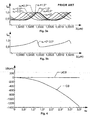
- Figures 3a shows a diagram over the relationship between the light transmission for different tilt angles ⁇ F of a particular narrow bandpass wavelength selective transmission filter element that has a Fabry-Perot structure, where a collimated light beam is used according to a known design.
- the horizontal axis of the diagram indicates the wavelength ⁇ and the intensity I AU of a sensor signal registered after the filter is represented along the vertical axis.
- the wavelength at which the transmission peaks occur here varies substantially depending on the filter tilt angle ⁇ F .
- the light transmission has a relatively strong angular dependency.
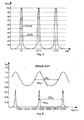
- Figures 3b shows another diagram over the relationship between the light transmission for different tilt angles ⁇ F of the same filter element as in the figure 3a .
- the filter element is arranged according to the invention, such that the filter constitutes an exclusive intermediary element between a laser and a light sensor.
- the light signal passes directly from the laser, through the filter element and further directly to the sensor.
- the light from the laser represents an uncollimated flux.
- Figure 4 illustrates, by means of another diagram, the angular dependence of the locking wavelength for an uncollimated light beam UCB and a collimated light beam CB respectively.
- the horizontal axis indicates the filter tilt angle ⁇ F
- the vertical axis represents a center crossing wavelength shift ⁇ .
- ⁇ F the filter tilt angle
- ⁇ F the center crossing wavelength shift
- the diagram shows an example of a Fabry-Perot type of filter element with a relatively high finesse, i.e. the ratio FSR/FWHM is rather large.
- Figure 6 shows diagram where the horizontal axis indicates a wavelength ⁇ and the vertical axis represents a light intensity I AU detected after an etalon filter element of Fabry-Perot structure.
- a top-most diagram shows a light transmission graph for a conventional collimated light beam directed towards a filter with a finesse of 0,7, i.e. a relatively low value; and a bottom-most diagram shows a light transmission graph for a filter with a finesse of 30, i.e. a relatively high value.
- a set point, set 0,7 and set 30 respectively, around half the amplitude is used.
- the high finesse filter has a relatively steep slope around the set point set 30 .
- a capture range CR 30 i.e. the interval within which the wavelength may be tuned to the set point set 30 , becomes very asymmetric. This means that, in practice, only rather a small initial wavelength deviation can be handled, namely a deviation equal to the shortest fraction of the asymmetric capture range CR 30 from the set point set 30 .
- the low finesse etalon has a much more symmetric capture range CR 0,7 , and thus a wider effective tuning range.
- the slope is less steep and therefore the wavelength precision less accurate.
- the wavelength locker it is more important to have a broad tuning range of the wavelength locker than to obtain a relatively high wavelength precision.
- One example is when the etalon thickness, and hence resonance wavelength, is not well controlled. In this case it is desirable with a characteristic were the absolute value of the derivative is reasonable high, while the regions close to a maximum can be avoided. Provided that a collimated light beam is used, this means that a low finesse filter element is required. However, for this type of filter there are large regions in the characteristics were the locking slope is very low. Moreover, the sign of the slope varies between the regions within the capture range.
- Figure 7 shows a diagram where again the horizontal axis indicates a wavelength ⁇ and the vertical axis represents a light intensity I AU detected after an etalon filter element of Fabry-Perot structure.
- the design according to the invention is used, where an uncollimated light beam is directed towards the filter element.
- the slope around the set point set UCB is very steep, and consequently the wavelength ⁇ may be adjusted very precisely without an exceedingly precise power measurement.
- FIGs 8a-b further elucidate the differences in the characteristics of the prior art strategy and the proposed design.
- the figure 8a shows a light transmission diagram where the horizontal axis indicates a wavelength ⁇ and the vertical axis represents a light intensity I AU of a collimated light beam, which is detected after an etalon filter element of Fabry-Perot structure with a relatively low finesse. Regions to be avoided around the maxima and minima are designated by means of broken-line boxes. Hence, a tuning range TR CB is available between two of these neighboring boxes.
- the figure 8b shows a light transmission diagram according to one embodiment of the invention where an uncollimated light beam is transmitted through an etalon filter element of Fabry-Perot structure.
- the horizontal axis indicates a wavelength ⁇ and the vertical axis represents a light intensity I AU .
- regions to be avoided around the maxima and minima are designated by means of broken-line boxes.
- the available continuous tuning range TR UCB between two neighboring boxes is nearly twice as broad as in the example of the figure 8a , i.e. TR UCB ⁇ 2TR CB .
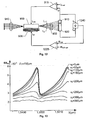
- a block diagram shows a first embodiment of a wavelength stabilized laser module.
- the laser module includes a semiconductor laser 900 and a thermo-electric cooling unit 905 associated therewith to control the wavelength of the light produced.
- thermo-electric cooling unit 905 associated therewith to control the wavelength of the light produced.
- alternative mechanisms are conceivable to adjust the wavelength, such as by means of an electrically tunable laser.
- the design also includes a first control loop, a second control loop and a narrow bandpass wavelength selective transmission filter element 930 of Fabry-Perot structure.
- the spectrum characteristics of the light L produced by the laser 900 depends on both a power control signal I bias and a temperature of the laser 900.
- the temperature is controlled by means of a wavelength control signal I tec to the thermo-electric cooling unit 905.
- the light L primarily exits the laser 900 via a front facet and a lens arrangement 940 and continues, for example into an optical fiber.
- the light L is also tapped off via a back facet in the form of a first and a second light signal L 1 and L 2 respectively, and is directed towards a first and a second sensor 910 and 920.
- the laser 900 is adapted to produce the first and second light signals L 1 , and L 2 as an uncollimated light flux.
- the first light signal L 1 constitutes a first fraction of a divergent light beam from the laser's 900 back facet
- the second light signal L 2 constitutes a second fraction of the divergent light beam from laser's 900 back facet.
- the first control loop includes the first sensor 910, which is adapted to produce a first electric signal I P in response to the first light signal L 1 from the laser 900.
- a power monitoring module 915 in the loop receives the first electric signal I P and a power set value I P-set representing a desired power control signal I bias to be delivered to the laser 900.
- the power monitoring module 915 produces the power control signal I bias in response to the first electric signal I P and the power set value I P-set .
- the power monitoring module 915 may implement a comparator function, such that if the first electric signal I P is smaller than the set value I P-set the power control signal I bias is increased, and vice versa.
- the second control loop includes the second sensor 920, which is adapted to produce a second electric signal I W in response to the second light signal L 2 from the laser. Nevertheless, the second light signal L 2 has first passed through the filter element 930, which is arranged to constitute an exclusive intermediary element between the laser 900 and the second sensor 920.
- a wavelength-monitoring module 925 in the second control loop receives the second electric signal I W and a wavelength set value I W-set . Based on the second electric signal I W , value relative to the wavelength set value I W-set , the wavelength monitoring module 925 produces the wavelength control signal I tec .
- the wavelength-monitoring module 925 may represent a comparator function.
- an appropriate wavelength set value I W-set for the laser 900 which is adapted to transmit on a particular channel Chn (see the figure 1 ) is a current value I W that corresponds to a desired wavelength ⁇ n for this channel.
- Figure 10 shows a diagram that illustrates the relationship between the second electric signal I W and the wavelength ⁇ of the laser light L.
- the wavelength set value I W-set also represents approximately half the peak value I Wp of the second electric signal I W .
- the second light signal L 2 passes through the filter element 930 to a light-sensing surface of the second sensor 920, and the first light signal L 1 directly illuminates a light-sensing surface of the first sensor 910.
- a robust wavelength stabilization of the laser 900 is accomplished, such that the light L has a well-defined wavelength over the entire life of the laser 900.
- FIG 11 schematically illustrates the geometric relationships between the laser 900, the filter element 930 and the second sensor 920 of the wavelength stabilized laser module according to the invention.
- the filter element 930 is presumed to have a filter tilt angle ⁇ F towards a laser central axis A L of the laser 900 (i.e. the main direction along which light is emitted).
- the filter tilt angle ⁇ F should be as small as possible.
- the ideal filter tilt angle ⁇ F is zero.
- a filter tilt angle ⁇ F which is smaller than or equal to 7 degrees is acceptable according to the invention.
- the second sensor 920 and the filter element 930 are arranged relative to the laser 900, such that a light ray I r from the laser 900 may pass perpendicularly N F to the light incident and exit surfaces of the filter element 930 through the filter element 930 to the light-sensing surface S 2 of the second sensor 920.
- this orientation of the filter element 930 and the second sensor 920 renders it possible for a radial light ray I r from the laser 900 (which may be regarded as a point source) to pass a shortest distance through the filter element 930 and strike the light-sensing surface S 2 .
- This potentially, produces a strong electric signal (which is the second electric signal I W in the figure 9 ).
- the second sensor 920 has a light-sensing surface S 2 , which may have a tilt angle ⁇ 2 towards the laser central axis A L .
- the tilt angle ⁇ 2 is essentially equal to the filter tilt angle ⁇ F , such that the light-sensing surface S 2 is parallel to the light incident and exit surfaces of the filter element 930. Thereby, a light ray passing perpendicularly through the filter element 930 will also strike the light-sensing surface S 2 at a right angle, which vouches for an even stronger resulting electric signal.
- a central axis A 2 of the light-sensing surface S 2 is also essentially aligned with a line N F from a light emitting point of the laser 900, which is perpendicular to the light incident and exit surfaces of the filter element 930.
- the light ray I r will strike the center of the light-sensing surface S 2 , and thus further improve the quality of the second electric signal I W .
- the filter element 930 should be arranged, such that a first distance D 1 between the laser 900 and the light incident surface of the filter element 930 is less than, or equal to, 1600 ⁇ m.
- other measurements and simulations have shown that the central axis A 2 of the second sensor 920 should not be displaced, i.e. offset, by more than a distance X 2 equal to 350 ⁇ m with respect to the laser central axis A L .
- the longest acceptable offset distance x 2 depends on the dimensions of the second sensor's 920 light-sensing surface S 2 , such that a larger surface S 2 , tolerates a longer offset distance x 2 , and vice versa.
- a large monitor size i.e. a light-sensing surface S 2 , with a large area
- a large monitor is also less sensitive to angular mismatches than a smaller ditto.
- large monitors are expensive, i.a. due to a lower yield.
- an excessive light-sensing surface decreases the relative amplitude of the registered characteristic. Therefore, the monitor size is a parameter which must be optimized. According to measurements and simulations (see figures 17, 18 and 19 ), it is advantageous if the second sensor's 920 light sensing surface S 2 has an outline with dimensions in the interval 50 ⁇ m to 400 ⁇ m.
- the surface should preferably be essentially rectangular and have a width w 2 , which is approximately two times the height, say 400 ⁇ m wide and 200 ⁇ m high. (The width w 2 is here measured along the direction of any offset distance x 2 with respect to the laser central axis A L ).
- a sensor of these dimensions is namely relatively unproblematic to fabricate. Furthermore, a sensor of this size has characteristics that are favorable with respect to angular dependence and relative amplitude.
- a distance D 2 between the light exit surface of the filter element 930 and the second sensor 920 is less critical. However, the invention has proven to be efficient up to a distance D 2 of 1000 ⁇ m. Likewise, a thickness d of the filter element 930 may be selected relatively freely, say in the interval 300 ⁇ m to 1000 ⁇ m.
- the semiconductor laser 900 produces light, which has a wavelength in the interval 1,5480 ⁇ m to 1,5525 ⁇ m. Naturally, if light is used, which has different spectral properties, this affects the dimensions and measures, so that a shorter wavelength generally requires a reduction of the geometry, and vice versa. In any case, the invention is at least applicable over the entire C- and L-bands, i.e. 1530 nm to 1565 nm and 1570 to 1610 nm respectively.
- Figure 12 shows a block diagram over a wavelength stabilized laser module according to a second embodiment of the invention.
- the units and components whose reference signs occur also in the figure 9 designate the same units as discussed above with reference to this figure.
- the second control loop includes a division unit 1240 and an alternative wavelength-monitoring module 1225.
- the wavelength-monitoring module 1225 receives the composite control signal R WP and a composite wavelength set value I W-set . In response to these signals, the wavelength-monitoring module 1225 produces the wavelength control signal I tec .
- An advantage attained by means of this design is that the laser's 900 temperature will be controlled towards a value given by the composite wavelength set value I W-set irrespective of the first electric signal's I P level.
- a diagram here illustrates the sensitivity of the displacement of the second sensor 920 according to one embodiment of the invention.
- the horizontal axis indicates the wavelength ⁇ of the light from the laser 900, and the vertical axis shows an electric signal SS AU produced by the second sensor 920.
- the distance D 1 between the laser 900 and the filter element 930 is 700 ⁇ m.
- offset distances x 2 of 250 ⁇ m or less result in clearly distinguishable characteristics.
- the invention is relatively insensitive to filter tilt angles ⁇ F up to seven degrees for distances D 1 between the laser 900 and the filter element 930 up to 1600 ⁇ m.
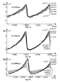
- Each of the diagrams in the figures 14-16 indicate the wavelength ⁇ along the horizontal axis and show an amplitude SS AU of the second electric signal I W produced by the second sensor 920 along the vertical axis.
- the distance D 1 between the laser 900 and the filter element 930 is 100 ⁇ m, and in the figures 15 and 16 this distance is 700 ⁇ m and 1600 ⁇ m respectively.
- the second electric signal I W produced by the second sensor 920 has a clearly distinguishable characteristics for widths w 2 of the second sensor's 920 light-sensing surface S 2 in the interval 50 ⁇ m to 400 ⁇ m.
- Each of the diagrams also here indicate the wavelength ⁇ along the horizontal axis and show amplitude SS AU of the electric signal I W along the vertical axis.
- the width w 2 is 50 ⁇ m
- this measure is 200 ⁇ m and 400 ⁇ m respectively.
- Figure 20 shows a diagram, where measurements of the filter element's 930 light transmission have been registered prior to assembly as well as after assembly in an arrangement according to one embodiment of the invention.
- the horizontal axis indicates a wavelength ⁇
- a left-most vertical axis shows an amplitude SS AU of the second electric signal I W produced by the second sensor 920
- a right-most vertical axis shows a filter reflectivity F R in dB (which represents an inverted measure of the transmission through the filter element 930).
- a dashed graph represents a relationship between the filter reflectivity F R and the wavelength ⁇ for the filter element 930 prior to the assembly.
- a solid graph represents a relationship between the second electric signal I W and the wavelength ⁇ , i.e. when the filter element has been arranged according to one embodiment of the invention.
- figure 21 shows a diagram, which illustrates the relationship between an actual laser wavelength ⁇ and the laser's case temperature T according to one embodiment of the invention.
- the horizontal axis indicates the temperature T
- the vertical axis shows the wavelength ⁇ .
- the wavelength ⁇ is plotted for each individual temperature value T as a thin solid graph, and an average temperature T is drawn as a bold solid graph.
- the latter illustrates the general relationship between the laser temperature T and the wavelength ⁇ of the light produced by the laser.
- the wavelength ⁇ increases with an increasing temperature T.
Landscapes
- Physics & Mathematics (AREA)
- Electromagnetism (AREA)
- Condensed Matter Physics & Semiconductors (AREA)
- General Physics & Mathematics (AREA)
- Optics & Photonics (AREA)
- Engineering & Computer Science (AREA)
- Computer Networks & Wireless Communication (AREA)
- Signal Processing (AREA)
- Semiconductor Lasers (AREA)
- Lasers (AREA)
Abstract
Description
- The present invention relates generally to the production of laser signals which are suitable for wavelength division multiplex optical transmission systems. More particularly the invention relates to a wavelength stabilized laser module according to the preamble of
claim 1. - In an optical transmission system information is represented by light pulses which are transmitted over optical fibers. Furthermore, a single fiber may be used to transmit light of multiple wavelengths in order to obtain a high capacity and a high flexibility. Typically, semiconductor lasers are used to produce this light. In its most simple form, a wavelength division multiplexed (WDM) optical transmission system includes a number of transmission channels, where each channel transmits at a well-defined wavelength.
Figure 1 schematically illustrates a WDM transmission system, where a number of different channels Ch1, Ch-2, ..., Chn are combined into a compound signal by means of an optical multiplexer (MUX) 110. The compound signal is then transmitted through anoptical fiber 130, and at one or more end locations the individual channels Ch1, Ch2, ..., Chn are separated out by means of an optical demultiplexer (DEMUX) 120. Normally, the channels Ch1, Ch2, ..., Chn are placed at standardized wavelengths λ1, λ2, ..., λn with a particular wavelength separation Δλ between each channel. In a dense WDM (DWDM) system the channel separation is 100 GHz, which corresponds to a wavelength separation ΔX of approximately 0.8nm, seefigure 2 . The maximal allowed wavelength error is, of course considerably smaller, say 100 pm. This places very strict requirements on the accuracy and stability of the laser's wavelength. The relative accuracy needled is in the order of 0.005 percent or better. Typical semiconductor lasers incorporate a grating to obtain a stable single wavelength. Nevertheless, it is difficult to guarantee a particular wavelength over the lifetime of the component. Therefore it is important that mechanisms be provided, which monitor the laser wavelength and force it to its nominal value. These mechanisms normally include at least one feedback control loop that monitors and stabilizes the laser wavelength by locking it to a stable reference. - The prior art includes many different examples as how to accomplish a so-called wavelength locker for stabilizing a laser. One common element to obtain a wavelength reference is to use a Fabry-Perot etalon. This element has two parallel and partially reflecting surfaces. A common implementation is to use quarts (or a similar material) where a reflecting layer is deposited on one or both of the two surfaces. Light that is transmitted through the etalon has a periodic transmission dependence on the wavelength. The classical way to make use of a Fabry-Perot etalon is to direct a collimated, or nearly collimated, beam towards the etalon and detect the light which is transmitted through the etalon. By adjusting the reflectance of the mirrors it is possible to change the finesse of the etalon. The diagram in
figure 5 illustrates the definition of the term finesse for a relatively high value. The horizontal axis shows fringe orders FO: m, m+1, m+2 etc. for monochromatic light passing through the etalon. The vertical axis shows the relative light transmission T in percent. For higher values, the finesse may be defined as the ratio of the separation of adjacent maxima, (the free spectral range, FSR), to the full width at half the maximum (FWHM), i.e. at T=50%. Thus, narrow and well-separated peaks are indicative of a high finesse, whereas a low finesse value is equivalent to much less well-defined peaks. In fact, more strictly, the finesse parameter is defined as the ratio π√R/(1-R), where R denotes the reflectance of the two parallel surfaces. This definition is applicable also to low finesse values. - In addition to the front facet, light may normally also be taken from the back facet of a semiconductor laser. This back-facet light is readily accessible, and may be used to measure and monitor the light produced by the laser. For instance, the back-facet light can be utilized to adjust the laser's drive current, such that the laser generates a constant output power. Moreover, the back-facet light may be used to accomplish a wavelength locking function.
- The
patent document EP 1 133 034 describes a wavelength stabilized laser module where light from the back facet is collimated by a lens. One part of the collimated beam is passed through an etalon-type filter to a first photoelectric converter, and another part of the collimated beam is transmitted directly to a second photoelectric converter. Hence, the first photoelectric converter measures light which has been transmitted through the etalon, whereas the second photoelectric converter samples unfiltered light from the laser so as to enable a power control. This solution presumes a parallel luminous flux, and therefore requires a lens or the like. However, such a lens arrangement is relatively expensive and uses considerable space. Moreover, the lens may cause reflections from the etalon and the photodetector to be reflected back and focused into the laser. This in turn, risks seriously degrading the laser's performance. According to the design of this document, the transmitted light shows the traditional Airy function dependence with the wavelength. It is therefore clear that a low-finesse etalon is required in order to obtain a simple locking to the function. - The
U.S. patent 5,825,792 discloses a wavelength monitoring and control assembly for WDM optical transmission systems. Also here a lens is proposed to control the divergence of the light from the laser incident on a filter element in the form of a Fabry-Perot etalon. However, in this case the beam need not be completely collimated. The lens is therefore optional. The balance between two detectors is used to control the laser. Also here a relatively low-finesse etalon is needed for a proper function. Moreover, the detectors are placed symmetrical to the output light from the laser and both detectors receive light which has passed through the etalon. The laser wavelength is tuned by adjusting the angle of the etalon. Naturally, this renders the design very sensitive to any uncontrolled tilting of the etalon. - The object of the present invention is therefore to provide a cost efficient, compact and robust wavelength stabilization for a laser module, which alleviates the above problems, and thus enables a reliable and efficient laser function over a broad range of filter angles.
- A wavelength stabilized laser module according to the invention is defined in
claim 1. - According to one aspect of the invention the object is achieved by the laser module as initially described, wherein the first sensor is arranged such that the first light signal directly illuminates a light-sensing surface of the sensor, i.e. without passing through the filter element.
- An important advantage attained by means of this laser module is that a filter element may be used, which both has steep slopes (i.e. a feature associated with a high-finesse etalon) and a wide symmetric capture range (i.e. a feature normally associated with low-finesse etalons). The design is also relatively insensitive to variations in the relative angle between the filter element and the laser.
- According to a preferred embodiment of this aspect of the invention, the second control loop includes a thermo-electric cooling unit which is associated with the laser. The thermo-electric cooling unit is adapted to receive the wavelength control signal and in response thereto adjust the temperature of the laser. This adjustment, in turn, results in a wavelength change.
- According to another preferred embodiment of this aspect of the invention, the laser module includes a division unit, which is adapted to receive the first and the second electric signals. In response to these signals the division unit produces a composite control signal that is indicative of a ratio between the first electric signal and the second electric signal. The wavelength-monitoring module is adapted to receive the composite control signal, and in response thereto produce the wavelength control signal. By means of this design, the control current ratio is constant and the laser temperature will be tuned to the wavelength set value irrespective of the first electric signal, i.e. the power control current level.
- According to yet another preferred embodiment of this aspect of the invention, the laser is adapted to produce the first and second light signals in the form of an uncollimated light flux. More preferably, the first light signal constitutes a first fraction of a divergent light beam from the laser while the second light signal constitutes a second fraction of this light beam. Thereby, a very compact and simple overall design is attained.
- According to yet another preferred embodiment of this aspect of the invention, the second sensor and the filter element are arranged relative to the laser, such that a light ray from the laser passes perpendicularly through the filter element to the light-sensing surface of the second sensor. Namely, thereby, a light ray emitted radially from the laser may travel a shortest way through the filter element to the second sensor. This, in turn, results in comparatively good transmission efficiency from the filter element to the second sensor.
- According to another preferred embodiment of this aspect of the invention, the filter element may have a non-zero filter tilt angle towards a laser central axis of the laser, and the light-sensing surface of the second sensor has a tilt angle towards the laser central axis, which is essentially equal to the filter tilt angle. This enhances the efficiency of the second sensor to some extent.
- According to still another preferred embodiment of this aspect of the invention, the filter element has a filter tilt angle of seven degrees or less. Although a small filter tilt angle is generally preferable, the invention performs well over the entire range of angles between zero and seven degrees, and consequently allows a relatively large tolerance to any uncontrolled tilting of the filter element.
- According to another preferred embodiment of this aspect of the invention, the laser is adapted to produce light, which has a wavelength in the interval 1530 nm to 1610 nm, e.g. in the C-band (1530-1565 nm) or in the L-band (1570-1610 nm). Moreover, the filter element is arranged, such that its light incident surface is located within 1600 µm from the laser. Hence, the invention provides a large degree of flexibility in terms of wavelength and geometry.
- According to yet another preferred embodiment of this aspect of the invention, the light-sensing surface of the second sensor has an essentially rectangular outline with dimensions, which lie in the
interval 50 µm to 400 µm, preferably above 200 µm. Namely, this sensor size strikes good balance between cost effectiveness/yield and angular sensitivity. - According to still another preferred embodiment of this aspect of the invention, a central axis of the second sensor is displaced at an offset distance with respect to the laser central axis, which is less than or equal to 350 µm. Thus, a relatively large offset of the second sensor can be accepted before the electric signal there from deteriorates to an unacceptably low quality.
- According to another preferred embodiment of this aspect of the invention, the filter element has a thickness ranging from 300 µm to 1000 µm. Moreover, the filter element is arranged with the light exit surface within 1000 µm from the second sensor. Thus, the invention also allows relatively large geometry flexibility on the light-exit side.
- To sum up, the invention provides compact and cost efficient laser wavelength stabilization over a broad tuning range. A design according to the proposed solution is also reliable, since there is no lens (or equivalent collimating element) between the laser and the filter element, and therefore the risk of back reflections from the sensor via the filter being focused into the laser is eliminated.
- Further advantages, advantageous features and applications of the present invention will be apparent from the following description and the dependent claims.
- The present invention is now to be explained more closely by means of preferred embodiments, which are disclosed as examples, and with reference to the attached drawings.
- Figure 1
- shows a schematic block diagram over a per se known WDM optical transmission system,
- Figure 2
- shows a diagram which illustrates the wavelength separation between the optical channels of the system in
figure 1 , - Figures 3a-b
- show diagrams illustrating the differences in angular sensitivity for a collimated light beam used in the prior art and an uncollimated beam used according to one embodiment of the invention,
- Figure 4
- illustrates, by means of another diagram, the angular dependence of the locking wavelength for an uncollimated light beam and a collimated light beam respectively,
- Figure 5
- defines the finesse parameter, which is used as a figure of the merit for the transmission bandwidth of a Fabry-Perot interferometer,
- Figure 6
- show diagrams over per se known wavelength de- pendencies, with reference to which the finesse
- Figure 7
- parameter is further elaborated upon, shows a diagram illustrating the capture range according to one embodiment of the invention,
- Figures 8a-b
- show diagrams which elucidate the differences in the tuning ranges attainable by means of a collimated light beam used according to the prior art respective an uncollimated light beam used according to one embodiment of the invention,
- Figure 9
- shows a block diagram over a wavelength stabi- lized laser module according to a first embodiment of the invention,
- Figure 10
- shows a diagram illustrating how an appropriate set value is selected for the wavelength control signal according to one embodiment of the inven- tion,
- Figure 11
- schematically illustrates the geometry of the wavelength stabilized laser module according to the invention,
- Figure 12
- shows a block diagram over a wavelength stabi- lized laser module according to a second embo- diment of the invention,
- Figure 13
- shows a diagram which illustrates the sensitivity of the displacement of the second sensor accor- ding to one embodiment of the invention,
- Figures 14-16
- show diagrams which illustrate the sensitivity of the distance between the laser and the filter ele- ment according to one embodiment of the inven- tion,
- Figures 17-19
- show diagrams which illustrate the sensitivity of the dimensions of the second sensor according to one embodiment of the invention,
- Figure 20
- shows a diagram representing measurements of the light transmission prior to assembly respective after assembly of a filter element in an arrange- ment according to one embodiment of the inven- tion, and
- Figure 21
- shows a diagram which illustrates the relationship between an actual laser wavelength and the laser's case temperature according to one embo- diment of the invention.
-
Figures 3a shows a diagram over the relationship between the light transmission for different tilt angles αF of a particular narrow bandpass wavelength selective transmission filter element that has a Fabry-Perot structure, where a collimated light beam is used according to a known design. The horizontal axis of the diagram indicates the wavelength λ and the intensity IAU of a sensor signal registered after the filter is represented along the vertical axis. As can be seen, the wavelength at which the transmission peaks occur here varies substantially depending on the filter tilt angle αF. For example, a filter tilt angle αF equal to 0° results in a first transmission peak around the wavelength λ=1,5499 µm, whereas for a filter angle αF of 3,0°, this peak occurs around α=1,5492 µm. Thus, the light transmission has a relatively strong angular dependency. -
Figures 3b shows another diagram over the relationship between the light transmission for different tilt angles αF of the same filter element as in thefigure 3a . Here, the filter element is arranged according to the invention, such that the filter constitutes an exclusive intermediary element between a laser and a light sensor. Hence, the light signal passes directly from the laser, through the filter element and further directly to the sensor. Preferably, the light from the laser represents an uncollimated flux. The filter element is tilted in angular steps of 0,5°, from 0° to 3,0°; however, there is no noticeable difference in the transmission profile. Instead, an accentuated transmission peak remained stable at approximately λ=1,5498 µm for all filter angles αF. Consequently, the invention is insensitive for filter tilting, at least for relatively small tilt angles. -
Figure 4 illustrates, by means of another diagram, the angular dependence of the locking wavelength for an uncollimated light beam UCB and a collimated light beam CB respectively. Here, the horizontal axis indicates the filter tilt angle αF, and the vertical axis represents a center crossing wavelength shift δλ. For the collimated light beam CB a wavelength shift δλ of 50 pm occurs already at a filter tilt angle αF of 0,6°. According to one embodiment of the invention, where an uncollimated light beam UCB is used, a tilt angle of αF=3,5° merely results in a wavelength shift δλ of 3 pm. In fact, when UCB is used, a filter tilt angle as large as αF=7,0° can be allowed before a wavelength shift δλ of 50 pm is reached. The corresponding value for the collimated light beam CB is 1350 pm (i.e. at αF=7,0°). - Returning now to the
figure 5 , we find that the diagram shows an example of a Fabry-Perot type of filter element with a relatively high finesse, i.e. the ratio FSR/FWHM is rather large. -
Figure 6 shows diagram where the horizontal axis indicates a wavelength λ and the vertical axis represents a light intensity IAU detected after an etalon filter element of Fabry-Perot structure. A top-most diagram shows a light transmission graph for a conventional collimated light beam directed towards a filter with a finesse of 0,7, i.e. a relatively low value; and a bottom-most diagram shows a light transmission graph for a filter with a finesse of 30, i.e. a relatively high value. In both cases, a set point, set0,7 and set30 respectively, around half the amplitude is used. The high finesse filter has a relatively steep slope around the set point set30. This is preferable because thereby the wavelength λ can be adjusted very precisely without an extremely precise power measurement being required. However, a capture range CR30, i.e. the interval within which the wavelength may be tuned to the set point set30, becomes very asymmetric. This means that, in practice, only rather a small initial wavelength deviation can be handled, namely a deviation equal to the shortest fraction of the asymmetric capture range CR30 from the set point set30. As is apparent from the top-most diagram, the low finesse etalon has a much more symmetric capture range CR0,7, and thus a wider effective tuning range. However here, the slope is less steep and therefore the wavelength precision less accurate. - In some applications it is more important to have a broad tuning range of the wavelength locker than to obtain a relatively high wavelength precision. One example is when the etalon thickness, and hence resonance wavelength, is not well controlled. In this case it is desirable with a characteristic were the absolute value of the derivative is reasonable high, while the regions close to a maximum can be avoided. Provided that a collimated light beam is used, this means that a low finesse filter element is required. However, for this type of filter there are large regions in the characteristics were the locking slope is very low. Moreover, the sign of the slope varies between the regions within the capture range.
-
Figure 7 shows a diagram where again the horizontal axis indicates a wavelength λ and the vertical axis represents a light intensity IAU detected after an etalon filter element of Fabry-Perot structure. Here, however, the design according to the invention is used, where an uncollimated light beam is directed towards the filter element. As can be seen from the graph, if a set point setUCB is selected approximately around half the amplitude, the attainable capture range CRUCB is relatively symmetric around this set point setUCB. At the same time, the slope around the set point setUCB is very steep, and consequently the wavelength λ may be adjusted very precisely without an exceedingly precise power measurement. -
Figures 8a-b further elucidate the differences in the characteristics of the prior art strategy and the proposed design. Thefigure 8a shows a light transmission diagram where the horizontal axis indicates a wavelength λ and the vertical axis represents a light intensity IAU of a collimated light beam, which is detected after an etalon filter element of Fabry-Perot structure with a relatively low finesse. Regions to be avoided around the maxima and minima are designated by means of broken-line boxes. Hence, a tuning range TRCB is available between two of these neighboring boxes. - The
figure 8b shows a light transmission diagram according to one embodiment of the invention where an uncollimated light beam is transmitted through an etalon filter element of Fabry-Perot structure. The horizontal axis indicates a wavelength λ and the vertical axis represents a light intensity IAU. Again, regions to be avoided around the maxima and minima are designated by means of broken-line boxes. Here however, the available continuous tuning range TRUCB between two neighboring boxes is nearly twice as broad as in the example of thefigure 8a , i.e. TRUCB≈2TRCB. - The general design of a laser module according to the invention will now be discussed with reference to
figure 9 . Here, a block diagram shows a first embodiment of a wavelength stabilized laser module. The laser module includes asemiconductor laser 900 and a thermo-electric cooling unit 905 associated therewith to control the wavelength of the light produced. However, according to the invention, alternative mechanisms are conceivable to adjust the wavelength, such as by means of an electrically tunable laser. In any case, the design also includes a first control loop, a second control loop and a narrow bandpass wavelength selectivetransmission filter element 930 of Fabry-Perot structure. - It is presumed that the spectrum characteristics of the light L produced by the
laser 900 depends on both a power control signal Ibias and a temperature of thelaser 900. The temperature is controlled by means of a wavelength control signal Itec to the thermo-electric cooling unit 905. The light L primarily exits thelaser 900 via a front facet and alens arrangement 940 and continues, for example into an optical fiber. However, the light L is also tapped off via a back facet in the form of a first and a second light signal L1 and L2 respectively, and is directed towards a first and asecond sensor laser 900 is adapted to produce the first and second light signals L1, and L2 as an uncollimated light flux. For example, the first light signal L1 constitutes a first fraction of a divergent light beam from the laser's 900 back facet, and the second light signal L2 constitutes a second fraction of the divergent light beam from laser's 900 back facet. - The first control loop, in turn, includes the
first sensor 910, which is adapted to produce a first electric signal IP in response to the first light signal L1 from thelaser 900. Apower monitoring module 915 in the loop receives the first electric signal IP and a power set value IP-set representing a desired power control signal Ibias to be delivered to thelaser 900. Thepower monitoring module 915 produces the power control signal Ibias in response to the first electric signal IP and the power set value IP-set. For instance, thepower monitoring module 915 may implement a comparator function, such that if the first electric signal IP is smaller than the set value IP-set the power control signal Ibias is increased, and vice versa. - Correspondingly, the second control loop includes the
second sensor 920, which is adapted to produce a second electric signal IW in response to the second light signal L2 from the laser. Nevertheless, the second light signal L2 has first passed through thefilter element 930, which is arranged to constitute an exclusive intermediary element between thelaser 900 and thesecond sensor 920. A wavelength-monitoring module 925 in the second control loop receives the second electric signal IW and a wavelength set value IW-set. Based on the second electric signal IW, value relative to the wavelength set value IW-set, thewavelength monitoring module 925 produces the wavelength control signal Itec. Analogous to the above-described power-monitoringmodule 915, the wavelength-monitoring module 925 may represent a comparator function. - Of course, an appropriate wavelength set value IW-set for the
laser 900, which is adapted to transmit on a particular channel Chn (see thefigure 1 ) is a current value IW that corresponds to a desired wavelength λn for this channel.Figure 10 shows a diagram that illustrates the relationship between the second electric signal IW and the wavelength λ of the laser light L. Preferably, the wavelength set value IW-set also represents approximately half the peak value IWp of the second electric signal IW. - Thus, returning now to
figure 9 , according to the invention the second light signal L2 passes through thefilter element 930 to a light-sensing surface of thesecond sensor 920, and the first light signal L1 directly illuminates a light-sensing surface of thefirst sensor 910. Thereby, a robust wavelength stabilization of thelaser 900 is accomplished, such that the light L has a well-defined wavelength over the entire life of thelaser 900. -
Figure 11 schematically illustrates the geometric relationships between thelaser 900, thefilter element 930 and thesecond sensor 920 of the wavelength stabilized laser module according to the invention. Thefilter element 930 is presumed to have a filter tilt angle αF towards a laser central axis AL of the laser 900 (i.e. the main direction along which light is emitted). In order to obtain an optimal performance, the filter tilt angle αF should be as small as possible. Hence, the ideal filter tilt angle αF is zero. Nevertheless, a filter tilt angle αF which is smaller than or equal to 7 degrees is acceptable according to the invention. - According to a preferred embodiment of the invention, the
second sensor 920 and thefilter element 930 are arranged relative to thelaser 900, such that a light ray Ir from thelaser 900 may pass perpendicularly NF to the light incident and exit surfaces of thefilter element 930 through thefilter element 930 to the light-sensing surface S2 of thesecond sensor 920. Namely, this orientation of thefilter element 930 and thesecond sensor 920 renders it possible for a radial light ray Ir from the laser 900 (which may be regarded as a point source) to pass a shortest distance through thefilter element 930 and strike the light-sensing surface S2. This, potentially, produces a strong electric signal (which is the second electric signal IW in thefigure 9 ). - The
second sensor 920 has a light-sensing surface S2, which may have a tilt angle α2 towards the laser central axis AL. According to another preferred embodiment of the invention, the tilt angle α2 is essentially equal to the filter tilt angle αF, such that the light-sensing surface S2 is parallel to the light incident and exit surfaces of thefilter element 930. Thereby, a light ray passing perpendicularly through thefilter element 930 will also strike the light-sensing surface S2 at a right angle, which vouches for an even stronger resulting electric signal. - Moreover, it is preferable if a central axis A2 of the light-sensing surface S2 is also essentially aligned with a line NF from a light emitting point of the
laser 900, which is perpendicular to the light incident and exit surfaces of thefilter element 930. Thereby, the light ray Ir will strike the center of the light-sensing surface S2, and thus further improve the quality of the second electric signal IW. - Measurements and simulations (see
figures 14, 15 and 16 ) have confirmed that thefilter element 930 should be arranged, such that a first distance D1 between thelaser 900 and the light incident surface of thefilter element 930 is less than, or equal to, 1600 µm. Furthermore, other measurements and simulations (seefigure 13 ) have shown that the central axis A2 of thesecond sensor 920 should not be displaced, i.e. offset, by more than a distance X2 equal to 350 µm with respect to the laser central axis AL. Of course, the longest acceptable offset distance x2 depends on the dimensions of the second sensor's 920 light-sensing surface S2, such that a larger surface S2, tolerates a longer offset distance x2, and vice versa. - Generally, a large monitor size (i.e. a light-sensing surface S2, with a large area) is preferable because this enables a strong resulting electric signal. A large monitor is also less sensitive to angular mismatches than a smaller ditto. However, large monitors are expensive, i.a. due to a lower yield. Additionally, an excessive light-sensing surface decreases the relative amplitude of the registered characteristic. Therefore, the monitor size is a parameter which must be optimized. According to measurements and simulations (see
figures 17, 18 and 19 ), it is advantageous if the second sensor's 920 light sensing surface S2 has an outline with dimensions in theinterval 50 µm to 400 µm. Moreover, the surface should preferably be essentially rectangular and have a width w2, which is approximately two times the height, say 400 µm wide and 200 µm high. (The width w2 is here measured along the direction of any offset distance x2 with respect to the laser central axis AL). A sensor of these dimensions is namely relatively unproblematic to fabricate. Furthermore, a sensor of this size has characteristics that are favorable with respect to angular dependence and relative amplitude. - A distance D2 between the light exit surface of the
filter element 930 and thesecond sensor 920 is less critical. However, the invention has proven to be efficient up to a distance D2 of 1000 µm. Likewise, a thickness d of thefilter element 930 may be selected relatively freely, say in the interval 300 µm to 1000 µm. - The dimensions and measures discussed above with reference to the
figure 11 presume that thesemiconductor laser 900 produces light, which has a wavelength in theinterval 1,5480 µm to 1,5525 µm. Naturally, if light is used, which has different spectral properties, this affects the dimensions and measures, so that a shorter wavelength generally requires a reduction of the geometry, and vice versa. In any case, the invention is at least applicable over the entire C- and L-bands, i.e. 1530 nm to 1565 nm and 1570 to 1610 nm respectively. -
Figure 12 shows a block diagram over a wavelength stabilized laser module according to a second embodiment of the invention. The units and components whose reference signs occur also in thefigure 9 designate the same units as discussed above with reference to this figure. Thus, the only difference between this embodiment of the invention and the first embodiment is that the second control loop includes adivision unit 1240 and an alternative wavelength-monitoring module 1225. - The
division unit 1240 receives the first electric signal IP and the second electric signal IW. In response to these signals, theunit 1240 produces a composite control signal RWP, which is indicative of a ratio between the first electric signal IP and the second electric signal IW, i.e. RWP,=c·IP/IW, where c is a scale factor, say c=1. The wavelength-monitoring module 1225 receives the composite control signal RWP and a composite wavelength set value IW-set. In response to these signals, the wavelength-monitoring module 1225 produces the wavelength control signal Itec. An advantage attained by means of this design is that the laser's 900 temperature will be controlled towards a value given by the composite wavelength set value IW-set irrespective of the first electric signal's IP level. - Returning briefly now to the
figure 13 , a diagram here illustrates the sensitivity of the displacement of thesecond sensor 920 according to one embodiment of the invention. The horizontal axis indicates the wavelength λ of the light from thelaser 900, and the vertical axis shows an electric signal SSAU produced by thesecond sensor 920. The distance D1 between thelaser 900 and thefilter element 930 is 700 µm. As can be seen, offset distances x2 of 250 µm or less result in clearly distinguishable characteristics. However, the design is operable at least up to offset distances x2=350 µm for larger distances D1. - Returning also to the
figures 14-16 , we see that the invention is relatively insensitive to filter tilt angles αF up to seven degrees for distances D1 between thelaser 900 and thefilter element 930 up to 1600 µm. Each of the diagrams in thefigures 14-16 indicate the wavelength λ along the horizontal axis and show an amplitude SSAU of the second electric signal IW produced by thesecond sensor 920 along the vertical axis. In thefigure 14 the distance D1 between thelaser 900 and thefilter element 930 is 100 µm, and in thefigures 15 and 16 this distance is 700 µm and 1600 µm respectively. - Similarly, by studying the
figures 17-19 we find that the second electric signal IW produced by thesecond sensor 920 has a clearly distinguishable characteristics for widths w2 of the second sensor's 920 light-sensing surface S2 in theinterval 50 µm to 400 µm. Each of the diagrams also here indicate the wavelength λ along the horizontal axis and show amplitude SSAU of the electric signal IW along the vertical axis. In thefigure 17 the width w2 is 50 µm, and in thefigures 18 and 19 , this measure is 200 µm and 400 µm respectively. -
Figure 20 shows a diagram, where measurements of the filter element's 930 light transmission have been registered prior to assembly as well as after assembly in an arrangement according to one embodiment of the invention. The horizontal axis indicates a wavelength λ, a left-most vertical axis shows an amplitude SSAU of the second electric signal IW produced by thesecond sensor 920 and a right-most vertical axis shows a filter reflectivity FR in dB (which represents an inverted measure of the transmission through the filter element 930). - A dashed graph represents a relationship between the filter reflectivity FR and the wavelength λ for the
filter element 930 prior to the assembly. A solid graph represents a relationship between the second electric signal IW and the wavelength λ, i.e. when the filter element has been arranged according to one embodiment of the invention. Clearly, the solid graph shows a transmission peak around the wavelength λ=1546,6 nm. It is also apparent from the diagram that theunassembled filter element 930 has a transmission peak (i.e. a reflectance dip) approximately at this wavelength λ. Consequently, the arrangement is well tuned. - Finally,
figure 21 shows a diagram, which illustrates the relationship between an actual laser wavelength λ and the laser's case temperature T according to one embodiment of the invention. Here, the horizontal axis indicates the temperature T, and the vertical axis shows the wavelength λ. The wavelength λ is plotted for each individual temperature value T as a thin solid graph, and an average temperature T is drawn as a bold solid graph. The latter illustrates the general relationship between the laser temperature T and the wavelength λ of the light produced by the laser. Apparently, the wavelength λ increases with an increasing temperature T. - The term "comprises/comprising" when used in this specification is taken to specify the presence of stated features, integers, steps or components. However, the term does not preclude the presence or addition of one or more additional features, integers, steps or components or groups thereof.
- The invention is not restricted to the described embodiments in the figures, but may be varied freely within the scope of the claims.
Claims (12)
- A wavelength stabilized laser module comprising:a semiconductor laser (900) adapted to produce a light signal (L);a first control loop including a first sensor (910) adapted to produce a first electric signal (Ip) in response to a first light signal (L1) from the laser (900); and a power monitoring module (915) adapted to receive the first electric signal (IP), and in response thereto produce a power control signal (Ibias) to the laser (900);a second control loop including a second sensor (920) adapted to produce a second electric signal (IW) in response to a second light signal (L2) from the laser; and a wavelength monitoring module (925, 1225) adapted to, based on the second electric signal (IW), produce a wavelength control signal (Itec) to a wavelength adjustment interface of the laser (900), the wavelength control signal (Itec) and the power control signal (Ibias) both influencing the spectrum characteristics of the light signal (L);a narrow bandpass wavelength selective transmission filter element (930) of Fabry-Perot structure as a wavelength reference for the laser (900) arranged to constitute an exclusive intermediary element between the laser (900) and the second sensor (920),such that the second light signal (L2) passes through the filter element (930) to a light-sensing surface (S2) of the second sensor (920),wherein the first sensor (910) is arranged such that the first light signal (L1) directly illuminates a light-sensing surface of the first sensor (910) without passing through the filter element (930);characterized by
a division unit (1240) adopted to receive the first electrical signal (Ip), receive the second electrical signal (IW), and in response thereto produce a composite control signal (RWP) indicative of a ratio between the first electrical signal (Ip) and the second electrical signal (IW); the wavelength monitoring module (1225) is adapted to receive the composite control signal (RWP), and in response thereto produce the wavelength control signal (Itec) such that the laser (900) temperature will be controlled towards a value given by the composite wavelength set value (IW-set) irrespective of the level of the first electrical signal (IP). - A wavelength stabilized laser module according to claim 1,
characterized in that
the second control loop includes a thermo-electric cooling unit (905) associated with the laser (900), and the thermo-electric cooling unit (905) is adapted to receive the wavelength control signal (Itec) and in response thereto adjust the temperature of the laser (900). - A wavelength stabilized laser module according to anyone of the claims 1 or 2,
characterized in that
the first light signal (L1) and the second light signal (L2) are tapped off via a back facet of the semiconductor laser (900). - A wavelength stabilized laser module according to anyone of the preceding claims,
characterised in that
the laser (900) is adapted to produce the first and second light signals (L1, L2) in the form of an uncollimated light flux. - A wavelength stabilized laser module according to claim 4,
characterized on that
the first light signal (L1) constitutes a first fraction of a divergent light beam from the laser (900), and the second light signal (L2) constitutes a second fraction of the divergent light beam from the laser (900). - A wavelength stabilized laser module according to anyone of the preceding claims,
characterized in that
the second sensor (920) and the filter element (930) are arranged relative to the laser (900) such that a light ray (Ir) from the laser (900) passes perpendicularly (NF) to the light incident and exit surfaces of the filter element (930) through the filter element (930) to the light-sensing surface (82) of the second sensor (920). - A wavelength stabilized laser module according to anyone of the preceding claims,
characterized in that
the filter element (930) has a filter tilt angle (αF) towards a laser central axis (AL of the laser (900); and
the light-sensing surface (S2) of the second sensor (920) has a tilt angle (α2) towards the laser central axis (AL which is essentially equal to the filter tilt angle (αF). - A wavelength stabilized laser module according to anyone of the preceding claims,
characterized in that
the filter element (930) has a filter tilt angle (αF) smaller than or equal to 7 degrees. - A wavelength stabilized laser module according to anyone of the claims 6 to 8,
characterized in that
the semiconductor laser (900) is adapted to produce light having a wavelength in the interval 1530 nm to 1610 nm; and
the filter element (930) is arranged with the light incident surface at a first distance (D1) from the laser (900) which is less than or equal to 1600 µm. - A wavelength stabilized laser module according to anyone of the claims 6 to 9,
characterized in that
the light-sensing surface (S2) of the second sensor (920) has an essentially rectangular outline with dimensions (W2) in the interval 50 µm to 400 µm. - A wavelength stabilized laser module according to anyone of the claims 6 to 10,
characterized in that
a central axis (A2) of the second sensor (920) is displaced at an offset distance (X2) with respect to the laser central axis (AL), and the offset distance (X2) is smaller than or equal to 350 µm. - A wavelength stabilized laser module according to anyone of the claims 6 to 11,
characterized in that
the filter element (930) has a thickness (d) in the interval 300 µm to 1000 µm; and is arranged with the light exit surface at a second distance (D2) within 1000 µm from the second sensor (920).
Applications Claiming Priority (1)
| Application Number | Priority Date | Filing Date | Title |
|---|---|---|---|
| PCT/SE2004/000902 WO2005122348A1 (en) | 2004-06-10 | 2004-06-10 | Wavelength stabilized laser module |
Publications (2)
| Publication Number | Publication Date |
|---|---|
| EP1754292A1 EP1754292A1 (en) | 2007-02-21 |
| EP1754292B1 true EP1754292B1 (en) | 2008-10-08 |
Family
ID=35503413
Family Applications (1)
| Application Number | Title | Priority Date | Filing Date |
|---|---|---|---|
| EP04736612A Expired - Lifetime EP1754292B1 (en) | 2004-06-10 | 2004-06-10 | Wavelength stabilized laser module |
Country Status (5)
| Country | Link |
|---|---|
| EP (1) | EP1754292B1 (en) |
| CN (1) | CN1989666A (en) |
| AT (1) | ATE410804T1 (en) |
| DE (1) | DE602004017063D1 (en) |
| WO (1) | WO2005122348A1 (en) |
Families Citing this family (6)
| Publication number | Priority date | Publication date | Assignee | Title |
|---|---|---|---|---|
| JP5042781B2 (en) | 2007-11-06 | 2012-10-03 | 株式会社ミツトヨ | Frequency stabilized laser device and laser frequency stabilizing method |
| JP5539381B2 (en) * | 2008-12-08 | 2014-07-02 | ジーオン ネットワークス ソシエテ ア レスポンサビリテ リミテ | Coherent optical system with tunable local oscillator |
| JP5645631B2 (en) * | 2010-12-13 | 2014-12-24 | 三菱電機株式会社 | Wavelength monitor, optical module, and wavelength monitoring method |
| JP6377300B2 (en) * | 2016-05-12 | 2018-08-22 | 三菱電機株式会社 | Wavelength monitor and optical module |
| CN115038944B (en) * | 2020-03-27 | 2025-10-21 | 极光先进雷射株式会社 | Sensor degradation determination method |
| CN112711006B (en) * | 2021-01-07 | 2023-08-22 | 深圳市中图仪器股份有限公司 | Optical fiber laser ranging system |
Citations (7)
| Publication number | Priority date | Publication date | Assignee | Title |
|---|---|---|---|---|
| JPS60117695A (en) * | 1983-11-29 | 1985-06-25 | Sharp Corp | Semiconductor laser light source device |
| GB2360628A (en) * | 2000-03-25 | 2001-09-26 | Marconi Comm Ltd | A stabilised radiation source |
| EP1164367A2 (en) * | 2000-06-16 | 2001-12-19 | Oki Electric Industry Co., Ltd. | Optical device for use in detecting the wavelength and intensity of light |
| EP1215777A2 (en) * | 2000-12-18 | 2002-06-19 | Nec Corporation | Wavelenght stabilizing unit and wavelenght stabilized laser module |
| US20020075910A1 (en) * | 2000-12-06 | 2002-06-20 | Masao Imaki | Wavelength monitor and semiconductor laser device |
| EP1324443A2 (en) * | 2001-12-25 | 2003-07-02 | Mitsubishi Denki Kabushiki Kaisha | Optical semiconductor module with wavelength monitoring |
| EP1458070A1 (en) * | 2003-03-12 | 2004-09-15 | Agilent Technologies Inc. a Delaware Corporation | Optical wavelength control system |
Family Cites Families (3)
| Publication number | Priority date | Publication date | Assignee | Title |
|---|---|---|---|---|
| US5003546A (en) * | 1989-08-31 | 1991-03-26 | At&T Bell Laboratories | Interferometric devices for reducing harmonic distortions in laser communication systems |
| US5825792A (en) * | 1996-07-11 | 1998-10-20 | Northern Telecom Limited | Wavelength monitoring and control assembly for WDM optical transmission systems |
| US20020126386A1 (en) * | 2001-03-06 | 2002-09-12 | Charles Jordan | Wavelength locker for tunable lasers, detectors, and filters |
-
2004
- 2004-06-10 CN CN200480043291.7A patent/CN1989666A/en active Pending
- 2004-06-10 DE DE602004017063T patent/DE602004017063D1/en not_active Expired - Fee Related
- 2004-06-10 WO PCT/SE2004/000902 patent/WO2005122348A1/en not_active Ceased
- 2004-06-10 EP EP04736612A patent/EP1754292B1/en not_active Expired - Lifetime
- 2004-06-10 AT AT04736612T patent/ATE410804T1/en not_active IP Right Cessation
Patent Citations (7)
| Publication number | Priority date | Publication date | Assignee | Title |
|---|---|---|---|---|
| JPS60117695A (en) * | 1983-11-29 | 1985-06-25 | Sharp Corp | Semiconductor laser light source device |
| GB2360628A (en) * | 2000-03-25 | 2001-09-26 | Marconi Comm Ltd | A stabilised radiation source |
| EP1164367A2 (en) * | 2000-06-16 | 2001-12-19 | Oki Electric Industry Co., Ltd. | Optical device for use in detecting the wavelength and intensity of light |
| US20020075910A1 (en) * | 2000-12-06 | 2002-06-20 | Masao Imaki | Wavelength monitor and semiconductor laser device |
| EP1215777A2 (en) * | 2000-12-18 | 2002-06-19 | Nec Corporation | Wavelenght stabilizing unit and wavelenght stabilized laser module |
| EP1324443A2 (en) * | 2001-12-25 | 2003-07-02 | Mitsubishi Denki Kabushiki Kaisha | Optical semiconductor module with wavelength monitoring |
| EP1458070A1 (en) * | 2003-03-12 | 2004-09-15 | Agilent Technologies Inc. a Delaware Corporation | Optical wavelength control system |
Also Published As
| Publication number | Publication date |
|---|---|
| ATE410804T1 (en) | 2008-10-15 |
| CN1989666A (en) | 2007-06-27 |
| DE602004017063D1 (en) | 2008-11-20 |
| WO2005122348A1 (en) | 2005-12-22 |
| EP1754292A1 (en) | 2007-02-21 |
Similar Documents
| Publication | Publication Date | Title |
|---|---|---|
| US6366592B1 (en) | Stepped etalon semiconductor laser wavelength locker | |
| US6345059B1 (en) | Short cavity tunable laser with mode position compensation | |
| US6339603B1 (en) | Tunable laser with polarization anisotropic amplifier for fabry-perot filter reflection isolation | |
| US6788717B2 (en) | Wavelength stabilized laser module | |
| EP1417740B1 (en) | Apparatus and method for controlling the operating wavelength of a laser | |
| US6321003B1 (en) | Tunable semiconductor laser system | |
| US6621580B2 (en) | Single etalon wavelength locker | |
| US6233263B1 (en) | Monitoring and control assembly for wavelength stabilized optical system | |
| US7164865B2 (en) | Optical fiber communication equipment and its applied optical systems | |
| US6646745B2 (en) | Method and apparatus for locking the transmission wavelength in optical communication laser packages | |
| US7120176B2 (en) | Wavelength reference apparatus and method | |
| JP3979703B2 (en) | Wavelength monitoring controller for wavelength division multiplexing optical transmission system | |
| US7038782B2 (en) | Robust wavelength locker for control of laser wavelength | |
| US20040071181A1 (en) | Retro-reflective etalon and the devices using the same | |
| JP4656614B2 (en) | Wavelength stabilization unit and wavelength stabilization laser module | |
| US20030067948A1 (en) | Optical transmitter modules | |
| US7466729B2 (en) | Wavelength monitor for use with more than one wavelength | |
| CN111262123A (en) | Flexible grid double-standard wavelength locker | |
| US20030173505A1 (en) | Multiple phase wavelength locker | |
| US7133136B2 (en) | Wavelength monitor | |
| EP1754292A1 (en) | Wavelength stabilized laser module | |
| KR100343310B1 (en) | Wavelength-stabilized Laser Diode | |
| JP4141714B2 (en) | Semiconductor laser device | |
| JP4780694B2 (en) | Wavelength stabilization laser module and laser light wavelength stabilization method | |
| KR20010073962A (en) | Monitoring method and light source module for wavelength locking |
Legal Events
| Date | Code | Title | Description |
|---|---|---|---|
| PUAI | Public reference made under article 153(3) epc to a published international application that has entered the european phase |
Free format text: ORIGINAL CODE: 0009012 |
|
| 17P | Request for examination filed |
Effective date: 20061114 |
|
| AK | Designated contracting states |
Kind code of ref document: A1 Designated state(s): AT BE BG CH CY CZ DE DK EE ES FI FR GB GR HU IE IT LI LU MC NL PL PT RO SE SI SK TR |
|
| RAP1 | Party data changed (applicant data changed or rights of an application transferred) |
Owner name: FINISAR CORPORATION |
|
| 17Q | First examination report despatched |
Effective date: 20070724 |
|
| DAX | Request for extension of the european patent (deleted) | ||
| RIC1 | Information provided on ipc code assigned before grant |
Ipc: H04B 10/155 20060101ALN20080220BHEP Ipc: H01S 5/0687 20060101AFI20080220BHEP Ipc: H01S 5/024 20060101ALN20080220BHEP |
|
| GRAP | Despatch of communication of intention to grant a patent |
Free format text: ORIGINAL CODE: EPIDOSNIGR1 |
|
| GRAS | Grant fee paid |
Free format text: ORIGINAL CODE: EPIDOSNIGR3 |
|
| GRAA | (expected) grant |
Free format text: ORIGINAL CODE: 0009210 |
|
| AK | Designated contracting states |
Kind code of ref document: B1 Designated state(s): AT BE BG CH CY CZ DE DK EE ES FI FR GB GR HU IE IT LI LU MC NL PL PT RO SE SI SK TR |
|
| REG | Reference to a national code |
Ref country code: GB Ref legal event code: FG4D |
|
| REG | Reference to a national code |
Ref country code: CH Ref legal event code: EP |
|
| REG | Reference to a national code |
Ref country code: IE Ref legal event code: FG4D |
|
| REF | Corresponds to: |
Ref document number: 602004017063 Country of ref document: DE Date of ref document: 20081120 Kind code of ref document: P |
|
| PG25 | Lapsed in a contracting state [announced via postgrant information from national office to epo] |
Ref country code: SI Free format text: LAPSE BECAUSE OF FAILURE TO SUBMIT A TRANSLATION OF THE DESCRIPTION OR TO PAY THE FEE WITHIN THE PRESCRIBED TIME-LIMIT Effective date: 20081008 |
|
| NLV1 | Nl: lapsed or annulled due to failure to fulfill the requirements of art. 29p and 29m of the patents act | ||
| PG25 | Lapsed in a contracting state [announced via postgrant information from national office to epo] |
Ref country code: ES Free format text: LAPSE BECAUSE OF FAILURE TO SUBMIT A TRANSLATION OF THE DESCRIPTION OR TO PAY THE FEE WITHIN THE PRESCRIBED TIME-LIMIT Effective date: 20090119 Ref country code: BG Free format text: LAPSE BECAUSE OF FAILURE TO SUBMIT A TRANSLATION OF THE DESCRIPTION OR TO PAY THE FEE WITHIN THE PRESCRIBED TIME-LIMIT Effective date: 20090108 Ref country code: AT Free format text: LAPSE BECAUSE OF FAILURE TO SUBMIT A TRANSLATION OF THE DESCRIPTION OR TO PAY THE FEE WITHIN THE PRESCRIBED TIME-LIMIT Effective date: 20081008 |
|
| PG25 | Lapsed in a contracting state [announced via postgrant information from national office to epo] |
Ref country code: NL Free format text: LAPSE BECAUSE OF FAILURE TO SUBMIT A TRANSLATION OF THE DESCRIPTION OR TO PAY THE FEE WITHIN THE PRESCRIBED TIME-LIMIT Effective date: 20081008 Ref country code: FI Free format text: LAPSE BECAUSE OF FAILURE TO SUBMIT A TRANSLATION OF THE DESCRIPTION OR TO PAY THE FEE WITHIN THE PRESCRIBED TIME-LIMIT Effective date: 20081008 Ref country code: PT Free format text: LAPSE BECAUSE OF FAILURE TO SUBMIT A TRANSLATION OF THE DESCRIPTION OR TO PAY THE FEE WITHIN THE PRESCRIBED TIME-LIMIT Effective date: 20090218 Ref country code: PL Free format text: LAPSE BECAUSE OF FAILURE TO SUBMIT A TRANSLATION OF THE DESCRIPTION OR TO PAY THE FEE WITHIN THE PRESCRIBED TIME-LIMIT Effective date: 20081008 |
|
| PG25 | Lapsed in a contracting state [announced via postgrant information from national office to epo] |
Ref country code: BE Free format text: LAPSE BECAUSE OF FAILURE TO SUBMIT A TRANSLATION OF THE DESCRIPTION OR TO PAY THE FEE WITHIN THE PRESCRIBED TIME-LIMIT Effective date: 20081008 Ref country code: DK Free format text: LAPSE BECAUSE OF FAILURE TO SUBMIT A TRANSLATION OF THE DESCRIPTION OR TO PAY THE FEE WITHIN THE PRESCRIBED TIME-LIMIT Effective date: 20081008 Ref country code: EE Free format text: LAPSE BECAUSE OF FAILURE TO SUBMIT A TRANSLATION OF THE DESCRIPTION OR TO PAY THE FEE WITHIN THE PRESCRIBED TIME-LIMIT Effective date: 20081008 Ref country code: RO Free format text: LAPSE BECAUSE OF FAILURE TO SUBMIT A TRANSLATION OF THE DESCRIPTION OR TO PAY THE FEE WITHIN THE PRESCRIBED TIME-LIMIT Effective date: 20081008 |
|
| PLBE | No opposition filed within time limit |
Free format text: ORIGINAL CODE: 0009261 |
|
| STAA | Information on the status of an ep patent application or granted ep patent |
Free format text: STATUS: NO OPPOSITION FILED WITHIN TIME LIMIT |
|
| PG25 | Lapsed in a contracting state [announced via postgrant information from national office to epo] |
Ref country code: CZ Free format text: LAPSE BECAUSE OF FAILURE TO SUBMIT A TRANSLATION OF THE DESCRIPTION OR TO PAY THE FEE WITHIN THE PRESCRIBED TIME-LIMIT Effective date: 20081008 Ref country code: IT Free format text: LAPSE BECAUSE OF FAILURE TO SUBMIT A TRANSLATION OF THE DESCRIPTION OR TO PAY THE FEE WITHIN THE PRESCRIBED TIME-LIMIT Effective date: 20081008 Ref country code: SE Free format text: LAPSE BECAUSE OF FAILURE TO SUBMIT A TRANSLATION OF THE DESCRIPTION OR TO PAY THE FEE WITHIN THE PRESCRIBED TIME-LIMIT Effective date: 20090108 |
|
| 26N | No opposition filed |
Effective date: 20090709 |
|
| PG25 | Lapsed in a contracting state [announced via postgrant information from national office to epo] |
Ref country code: SK Free format text: LAPSE BECAUSE OF FAILURE TO SUBMIT A TRANSLATION OF THE DESCRIPTION OR TO PAY THE FEE WITHIN THE PRESCRIBED TIME-LIMIT Effective date: 20081008 |
|
| PG25 | Lapsed in a contracting state [announced via postgrant information from national office to epo] |
Ref country code: MC Free format text: LAPSE BECAUSE OF NON-PAYMENT OF DUE FEES Effective date: 20090630 |
|
| REG | Reference to a national code |
Ref country code: CH Ref legal event code: PL |
|
| GBPC | Gb: european patent ceased through non-payment of renewal fee |
Effective date: 20090610 |
|
| REG | Reference to a national code |
Ref country code: FR Ref legal event code: ST Effective date: 20100226 |
|
| REG | Reference to a national code |
Ref country code: IE Ref legal event code: MM4A |
|
| PG25 | Lapsed in a contracting state [announced via postgrant information from national office to epo] |
Ref country code: LI Free format text: LAPSE BECAUSE OF NON-PAYMENT OF DUE FEES Effective date: 20090630 Ref country code: FR Free format text: LAPSE BECAUSE OF NON-PAYMENT OF DUE FEES Effective date: 20090630 Ref country code: IE Free format text: LAPSE BECAUSE OF NON-PAYMENT OF DUE FEES Effective date: 20090610 Ref country code: CH Free format text: LAPSE BECAUSE OF NON-PAYMENT OF DUE FEES Effective date: 20090630 |
|
| PG25 | Lapsed in a contracting state [announced via postgrant information from national office to epo] |
Ref country code: GB Free format text: LAPSE BECAUSE OF NON-PAYMENT OF DUE FEES Effective date: 20090610 |
|
| PG25 | Lapsed in a contracting state [announced via postgrant information from national office to epo] |
Ref country code: DE Free format text: LAPSE BECAUSE OF NON-PAYMENT OF DUE FEES Effective date: 20100101 |
|
| PG25 | Lapsed in a contracting state [announced via postgrant information from national office to epo] |
Ref country code: GR Free format text: LAPSE BECAUSE OF FAILURE TO SUBMIT A TRANSLATION OF THE DESCRIPTION OR TO PAY THE FEE WITHIN THE PRESCRIBED TIME-LIMIT Effective date: 20090109 |
|
| PG25 | Lapsed in a contracting state [announced via postgrant information from national office to epo] |
Ref country code: LU Free format text: LAPSE BECAUSE OF NON-PAYMENT OF DUE FEES Effective date: 20090610 |
|
| PG25 | Lapsed in a contracting state [announced via postgrant information from national office to epo] |
Ref country code: HU Free format text: LAPSE BECAUSE OF FAILURE TO SUBMIT A TRANSLATION OF THE DESCRIPTION OR TO PAY THE FEE WITHIN THE PRESCRIBED TIME-LIMIT Effective date: 20090409 |
|
| PG25 | Lapsed in a contracting state [announced via postgrant information from national office to epo] |
Ref country code: TR Free format text: LAPSE BECAUSE OF FAILURE TO SUBMIT A TRANSLATION OF THE DESCRIPTION OR TO PAY THE FEE WITHIN THE PRESCRIBED TIME-LIMIT Effective date: 20081008 |
|
| PG25 | Lapsed in a contracting state [announced via postgrant information from national office to epo] |
Ref country code: CY Free format text: LAPSE BECAUSE OF FAILURE TO SUBMIT A TRANSLATION OF THE DESCRIPTION OR TO PAY THE FEE WITHIN THE PRESCRIBED TIME-LIMIT Effective date: 20081008 |