EP1753247A1 - Image processing device, program thereof, and method thereof - Google Patents
Image processing device, program thereof, and method thereof Download PDFInfo
- Publication number
- EP1753247A1 EP1753247A1 EP20050745737 EP05745737A EP1753247A1 EP 1753247 A1 EP1753247 A1 EP 1753247A1 EP 20050745737 EP20050745737 EP 20050745737 EP 05745737 A EP05745737 A EP 05745737A EP 1753247 A1 EP1753247 A1 EP 1753247A1
- Authority
- EP
- European Patent Office
- Prior art keywords
- data
- block data
- mode
- processing
- motion vector
- Prior art date
- Legal status (The legal status is an assumption and is not a legal conclusion. Google has not performed a legal analysis and makes no representation as to the accuracy of the status listed.)
- Withdrawn
Links
Images






Classifications
-
- H—ELECTRICITY
- H04—ELECTRIC COMMUNICATION TECHNIQUE
- H04N—PICTORIAL COMMUNICATION, e.g. TELEVISION
- H04N19/00—Methods or arrangements for coding, decoding, compressing or decompressing digital video signals
- H04N19/10—Methods or arrangements for coding, decoding, compressing or decompressing digital video signals using adaptive coding
- H04N19/102—Methods or arrangements for coding, decoding, compressing or decompressing digital video signals using adaptive coding characterised by the element, parameter or selection affected or controlled by the adaptive coding
- H04N19/103—Selection of coding mode or of prediction mode
- H04N19/109—Selection of coding mode or of prediction mode among a plurality of temporal predictive coding modes
-
- H—ELECTRICITY
- H04—ELECTRIC COMMUNICATION TECHNIQUE
- H04N—PICTORIAL COMMUNICATION, e.g. TELEVISION
- H04N19/00—Methods or arrangements for coding, decoding, compressing or decompressing digital video signals
- H04N19/50—Methods or arrangements for coding, decoding, compressing or decompressing digital video signals using predictive coding
- H04N19/587—Methods or arrangements for coding, decoding, compressing or decompressing digital video signals using predictive coding involving temporal sub-sampling or interpolation, e.g. decimation or subsequent interpolation of pictures in a video sequence
-
- H—ELECTRICITY
- H04—ELECTRIC COMMUNICATION TECHNIQUE
- H04N—PICTORIAL COMMUNICATION, e.g. TELEVISION
- H04N19/00—Methods or arrangements for coding, decoding, compressing or decompressing digital video signals
- H04N19/10—Methods or arrangements for coding, decoding, compressing or decompressing digital video signals using adaptive coding
- H04N19/102—Methods or arrangements for coding, decoding, compressing or decompressing digital video signals using adaptive coding characterised by the element, parameter or selection affected or controlled by the adaptive coding
- H04N19/103—Selection of coding mode or of prediction mode
-
- H—ELECTRICITY
- H04—ELECTRIC COMMUNICATION TECHNIQUE
- H04N—PICTORIAL COMMUNICATION, e.g. TELEVISION
- H04N19/00—Methods or arrangements for coding, decoding, compressing or decompressing digital video signals
- H04N19/10—Methods or arrangements for coding, decoding, compressing or decompressing digital video signals using adaptive coding
- H04N19/102—Methods or arrangements for coding, decoding, compressing or decompressing digital video signals using adaptive coding characterised by the element, parameter or selection affected or controlled by the adaptive coding
- H04N19/132—Sampling, masking or truncation of coding units, e.g. adaptive resampling, frame skipping, frame interpolation or high-frequency transform coefficient masking
-
- H—ELECTRICITY
- H04—ELECTRIC COMMUNICATION TECHNIQUE
- H04N—PICTORIAL COMMUNICATION, e.g. TELEVISION
- H04N19/00—Methods or arrangements for coding, decoding, compressing or decompressing digital video signals
- H04N19/10—Methods or arrangements for coding, decoding, compressing or decompressing digital video signals using adaptive coding
- H04N19/134—Methods or arrangements for coding, decoding, compressing or decompressing digital video signals using adaptive coding characterised by the element, parameter or criterion affecting or controlling the adaptive coding
- H04N19/136—Incoming video signal characteristics or properties
- H04N19/137—Motion inside a coding unit, e.g. average field, frame or block difference
-
- H—ELECTRICITY
- H04—ELECTRIC COMMUNICATION TECHNIQUE
- H04N—PICTORIAL COMMUNICATION, e.g. TELEVISION
- H04N19/00—Methods or arrangements for coding, decoding, compressing or decompressing digital video signals
- H04N19/10—Methods or arrangements for coding, decoding, compressing or decompressing digital video signals using adaptive coding
- H04N19/134—Methods or arrangements for coding, decoding, compressing or decompressing digital video signals using adaptive coding characterised by the element, parameter or criterion affecting or controlling the adaptive coding
- H04N19/136—Incoming video signal characteristics or properties
- H04N19/137—Motion inside a coding unit, e.g. average field, frame or block difference
- H04N19/139—Analysis of motion vectors, e.g. their magnitude, direction, variance or reliability
-
- H—ELECTRICITY
- H04—ELECTRIC COMMUNICATION TECHNIQUE
- H04N—PICTORIAL COMMUNICATION, e.g. TELEVISION
- H04N19/00—Methods or arrangements for coding, decoding, compressing or decompressing digital video signals
- H04N19/10—Methods or arrangements for coding, decoding, compressing or decompressing digital video signals using adaptive coding
- H04N19/169—Methods or arrangements for coding, decoding, compressing or decompressing digital video signals using adaptive coding characterised by the coding unit, i.e. the structural portion or semantic portion of the video signal being the object or the subject of the adaptive coding
- H04N19/17—Methods or arrangements for coding, decoding, compressing or decompressing digital video signals using adaptive coding characterised by the coding unit, i.e. the structural portion or semantic portion of the video signal being the object or the subject of the adaptive coding the unit being an image region, e.g. an object
- H04N19/176—Methods or arrangements for coding, decoding, compressing or decompressing digital video signals using adaptive coding characterised by the coding unit, i.e. the structural portion or semantic portion of the video signal being the object or the subject of the adaptive coding the unit being an image region, e.g. an object the region being a block, e.g. a macroblock
-
- H—ELECTRICITY
- H04—ELECTRIC COMMUNICATION TECHNIQUE
- H04N—PICTORIAL COMMUNICATION, e.g. TELEVISION
- H04N19/00—Methods or arrangements for coding, decoding, compressing or decompressing digital video signals
- H04N19/60—Methods or arrangements for coding, decoding, compressing or decompressing digital video signals using transform coding
- H04N19/61—Methods or arrangements for coding, decoding, compressing or decompressing digital video signals using transform coding in combination with predictive coding
Definitions
- the present invention relates to an image processing apparatus used for encoding image data, a program for the same, and a method of the same.
- a coding system called the "AVC/h.264” is being proposed as a successor to the MPEG-2 and MPEG-4 systems (methods).
- the AVC/h.264 system defines a plurality of modes for encoding for each of an intra-prediction mode and a motion prediction and compensation mode and selects the mode having the smallest code amount (the highest coding efficiency) based on the characteristics of the image data.
- the above motion prediction and compensation mode includes a "direct” mode and a “skip” mode performing prediction based on the motion vectors of block data around block data to be processed and thereby not encoding any motion vectors.
- the Direct mode or the Skip mode gives the smallest code amount and therefore is selected. In such a case, jerky motion occurs in the decoded image due to the difference of motion vectors and becomes a cause of deterioration of the image quality.
- the mode is selected in units of macro blocks based on only the code amounts of entire macro blocks, if the code amount of a small part of the blocks in a macro block is large and the code amount of the far greater rest of the blocks is small, the code amount of the entire macro block will become small and a mode unsuitable from the viewpoint of the image quality will end up being selected for the encoding of the small part of the blocks.
- an image processing apparatus of a first invention used for generating a motion vector of block data of a block covered by processing among a plurality of blocks defined in a two-dimensional image region and encoding the motion vector and a difference between prediction block data generated based on the motion vector and the block data covered by the processing, includes a judging means for judging whether or not the difference between motion vectors generated for each of a first mode of predicting the motion vector of the block data covered by the processing from the motion vector of other block data and not encoding the predicted motion vector and a second mode of generating the motion vector of the block data covered by the processing based on the difference between the block data covered by the processing and the block data in a reference image data and encoding the motion vector and difference image data between the block data covered by the processing and the reference block data corresponding to the generated motion vector in the reference image data exceeds a predetermined standard; and a selecting means for selecting the second mode when the judging means judges that the difference exceeds the predetermined standard and selecting a mode between
- the mode of operation of the image processing apparatus of the first invention is as follows. First, the judging means generates the motion vector of block data covered by the processing based on the first mode of predicting the motion vector of the block data covered by the processing from the motion vector of other block data and not encoding the predicted motion vector and the difference between the block data covered by the processing and the block data in the reference image data. Then, the judging means judges whether or not the difference between the above generated motion vector and the motion vector generated for the second mode of encoding the difference image data between the block data covered by the processing and the reference block data corresponding to the above generated motion vector in the reference image data exceeds a predetermined standard.
- the selecting means selects the second mode when the judging means judges that the difference exceeds the predetermined standard and selects the mode between the first mode and the second mode in which the code amount by the encoding becomes the minimum when the judging means judges that the difference does not exceed the predetermined standard.
- a program, a second present invention for making a computer execute processing for generating a motion vector of block data of a block covered by the processing among a plurality of blocks defined in a two dimensional image region and encoding the motion vector and a difference between prediction block data generated based on the motion vector and the block data covered by the processing includes a first routine of generating the motion vector for each of a first mode of predicting the motion vector of the block data covered by the processing from the motion vector of the other block data and not encoding the predicted motion vector and a second mode of generating the motion vector of the block data covered by the processing based on the difference between the block data covered by the processing and the block data in a reference image data and encoding the motion vector and a difference image data between the block data covered by the processing and the reference block data corresponding to the generated motion vector in the reference image data; a second routine of judging whether or not the difference between the motion vector of the first mode generated in the first routine and the motion vector of the second mode exceeds a predetermined standard; and a
- the mode of operation of the program of the second invention is as follows. First, the computer executes the program. Then, the computer generates the Motion vector according to the first routine of the program for each of a first mode of predicting the motion vector of the block data covered by the processing from the motion vector of the other block data and not encoding the predicted motion vector and a second mode of generating the motion vector of the block data covered by the processing based on the difference between the block data covered by the processing and the block data in a reference image data and encoding the motion vector and a difference image data between the block data covered by the processing and the reference block data corresponding to the generated motion vector in the reference image data.
- the computer judges whether or not the difference between the motion vector of the first mode generated in the first routine and the motion vector of the second mode generated in the first routine exceeds the predetermined standard according to the second routine of the program.
- the computer selects the second mode when judging that the difference exceeds the predetermined standard in the second routine and selects the mode between the first mode and the second mode in which the code amount by the encoding becomes the minimum when judging that the difference does not exceed the predetermined standard.
- An image processing method of a third present invention includes: having a computer executes processing for generating a motion vector of block data of a block covered by processing among a plurality of blocks defined in a two-dimensional image region and encoding the motion vector and a difference between prediction block data generated based on the motion vector and the block data covered by the processing, a first process of generating the motion vector for each of a first mode of predicting the motion vector of the block data covered by the processing from the motion vector of other block data and not encoding the predicted motion vector and a second mode of generating the motion vector of the block data covered by the processing based on the difference between the block data covered by the processing and the block data in a reference image data and encoding the motion vector and difference image data between the block data covered by the processing and the reference block data corresponding to the generated motion vector in the reference image data, a second process of judging whether or not the difference between the motion vector of the first mode generated in the first process and the motion vector of the second mode exceeds a predetermined standard, and a
- An image processing apparatus of a fourth present invention used for encoding block data of a block covered by processing among one or more blocks forming a macro block defined in a two-dimensional image region based on that block data and prediction block data of the block data includes: a generating means for generating first indicator data in accordance with a difference between one or more unit block data forming the block data covered by the processing and unit block data in prediction block data corresponding to this unit block data in units of the unit block data, specifying first indicator data indicating the maximum data among the first indicator data, and generating second indicator data in which the specified first indicator data is strongly reflected as a value in comparison with a sum of the first indicator data generated for the unit block data forming the block data covered by the processing based on the first indicator data; and a selecting means for selecting the mode giving the smallest third indicator data in accordance with the sum of the second indicator data generated by the generating means for the one or more block data forming a macro block covered by the processing among a plurality of modes in which at least one of the size of
- the mode of operation of the image processing apparatus of the fourth invention is as follows.
- the generating means generates first indicator data in accordance with the difference between the unit block data and the unit block data in the prediction block data corresponding to this unit block data in units of one or more unit block data forming the block data covered by the processing, specifies the first indicator data indicating the maximum data among the first indicator data, and generates second indicator data in which the specified first indicator data is strongly reflected as a value in comparison with the sum of the first indicator data generated for the unit block data forming the block data covered by the processing based on the first indicator data.
- the selecting means selects the mode giving the smallest third indicator data in accordance with the sum of the second indicator data generated by the generating means for the one or more block data forming the macro block covered by the processing among a plurality of modes in which at least one of the size of the block data defined for the macro block covered by the processing, existence of encoding of the motion vector, and existence of encoding of the difference are different from each other.
- a program of a fifth present invention for making a computer execute processing for encoding block data of a block covered by processing among one or more blocks forming a macro block defined in a two-dimensional image region based on the block data and prediction block data of the block data includes: a first routine of generating first indicator data in accordance with a difference between one or more unit block data forming the block data covered by the processing and unit block data in prediction block data corresponding to this unit block data in units of the unit block data; a second routine of specifying the first indicator data indicating the maximum data among the first indicator data generated in the first routine; a third routine of generating second indicator data in which the first indicator data specified in the second routine is strongly reflected as a value in comparison with the sum of the first indicator data generated for the unit block data forming the block data covered by the processing based on the first indicator data generated in the first routine; and a fourth routine of selecting the mode giving the smallest third indicator data in accordance with the sum of the second indicator data generated in the third routine for the one or more block data
- the mode of operation of the program of the fifth invention is as follows. First, the computer executes the program of the fifth invention. Then, the computer generates the first indicator data in accordance with the difference between one or more unit block data forming the block data covered by the processing and the unit block data in the prediction block data corresponding to the unit block data in units of the unit block data according to the first routine of the program. Next, the computer specifies the first indicator data indicating the maximum data among the first indicator data generated in the first routine according to the second routine of the program.
- the computer generates the second indicator data in which the first indicator data specified in the second routine is strongly reflected as a value in comparison with the sum of the first indicator data generated for the unit block data forming the block data covered by the processing based on the first indicator data generated in the first routine according to the third routine of the program.
- the computer selects the mode giving the smallest third indicator data in accordance with the sum of the second indicator data generated in the third routine for the one or more block data forming the macro block covered by the processing among a plurality of modes in which at least one of the size of the block data defined for the macro block covered by the processing, existence of encoding of the motion vector, and existence of encoding of the difference are different from each other according to the fourth routine of the program.
- An image processing method of a sixth present invention includes: having a computer execute processing for encoding block data of a block covered by the processing among one or more blocks forming a macro block defined in the two-dimensional image region based on the block data and the prediction block data of the block data, includes: a first process of generating first indicator data in accordance with the difference between one or more unit block data forming the block data covered by the processing and the unit block data in the prediction block data corresponding to this unit block data in units of the unit block data; a second process of specifying the first indicator data indicating the maximum data among the first indicator data generated in the first process; a third process of generating second indicator data in which the first indicator data specified in the second process is strongly reflected as a value in comparison with the sum of the first indicator data generated for the unit block data forming the block data covered by the processing based on the first indicator data generated in the first process; and a fourth process of selecting the mode giving the smallest third indicator data in accordance with the sum of the second indicator data generated in the third process for the
- an image processing apparatus able to realize encoding with a higher image quality than the past, a program for the same, and a method of the same, may be provided.
- the first embodiment is an embodiment corresponding to the first to third invention.
- a processing circuit 53 of a motion prediction and compensation circuit 43 shown in FIG. 4 executes steps ST2, ST4, and ST6 shown in FIG. 5, whereby the judging means of the first invention is realized.
- the processing circuit 53 executes steps ST3, ST5, ST7, ST8, and ST9 shown in FIG. 5, the selecting means of the first invention is realized.
- Steps ST2, ST4, and ST6 shown in FIG. 5 correspond to the first routine of the second invention and the first process of the third invention.
- Steps ST3, ST5, ST7, ST8, and ST9 shown in FIG. 5 correspond to the second routine of the second invention and the second process of the third invention.
- a program PRG1 of the present embodiment corresponds to the program of the second invention.
- the Skip mode and Direct mode correspond to the first mode of the present invention.
- Inter base modes such as the inter 16x16 mode, inter 8x16 mode, inter 16x8 mode, inter 8x8 mode, inter 4x8 mode, and inter 4x4 mode correspond to the second mode of the present invention.
- the block data of the present embodiment corresponds to the block data of the present invention.
- Image data S26 corresponds to the difference image data of the present invention. Note that, in the present embodiment, the image data and the reference image data are for example frame data or field data.
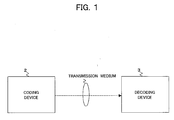
- FIG. 1 is a conceptual view of the communication system 1 of the present embodiment.
- the communication system 1 has a coding device 2 provided on a transmission side and a decoding device 3 provided on a reception side.
- the coding device 2 corresponds to the data processing apparatus and the coding device of the present invention.
- the coding device 2 on the transmission side generates frame image data (bit stream) compressed by a discrete cosine transform, Karhunen-Loewe transform, or other orthogonal transform and motion compensation, modulates the frame image data, then transmits the same via a satellite broadcast wave, cable TV network, telephone line network, cell phone line network, or other transmission medium.
- the decoding device 3 demodulates the received image signal, then generates and uses the frame image data decompressed by the inverse transform to the orthogonal transform at the time of modulation and the motion compensation.
- the transmission medium may be an optical disk, magnetic disk, semiconductor memory, or other storage medium as well.
- the decoding device 3 shown in FIG. 1 has the same configuration as that in the related art and performs decoding corresponding to the encoding of the coding device 2.
- FIG. 2 is a view of the overall configuration of the coding device 2 shown in FIG. 1.
- the coding device 2 has for example an analog/digital (A/D) conversion circuit 22, frame rearrangement circuit 23, computation circuit 24, orthogonal transform circuit 25, quantization circuit 26, reversible coding circuit 27, buffer 28, inverse quantization circuit 29, inverse orthogonal transform circuit 30, frame memory 31, rate control circuit 32, adder circuit 33, deblock filter 34, intra-prediction circuit 41, motion prediction and compensation circuit 43, and selection circuit 44.
- A/D analog/digital
- the A/D conversion circuit 22 converts an original image signal formed by an input analog luminance signal Y and color difference signals Pb and Pr to a digital image signal and outputs this to the frame rearrangement circuit 23.
- the frame rearrangement circuit 23 rearranges the frame image signal in the original image signal input from the A/D conversion circuit 22 to a sequence for encoding in accordance with a GOP (Group Of Pictures) structure composed of picture types I, P, and B to obtain the original image data S23 and outputs the same to the computation circuit 24, the motion prediction and compensation circuit 43, and the intra-prediction circuit 41.
- GOP Group Of Pictures
- the computation circuit 24 generates image data S24 indicating a difference between the original image data S23 and the predicted image data PI input from the selection circuit 44 and outputs this to the orthogonal transform circuit 25.
- the orthogonal transform circuit 25 applies a discrete cosine transform, Karhunen-Loewe transform, or other orthogonal transform to the image data S24 to generate the image data (for example, DCT coefficient) S25 and outputs this to the quantization circuit 26.
- the quantization circuit 26 quantizes the image data S25 with a quantization scale input from the rate control circuit 32 to generate the image data S26 (quantized DCT coefficient) and outputs this to the reversible coding circuit 27 and the inverse quantization circuit 29.
- the reversible coding circuit 27 encodes the image data S26 by variable length encoding or arithmetic encoding and stores the obtained image data in the buffer 28. At this time, the reversible coding circuit 27 stores a motion vector MV input from the motion prediction and compensation circuit 43 or the difference motion vector thereof, identification data of the reference image data, and the intra-prediction mode IPM input from the intra-prediction circuit 41 in the header data etc.
- the image data stored in the buffer 28 is modulated and then transmitted.
- the inverse quantization circuit 29 applies inverse quantization to the image data S26 and outputs the obtained data to the inverse orthogonal transform circuit 30.
- the inverse orthogonal transform circuit 30 applies an inverse transform to the orthogonal transform in the orthogonal transform circuit 25 to the data input from the inverse quantization circuit 29 and outputs the thus generated image data to the adder circuit 33.
- the adder circuit 33 adds the image data input (decoded) from the inverse orthogonal transform circuit 30 and the predicted image data PI input from the selection circuit 44 to generate recomposed image data and outputs this to the deblock filter 34.
- the deblock filter 34 eliminates block distortion of the recomposed image data input from the adder circuit 33 and writes the image data as the reference image data REF into the frame memory 31. Note that the frame memory 31 is sequentially written with the recomposed image data of pictures covered by the motion prediction and compensation processing by the motion prediction and compensation circuit 43 and the intra-prediction processing in the intra-prediction circuit 41 in units of macro blocks MB finished being processed.
- the rate control circuit 32 generates for example a quantization scale based on the image data read out from the buffer 28 and outputs this to the quantization circuit 26.
- the intra-prediction circuit 41 generates prediction image data PIi of macro blocks MB covered by processing for a plurality of prediction modes such as the intra 4x4 mode and intra 16x16 mode and generates indicator data COSTi serving as indicators of the code amounts of the encoded data based on these and the macro blocks MB covered by the processing in the original image data S23. Then, the intra-prediction circuit 41 selects the intra-prediction mode giving the smallest indicator data COSTi. The intra-prediction circuit 41 outputs the prediction image data PIi and the indicator data COSTi generated corresponding to the finally selected intra-prediction mode to the selection circuit 44.
- the intra-prediction circuit 41 When the intra-prediction circuit 41 receives as input a selection signal S44 indicating that the intra-prediction mode was selected, it outputs the prediction mode IPM indicating the finally selected intra-prediction mode to the reversible coding circuit 27. Note that even macro blocks MB belonging to the P slice or B slice are sometimes coded intra-prediction coding by the intra-prediction circuit 41.
- the intra-prediction circuit 41 generates for example the indicator data COSTi based on the following Equation (1).
- "i" is for example an identification number added to each block data of sizes corresponding to the intra-prediction modes forming the macro block MB covered by the processing.
- the "x” in the above Equation (1) is “1” in the case of the intra 16x16 mode and “16” in the case of the intra 4x4 mode.
- the intra-prediction circuit 41 calculates "SATD+header_cost (mode))" for all block data forming the macro block MB covered by the processing and adds them to calculate the indicator data COSTi.
- the "header_cost (mode)” is indicator data serving as the indicator of the code amount of the header data including the motion vector after the coding, the identification data of the reference image data, the selected mode, the quantization parameter (quantization scale), etc.
- the value of "header_cost (mode)” differs according to the prediction mode.
- "SATD” is indicator data serving as the indicator of the code amount of the difference image data between the block data in the macro block MB covered by the processing and previously determined block data (prediction block data) around the block data.
- the prediction image data PIi is defined according to one or more prediction block data.
- SATD is the data after applying a Hadamard transform (Tran) to the sum of the absolute differences between pixel data of block data Org covered by the processing and prediction block data Pre. Pixels in the block data are designated by s and t in the following Equation (2).
- the SAD shown in the following Equation (3) may be used in place of the SATD.
- another indicator representing distortion or residue such as the SSD defined in the MPEG4 and AVC may be used in place of SATD as well.
- the motion prediction and compensation circuit 43 When a macro block MB covered by the processing of the original image data S23 input from the frame rearrangement circuit 23 is inter-encoded, the motion prediction and compensation circuit 43 generates a motion vector MV and prediction image data of block data covered by the processing in units of block data defined by the motion prediction and compensation mode based on the reference image data REF encoded in the past and stored in the frame memory 31 for each of the plurality of motion prediction and compensation modes.
- the size of the block data and the reference image data REF are defined by for example the motion prediction and compensation mode.
- the motion prediction and compensation circuit 43 generates indicator data COSTm serving as the indicator of the code amount of the encoded data based on the macro block MB covered by the processing in the original image data S23 and the prediction block data (prediction image data PIm) thereof for each of the motion prediction and compensation modes. Then, the motion prediction and compensation circuit 43 selects the motion prediction and compensation mode giving the smallest indicator data COSTm. The motion prediction and compensation circuit 43 outputs the prediction image data PIm and the indicator data COSTm generated corresponding to the finally selected motion prediction and compensation mode to the selection circuit 44.
- the motion prediction and compensation circuit 43 outputs the motion vector generated corresponding to the finally selected motion prediction and compensation mode or the difference motion vector between the motion vector and the prediction motion vector to the reversible coding circuit 27. Still further, the motion prediction and compensation circuit 43 outputs a motion prediction and compensation mode MEM indicating the finally selected motion prediction and compensation mode to the reversible coding circuit 27. Finally, the motion prediction and compensation circuit 43 outputs the reference image data (reference frame) selected in the motion prediction and compensation processing to the reversible coding circuit 27.
- the motion prediction and compensation circuit 43 generates for example the indicator data COSTm based on the following Equation (4
- "i” is for example the identification number added to each block data of sizes of the motion prediction and compensation modes forming a macro block MB covered by the processing.
- the motion prediction and compensation circuit 43 calculates "(SATD+head_cost (mode))" for all block data forming the macro block MB covered by the processing and adds them to calculate the indicator data COSTm.
- the "head_cost(mode)” is indicator data serving as an indicator of the code amount of the header data including the motion vector after coding, identification data of the reference image data, selected mode, quantization parameter (quantization scale), etc.
- the value of "header_cost (mode)" differs according to the motion prediction and compensation mode.
- SATD is indicator data serving as the indicator of the code amount of the difference image data between the block data in a macro block MB covered by the processing and the block data in reference image data (reference block data) designated by the motion vector MB.
- the prediction image data PIm is defined by one or more reference block data.
- SATD is the data after applying a Hadamard transform (Tran) to the sum of the absolute differences between the pixel data of the block data Org covered by the processing and the reference block data (prediction image data) Pre.
- the pixels in the block data are designated according to s and t of the following Equation (5).
- SAD shown in the following Equation (6) of the first embodiment may be used as well.
- other indicator representing the distortion or residue such as SSD defined in MPEG4 and AVC may be used as well.
- the motion prediction and compensation circuit 43 is provided with various modes, for example, the inter base mode, Skip mode, and Direct mode, as the motion prediction and compensation mode.
- the inter base mode includes the inter 16x16 mode, inter 8x16 mode, inter 16x8 mode, inter 8x8 mode, inter 4x8 mode, and inter 4x4 mode.
- the sizes of the block data of them are 16x16, 8x16, 16x8, 8x8, 4x8, and 4x4.
- a forward prediction mode, a backward prediction mode, or a bi-directional prediction mode may be selected for the size of each of the inter base modes.
- the forward prediction mode is a mode using image data having a future display order as the reference image data
- the backward prediction mode is a mode using image data having a past display order as the reference image data
- the bi-directional prediction mode is a mode using image data having future and past display orders as the reference image data.
- a plurality of reference image data may be used in the motion prediction and compensation processing by the motion prediction and compensation circuit 43.
- the motion prediction and compensation circuit 43 encodes the motion vector or the difference motion vector thereof and the quantized difference image data constituted by the image data S26 in the reversible coding circuit 27 and includes them in the image data S2 in the inter base mode.
- the reversible coding circuit 27 of the coding device 2 does not encode any of the information of the image data S26 and the motion vector MV, that is, does not include it in the image data S2.
- the reversible coding circuit 27 includes the motion prediction and compensation mode selected by the motion prediction and compensation circuit 43 in the image data S2.
- the decoding device 3 generates a prediction motion vector based on the motion vectors of the block data around the block data covered by the processing when the motion prediction and compensation mode included in the image data S2 indicates the Skip mode and generates the decoded image data based on this prediction motion vector.
- the Skip mode does not encode either the image data S26 or the motion vector, so is able to remarkably reduce the coded data amount.
- the Skip mode may also be selected for the P pictures in addition to the B pictures.
- the reversible coding circuit 27 of the coding device 2 does not encode the motion vector MV.
- the reversible coding circuit 27 encodes the motion prediction and compensation mode and the image data S26.
- the decoding device 3 When the motion prediction and compensation mode included in the image data S2 indicates the Direct mode, the decoding device 3 generates a prediction motion vector based on the motion vectors of the block data around the block data covered by the processing and generates decoded image data based on this prediction motion vector and the encoded image data S26.
- the Direct mode does not encode the motion vector, therefore can reduce the coded data amount.
- the Skip mode may be selected for the B pictures.
- the Direct mode includes the 16x16 Direct mode using a block size of 16x16 and the 8x8 Direct mode using a block size of 8x8. Further, each of the 16x16 Direct mode and the 8x8 Direct mode includes a Spatial Direct mode and a Temporal Direct mode.
- the motion prediction and compensation circuit 43 generates a prediction motion vector (motion vector) by using the motion vectors of the block data around the block data covered by the processing in the case of the Spatial Direct mode. Then, the motion prediction and compensation circuit 43 specifies the reference block data based on the prediction motion vector and generates the reference image data PIm.
- the motion prediction and compensation circuit 43 generates the prediction motion vector (motion vector) by using the motion vector of the block data at a corresponding location in the reference image data of the block data covered by the processing in the case of the Temporal Direct mode.
- the motion prediction and compensation circuit 43 specifies the reference block data based on the prediction motion vector and generates the reference image data PIm.
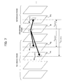
- the decoding device 3 calculates motion vectors MV 0 and MV 1 according to the following Equations (7) and (8) when the Temporal Direct mode is designated, for example, the block data covered by the processing in the frame data B uses frame data RL 0 and RL 1 as the reference image data, and the motion vector with respect to the frame data RL 0 of the block data at the corresponding location in the frame data RL 1 is MVc as shown in FIG. 3.
- TD D indicates an interval of the display timing between the reference image data RL 0 and the reference image data RL 1
- TD B indicates the interval of the display timing between the frame data B and the reference image data RL 0 .
- FIG. 4 shows an example of the hardware configuration of the motion prediction and compensation circuit 43.
- the motion prediction and compensation circuit 43 has for example an interface 51, a memory 52, and a processing circuit 53 all connected via a data line 50.
- the interface 51 performs the input/output of data with the frame rearrangement circuit 23, the reversible coding circuit 27, and the frame memory 31.
- the memory 52 stores the program PRG1 and various data used for the processing of the processing circuit 53.
- the processing circuit 53 centrally controls the processing of the motion prediction and compensation circuit 43 according to the program PRG1 read out from the memory 52.
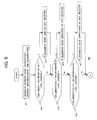
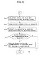
- FIG. 5 and FIG. 6 are flow charts for explaining the example of the operation of the motion prediction and compensation circuit 43.
- the motion prediction and compensation circuit 43 performs the following processing for the block data covered by the processing in the original image data S23.
- the motion prediction and compensation circuit 43 generates the motion vectors MV (inter 16x16), MV (inter 8x8), MV (Skip), MV (Direct16x16), and MV (Direct8x8) of the block data covered by the processing in the above-explained sequence for each of the inter 16x16, inter 8x8, Skip, Direct16x16, and Direct8x8.
- the motion prediction and compensation circuit 43 judges whether or not the absolute value of the difference vector between a motion vector MV (skip) and a motion vector MV (inter 16x16) generated at step ST1 is larger than a previously determined standard value MV_RANGE, proceeds to step ST3 when judging that the absolute value is larger than the standard value, and proceeds to step ST4 when not judging so.
- the motion prediction and compensation circuit 43 determines that the Skip mode is not selected in the selection processing of the motion prediction and compensation mode explained later.
- the motion prediction and compensation circuit 43 judges whether or not the absolute value of the difference vector between a motion vector MV (Direct8x8) and a motion vector MV (inter 8x8) generated at step ST1 is larger than the previously determined standard value MV_RANGE, proceeds to step ST5 when judging that the absolute value is larger than the standard value, and proceeds to step ST6 when not judging so.
- the motion prediction and compensation circuit 43 determines that the Direct8x8 mode is not selected in the selection processing of the motion prediction and compensation mode explained later.
- the motion prediction and compensation circuit 43 judges whether or not the absolute value of a difference vector between the motion vector MV (Direct16x16) and the motion vector MV (inter 16x16) generated at step ST1 is larger than a previously determined standard value MV_RANGE, proceeds to step ST7 when judging that the absolute value is larger than the standard value, and proceeds to step ST8 when not judging so.
- the motion prediction and compensation circuit 43 determines that the Direct16x16 mode is not selected in the selection processing of the motion prediction and compensation mode explained later.
- the motion prediction and compensation circuit 43 calculates the indicator data COSTm by the above routines for the motion prediction and compensation mode not designated as not selected by steps ST3, ST5, and ST7.
- the motion prediction and compensation circuit 43 selects the motion prediction and compensation mode giving the smallest indicator mode COSTm calculated at step ST8.
- the motion prediction and compensation circuit 43 outputs the prediction image data PIm and the indicator data COSTm generated corresponding to the selected motion prediction and compensation mode to the selection circuit 44.
- the motion prediction and compensation circuit 43 judges whether or not a selection signal S44 indicating that the motion prediction and compensation mode was selected was input from the selection circuit 44 at a predetermined timing, proceeds to step ST12 when judging that it was input, and terminates the processing when not judging so.
- the motion prediction and compensation circuit 43 outputs a motion vector MV generated corresponding to the motion prediction and compensation mode selected at step ST9, or a difference motion vector thereof, and the selected motion prediction and compensation mode MEM to the reversible coding circuit 27.
- the selection circuit 44 specifies a smaller indicator data between the indicator data COSTm input from the motion prediction and compensation circuit 43 and the indicator data COSTi input from the intra-prediction circuit 41 and outputs the prediction image data PIm or PIi input corresponding to the specified indicator data to the computation circuit 24 and the adder circuit 33. Further, the selection circuit 44 outputs a selection signal S44 indicating that the motion prediction and compensation mode was selected to the motion prediction and compensation circuit 43 when the indicator data COSTm is smaller. On the other hand, the selection circuit 44 outputs the selection signal S44 indicating that the intra-prediction mode was selected to the motion prediction and compensation circuit 43 when the indicator data COSTi is smaller. Note that, in the present embodiment, it is also possible if the intra-prediction circuit 41 and the motion prediction and compensation circuit 43 output all generated indicator data COSTi and COSTm to the selection circuit 44, and the smallest indicator data is specified in the selection circuit 44.
- the image signal which becomes the input is first converted to a digital signal at the A/D conversion circuit 22.
- the frame image data is rearranged in the frame rearrangement circuit 23 in accordance with the GOP structure of the image compression information which becomes the output.
- the original image data S23 obtained by that is output to the computation circuit 24, the motion prediction and compensation circuit 43, and the intra-prediction circuit 41.
- the computation circuit 24 detects the difference between the original image data S23 from the frame rearrangement circuit 23 and the prediction image data PI from the selection circuit 44 and outputs the image data S24 indicating the difference to the orthogonal transform circuit 25.
- the orthogonal transform circuit 25 applies a discrete cosine transform, Karhunen-Loewe transform, or other orthogonal transform to the image data S24 to generate the image data (DCT coefficient) S25 and outputs this to the quantization circuit 26.
- the quantization circuit 26 quantizes the image data S25 and outputs the image data (quantized DCT coefficient) S26 to the reversible coding circuit 27 and the inverse quantization circuit 29.
- the reversible coding circuit 27 applies reversible coding such as variable length coding or arithmetic coding to the image data S26 to generate the image data S28 and stores this in the buffer 28.
- the rate control circuit 32 controls the quantization rate in the quantization circuit 26 based on the image data S28 read out from the buffer 28.
- the inverse quantization circuit 29 inversely quantizes the image data S26 input from the quantization circuit 26 and outputs the result to the inverse orthogonal transform circuit 30. Then, the inverse orthogonal transform circuit 30 outputs the image data generated by performing the inverse transform processing of the orthogonal transform circuit 25 to the adder circuit 33.
- the adder circuit 33 adds the image data from the inverse orthogonal transform circuit 30 and the prediction image data PI from the selection circuit 44 to generate the recomposed image data and outputs this to the deblock filter 34. Then, the deblock filter 34 eliminates the block distortion of the recomposed image data and writes the generated image data as the reference image data into the frame memory 31.
- the intra-prediction circuit 41 performs the intra-prediction processing explained above and outputs the prediction image data PIi as the result of this and the indicator data COSTi to the selection circuit 44. Further, the motion prediction and compensation circuit 43 performs the motion prediction and compensation processing explained by using FIG. 5 and FIG. 6 and outputs the prediction image data PIm as the result of this and the indicator data COSTm to the selection circuit 44. Then, the selection circuit 44 specifies the smaller indicator data between the indicator data COSTm input from the motion prediction and compensation circuit 43 and the indicator data COSTi input from the intra-prediction circuit 41 and outputs the prediction image data PIm or PIi input corresponding to the specified indicator data to the computation circuit 24 and the adder circuit 33.
- the coding device 2 designates the motion prediction and compensation modes as not selected in the case where the motion vectors MV of Skip, Direct16x16, and Direct8x8 among the motion prediction and compensation modes are more than the motion vector MV of the inter base mode and predetermined standard value as explained by using FIG. 5 and FIG. 6. For this reason, in the processing of step ST9 shown in FIG. 6, it is possible to avoid the selection of these motion prediction and compensation modes.
- the coding device 2 forcibly selects the inter base mode when the motion vectors MV of the Skip, Direct16x16, and Direct8x8 modes greatly deviate from the original motion vector even when the indicator data COSTm is smaller, encodes the motion vectors or difference motion vectors thereof and the image data S26 as the quantized difference image data at the reversible coding circuit 27, and includes the same in the image data S2.
- the present embodiment is an embodiment corresponding to the fourth to sixth invention.
- the generating means of the fourth invention is realized by a processing circuit 63 of an intra-prediction circuit 41a shown in FIG. 9 calculating indicator data SATDa based on Equation (12) explained later at step ST22 shown in FIG. 10.
- the selecting means of the fourth invention is realized by calculating indicator data COSTai based on Equation (11) explained later at step ST22 shown in FIG. 10 and executing step ST24 by the processing circuit 63.
- the processing of calculating the indicator data SATD (first indicator data) by the intra-prediction circuit 41a corresponds to the first routine of the fifth invention or the first process of the sixth invention.
- the processing of specifying Max4x4 by the intra-prediction circuit 41a corresponds to the second routine of the fifth invention or the second process of the sixth invention.
- the processing of calculating the indicator data SATDa (second indicator data) based on Equation (12) explained later by the intra-prediction circuit 41a corresponds to the third routine of the fifth invention or the third process of the sixth invention.
- the processing of calculating the indicator data COSTai (third indicator data) based on Equation (11) explained later and performing step ST24 shown in FIG. 10 by the intra-prediction circuit 41a corresponds to the fourth routine of the fifth invention or the fourth process of the sixth invention.
- the block data of the present embodiment corresponds to the block data of the present invention.
- the generating means of the fourth invention is realized by a processing circuit 83 of a motion prediction and compensation circuit 43a shown in FIG. 13 calculating the indicator data SATDa based on Equation (15) explained later at step ST42 shown in FIG. 14.
- the selecting means of the fourth invention is realized by calculating the indicator data COSTam based on Equation (14) explained later at step ST22 shown in FIG. 14 and executing step ST44 by the processing circuit 83.
- the processing of calculating the indicator data SATD (first indicator data) by the motion prediction and compensation circuit 43a corresponds to the first routine of the fifth invention or the first process of the sixth invention.
- the processing of specifying Max4x4 by the motion prediction and compensation circuit 43a corresponds to the second routine of the fifth invention or the second process of the sixth invention.
- the processing of calculating the indicator data SATDa (second indicator data) based on Equation (15) explained later by the motion prediction and compensation circuit43a corresponds to the third routine of the fifth invention or the third process of the sixth invention.
- the processing of calculating the indicator data COSTam (third indicator data) based on Equation (14) explained later and performing step ST44 shown in FIG. 14 by the motion prediction and compensation circuit 43a corresponds to the fourth routine of the fifth invention or the fourth process of the sixth invention.
- Each of the programs PRG2 and PRG3 of the present embodiment corresponds to the program of the fifth invention.
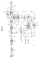
- FIG. 8 is an overall view of the configuration of a coding device 2a according to the embodiment of the present invention.
- the coding device 2a has for example an A/D conversion circuit 22, frame rearrangement circuit 23, computation circuit 24, orthogonal transform circuit 25, quantization circuit 26, reversible coding circuit 27, buffer 28, inverse quantization circuit 29, inverse orthogonal transform circuit 30, frame memory 31, rate control circuit 32, adder circuit 33, deblock filter 34, intra-prediction circuit 41a, motion prediction and compensation circuit 43a, and selection circuit 44.
- FIG. 7 components given the same notations as those of FIG. 2 are the same as those explained in the first embodiment.
- the coding device 2a of the present embodiment is characterized in the intra-prediction circuit 41a and the motion prediction and compensation circuit 43a.
- the intra-prediction circuit 41a generates the prediction image data PIi of the macro block MB covered by the processing for each of a plurality of prediction modes, for example intra 4x4 mode and intra 16x16 mode, and generates the indicator data COSTai serving as the indicator of the code amount of the encoded data based on this and the macro block MB covered by the processing in the original image data S23. Then, the intra-prediction circuit 41a selects the intra-prediction mode giving the smallest indicator data COSTai. The intra-prediction circuit 41a outputs the prediction image data PIi generated corresponding to the finally selected intra-prediction mode and the indicator data COSTai to the selection circuit 44.
- a plurality of prediction modes for example intra 4x4 mode and intra 16x16 mode
- the intra-prediction circuit 41a When receiving as input the selection signal S44 indicating that the intra-prediction mode was selected, the intra-prediction circuit 41a outputs the prediction mode IMP indicating the finally selected intra-prediction mode to the reversible coding circuit 27. Note sometimes the intra-prediction coding by the intra-prediction circuit 41a is carried out even for the macro block MB belonging to the P slice or the B slice.
- the intra-prediction circuit 41a generates for example the indicator data COSTai based on the following Equation (11).
- the intra-prediction circuit 41a calculates "SATDa+header_cost (mode))" for all block data forming the macro block MB covered by the processing and adds them to calculates the indicator data COSTai.
- the "header_cost (mode)” is indicator data serving as an indicator of the code amount of the header data including the selected intra-prediction mode, the quantization parameter (quantization scale), etc. and indicates a different value according to the intra-prediction mode.
- SATDa is indicator data serving as an indicator of the code amount of the difference image data between the block data in the macro block MB covered by the processing and previously determined block data (prediction block data) around the block data.
- the prediction image data PIi is defined by one or more prediction block data.
- the present embodiment is characterized in the method of calculation of SATDa.
- the intra-prediction circuit 41a performs the computation of the above Equation (5) in units of 4x4 pixel data for block data comprised of 16x16 pixel data and adds the results to calculate SATD.
- SATD is for example the data after applying a Hadamard transform to the sum of the absolute differences between the pixel data of the block data Org covered by the processing and the prediction image data (reference block data) Pre.
- the intra-prediction circuit 41a specifies the maximum value among the-computation results of Equation (5) performed for each 4x4 pixel data in the block data and defines that as Max4x4.
- the intra-prediction circuit 41a adds "Max4x4*16" to SATD and divides the result by 2 to calculate the indicator data SATDa.
- the intra-prediction circuit 41a is able to calculate the indicator data SATDa in which the influence of Max4x4 (maximum value of the difference) is reflected more strongly in comparison with the case where only SATD is used.
- the SAD shown in Equation (3) of the first embodiment may be used as well.
- another indicator representing distortion or residue such as SSD defined in MPEG4 and AVC may be used as well.
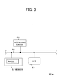
- FIG. 9 shows an example of the hardware configuration of the intra-prediction circuit 41a shown in FIG. 8.
- the intra-prediction circuit 41a has for example an interface 61, a memory 62, and a processing circuit 63 all connected via a data line 60.
- the interface 61 performs the input/output of data with the frame rearrangement circuit 23, the reversible coding circuit 27, and the frame memory 31.
- the memory 62 stores the program PRG2 and various data used for processing of the processing circuit 63.
- the processing circuit 63 centrally controls the processing of the intra-prediction circuit 41a according to the program PRG2 read out from the memory 62.
- FIG. 10 is a flow chart for explaining the example of the operation of the intra-prediction circuit 41a.
- the intra-prediction circuit 41a performs the following processing for the block data covered by the processing in the original image data S23.
- the intra-prediction circuit 41a specifies a not yet processed intra-prediction mode among the plurality of intra-prediction modes including the intra 16x16 mode and intra 4x4 mode.
- the intra-prediction circuit 41a calculates the indicator data COSTai by the means explained by using the above Equation (12) for the intra-prediction mode specified at step ST21.
- the intra-prediction circuit 41a judges whether or not the processing of step ST22 has ended for all intra-prediction modes, proceeds to step ST24 when judging the end, and returns to step ST21 when not judging so.
- the intra-prediction circuit 41a selects the smallest intra-prediction mode among indicator data COSTai calculated at step ST22 for all intra-prediction modes.
- the intra-prediction circuit 41a outputs the prediction image data PIi and the indicator data COSTai generated corresponding to the intra-prediction mode selected at step ST24 to the selection circuit 44.
- the intra-prediction circuit 41a judges whether or not the selection signal S44 indicating that the intra-prediction mode was selected was input from the selection circuit 44 at the predetermined timing, proceeds to step ST27 when judging that the selection signal S44 was input, and ends the processing when not judging so.
- the intra-prediction circuit 41a outputs the intra-prediction mode IPM selected at step S24 to the reversible coding circuit 27.
- the intra-prediction circuit 41a is provided with for example a SATD calculation circuit 71, a maximum value specifying circuit 72, a COST calculation circuit 73, and a mode judgment circuit 74 as shown in FIG. 11 in place of the configuration shown in FIG. 9.
- the SATD calculation circuit 71 performs the computation of the above Equation (5) and adds the results to calculate SATD.
- the maximum value specifying circuit 72 specifies the maximum value among the computation results of Equation (5) performed for each 4x4 pixel data in the block data and defines that as Max4x4.
- the COST calculation circuit 73 adds "Max4x4*16" to SATD and divides the result by 2 to calculate the indicator data SATDa.
- the mode judgment circuit 74 performs the processing of step ST24 shown in FIG. 10.
- the motion prediction and compensation circuit 43a generates the motion vectors MV of the block data covered by the processing and the prediction image data in units of the block data defined by the motion prediction and compensation mode based on the reference image data encoded in the past and stored in the frame memory 31 for each of a plurality of motion prediction and compensation modes in the case where the macro block MB covered by the processing of the original image data S23 input from the frame rearrangement circuit 23 is inter-coded.
- the size of the block data and the reference image data REF are defined by for example the motion prediction and compensation mode.
- the motion prediction and compensation circuit 43a generates the indicator data COSTam serving as the indicator of the code amount of the encoded data based on the macro block MB covered by the processing in the original image data S23 and the prediction block data (prediction image data PIm) thereof for each of the motion prediction and compensation modes. Then, the motion prediction and compensation circuit 43a selects the motion prediction and compensation mode giving the smallest indicator data COSTam. The motion prediction and compensation circuit 43a outputs the prediction image data PIm generated corresponding to the finally selected motion prediction and compensation mode and the indicator data COSTma to the selection circuit 44.
- the motion prediction and compensation circuit 43a outputs the motion vector generated corresponding to the finally selected motion prediction and compensation mode or the difference motion vector between the motion vector and the prediction motion vector to the reversible coding circuit 27.
- the motion prediction and compensation circuit 43a outputs the finally selected motion prediction and compensation mode MEM to the reversible coding circuit 27.
- the motion prediction and compensation circuit 43a outputs the identification data of the reference image data (reference frame) selected in the motion prediction and compensation processing to the reversible coding circuit 27.
- i is for example an identification number added to each of the block data of sizes corresponding to the motion prediction and compensation modes forming the macro block MB covered by the processing.
- the motion prediction and compensation circuit 43a calculates "SATDa+header cost (mode))" for all block data forming the macro block MB covered by the processing and adds them to calculate the indicator data COSTam.
- the "header_cost (mode)” is indicator data serving as an indicator of the code amount of the header data including the motion vector or the difference motion vector thereof, the identification data of the reference image data, the selected motion prediction and compensation mode, the quantization parameter (quantization scale), etc. and indicates a different value according to the motion prediction and compensation mode.
- SATDa is indicator data serving as an indicator of the code amount of the difference image data between the block data in the macro block MB covered by the processing and previously determined block data (prediction block data) around the block data.
- the prediction image data PIi is defined by one or more prediction block data.
- the present embodiment is characterized by the method of calculation of SATDa.
- the motion prediction and compensation circuit 43a calculates the indicator data SATDa for the inter 16x16 mode, intra 16x16 mode, intra 4x4 mode, Skip mode, and Direct16x16 mode explained in the first embodiment as shown in FIG. 12(A) and the following Equation (14).
- SATDa SATD + Max ⁇ 4 ⁇ 4 * 16 / 2
- the "SATD" in the above Equation (14) is the same as in Equation (5) explained in the first embodiment.
- the motion prediction and compensation circuit 43a performs the computation of the above Equation (5) in units of 4x4 pixel data for the block data comprised by 16x16 pixel data and adds the results to calculate SATD.
- SATD is for example the data after applying a Hadamard transform to the sum of the absolute differences between the pixel data of the block data Org covered by the processing and the prediction image data (reference block data) Pre.
- the motion prediction and compensation circuit 43a specifies the maximum value among the computation results of Equation (5) performed for each 4x4 pixel data in the block data and defines that as Max4x4.
- the motion prediction and compensation circuit 43a adds "Max4x4*16" to SATD and divides the result by 2 to calculate the indicator data SATDa.
- the motion prediction and compensation circuit 43a is able to calculate indicator data SATDa in which the influence of Max4x4 (maximum value of the difference) is reflected more strongly in comparison with the case where only SATD is use
- SATD is for example the data after applying a Hadamard transform to the sum of the absolute differences between the pixel data of the block data Org covered by the processing and the prediction image data (reference block data) Pre.
- the motion prediction and compensation circuit 43a specifies the maximum value among the computation results of Equation (5) performed for each 4x4 pixel data in the block data, and defines that as Max4x4.
- the motion prediction and compensation circuit 43a adds "Max4x4*8" to SATD and divides the result by 2 to calculate the indicator data SATDa.
- the motion prediction and compensation circuit 43a is able to calculate indicator data SATDa in which the influence of Max4x4 (maximum value of the difference) is reflected more strongly in comparison with the case where only SATD is used.
- SATD is for example the data after applying a Hadamard transform to the sum of the absolute differences between the pixel data of the block data Org covered by the processing and the prediction image data (reference block data) Pre.
- the motion prediction and compensation circuit 43a specifies the maximum value among the computation results of Equation (5) performed for each 4x4 pixel data in the block data and defines that as Max4x4.
- the motion prediction and compensation circuit 43a adds "Max4x4*4" to SATD and divides the result by 2 to calculate the indicator data SATDa.
- the motion prediction and compensation circuit 43a is able to calculate indicator data SATDa in which the influence of Max4x4 (maximum value of the difference) is reflected more strongly in comparison with the case where only SATD is used.
- SATD is for example the data after applying a Hadamard transform to the sum of the absolute differences between the pixel data of the block data Org covered by the processing and the prediction image data (reference block data) Pre.
- the motion prediction and compensation circuit 43a specifies the maximum value among the computation results of Equation (5) performed for each 4x4 pixel data in the block data and defines that as Max4x4.
- the motion prediction and compensation circuit 43a adds "Max4x4*2" to SATD and divides the result by 2 to calculate the indicator data SATDa.
- the motion prediction and compensation circuit 43a is able to calculate indicator data SATDa in which the influence of Max4x4 (maximum value of the difference) is reflected more strongly in comparison with the case where only SATD is used.
- the motion prediction and compensation circuit 43a calculates the indicator data SATDa for the inter 4x4 mode as shown in FIG. 12(E) and the following Equation (18).
- SATD is for example the data after applying a Hadamard transform to the sum of the absolute differences between the pixel data of the block data Org covered by the processing and the prediction image data (reference block data) Pre.
- the motion prediction and compensation circuit 43a specifies the maximum value among the computation results of Equation (5) performed for each 4x4 pixel data in the block data and defines that as Max4x4.
- the motion prediction and compensation circuit 43a adds "Max4x4*4" to SATD and divides the result by 2 to calculate the indicator data SATDa.
- the motion prediction and compensation circuit 43a is able to calculate the indicator data SATDa in which the influence of Max4x4 (maximum value of the difference) is reflected more strongly in comparison with the case where only SATD is used.
- SAD shown in Equation (3) of the first embodiment may be used as well.
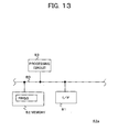
- FIG. 13 is an example of the hardware configuration of the motion prediction and compensation circuit 43a shown in FIG. 8.
- the motion prediction and compensation circuit 43a has for example an interface 81, a memory 82, and a processing circuit 83 all connected via a data line 80.
- the interface 81 performs the input/output of data with the frame rearrangement circuit 23, the reversible coding circuit 27, and the frame memory 31.
- the memory 82 stores the program PRG3 and various data used for processing of the processing circuit 83.
- the processing circuit 83 centrally controls the processing of the motion prediction and compensation circuit 43a according to the program PRG3 read out from the memory 82.
- FIG. 14 is a flow chart for explaining the example of the operation of the motion prediction and compensation circuit 43a.
- the motion prediction and compensation circuit 43a performs the following processing for the block data covered by the processing in the original image data S23.
- the motion prediction and compensation circuit 43a specifies a not yet processed motion prediction and compensation mode among a plurality of motion prediction and compensation modes including the inter 16x16 mode, Skip mode, Direct16x16 mode, inter 8x16 mode, inter 16x8 mode, inter 8x8 mode, Direct8x8 mode, inter 4x8 mode, inter 8x4 mode, and inter 4x4 mode.
- the motion prediction and compensation circuit 43a calculates the indicator data COSTam by the above-explained means for the motion prediction and compensation mode specified at step ST41.
- the motion prediction and compensation circuit 43a judges whether or not the processing of step ST42 was ended for all motion prediction and compensation modes, proceeds to step ST44 when judging the end, and returns to step T41 when not judging so.
- the motion prediction and compensation circuit 43a selects the smallest motion prediction and compensation mode among the indicator data COSTam calculated at step ST42 for all motion prediction and compensation modes.
- the motion prediction and compensation circuit 43a outputs the prediction image data PImi generated corresponding to the motion prediction and compensation mode selected at step ST44 and the indicator data COSTam to the selection circuit 44.
- the motion prediction and compensation circuit 43a judges whether or not the selection signal S44 indicating that the motion prediction and compensation mode was selected was input from the selection circuit 44 at the predetermined timing, proceeds to step ST47 when judging the input, and ends the processing when not judging so.
- the motion prediction and compensation circuit 43a outputs the motion prediction and compensation mode MPM selected at step ST44, the motion vector MV, and the identification data of the reference image data to the reversible coding circuit 27.
- the motion prediction and compensation circuit 43a is provided with for example a SATD calculation circuit 91, a maximum value specifying circuit 92, a COST calculation circuit 93, and a mode judgment circuit 94 as shown in FIG. 15 in place of the configuration shown in FIG. 13.
- the SATD calculation circuit 91 performs the computation of the above Equation (5) and adds the results to calculates SATD.
- the maximum value specifying circuit 92 specifies the maximum value among computation results of Equation (5) performed for each 4x4 pixel data in the block data and defines that as Max4x4.
- the COST calculation circuit 93 calculates the indicator data SATDa by using SATD as explained above.
- the mode judgment circuit 74 performs the processing of step ST44 shown in FIG. 14.
- the example of the overall operation of the coding device 2a is the same as that of the coding device 2 of the first embodiment except the intra-prediction circuit 41a and the motion prediction and compensation circuit 43 perform the above-explained operation. Note that in the present embodiment as well, it is also possible even if all indicator data COSTai and COSTam generated by the intra-prediction circuit 41a and the motion prediction and compensation circuit 43a are output to the selection circuit 44, and the selection circuit 44 specifies the smallest indicator data.
- the coding device 2a uses the indicator data STDAa in which the influence of Max4x4 (maximum value of the difference) is reflected strongly more than the case where only the SATD is used in the mode selection of the intra-prediction circuit 41a and the motion prediction and compensation circuit 43a.
- the intra-prediction circuit 41a and the motion prediction and compensation circuit 43a calculate the indicator data SATDa as shown in FIG. 16 and the following Equations (19) to (23).
- a, b, c, d, e, f, g, h, i, and j are predetermined coefficients.
- the coefficients a, c, e, g, and i correspond to the first coefficient of the fourth invention
- the coefficients b, d, f, h, and j correspond to the second coefficient of the fourth invention.
- the intra-prediction circuit 41a and the motion prediction and compensation circuit 43a calculate the indicator data SATDa based on FIG. 16(B) and the following Equation (20) in the intra 16x16 mode, intra 4x4 mode, Skip mode, and Direct16x16 mode.
- Equation 20 SATDa c * SATD + d * Max ⁇ 4 ⁇ 4 * 16 / c + d
- the coefficients a, b, c, d, e, f, g, h, i and j from the outside and possible to freely set the weights of SATD and Max4x4.
- the present invention is not limited to the above-explained embodiments.
- the present invention may use modes other than the intra-prediction mode and the motion prediction and compensation mode explained above.
- the invention can be applied to a system for coding image data.
Landscapes
- Engineering & Computer Science (AREA)
- Multimedia (AREA)
- Signal Processing (AREA)
- Compression Or Coding Systems Of Tv Signals (AREA)
Abstract
Motion prediction and compensation circuit does not select Skip mode and Direct mode in motion prediction and compensation mode when a difference between prediction motion vector and actual motion vector exceed predetermined standard.
Description
- The present invention relates to an image processing apparatus used for encoding image data, a program for the same, and a method of the same.
- In recent years, apparatuses based on a method such as a MPEG (Moving Picture Experts Group) which handles image data as digital data and, at that time, for the purpose of transmitting and storing information with a high efficiency, compressed the image data by using a discrete cosine transform or other orthogonal transform and motion compensation utilizing the redundancy peculiar to image information, have been spreading in both distribution of information by broadcast stations etc. and reception of information at general homes.
- A coding system (method) called the "AVC/h.264" is being proposed as a successor to the MPEG-2 and MPEG-4 systems (methods).
The AVC/h.264 system defines a plurality of modes for encoding for each of an intra-prediction mode and a motion prediction and compensation mode and selects the mode having the smallest code amount (the highest coding efficiency) based on the characteristics of the image data. - By the way, the above motion prediction and compensation mode includes a "direct" mode and a "skip" mode performing prediction based on the motion vectors of block data around block data to be processed and thereby not encoding any motion vectors.
However, sometimes even when the predicted motion vector is very different from the original motion vector, the Direct mode or the Skip mode gives the smallest code amount and therefore is selected. In such a case, jerky motion occurs in the decoded image due to the difference of motion vectors and becomes a cause of deterioration of the image quality. - Further, if the mode is selected in units of macro blocks based on only the code amounts of entire macro blocks, if the code amount of a small part of the blocks in a macro block is large and the code amount of the far greater rest of the blocks is small, the code amount of the entire macro block will become small and a mode unsuitable from the viewpoint of the image quality will end up being selected for the encoding of the small part of the blocks.
- It is therefore desirable to provide an image processing apparatus able to realize encoding giving a higher image quality in comparison with the past, a program for the same, and a method of the same.
- To achieve the above objects, an image processing apparatus of a first invention, used for generating a motion vector of block data of a block covered by processing among a plurality of blocks defined in a two-dimensional image region and encoding the motion vector and a difference between prediction block data generated based on the motion vector and the block data covered by the processing, includes a judging means for judging whether or not the difference between motion vectors generated for each of a first mode of predicting the motion vector of the block data covered by the processing from the motion vector of other block data and not encoding the predicted motion vector and a second mode of generating the motion vector of the block data covered by the processing based on the difference between the block data covered by the processing and the block data in a reference image data and encoding the motion vector and difference image data between the block data covered by the processing and the reference block data corresponding to the generated motion vector in the reference image data exceeds a predetermined standard; and a selecting means for selecting the second mode when the judging means judges that the difference exceeds the predetermined standard and selecting a mode between the first mode and the second mode in which the code amount by the encoding becomes the minimum when the judging means judges that the difference does not exceed the predetermined standard.
- The mode of operation of the image processing apparatus of the first invention is as follows.
First, the judging means generates the motion vector of block data covered by the processing based on the first mode of predicting the motion vector of the block data covered by the processing from the motion vector of other block data and not encoding the predicted motion vector and the difference between the block data covered by the processing and the block data in the reference image data.
Then, the judging means judges whether or not the difference between the above generated motion vector and the motion vector generated for the second mode of encoding the difference image data between the block data covered by the processing and the reference block data corresponding to the above generated motion vector in the reference image data exceeds a predetermined standard.
Next, the selecting means selects the second mode when the judging means judges that the difference exceeds the predetermined standard and selects the mode between the first mode and the second mode in which the code amount by the encoding becomes the minimum when the judging means judges that the difference does not exceed the predetermined standard. - A program, a second present invention for making a computer execute processing for generating a motion vector of block data of a block covered by the processing among a plurality of blocks defined in a two dimensional image region and encoding the motion vector and a difference between prediction block data generated based on the motion vector and the block data covered by the processing, includes a first routine of generating the motion vector for each of a first mode of predicting the motion vector of the block data covered by the processing from the motion vector of the other block data and not encoding the predicted motion vector and a second mode of generating the motion vector of the block data covered by the processing based on the difference between the block data covered by the processing and the block data in a reference image data and encoding the motion vector and a difference image data between the block data covered by the processing and the reference block data corresponding to the generated motion vector in the reference image data; a second routine of judging whether or not the difference between the motion vector of the first mode generated in the first routine and the motion vector of the second mode exceeds a predetermined standard; and a third routine of selecting the second mode when judging that the difference exceeds the predetermined standard in the second routine and selecting the mode between the first mode and the second mode in which the code amount by the encoding becomes the minimum when judging that the difference does not exceed the predetermined standard.
- The mode of operation of the program of the second invention is as follows.
First, the computer executes the program.
Then, the computer generates the Motion vector according to the first routine of the program for each of a first mode of predicting the motion vector of the block data covered by the processing from the motion vector of the other block data and not encoding the predicted motion vector and a second mode of generating the motion vector of the block data covered by the processing based on the difference between the block data covered by the processing and the block data in a reference image data and encoding the motion vector and a difference image data between the block data covered by the processing and the reference block data corresponding to the generated motion vector in the reference image data.
Next, the computer judges whether or not the difference between the motion vector of the first mode generated in the first routine and the motion vector of the second mode generated in the first routine exceeds the predetermined standard according to the second routine of the program.
Next, according to the third routine, the computer selects the second mode when judging that the difference exceeds the predetermined standard in the second routine and selects the mode between the first mode and the second mode in which the code amount by the encoding becomes the minimum when judging that the difference does not exceed the predetermined standard. - An image processing method of a third present invention includes: having a computer executes processing for generating a motion vector of block data of a block covered by processing among a plurality of blocks defined in a two-dimensional image region and encoding the motion vector and a difference between prediction block data generated based on the motion vector and the block data covered by the processing, a first process of generating the motion vector for each of a first mode of predicting the motion vector of the block data covered by the processing from the motion vector of other block data and not encoding the predicted motion vector and a second mode of generating the motion vector of the block data covered by the processing based on the difference between the block data covered by the processing and the block data in a reference image data and encoding the motion vector and difference image data between the block data covered by the processing and the reference block data corresponding to the generated motion vector in the reference image data, a second process of judging whether or not the difference between the motion vector of the first mode generated in the first process and the motion vector of the second mode exceeds a predetermined standard, and a third process of selecting the second mode when judging that the difference exceeds the predetermined standard in the second process and selecting the mode between the first mode and the second mode in which the code amount by the encoding becomes the minimum when judging that the difference does not exceed the predetermined standard.
- An image processing apparatus of a fourth present invention used for encoding block data of a block covered by processing among one or more blocks forming a macro block defined in a two-dimensional image region based on that block data and prediction block data of the block data, includes: a generating means for generating first indicator data in accordance with a difference between one or more unit block data forming the block data covered by the processing and unit block data in prediction block data corresponding to this unit block data in units of the unit block data, specifying first indicator data indicating the maximum data among the first indicator data, and generating second indicator data in which the specified first indicator data is strongly reflected as a value in comparison with a sum of the first indicator data generated for the unit block data forming the block data covered by the processing based on the first indicator data; and a selecting means for selecting the mode giving the smallest third indicator data in accordance with the sum of the second indicator data generated by the generating means for the one or more block data forming a macro block covered by the processing among a plurality of modes in which at least one of the size of the block data defined for the macro block covered by the processing, existence of encoding of the motion vector, and existence of encoding of the difference are different from each other.
- The mode of operation of the image processing apparatus of the fourth invention is as follows.
First, the generating means generates first indicator data in accordance with the difference between the unit block data and the unit block data in the prediction block data corresponding to this unit block data in units of one or more unit block data forming the block data covered by the processing, specifies the first indicator data indicating the maximum data among the first indicator data, and generates second indicator data in which the specified first indicator data is strongly reflected as a value in comparison with the sum of the first indicator data generated for the unit block data forming the block data covered by the processing based on the first indicator data.
Next, the selecting means selects the mode giving the smallest third indicator data in accordance with the sum of the second indicator data generated by the generating means for the one or more block data forming the macro block covered by the processing among a plurality of modes in which at least one of the size of the block data defined for the macro block covered by the processing, existence of encoding of the motion vector, and existence of encoding of the difference are different from each other. - A program of a fifth present invention for making a computer execute processing for encoding block data of a block covered by processing among one or more blocks forming a macro block defined in a two-dimensional image region based on the block data and prediction block data of the block data, includes: a first routine of generating first indicator data in accordance with a difference between one or more unit block data forming the block data covered by the processing and unit block data in prediction block data corresponding to this unit block data in units of the unit block data; a second routine of specifying the first indicator data indicating the maximum data among the first indicator data generated in the first routine; a third routine of generating second indicator data in which the first indicator data specified in the second routine is strongly reflected as a value in comparison with the sum of the first indicator data generated for the unit block data forming the block data covered by the processing based on the first indicator data generated in the first routine; and a fourth routine of selecting the mode giving the smallest third indicator data in accordance with the sum of the second indicator data generated in the third routine for the one or more block data forming the macro block covered by the processing among a plurality of modes in which at least one of the size of the block data defined for the macro block covered by the processing, existence of encoding of the motion vector, and existence of encoding of the difference are different from each other.
- The mode of operation of the program of the fifth invention is as follows.
First, the computer executes the program of the fifth invention.
Then, the computer generates the first indicator data in accordance with the difference between one or more unit block data forming the block data covered by the processing and the unit block data in the prediction block data corresponding to the unit block data in units of the unit block data according to the first routine of the program.
Next, the computer specifies the first indicator data indicating the maximum data among the first indicator data generated in the first routine according to the second routine of the program.
Next, the computer generates the second indicator data in which the first indicator data specified in the second routine is strongly reflected as a value in comparison with the sum of the first indicator data generated for the unit block data forming the block data covered by the processing based on the first indicator data generated in the first routine according to the third routine of the program.
Next, the computer selects the mode giving the smallest third indicator data in accordance with the sum of the second indicator data generated in the third routine for the one or more block data forming the macro block covered by the processing among a plurality of modes in which at least one of the size of the block data defined for the macro block covered by the processing, existence of encoding of the motion vector, and existence of encoding of the difference are different from each other according to the fourth routine of the program. - An image processing method of a sixth present invention includes: having a computer execute processing for encoding block data of a block covered by the processing among one or more blocks forming a macro block defined in the two-dimensional image region based on the block data and the prediction block data of the block data, includes: a first process of generating first indicator data in accordance with the difference between one or more unit block data forming the block data covered by the processing and the unit block data in the prediction block data corresponding to this unit block data in units of the unit block data; a second process of specifying the first indicator data indicating the maximum data among the first indicator data generated in the first process; a third process of generating second indicator data in which the first indicator data specified in the second process is strongly reflected as a value in comparison with the sum of the first indicator data generated for the unit block data forming the block data covered by the processing based on the first indicator data generated in the first process; and a fourth process of selecting the mode giving the smallest third indicator data in accordance with the sum of the second indicator data generated in the third process for the one or more block data forming the macro block covered by the processing among a plurality of modes in which at least one of the size of the block data defined for the macro block covered by the processing, existence of encoding of the motion vector, and existence of encoding of the difference are different from each other.
- According to the present invention, an image processing apparatus able to realize encoding with a higher image quality than the past, a program for the same, and a method of the same, may be provided.
-
- [FIG.1] FIG.1 is a view of the configuration of a communication system of a first embodiment of the present invention.
- [FIG.2] FIG.2 is a functional block diagram of a coding device shown in FIG.1.
- [FIG.3] FIG.3 is a diagram for explaining a motion prediction and compensation circuit shown in FIG.1.
- [FIG.4] FIG.4 is a diagram for explaining a hardware configuration of the motion prediction and compensation circuit shown in FIG.1.
- [FIG.5] FIG.5 is a flow chart for explaining an example of the operation of the motion prediction and compensation circuit shown in FIG.1.
- [FIG.6] FIG.6 is a flow chart continuing from FIG.5 for explaining an example of the operation of the motion prediction and compensation circuit shown in FIG.1.
- [FIG.7] FIG.7 is a diagram for explaining modification of the first embodiment of the present invention.
- [FIG.8] FIG.8 is a functional block diagram of a coding device of a second embodiment of the present invention.
- [FIG.9] FIG.9 is a diagram for explaining a hardware configuration of an intra-prediction circuit shown in FIG.8.
- [FIG.10] FIG.10 is a flow chart for explaining an example of the operation of the intra-prediction circuit shown in FIG.8.
- [FIG.11] FIG.11 is a diagram for explaining another hardware configuration of the intra-prediction circuit shown in FIG.8
- .[FIG.12] FIG.12 is a diagram for explaining a method for calculating indicator data SATDa in the second embodiment of the present invention.
- [FIG.13] FIG.13 is a diagram for explaining a hardware configuration of the motion prediction and compensation circuit shown in FIG.8.
- [FIG.14] FIG.14 is a flow chart for explaining an example of the operation of the motion prediction and compensation circuit shown in FIG.8.
- [FIG.15] FIG. 15 is a diagram for explaining another hardware configuration of the motion prediction and compensation circuit shown in FIG. 8.
- [FIG. 16] FIG. 16 is a diagram for explaining another method of calculation of the indicator data SATDa in the second embodiment of the present invention.
- 1 ... communication system, 2...the coding device, 3...decoding device, 22...conversion circuit, 23...frame rearrangement circuit, 24...computation circuit, 25...orthogonal transform circuit, 26...quantization circuit, 27...reversible coding circuit, 28...buffer, 29...inverse quantization circuit, 30...inverse orthogonal transform circuit, 31...frame memory, 32...rate control circuit, 33...adder circuit, 34...deblock filter, 41...intra-prediction circuit, 43...motion prediction and compensation circuit, 44...selection circuit.
- Below, an explanation will be given of coding devices according to embodiments of the present invention.
- The first embodiment is an embodiment corresponding to the first to third invention.
First, an explanation will be given of the relationship between the components of the present embodiment and the components of the present invention.
Aprocessing circuit 53 of a motion prediction andcompensation circuit 43 shown in FIG. 4 executes steps ST2, ST4, and ST6 shown in FIG. 5, whereby the judging means of the first invention is realized.
By theprocessing circuit 53 executing steps ST3, ST5, ST7, ST8, and ST9 shown in FIG. 5, the selecting means of the first invention is realized.
Steps ST2, ST4, and ST6 shown in FIG. 5 correspond to the first routine of the second invention and the first process of the third invention.
Steps ST3, ST5, ST7, ST8, and ST9 shown in FIG. 5 correspond to the second routine of the second invention and the second process of the third invention.
A program PRG1 of the present embodiment corresponds to the program of the second invention. - The Skip mode and Direct mode correspond to the first mode of the present invention. Inter base modes such as the inter 16x16 mode, inter 8x16 mode, inter 16x8 mode, inter 8x8 mode, inter 4x8 mode, and inter 4x4 mode correspond to the second mode of the present invention.
The block data of the present embodiment corresponds to the block data of the present invention. Image data S26 corresponds to the difference image data of the present invention.
Note that, in the present embodiment, the image data and the reference image data are for example frame data or field data. - Below, an explanation will be given of a
communication system 1 of the present embodiment.
FIG. 1 is a conceptual view of thecommunication system 1 of the present embodiment.
As shown in FIG. 1, thecommunication system 1 has acoding device 2 provided on a transmission side and adecoding device 3 provided on a reception side.
Thecoding device 2 corresponds to the data processing apparatus and the coding device of the present invention.
In thecommunication system 1, thecoding device 2 on the transmission side generates frame image data (bit stream) compressed by a discrete cosine transform, Karhunen-Loewe transform, or other orthogonal transform and motion compensation, modulates the frame image data, then transmits the same via a satellite broadcast wave, cable TV network, telephone line network, cell phone line network, or other transmission medium.
On the reception side, thedecoding device 3 demodulates the received image signal, then generates and uses the frame image data decompressed by the inverse transform to the orthogonal transform at the time of modulation and the motion compensation.
Note that the transmission medium may be an optical disk, magnetic disk, semiconductor memory, or other storage medium as well. - The
decoding device 3 shown in FIG. 1 has the same configuration as that in the related art and performs decoding corresponding to the encoding of thecoding device 2.
Below, an explanation will be given of thecoding device 2 shown in FIG. 1.
FIG. 2 is a view of the overall configuration of thecoding device 2 shown in FIG. 1.
As shown in FIG. 2, thecoding device 2 has for example an analog/digital (A/D)conversion circuit 22,frame rearrangement circuit 23,computation circuit 24,orthogonal transform circuit 25,quantization circuit 26,reversible coding circuit 27,buffer 28,inverse quantization circuit 29, inverseorthogonal transform circuit 30,frame memory 31,rate control circuit 32,adder circuit 33,deblock filter 34,intra-prediction circuit 41, motion prediction andcompensation circuit 43, andselection circuit 44. - Below, an explanation will be given of components of the
coding device 2.
The A/D conversion circuit 22 converts an original image signal formed by an input analog luminance signal Y and color difference signals Pb and Pr to a digital image signal and outputs this to theframe rearrangement circuit 23.
Theframe rearrangement circuit 23 rearranges the frame image signal in the original image signal input from the A/D conversion circuit 22 to a sequence for encoding in accordance with a GOP (Group Of Pictures) structure composed of picture types I, P, and B to obtain the original image data S23 and outputs the same to thecomputation circuit 24, the motion prediction andcompensation circuit 43, and theintra-prediction circuit 41. - The
computation circuit 24 generates image data S24 indicating a difference between the original image data S23 and the predicted image data PI input from theselection circuit 44 and outputs this to theorthogonal transform circuit 25.
Theorthogonal transform circuit 25 applies a discrete cosine transform, Karhunen-Loewe transform, or other orthogonal transform to the image data S24 to generate the image data (for example, DCT coefficient) S25 and outputs this to thequantization circuit 26. - The
quantization circuit 26 quantizes the image data S25 with a quantization scale input from therate control circuit 32 to generate the image data S26 (quantized DCT coefficient) and outputs this to thereversible coding circuit 27 and theinverse quantization circuit 29. - The
reversible coding circuit 27 encodes the image data S26 by variable length encoding or arithmetic encoding and stores the obtained image data in thebuffer 28.
At this time, thereversible coding circuit 27 stores a motion vector MV input from the motion prediction andcompensation circuit 43 or the difference motion vector thereof, identification data of the reference image data, and the intra-prediction mode IPM input from theintra-prediction circuit 41 in the header data etc. - The image data stored in the
buffer 28 is modulated and then transmitted.
Theinverse quantization circuit 29 applies inverse quantization to the image data S26 and outputs the obtained data to the inverseorthogonal transform circuit 30.
The inverseorthogonal transform circuit 30 applies an inverse transform to the orthogonal transform in theorthogonal transform circuit 25 to the data input from theinverse quantization circuit 29 and outputs the thus generated image data to theadder circuit 33.
Theadder circuit 33 adds the image data input (decoded) from the inverseorthogonal transform circuit 30 and the predicted image data PI input from theselection circuit 44 to generate recomposed image data and outputs this to thedeblock filter 34.
Thedeblock filter 34 eliminates block distortion of the recomposed image data input from theadder circuit 33 and writes the image data as the reference image data REF into theframe memory 31.
Note that theframe memory 31 is sequentially written with the recomposed image data of pictures covered by the motion prediction and compensation processing by the motion prediction andcompensation circuit 43 and the intra-prediction processing in theintra-prediction circuit 41 in units of macro blocks MB finished being processed. - The
rate control circuit 32 generates for example a quantization scale based on the image data read out from thebuffer 28 and outputs this to thequantization circuit 26. - Below, a detailed explanation will be given of the
intra-prediction circuit 41 and the motion prediction andcompensation circuit 43. - The
intra-prediction circuit 41 generates prediction image data PIi of macro blocks MB covered by processing for a plurality of prediction modes such as the intra 4x4 mode and intra 16x16 mode and generates indicator data COSTi serving as indicators of the code amounts of the encoded data based on these and the macro blocks MB covered by the processing in the original image data S23.
Then, theintra-prediction circuit 41 selects the intra-prediction mode giving the smallest indicator data COSTi.
Theintra-prediction circuit 41 outputs the prediction image data PIi and the indicator data COSTi generated corresponding to the finally selected intra-prediction mode to theselection circuit 44.
When theintra-prediction circuit 41 receives as input a selection signal S44 indicating that the intra-prediction mode was selected, it outputs the prediction mode IPM indicating the finally selected intra-prediction mode to thereversible coding circuit 27.
Note that even macro blocks MB belonging to the P slice or B slice are sometimes coded intra-prediction coding by theintra-prediction circuit 41. - The
intra-prediction circuit 41 generates for example the indicator data COSTi based on the following Equation (1). -

- Further, in the above Equation (1), "i" is for example an identification number added to each block data of sizes corresponding to the intra-prediction modes forming the macro block MB covered by the processing. The "x" in the above Equation (1) is "1" in the case of the intra 16x16 mode and "16" in the case of the intra 4x4 mode.
Theintra-prediction circuit 41 calculates "SATD+header_cost (mode))" for all block data forming the macro block MB covered by the processing and adds them to calculate the indicator data COSTi.
The "header_cost (mode)" is indicator data serving as the indicator of the code amount of the header data including the motion vector after the coding, the identification data of the reference image data, the selected mode, the quantization parameter (quantization scale), etc. The value of "header_cost (mode)" differs according to the prediction mode.
Further, "SATD" is indicator data serving as the indicator of the code amount of the difference image data between the block data in the macro block MB covered by the processing and previously determined block data (prediction block data) around the block data. In the present embodiment, the prediction image data PIi is defined according to one or more prediction block data. - SATD is the data after applying a Hadamard transform (Tran) to the sum of the absolute differences between pixel data of block data Org covered by the processing and prediction block data Pre.
Pixels in the block data are designated by s and t in the following Equation (2). -


- Note that, the SAD shown in the following Equation (3) may be used in place of the SATD.
Further, another indicator representing distortion or residue such as the SSD defined in the MPEG4 and AVC may be used in place of SATD as well. -

- When a macro block MB covered by the processing of the original image data S23 input from the
frame rearrangement circuit 23 is inter-encoded, the motion prediction andcompensation circuit 43 generates a motion vector MV and prediction image data of block data covered by the processing in units of block data defined by the motion prediction and compensation mode based on the reference image data REF encoded in the past and stored in theframe memory 31 for each of the plurality of motion prediction and compensation modes.
The size of the block data and the reference image data REF are defined by for example the motion prediction and compensation mode.
Further, the motion prediction andcompensation circuit 43 generates indicator data COSTm serving as the indicator of the code amount of the encoded data based on the macro block MB covered by the processing in the original image data S23 and the prediction block data (prediction image data PIm) thereof for each of the motion prediction and compensation modes.
Then, the motion prediction andcompensation circuit 43 selects the motion prediction and compensation mode giving the smallest indicator data COSTm.
The motion prediction andcompensation circuit 43 outputs the prediction image data PIm and the indicator data COSTm generated corresponding to the finally selected motion prediction and compensation mode to theselection circuit 44.
Further, the motion prediction andcompensation circuit 43 outputs the motion vector generated corresponding to the finally selected motion prediction and compensation mode or the difference motion vector between the motion vector and the prediction motion vector to thereversible coding circuit 27.
Still further, the motion prediction andcompensation circuit 43 outputs a motion prediction and compensation mode MEM indicating the finally selected motion prediction and compensation mode to thereversible coding circuit 27.
Finally, the motion prediction andcompensation circuit 43 outputs the reference image data (reference frame) selected in the motion prediction and compensation processing to thereversible coding circuit 27. - The motion prediction and
compensation circuit 43 generates for example the indicator data COSTm based on the following Equation (4 -

- Further, in the above Equation (4), "i" is for example the identification number added to each block data of sizes of the motion prediction and compensation modes forming a macro block MB covered by the processing.
Namely, the motion prediction andcompensation circuit 43 calculates "(SATD+head_cost (mode))" for all block data forming the macro block MB covered by the processing and adds them to calculate the indicator data COSTm.
The "head_cost(mode)" is indicator data serving as an indicator of the code amount of the header data including the motion vector after coding, identification data of the reference image data, selected mode, quantization parameter (quantization scale), etc. The value of "header_cost (mode)" differs according to the motion prediction and compensation mode.
Further, SATD is indicator data serving as the indicator of the code amount of the difference image data between the block data in a macro block MB covered by the processing and the block data in reference image data (reference block data) designated by the motion vector MB.
In the present embodiment, the prediction image data PIm is defined by one or more reference block data. - SATD is the data after applying a Hadamard transform (Tran) to the sum of the absolute differences between the pixel data of the block data Org covered by the processing and the reference block data (prediction image data) Pre.
The pixels in the block data are designated according to s and t of the following Equation (5). -

- Note that, in place of SATD, SAD shown in the following Equation (6) of the first embodiment may be used as well. Further, in place of SATD, the other indicator representing the distortion or residue such as SSD defined in MPEG4 and AVC may be used as well.
-

- In the present embodiment, the motion prediction and
compensation circuit 43 is provided with various modes, for example, the inter base mode, Skip mode, and Direct mode, as the motion prediction and compensation mode. - The inter base mode includes the inter 16x16 mode, inter 8x16 mode, inter 16x8 mode, inter 8x8 mode, inter 4x8 mode, and inter 4x4 mode. The sizes of the block data of them are 16x16, 8x16, 16x8, 8x8, 4x8, and 4x4.
Further, a forward prediction mode, a backward prediction mode, or a bi-directional prediction mode may be selected for the size of each of the inter base modes.
Here, the forward prediction mode is a mode using image data having a future display order as the reference image data, the backward prediction mode is a mode using image data having a past display order as the reference image data, and the bi-directional prediction mode is a mode using image data having future and past display orders as the reference image data.
In the present embodiment, a plurality of reference image data may be used in the motion prediction and compensation processing by the motion prediction andcompensation circuit 43. - The motion prediction and
compensation circuit 43 encodes the motion vector or the difference motion vector thereof and the quantized difference image data constituted by the image data S26 in thereversible coding circuit 27 and includes them in the image data S2 in the inter base mode. - Next, an explanation will be given of the Skip mode.
When the Skip mode is finally selected, thereversible coding circuit 27 of thecoding device 2 does not encode any of the information of the image data S26 and the motion vector MV, that is, does not include it in the image data S2.
Note that thereversible coding circuit 27 includes the motion prediction and compensation mode selected by the motion prediction andcompensation circuit 43 in the image data S2.
Thedecoding device 3 generates a prediction motion vector based on the motion vectors of the block data around the block data covered by the processing when the motion prediction and compensation mode included in the image data S2 indicates the Skip mode and generates the decoded image data based on this prediction motion vector. The Skip mode does not encode either the image data S26 or the motion vector, so is able to remarkably reduce the coded data amount.
The Skip mode may also be selected for the P pictures in addition to the B pictures. - Next, an explanation will be given of the Direct mode.
When the Direct mode is finally selected, thereversible coding circuit 27 of thecoding device 2 does not encode the motion vector MV.
Note that thereversible coding circuit 27 encodes the motion prediction and compensation mode and the image data S26.
When the motion prediction and compensation mode included in the image data S2 indicates the Direct mode, thedecoding device 3 generates a prediction motion vector based on the motion vectors of the block data around the block data covered by the processing and generates decoded image data based on this prediction motion vector and the encoded image data S26.
The Direct mode does not encode the motion vector, therefore can reduce the coded data amount.
The Skip mode may be selected for the B pictures. - The Direct mode includes the 16x16 Direct mode using a block size of 16x16 and the 8x8 Direct mode using a block size of 8x8.
Further, each of the 16x16 Direct mode and the 8x8 Direct mode includes a Spatial Direct mode and a Temporal Direct mode.
The motion prediction andcompensation circuit 43 generates a prediction motion vector (motion vector) by using the motion vectors of the block data around the block data covered by the processing in the case of the Spatial Direct mode.
Then, the motion prediction andcompensation circuit 43 specifies the reference block data based on the prediction motion vector and generates the reference image data PIm.
Further, the motion prediction andcompensation circuit 43 generates the prediction motion vector (motion vector) by using the motion vector of the block data at a corresponding location in the reference image data of the block data covered by the processing in the case of the Temporal Direct mode.
The motion prediction andcompensation circuit 43 specifies the reference block data based on the prediction motion vector and generates the reference image data PIm.
Thedecoding device 3 calculates motion vectors MV0 and MV1 according to the following Equations (7) and (8) when the Temporal Direct mode is designated, for example, the block data covered by the processing in the frame data B uses frame data RL0 and RL1 as the reference image data, and the motion vector with respect to the frame data RL0 of the block data at the corresponding location in the frame data RL1 is MVc as shown in FIG. 3.
In the following Equations (7) and (8), TDD indicates an interval of the display timing between the reference image data RL0 and the reference image data RL1, and TDB indicates the interval of the display timing between the frame data B and the reference image data RL0. -

-

- FIG. 4 shows an example of the hardware configuration of the motion prediction and
compensation circuit 43.
As shown in FIG. 4, the motion prediction andcompensation circuit 43 has for example aninterface 51, amemory 52, and aprocessing circuit 53 all connected via adata line 50.
Theinterface 51 performs the input/output of data with theframe rearrangement circuit 23, thereversible coding circuit 27, and theframe memory 31.
Thememory 52 stores the program PRG1 and various data used for the processing of theprocessing circuit 53.
Theprocessing circuit 53 centrally controls the processing of the motion prediction andcompensation circuit 43 according to the program PRG1 read out from thememory 52. - Below, an explanation will be given of an example of the operation of the motion prediction and
compensation circuit 43.
The operation of the motion prediction andcompensation circuit 43 shown below is controlled by theprocessing circuit 53 according to the program PRG1.
FIG. 5 and FIG. 6 are flow charts for explaining the example of the operation of the motion prediction andcompensation circuit 43.
The motion prediction andcompensation circuit 43 performs the following processing for the block data covered by the processing in the original image data S23. - The motion prediction and
compensation circuit 43 generates the motion vectors MV (inter 16x16), MV (inter 8x8), MV (Skip), MV (Direct16x16), and MV (Direct8x8) of the block data covered by the processing in the above-explained sequence for each of the inter 16x16, inter 8x8, Skip, Direct16x16, and Direct8x8. - The motion prediction and
compensation circuit 43 judges whether or not the absolute value of the difference vector between a motion vector MV (skip) and a motion vector MV (inter 16x16) generated at step ST1 is larger than a previously determined standard value MV_RANGE, proceeds to step ST3 when judging that the absolute value is larger than the standard value, and proceeds to step ST4 when not judging so. - The motion prediction and
compensation circuit 43 determines that the Skip mode is not selected in the selection processing of the motion prediction and compensation mode explained later. - The motion prediction and
compensation circuit 43 judges whether or not the absolute value of the difference vector between a motion vector MV (Direct8x8) and a motion vector MV (inter 8x8) generated at step ST1 is larger than the previously determined standard value MV_RANGE, proceeds to step ST5 when judging that the absolute value is larger than the standard value, and proceeds to step ST6 when not judging so. - The motion prediction and
compensation circuit 43 determines that the Direct8x8 mode is not selected in the selection processing of the motion prediction and compensation mode explained later. - The motion prediction and
compensation circuit 43 judges whether or not the absolute value of a difference vector between the motion vector MV (Direct16x16) and the motion vector MV (inter 16x16) generated at step ST1 is larger than a previously determined standard value MV_RANGE, proceeds to step ST7 when judging that the absolute value is larger than the standard value, and proceeds to step ST8 when not judging so. - The motion prediction and
compensation circuit 43 determines that the Direct16x16 mode is not selected in the selection processing of the motion prediction and compensation mode explained later. - The motion prediction and
compensation circuit 43 calculates the indicator data COSTm by the above routines for the motion prediction and compensation mode not designated as not selected by steps ST3, ST5, and ST7. - The motion prediction and
compensation circuit 43 selects the motion prediction and compensation mode giving the smallest indicator mode COSTm calculated at step ST8. - The motion prediction and
compensation circuit 43 outputs the prediction image data PIm and the indicator data COSTm generated corresponding to the selected motion prediction and compensation mode to theselection circuit 44. - The motion prediction and
compensation circuit 43 judges whether or not a selection signal S44 indicating that the motion prediction and compensation mode was selected was input from theselection circuit 44 at a predetermined timing, proceeds to step ST12 when judging that it was input, and terminates the processing when not judging so. - The motion prediction and
compensation circuit 43 outputs a motion vector MV generated corresponding to the motion prediction and compensation mode selected at step ST9, or a difference motion vector thereof, and the selected motion prediction and compensation mode MEM to thereversible coding circuit 27. - The
selection circuit 44 specifies a smaller indicator data between the indicator data COSTm input from the motion prediction andcompensation circuit 43 and the indicator data COSTi input from theintra-prediction circuit 41 and outputs the prediction image data PIm or PIi input corresponding to the specified indicator data to thecomputation circuit 24 and theadder circuit 33.
Further, theselection circuit 44 outputs a selection signal S44 indicating that the motion prediction and compensation mode was selected to the motion prediction andcompensation circuit 43 when the indicator data COSTm is smaller.
On the other hand, theselection circuit 44 outputs the selection signal S44 indicating that the intra-prediction mode was selected to the motion prediction andcompensation circuit 43 when the indicator data COSTi is smaller.
Note that, in the present embodiment, it is also possible if theintra-prediction circuit 41 and the motion prediction andcompensation circuit 43 output all generated indicator data COSTi and COSTm to theselection circuit 44, and the smallest indicator data is specified in theselection circuit 44. - Below, an explanation will be given of the overall operation of the
coding device 2 shown in FIG. 2.
The image signal which becomes the input is first converted to a digital signal at the A/D conversion circuit 22.
Next, the frame image data is rearranged in theframe rearrangement circuit 23 in accordance with the GOP structure of the image compression information which becomes the output. The original image data S23 obtained by that is output to thecomputation circuit 24, the motion prediction andcompensation circuit 43, and theintra-prediction circuit 41.
Next, thecomputation circuit 24 detects the difference between the original image data S23 from theframe rearrangement circuit 23 and the prediction image data PI from theselection circuit 44 and outputs the image data S24 indicating the difference to theorthogonal transform circuit 25. - Next, the
orthogonal transform circuit 25 applies a discrete cosine transform, Karhunen-Loewe transform, or other orthogonal transform to the image data S24 to generate the image data (DCT coefficient) S25 and outputs this to thequantization circuit 26.
Next, thequantization circuit 26 quantizes the image data S25 and outputs the image data (quantized DCT coefficient) S26 to thereversible coding circuit 27 and theinverse quantization circuit 29.
Next, thereversible coding circuit 27 applies reversible coding such as variable length coding or arithmetic coding to the image data S26 to generate the image data S28 and stores this in thebuffer 28.
Therate control circuit 32 controls the quantization rate in thequantization circuit 26 based on the image data S28 read out from thebuffer 28. - Further, the
inverse quantization circuit 29 inversely quantizes the image data S26 input from thequantization circuit 26 and outputs the result to the inverseorthogonal transform circuit 30.
Then, the inverseorthogonal transform circuit 30 outputs the image data generated by performing the inverse transform processing of theorthogonal transform circuit 25 to theadder circuit 33.
Theadder circuit 33 adds the image data from the inverseorthogonal transform circuit 30 and the prediction image data PI from theselection circuit 44 to generate the recomposed image data and outputs this to thedeblock filter 34.
Then, thedeblock filter 34 eliminates the block distortion of the recomposed image data and writes the generated image data as the reference image data into theframe memory 31. - The
intra-prediction circuit 41 performs the intra-prediction processing explained above and outputs the prediction image data PIi as the result of this and the indicator data COSTi to theselection circuit 44.
Further, the motion prediction andcompensation circuit 43 performs the motion prediction and compensation processing explained by using FIG. 5 and FIG. 6 and outputs the prediction image data PIm as the result of this and the indicator data COSTm to theselection circuit 44.
Then, theselection circuit 44 specifies the smaller indicator data between the indicator data COSTm input from the motion prediction andcompensation circuit 43 and the indicator data COSTi input from theintra-prediction circuit 41 and outputs the prediction image data PIm or PIi input corresponding to the specified indicator data to thecomputation circuit 24 and theadder circuit 33. - As explained above, the
coding device 2 designates the motion prediction and compensation modes as not selected in the case where the motion vectors MV of Skip, Direct16x16, and Direct8x8 among the motion prediction and compensation modes are more than the motion vector MV of the inter base mode and predetermined standard value as explained by using FIG. 5 and FIG. 6.
For this reason, in the processing of step ST9 shown in FIG. 6, it is possible to avoid the selection of these motion prediction and compensation modes.
Namely, thecoding device 2 forcibly selects the inter base mode when the motion vectors MV of the Skip, Direct16x16, and Direct8x8 modes greatly deviate from the original motion vector even when the indicator data COSTm is smaller, encodes the motion vectors or difference motion vectors thereof and the image data S26 as the quantized difference image data at thereversible coding circuit 27, and includes the same in the image data S2. - By this reason, it is possible to suppress the jerky motion etc. perceived in the decoded image due to the deviation of the motion vectors explained above and achieve a higher image quality.
- In the above embodiment, at steps ST2, ST4, and ST5 shown in FIG. 5, it is the prerequisite that the reference image data utilized be the same between the motion vectors (Skip) and MV (inter16x16), but it is possible to apply the embodiment of the present invention to a case where the reference image data are different.
For example, as shown in FIG. 7, consider a case where block data covered by the processing in the frame data B uses the frame data F1 as the reference image data in the Direct16x16 mode and uses the frame data F2 as the reference image data in the inter 16x16 mode.
In this case, a motion vector MV1 (inter 16x16) obtained by correcting the motion vector MV (inter 16x16) based on the following Equation (9) is used for the judgment of the illustration of FIG. 5.
In the following Equation (9), "Tdirect" indicates the interval of the display timings between the reference image data F1 and the frame data B, and "Tinter" indicates the interval of the display timings between the frame data B and the reference image data F2. -
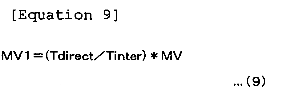
- Further, as shown in FIG. 7, consider a case where the block data covered by the processing in the frame data B uses the frame data F1 as the reference image data in the Direct16x16 mode and uses frame data F3 as the reference image data in the inter 16x16 mode.
In this case, a motion vector MV2 (inter 16x16) obtained by correcting the motion vector MV (inter 16x16) based on the following Equation (10) is used for the judgment of FIG. 5.
In the following Equation (10), "Tdirect" indicates the interval of the display timing between the reference image data F1 and the frame data B, and "Tinter" indicates the interval of the display timing between the frame data B and the reference image data F3. -

- The present embodiment is an embodiment corresponding to the fourth to sixth invention.
First, an explanation will be given of the relationships between the components of the present embodiment and the components of the present invention.
The generating means of the fourth invention is realized by aprocessing circuit 63 of anintra-prediction circuit 41a shown in FIG. 9 calculating indicator data SATDa based on Equation (12) explained later at step ST22 shown in FIG. 10.
The selecting means of the fourth invention is realized by calculating indicator data COSTai based on Equation (11) explained later at step ST22 shown in FIG. 10 and executing step ST24 by theprocessing circuit 63.
As will be explained later, the processing of calculating the indicator data SATD (first indicator data) by theintra-prediction circuit 41a corresponds to the first routine of the fifth invention or the first process of the sixth invention.
The processing of specifying Max4x4 by theintra-prediction circuit 41a corresponds to the second routine of the fifth invention or the second process of the sixth invention. The processing of calculating the indicator data SATDa (second indicator data) based on Equation (12) explained later by theintra-prediction circuit 41a corresponds to the third routine of the fifth invention or the third process of the sixth invention.
The processing of calculating the indicator data COSTai (third indicator data) based on Equation (11) explained later and performing step ST24 shown in FIG. 10 by theintra-prediction circuit 41a corresponds to the fourth routine of the fifth invention or the fourth process of the sixth invention.
The block data of the present embodiment corresponds to the block data of the present invention. - In the same way, the generating means of the fourth invention is realized by a
processing circuit 83 of a motion prediction andcompensation circuit 43a shown in FIG. 13 calculating the indicator data SATDa based on Equation (15) explained later at step ST42 shown in FIG. 14.
The selecting means of the fourth invention is realized by calculating the indicator data COSTam based on Equation (14) explained later at step ST22 shown in FIG. 14 and executing step ST44 by theprocessing circuit 83.
As will be explained later, the processing of calculating the indicator data SATD (first indicator data) by the motion prediction andcompensation circuit 43a corresponds to the first routine of the fifth invention or the first process of the sixth invention.
The processing of specifying Max4x4 by the motion prediction andcompensation circuit 43a corresponds to the second routine of the fifth invention or the second process of the sixth invention.
The processing of calculating the indicator data SATDa (second indicator data) based on Equation (15) explained later by the motion prediction and compensation circuit43a corresponds to the third routine of the fifth invention or the third process of the sixth invention.
The processing of calculating the indicator data COSTam (third indicator data) based on Equation (14) explained later and performing step ST44 shown in FIG. 14 by the motion prediction andcompensation circuit 43a corresponds to the fourth routine of the fifth invention or the fourth process of the sixth invention. - Each of the programs PRG2 and PRG3 of the present embodiment corresponds to the program of the fifth invention.
- Below, a detailed explanation will be given of the coding device according to the present embodiment.
FIG. 8 is an overall view of the configuration of a coding device 2a according to the embodiment of the present invention.
As shown in FIG. 8, the coding device 2a has for example an A/D conversion circuit 22,frame rearrangement circuit 23,computation circuit 24,orthogonal transform circuit 25,quantization circuit 26,reversible coding circuit 27,buffer 28,inverse quantization circuit 29, inverseorthogonal transform circuit 30,frame memory 31,rate control circuit 32,adder circuit 33,deblock filter 34,intra-prediction circuit 41a, motion prediction andcompensation circuit 43a, andselection circuit 44.
In FIG. 7, components given the same notations as those of FIG. 2 are the same as those explained in the first embodiment.
The coding device 2a of the present embodiment is characterized in theintra-prediction circuit 41a and the motion prediction andcompensation circuit 43a. - The
intra-prediction circuit 41a generates the prediction image data PIi of the macro block MB covered by the processing for each of a plurality of prediction modes, for example intra 4x4 mode and intra 16x16 mode, and generates the indicator data COSTai serving as the indicator of the code amount of the encoded data based on this and the macro block MB covered by the processing in the original image data S23.
Then, theintra-prediction circuit 41a selects the intra-prediction mode giving the smallest indicator data COSTai.
Theintra-prediction circuit 41a outputs the prediction image data PIi generated corresponding to the finally selected intra-prediction mode and the indicator data COSTai to theselection circuit 44.
When receiving as input the selection signal S44 indicating that the intra-prediction mode was selected, theintra-prediction circuit 41a outputs the prediction mode IMP indicating the finally selected intra-prediction mode to thereversible coding circuit 27.
Note sometimes the intra-prediction coding by theintra-prediction circuit 41a is carried out even for the macro block MB belonging to the P slice or the B slice. - The
intra-prediction circuit 41a generates for example the indicator data COSTai based on the following Equation (11). -

- In the above Equation (11), "i" is for example an identification number added to each of the block data of sizes corresponding to the intra-prediction modes forming the macro block MB covered by the processing.
Namely, theintra-prediction circuit 41a calculates "SATDa+header_cost (mode))" for all block data forming the macro block MB covered by the processing and adds them to calculates the indicator data COSTai.
The "header_cost (mode)" is indicator data serving as an indicator of the code amount of the header data including the selected intra-prediction mode, the quantization parameter (quantization scale), etc. and indicates a different value according to the intra-prediction mode.
Further, SATDa is indicator data serving as an indicator of the code amount of the difference image data between the block data in the macro block MB covered by the processing and previously determined block data (prediction block data) around the block data.
In the present embodiment, the prediction image data PIi is defined by one or more prediction block data. - The present embodiment is characterized in the method of calculation of SATDa.
- The
intra-prediction circuit 41a calculates the indicator data SATDa for the intra 16x16 mode and the intra 4x4 mode as shown in FIG. 12(A) and the following Equation (12).
- "SATD" in the above Equation (12) is the same as in Equation (5) explained in the first embodiment.
Note that in the present embodiment, theintra-prediction circuit 41a performs the computation of the above Equation (5) in units of 4x4 pixel data for block data comprised of 16x16 pixel data and adds the results to calculate SATD.
Namely, SATD is for example the data after applying a Hadamard transform to the sum of the absolute differences between the pixel data of the block data Org covered by the processing and the prediction image data (reference block data) Pre.
Here, theintra-prediction circuit 41a specifies the maximum value among the-computation results of Equation (5) performed for each 4x4 pixel data in the block data and defines that as Max4x4.
Then, theintra-prediction circuit 41a adds "Max4x4*16" to SATD and divides the result by 2 to calculate the indicator data SATDa.
By using the above Equation (12), theintra-prediction circuit 41a is able to calculate the indicator data SATDa in which the influence of Max4x4 (maximum value of the difference) is reflected more strongly in comparison with the case where only SATD is used. - Note that in place of SATD, the SAD shown in Equation (3) of the first embodiment may be used as well.
Further, in place of SATD, another indicator representing distortion or residue such as SSD defined in MPEG4 and AVC may be used as well. - FIG. 9 shows an example of the hardware configuration of the
intra-prediction circuit 41a shown in FIG. 8.
As shown in FIG. 9, theintra-prediction circuit 41a has for example aninterface 61, amemory 62, and aprocessing circuit 63 all connected via adata line 60.
Theinterface 61 performs the input/output of data with theframe rearrangement circuit 23, thereversible coding circuit 27, and theframe memory 31.
Thememory 62 stores the program PRG2 and various data used for processing of theprocessing circuit 63.
Theprocessing circuit 63 centrally controls the processing of theintra-prediction circuit 41a according to the program PRG2 read out from thememory 62. - Below, an explanation will be given of an example of the operation of the
intra-prediction circuit 41a.
The operation of theintra-prediction circuit 41a shown below is controlled by theprocessing circuit 63 according to the program PRG2.
FIG. 10 is a flow chart for explaining the example of the operation of theintra-prediction circuit 41a.
Theintra-prediction circuit 41a performs the following processing for the block data covered by the processing in the original image data S23. - The
intra-prediction circuit 41a specifies a not yet processed intra-prediction mode among the plurality of intra-prediction modes including the intra 16x16 mode and intra 4x4 mode. - The
intra-prediction circuit 41a calculates the indicator data COSTai by the means explained by using the above Equation (12) for the intra-prediction mode specified at step ST21. - The
intra-prediction circuit 41a judges whether or not the processing of step ST22 has ended for all intra-prediction modes, proceeds to step ST24 when judging the end, and returns to step ST21 when not judging so. - The
intra-prediction circuit 41a selects the smallest intra-prediction mode among indicator data COSTai calculated at step ST22 for all intra-prediction modes. - The
intra-prediction circuit 41a outputs the prediction image data PIi and the indicator data COSTai generated corresponding to the intra-prediction mode selected at step ST24 to theselection circuit 44. - The
intra-prediction circuit 41a judges whether or not the selection signal S44 indicating that the intra-prediction mode was selected was input from theselection circuit 44 at the predetermined timing, proceeds to step ST27 when judging that the selection signal S44 was input, and ends the processing when not judging so. - The
intra-prediction circuit 41a outputs the intra-prediction mode IPM selected at step S24 to thereversible coding circuit 27. - Note that, it is also possible if the
intra-prediction circuit 41a is provided with for example aSATD calculation circuit 71, a maximumvalue specifying circuit 72, aCOST calculation circuit 73, and amode judgment circuit 74 as shown in FIG. 11 in place of the configuration shown in FIG. 9.
Here, theSATD calculation circuit 71 performs the computation of the above Equation (5) and adds the results to calculate SATD.
Further, the maximumvalue specifying circuit 72 specifies the maximum value among the computation results of Equation (5) performed for each 4x4 pixel data in the block data and defines that as Max4x4.
TheCOST calculation circuit 73 adds "Max4x4*16" to SATD and divides the result by 2 to calculate the indicator data SATDa.
Further, themode judgment circuit 74 performs the processing of step ST24 shown in FIG. 10. - The motion prediction and
compensation circuit 43a generates the motion vectors MV of the block data covered by the processing and the prediction image data in units of the block data defined by the motion prediction and compensation mode based on the reference image data encoded in the past and stored in theframe memory 31 for each of a plurality of motion prediction and compensation modes in the case where the macro block MB covered by the processing of the original image data S23 input from theframe rearrangement circuit 23 is inter-coded.
The size of the block data and the reference image data REF are defined by for example the motion prediction and compensation mode.
Further, the motion prediction andcompensation circuit 43a generates the indicator data COSTam serving as the indicator of the code amount of the encoded data based on the macro block MB covered by the processing in the original image data S23 and the prediction block data (prediction image data PIm) thereof for each of the motion prediction and compensation modes.
Then, the motion prediction andcompensation circuit 43a selects the motion prediction and compensation mode giving the smallest indicator data COSTam.
The motion prediction andcompensation circuit 43a outputs the prediction image data PIm generated corresponding to the finally selected motion prediction and compensation mode and the indicator data COSTma to theselection circuit 44.
The motion prediction andcompensation circuit 43a outputs the motion vector generated corresponding to the finally selected motion prediction and compensation mode or the difference motion vector between the motion vector and the prediction motion vector to thereversible coding circuit 27.
The motion prediction andcompensation circuit 43a outputs the finally selected motion prediction and compensation mode MEM to thereversible coding circuit 27.
The motion prediction andcompensation circuit 43a outputs the identification data of the reference image data (reference frame) selected in the motion prediction and compensation processing to thereversible coding circuit 27. - The motion prediction and
compensation circuit 43a generates for example the indicator data COSTam based on the following Equation (13).
- In the above Equation (13), "i" is for example an identification number added to each of the block data of sizes corresponding to the motion prediction and compensation modes forming the macro block MB covered by the processing.
Namely, the motion prediction andcompensation circuit 43a calculates "SATDa+header cost (mode))" for all block data forming the macro block MB covered by the processing and adds them to calculate the indicator data COSTam.
The "header_cost (mode)" is indicator data serving as an indicator of the code amount of the header data including the motion vector or the difference motion vector thereof, the identification data of the reference image data, the selected motion prediction and compensation mode, the quantization parameter (quantization scale), etc. and indicates a different value according to the motion prediction and compensation mode.
Further, SATDa is indicator data serving as an indicator of the code amount of the difference image data between the block data in the macro block MB covered by the processing and previously determined block data (prediction block data) around the block data.
In the present embodiment, the prediction image data PIi is defined by one or more prediction block data. - The present embodiment is characterized by the method of calculation of SATDa.
The motion prediction andcompensation circuit 43a calculates the indicator data SATDa for the inter 16x16 mode, intra 16x16 mode, intra 4x4 mode, Skip mode, and Direct16x16 mode explained in the first embodiment as shown in FIG. 12(A) and the following Equation (14).
- The "SATD" in the above Equation (14) is the same as in Equation (5) explained in the first embodiment.
Note that the motion prediction andcompensation circuit 43a performs the computation of the above Equation (5) in units of 4x4 pixel data for the block data comprised by 16x16 pixel data and adds the results to calculate SATD.
Namely, SATD is for example the data after applying a Hadamard transform to the sum of the absolute differences between the pixel data of the block data Org covered by the processing and the prediction image data (reference block data) Pre.
Here, the motion prediction andcompensation circuit 43a specifies the maximum value among the computation results of Equation (5) performed for each 4x4 pixel data in the block data and defines that as Max4x4.
Then, the motion prediction andcompensation circuit 43a adds "Max4x4*16" to SATD and divides the result by 2 to calculate the indicator data SATDa.
By using the above Equation (14), the motion prediction andcompensation circuit 43a is able to calculate indicator data SATDa in which the influence of Max4x4 (maximum value of the difference) is reflected more strongly in comparison with the case where only SATD is use - Further, the motion prediction and
compensation circuit 43a calculates the indicator data SATDa for the inter 8x16 mode and the inter 16x8 mode as shown in FIG. 12(B) and the following Equation (15).
- "SATD" in the above Equation (15) is the same as in Equation (5) explained in the first embodiment.
Note that the motion prediction andcompensation circuit 43a performs the computation of the above Equation (5) in units of 4x4 pixel data for the block data comprised by 8x16 or 16x8 pixel data and adds the results to calculates SATD.
Namely, SATD is for example the data after applying a Hadamard transform to the sum of the absolute differences between the pixel data of the block data Org covered by the processing and the prediction image data (reference block data) Pre.
Here, the motion prediction andcompensation circuit 43a specifies the maximum value among the computation results of Equation (5) performed for each 4x4 pixel data in the block data, and defines that as Max4x4.
Then, the motion prediction andcompensation circuit 43a adds "Max4x4*8" to SATD and divides the result by 2 to calculate the indicator data SATDa.
By using the above Equation (15), the motion prediction andcompensation circuit 43a is able to calculate indicator data SATDa in which the influence of Max4x4 (maximum value of the difference) is reflected more strongly in comparison with the case where only SATD is used. - Further, the motion prediction and
compensation circuit 43a calculates the indicator data SATDa for the inter 8x8 mode and the Direct8x8 mode explained in the first embodiment as shown in FIG. 12(C) and the following Equation (16).
- "SATD" in the above Equation (16) is the same as in Equation (5) explained in the first embodiment.
Note that the motion prediction andcompensation circuit 43a performs the computation of the above Equation (5) in units of 4x4 pixel data for the block data comprised by 8x8 pixel data and adds the results to calculates SATD.
Namely, SATD is for example the data after applying a Hadamard transform to the sum of the absolute differences between the pixel data of the block data Org covered by the processing and the prediction image data (reference block data) Pre.
Here, the motion prediction andcompensation circuit 43a specifies the maximum value among the computation results of Equation (5) performed for each 4x4 pixel data in the block data and defines that as Max4x4.
Then, the motion prediction andcompensation circuit 43a adds "Max4x4*4" to SATD and divides the result by 2 to calculate the indicator data SATDa.
By using the above Equation (16), the motion prediction andcompensation circuit 43a is able to calculate indicator data SATDa in which the influence of Max4x4 (maximum value of the difference) is reflected more strongly in comparison with the case where only SATD is used. - Further, the motion prediction and
compensation circuit 43a calculates the indicator data SATDa for the inter 4x8 mode and the inter 8x4 mode as shown in FIG. 12(D) and the following
- "SATD" in the above Equation (17) is the same as in Equation (5) explained in the first embodiment.
Note that the motion prediction andcompensation circuit 43a performs the computation of the above Equation (5) in units of 4x4 pixel data for the block data comprised by 8x4 or 4x8 pixel data and adds the results to calculate SATD.
Namely, SATD is for example the data after applying a Hadamard transform to the sum of the absolute differences between the pixel data of the block data Org covered by the processing and the prediction image data (reference block data) Pre.
Here, the motion prediction andcompensation circuit 43a specifies the maximum value among the computation results of Equation (5) performed for each 4x4 pixel data in the block data and defines that as Max4x4.
Then, the motion prediction andcompensation circuit 43a adds "Max4x4*2" to SATD and divides the result by 2 to calculate the indicator data SATDa.
By using the above Equation (17), the motion prediction andcompensation circuit 43a is able to calculate indicator data SATDa in which the influence of Max4x4 (maximum value of the difference) is reflected more strongly in comparison with the case where only SATD is used. - Further, the motion prediction and
compensation circuit 43a calculates the indicator data SATDa for the inter 4x4 mode as shown in FIG. 12(E) and the following Equation (18). -


- "SATD" in the above Equation (18) is the same as in Equation (5) explained in the first embodiment.
Note that the motion prediction andcompensation circuit 43a performs the computation of the above Equation (5) in units of 4x4 pixel data for the block data comprised by 4x4 pixel data and adds the results to calculate SATD.
Namely, SATD is for example the data after applying a Hadamard transform to the sum of the absolute differences between the pixel data of the block data Org covered by the processing and the prediction image data (reference block data) Pre.
Here, the motion prediction andcompensation circuit 43a specifies the maximum value among the computation results of Equation (5) performed for each 4x4 pixel data in the block data and defines that as Max4x4.
Then, the motion prediction andcompensation circuit 43a adds "Max4x4*4" to SATD and divides the result by 2 to calculate the indicator data SATDa.
By using the above Equation (18), the motion prediction andcompensation circuit 43a is able to calculate the indicator data SATDa in which the influence of Max4x4 (maximum value of the difference) is reflected more strongly in comparison with the case where only SATD is used. - Note that, in place of SATD, SAD shown in Equation (3) of the first embodiment may be used as well.
- FIG. 13 is an example of the hardware configuration of the motion prediction and
compensation circuit 43a shown in FIG. 8.
As shown in FIG. 13, the motion prediction andcompensation circuit 43a has for example aninterface 81, amemory 82, and aprocessing circuit 83 all connected via adata line 80.
Theinterface 81 performs the input/output of data with theframe rearrangement circuit 23, thereversible coding circuit 27, and theframe memory 31.
Thememory 82 stores the program PRG3 and various data used for processing of theprocessing circuit 83.
Theprocessing circuit 83 centrally controls the processing of the motion prediction andcompensation circuit 43a according to the program PRG3 read out from thememory 82. - Below, an explanation will be given of an example of the operation of the motion prediction and
compensation circuit 43a.
The operation of the motion prediction andcompensation circuit 43a shown below is controlled by theprocessing circuit 83 according to the program PRG3.
FIG. 14 is a flow chart for explaining the example of the operation of the motion prediction andcompensation circuit 43a.
The motion prediction andcompensation circuit 43a performs the following processing for the block data covered by the processing in the original image data S23. - The motion prediction and
compensation circuit 43a specifies a not yet processed motion prediction and compensation mode among a plurality of motion prediction and compensation modes including the inter 16x16 mode, Skip mode, Direct16x16 mode, inter 8x16 mode, inter 16x8 mode, inter 8x8 mode, Direct8x8 mode, inter 4x8 mode, inter 8x4 mode, and inter 4x4 mode. - The motion prediction and
compensation circuit 43a calculates the indicator data COSTam by the above-explained means for the motion prediction and compensation mode specified at step ST41. - The motion prediction and
compensation circuit 43a judges whether or not the processing of step ST42 was ended for all motion prediction and compensation modes, proceeds to step ST44 when judging the end, and returns to step T41 when not judging so. - The motion prediction and
compensation circuit 43a selects the smallest motion prediction and compensation mode among the indicator data COSTam calculated at step ST42 for all motion prediction and compensation modes. - The motion prediction and
compensation circuit 43a outputs the prediction image data PImi generated corresponding to the motion prediction and compensation mode selected at step ST44 and the indicator data COSTam to theselection circuit 44. - The motion prediction and
compensation circuit 43a judges whether or not the selection signal S44 indicating that the motion prediction and compensation mode was selected was input from theselection circuit 44 at the predetermined timing, proceeds to step ST47 when judging the input, and ends the processing when not judging so. - The motion prediction and
compensation circuit 43a outputs the motion prediction and compensation mode MPM selected at step ST44, the motion vector MV, and the identification data of the reference image data to thereversible coding circuit 27. - Note that it is also possible if the motion prediction and
compensation circuit 43a is provided with for example aSATD calculation circuit 91, a maximumvalue specifying circuit 92, aCOST calculation circuit 93, and amode judgment circuit 94 as shown in FIG. 15 in place of the configuration shown in FIG. 13.
Here, theSATD calculation circuit 91 performs the computation of the above Equation (5) and adds the results to calculates SATD.
Further, the maximumvalue specifying circuit 92 specifies the maximum value among computation results of Equation (5) performed for each 4x4 pixel data in the block data and defines that as Max4x4.
TheCOST calculation circuit 93 calculates the indicator data SATDa by using SATD as explained above.
Further, themode judgment circuit 74 performs the processing of step ST44 shown in FIG. 14. - The example of the overall operation of the coding device 2a is the same as that of the
coding device 2 of the first embodiment except theintra-prediction circuit 41a and the motion prediction andcompensation circuit 43 perform the above-explained operation.
Note that in the present embodiment as well, it is also possible even if all indicator data COSTai and COSTam generated by theintra-prediction circuit 41a and the motion prediction andcompensation circuit 43a are output to theselection circuit 44, and theselection circuit 44 specifies the smallest indicator data. - As explained above, the coding device 2a uses the indicator data STDAa in which the influence of Max4x4 (maximum value of the difference) is reflected strongly more than the case where only the SATD is used in the mode selection of the
intra-prediction circuit 41a and the motion prediction andcompensation circuit 43a.
By this reason, according to the coding device 2a, when the code amount of part of the blocks in the macro block covered by the processing is large and the code amount of most other blocks is small, it is possible to select a suitable mode from the viewpoint of the image quality for the coding of that part of the blocks. - In the second embodiment explained above, the case of calculating the indicator data STDAa based on FIG. 12 and Equation (12) and Equations (14) to (18) was exemplified, but in the present embodiment, the
intra-prediction circuit 41a and the motion prediction andcompensation circuit 43a calculate the indicator data SATDa as shown in FIG. 16 and the following Equations (19) to (23).
In the following Equations (19) to (23), a, b, c, d, e, f, g, h, i, and j are predetermined coefficients.
Here, the coefficients a, c, e, g, and i correspond to the first coefficient of the fourth invention, and the coefficients b, d, f, h, and j correspond to the second coefficient of the fourth invention. - For example, the
intra-prediction circuit 41a calculates the indicator data SATDa based on FIG. 16(A) and the following Equation (19) in the inter 16x16 mode.
- Further, the
intra-prediction circuit 41a and the motion prediction andcompensation circuit 43a calculate the indicator data SATDa based on FIG. 16(B) and the following Equation (20) in the intra 16x16 mode, intra 4x4 mode, Skip mode, and Direct16x16 mode.
- Further, the motion prediction and
compensation circuit 43a calculates the indicator data SATDa based on FIG. 16 (C) and the following Equation (21) in the inter 8x16 mode and the inter 16x8 mode.
- Further, the motion prediction and
compensation circuit 43a calculates the indicator data SATDa based on FIG. 16(D) and the following Equation (22) in the inter 8x8 mode and the Direct8x8 mode.
- Further, the motion prediction and
compensation circuit 43a calculates the indicator data SATDa based on FIG. 16(E) and the following Equation (23) in the inter 4x8 mode and the inter 8x4 mode.
- Further, the motion prediction and
compensation circuit 43a calculates the indicator data SATDa based on FIG. 16(F) and the following Equation (24) in the inter 4x4 mode.
- In the present embodiment, it is made possible to set for example the coefficients a, b, c, d, e, f, g, h, i and j from the outside and possible to freely set the weights of SATD and Max4x4.
For example, in the present embodiment, it is also possible to set a=15, b=1, c=7, d=1, e=1, f=1, g=3, h=1, i=1, and j=1. - The present invention is not limited to the above-explained embodiments.
The present invention may use modes other than the intra-prediction mode and the motion prediction and compensation mode explained above. - The invention can be applied to a system for coding image data.
Claims (15)
- An image processing apparatus used for generating a motion vector of block data of a block covered by processing among a plurality of blocks defined in a two-dimensional image region and encoding the motion vector and a difference between prediction block data generated based on the motion vector and the block data covered by the processing, comprising:a judging means for judging whether or not the difference between motion vectors generated for each of a first mode of predicting the motion vector of the block data covered by the processing from the motion vector of other block data and not encoding the predicted motion vector and a second mode of generating the motion vector of the block data covered by the processing based on the difference between the block data covered by the processing and the block data in a reference image data and encoding the motion vector and difference image data between the block data covered by the processing and the reference block data corresponding to the generated motion vector in the reference image data exceeds a predetermined standard; anda selecting means for selecting the second mode when the judging means judges that the difference exceeds the predetermined standard and selecting a mode between the first mode and the second mode in which the coded data amount by the encoding becomes the minimum when the judging means judges that the difference does not exceed the predetermined standard.
- An image processing apparatus as set forth in claim 1, further comprising a provision means for performing processing for providing identification data of said mode selected by said selecting means and data defined by said selected mode.
- An image processing apparatus as set forth in claim 1, wherein said selecting means uses said first mode further encoding difference image data between said block data covered by the processing and reference block data which said predicted motion vector in reference image data indicates.
- An image processing apparatus as set forth in claim 3, wherein said selecting means uses said first mode performing prediction from a motion vector of said other block data in frame data or field data to which the block data covered by processing belongs.
- An image processing apparatus as set forth in claim 3, wherein said selecting means uses said first mode performing prediction from a motion vector of said other block data in frame data or field data different from the frame data or the field data to which the block data covered by processing belongs.
- An image processing apparatus as set forth in claim 1, wherein said selecting means uses said first mode does not provide to a decoding side the difference image data between said block data covered by processing and reference block data which said predicted motion vector in reference image data indicates.
- An image processing apparatus as set forth in claim 1, wherein when the frame data or the field data used for generating said motion vector differs between said first mode and said second mode, said judging means converts said motion vector generated for one mode so as to correspond to the reference image data used for the other mode and used the converted motion vector to generate said difference.
- A program for making a computer execute processing for generating a motion vector of block data of a block covered by the processing among a plurality of blocks defined in a two-dimensional image region and encoding the motion vector and a difference between prediction block data generated based on the motion vector and the block data covered by the processing, including:a first routine of generating the motion vector for each of a first mode of predicting the motion vector of the block data covered by the processing from the motion vector of the other block data and not encoding the predicted motion vector and a second mode of generating the motion vector of the block data covered by the processing based on the difference between the block data covered by the processing and the block data in a reference image data and encoding the motion vector and a difference image data between the block data covered by the processing and the reference block data corresponding to the generated motion vector in the reference image data;a second routine of judging whether or not the difference between the motion vector of the first mode generated in the first routine and the motion vector of the second mode exceeds a predetermined standard; anda third routine of selecting the second mode when judging that the difference exceeds the predetermined standard in the second routine and selecting the mode between the first mode and the second mode in which the coded data amount by the encoding becomes the minimum when judging that the difference does not exceed the predetermined standard.
- An image processing method including having a computer executes processing for generating a motion vector of block data of a block covered by processing among a plurality of blocks defined in a two-dimensional image region and encoding the motion vector and a difference between prediction block data generated based on the motion vector and the block data covered by the processing, comprising:a first process of generating the motion vector for each of a first mode of predicting the motion vector of the block data covered by the processing from the motion vector of other block data and not encoding the predicted motion vector and a second mode of generating the motion vector of the block data covered by the processing based on the difference between the block data covered by the processing and the block data in a reference image data and encoding the motion vector and difference image data between the block data covered by the processing and the reference block data corresponding to the generated motion vector in the reference image data;a second process of judging whether or not the difference between the motion vector of the first mode generated in the first process and the motion vector of the second mode exceeds a predetermined standard; anda third process of selecting the second mode when judging that the difference exceeds the predetermined standard in the second process and selecting the mode between the first mode and the second mode in which the code amount by the encoding becomes the minimum when judging that the difference does not exceed the predetermined standard.
- An image processing apparatus used for encoding block data of a block covered by processing among one or more blocks forming a macro block defined in a two-dimensional image region based on that block data and prediction block data of the block data, comprising:a generating means for generating first indicator data in accordance with a difference between one or more unit block data forming the block data covered by the processing and unit block data in prediction block data corresponding to this unit block data in units of the unit block data, specifying first indicator data indicating the maximum data among the first indicator data, and generating second indicator data in which the specified first indicator data is strongly reflected as a value in comparison with a sum of the first indicator data generated for the unit block data forming the block data covered by the processing based on the first indicator data; anda selecting means for selecting the mode giving the smallest third indicator data in accordance with the sum of the second indicator data generated by the generating means for the one or more block data forming a macro block covered by the processing among a plurality of modes in which at least one of the size of the block data defined for the macro block covered by the processing, existence of encoding of the motion vector, and existence of encoding of the difference are different from each other.
- An image processing apparatus as set forth in claim 10, wherein said plurality of modes incluedes at least one of an intra-prediction mode and motion prediction and compensation mode.
- An image processing apparatus as set forth in claim 10, wherein said generating means generates said second indicator data corresponding to a value of a sum of said first indicator data generated for said unit block data forming said block data covered by processing plus the number of said unit block data forming said block data covered by processing multiplied with said specified first indicator data.
- An image processing apparatus as set forth in claim 10, wherein said generating means generates said second indicator data corresponding to a value of a sum of said first indicator data generated for said unit block data forming said block data covered by processing multiplied with a first coefficient plus the number of said unit block data forming said block data covered by processing and a second coefficient multiplied with said specified first indicator data.
- A program for making a computer execute processing for encoding block data of a block covered by processing among one or more blocks forming a macro block defined in a two-dimensional image region based on the block data and prediction block data of the block data, having:a first routine of generating first indicator data in accordance with a difference between one or more unit block data forming the block data covered by the processing and unit block data in prediction block data corresponding to this unit block data in units of the unit block data;a second routine of specifying the first indicator data indicating the maximum data among the first indicator data generated in the first routine;a third routine of generating second indicator data in which the first indicator data specified in the second routine is strongly reflected as a value in comparison with the sum of the first indicator data generated for the unit block data forming the block data covered by the processing based on the first indicator data generated in the first routine; anda fourth routine of selecting the mode giving the smallest third indicator data in accordance with the sum of the second indicator data generated in the third routine for the one or more block data forming the macro block covered by the processing among a plurality of modes in which at least one of the size of the block data defined for the macro block covered by the processing, existence of encoding of the motion vector, and existence of encoding of the difference are different from each other.
- An image processing method including having a computer execute processing for encoding block data of a block covered by the processing among one or more blocks forming a macro block defined in the two-dimensional image region based on the block data and the prediction block data of the block data, including:a first process of generating first indicator data in accordance with the difference between one or more unit block data forming the block data covered by the processing and the unit block data in the prediction block data corresponding to this unit block data in units of the unit block data;a second process of specifying the first indicator data indicating the maximum data among the first indicator data generated in the first process;a third process of generating second indicator data in which the first indicator data specified in the second process is strongly reflected as a value in comparison with the sum of the first indicator data generated for the unit block data forming the block data covered by the processing based on the first indicator data generated in the first process; anda fourth process of selecting the mode giving the smallest third indicator data in accordance with the sum of the second indicator data generated in the third process for the one or more block data forming the macro block covered by the processing among a plurality of modes in which at least one of the size of the block data defined for the macro block covered by the processing, existence of encoding of the motion vector, and existence of encoding of the difference are different from each other.
Applications Claiming Priority (2)
| Application Number | Priority Date | Filing Date | Title |
|---|---|---|---|
| JP2004165453A JP2005348093A (en) | 2004-06-03 | 2004-06-03 | Image processing apparatus, program thereof, and method thereof |
| PCT/JP2005/010020 WO2005120077A1 (en) | 2004-06-03 | 2005-06-01 | Image processing device, program thereof, and method thereof |
Publications (1)
| Publication Number | Publication Date |
|---|---|
| EP1753247A1 true EP1753247A1 (en) | 2007-02-14 |
Family
ID=35463208
Family Applications (1)
| Application Number | Title | Priority Date | Filing Date |
|---|---|---|---|
| EP20050745737 Withdrawn EP1753247A1 (en) | 2004-06-03 | 2005-06-01 | Image processing device, program thereof, and method thereof |
Country Status (7)
| Country | Link |
|---|---|
| US (1) | US20080049837A1 (en) |
| EP (1) | EP1753247A1 (en) |
| JP (1) | JP2005348093A (en) |
| KR (1) | KR20070033346A (en) |
| CN (1) | CN1993993A (en) |
| TW (1) | TWI262726B (en) |
| WO (1) | WO2005120077A1 (en) |
Cited By (4)
| Publication number | Priority date | Publication date | Assignee | Title |
|---|---|---|---|---|
| WO2007125458A3 (en) * | 2006-04-27 | 2008-01-10 | Koninkl Philips Electronics Nv | Method and apparatus for encoding/transcoding and decoding |
| US20090310682A1 (en) * | 2006-03-09 | 2009-12-17 | Nec Corporation | Dynamic image encoding method and device and program using the same |
| ITTO20090356A1 (en) * | 2009-05-04 | 2010-11-05 | St Microelectronics Srl | "PROCEDURE AND DEVICE FOR DIGITAL VIDEO CODING, RELATIVE SIGNAL AND IT PRODUCT" |
| TWI400957B (en) * | 2007-10-05 | 2013-07-01 | Thomson Licensing | Methods for incorporating video usability information (vui) within a multi-view video (mvc) coding system |
Families Citing this family (17)
| Publication number | Priority date | Publication date | Assignee | Title |
|---|---|---|---|---|
| KR101270167B1 (en) | 2006-08-17 | 2013-05-31 | 삼성전자주식회사 | Method and apparatus of low complexity for compressing image, method and apparatus of low complexity for reconstructing image |
| US8311120B2 (en) | 2006-12-22 | 2012-11-13 | Qualcomm Incorporated | Coding mode selection using information of other coding modes |
| WO2008084817A1 (en) * | 2007-01-09 | 2008-07-17 | Kabushiki Kaisha Toshiba | Image encoding and decoding method and device |
| US8233537B2 (en) * | 2007-03-19 | 2012-07-31 | Texas Instruments Incorporated | Efficient implementation of H.264 4 by 4 intra prediction on a VLIW processor |
| JP4709187B2 (en) * | 2007-07-10 | 2011-06-22 | 日本電信電話株式会社 | ENCODING PARAMETER DETERMINING METHOD, ENCODING PARAMETER DETERMINING DEVICE, ENCODING PARAMETER DETERMINING PROGRAM, AND COMPUTER-READABLE RECORDING MEDIUM CONTAINING THE PROGRAM |
| KR101505195B1 (en) * | 2008-02-20 | 2015-03-24 | 삼성전자주식회사 | Direct mode encoding and decoding method |
| KR100939917B1 (en) | 2008-03-07 | 2010-02-03 | 에스케이 텔레콤주식회사 | Coding system through motion prediction and encoding method through motion prediction |
| JP4990927B2 (en) * | 2008-03-28 | 2012-08-01 | 三星電子株式会社 | Method and apparatus for encoding / decoding motion vector information |
| JP5339855B2 (en) * | 2008-10-31 | 2013-11-13 | キヤノン株式会社 | Motion vector search device, motion vector search method, image processing device, image processing method, program, and storage medium |
| SG10201402451XA (en) * | 2009-05-29 | 2014-07-30 | Mitsubishi Electric Corp | Image encoding device, image decoding device, image encoding method, and image decoding method |
| US8594200B2 (en) * | 2009-11-11 | 2013-11-26 | Mediatek Inc. | Method of storing motion vector information and video decoding apparatus |
| JP5341786B2 (en) * | 2010-01-20 | 2013-11-13 | 株式会社メガチップス | Image coding apparatus and image conversion apparatus |
| JP2013034162A (en) * | 2011-06-03 | 2013-02-14 | Sony Corp | Image processing device and image processing method |
| US9161046B2 (en) | 2011-10-25 | 2015-10-13 | Qualcomm Incorporated | Determining quantization parameters for deblocking filtering for video coding |
| JP5798467B2 (en) * | 2011-12-07 | 2015-10-21 | ルネサスエレクトロニクス株式会社 | Coding type determination device, moving image coding device, coding type determination method, moving image coding method, and program |
| KR20240095362A (en) * | 2017-06-26 | 2024-06-25 | 파나소닉 인텔렉츄얼 프로퍼티 코포레이션 오브 아메리카 | Encoding device, decoding device, encoding method and decoding method |
| US12568184B2 (en) * | 2020-07-30 | 2026-03-03 | Nvidia Corporation | Techniques to generate interpolated video frames |
Family Cites Families (11)
| Publication number | Priority date | Publication date | Assignee | Title |
|---|---|---|---|---|
| US5508744A (en) * | 1993-03-12 | 1996-04-16 | Thomson Consumer Electronics, Inc. | Video signal compression with removal of non-correlated motion vectors |
| JP3351705B2 (en) * | 1997-04-25 | 2002-12-03 | 日本ビクター株式会社 | Motion compensation coding apparatus, motion compensation coding method, and recording method on recording medium |
| JP2003513565A (en) * | 1999-10-29 | 2003-04-08 | コーニンクレッカ フィリップス エレクトロニクス エヌ ヴィ | Video coding method |
| JP3720723B2 (en) * | 2001-03-26 | 2005-11-30 | 三菱電機株式会社 | Motion vector detection device |
| EP1347649A1 (en) * | 2002-03-18 | 2003-09-24 | Lg Electronics Inc. | B picture mode determining method and apparatus in video coding system |
| JP3866624B2 (en) * | 2002-06-26 | 2007-01-10 | 日本電信電話株式会社 | Moving picture encoding method, moving picture decoding method, moving picture encoding apparatus, and moving picture decoding apparatus |
| US7154952B2 (en) * | 2002-07-19 | 2006-12-26 | Microsoft Corporation | Timestamp-independent motion vector prediction for predictive (P) and bidirectionally predictive (B) pictures |
| BRPI0411765A (en) * | 2003-06-25 | 2006-08-08 | Thomson Licensing | fast modal interframe decision coding |
| US7609763B2 (en) * | 2003-07-18 | 2009-10-27 | Microsoft Corporation | Advanced bi-directional predictive coding of video frames |
| WO2006096612A2 (en) * | 2005-03-04 | 2006-09-14 | The Trustees Of Columbia University In The City Of New York | System and method for motion estimation and mode decision for low-complexity h.264 decoder |
| US7667371B2 (en) * | 2007-09-17 | 2010-02-23 | Motorola, Inc. | Electronic device and circuit for providing tactile feedback |
-
2004
- 2004-06-03 JP JP2004165453A patent/JP2005348093A/en active Pending
-
2005
- 2005-06-01 WO PCT/JP2005/010020 patent/WO2005120077A1/en not_active Ceased
- 2005-06-01 KR KR20067025489A patent/KR20070033346A/en not_active Withdrawn
- 2005-06-01 EP EP20050745737 patent/EP1753247A1/en not_active Withdrawn
- 2005-06-01 CN CNA200580026529XA patent/CN1993993A/en active Pending
- 2005-06-01 US US11/628,301 patent/US20080049837A1/en not_active Abandoned
- 2005-06-02 TW TW94118218A patent/TWI262726B/en active
Non-Patent Citations (1)
| Title |
|---|
| See references of WO2005120077A1 * |
Cited By (9)
| Publication number | Priority date | Publication date | Assignee | Title |
|---|---|---|---|---|
| US20090310682A1 (en) * | 2006-03-09 | 2009-12-17 | Nec Corporation | Dynamic image encoding method and device and program using the same |
| EP1993292A4 (en) * | 2006-03-09 | 2010-09-01 | Nec Corp | Dynamic image encoding method and device and program using the same |
| US8428136B2 (en) * | 2006-03-09 | 2013-04-23 | Nec Corporation | Dynamic image encoding method and device and program using the same |
| WO2007125458A3 (en) * | 2006-04-27 | 2008-01-10 | Koninkl Philips Electronics Nv | Method and apparatus for encoding/transcoding and decoding |
| TWI400957B (en) * | 2007-10-05 | 2013-07-01 | Thomson Licensing | Methods for incorporating video usability information (vui) within a multi-view video (mvc) coding system |
| TWI400958B (en) * | 2007-10-05 | 2013-07-01 | Thomson Licensing | Computer-programmable storage medium for incorporating video usability information (vui) within a multi-view video (mvc) coding system |
| TWI401966B (en) * | 2007-10-05 | 2013-07-11 | Thomson Licensing | Methods and apparatus for incorporating video usability information (vui) within a multi-view video (mvc) coding system |
| ITTO20090356A1 (en) * | 2009-05-04 | 2010-11-05 | St Microelectronics Srl | "PROCEDURE AND DEVICE FOR DIGITAL VIDEO CODING, RELATIVE SIGNAL AND IT PRODUCT" |
| US8699573B2 (en) | 2009-05-04 | 2014-04-15 | Stmicroelectronics S.R.L. | Method and device for digital video encoding, corresponding signal and computer-program product |
Also Published As
| Publication number | Publication date |
|---|---|
| WO2005120077A1 (en) | 2005-12-15 |
| TW200614821A (en) | 2006-05-01 |
| TWI262726B (en) | 2006-09-21 |
| US20080049837A1 (en) | 2008-02-28 |
| KR20070033346A (en) | 2007-03-26 |
| CN1993993A (en) | 2007-07-04 |
| JP2005348093A (en) | 2005-12-15 |
Similar Documents
| Publication | Publication Date | Title |
|---|---|---|
| EP1753247A1 (en) | Image processing device, program thereof, and method thereof | |
| KR101177031B1 (en) | Method and apparatus for minimizing number of reference pictures used for inter-coding | |
| AU2006320064B2 (en) | Image encoding/image decoding method and image encoding/image decoding apparatus | |
| US7058127B2 (en) | Method and system for video transcoding | |
| KR101196429B1 (en) | Video transcoding method and apparatus, and motion vector interpolation method | |
| US7792193B2 (en) | Image encoding/decoding method and apparatus therefor | |
| AU2006338425B2 (en) | Moving image encoding/decoding method and device and program | |
| JP5400876B2 (en) | Rate control model adaptation based on slice dependency for video coding | |
| KR101420957B1 (en) | Image encoding device, image decoding device, image encoding method, and image decoding method | |
| EP2437499A1 (en) | Video encoder, video decoder, video encoding method, and video decoding method | |
| EP2675164A1 (en) | Image processing system, image processing method and program | |
| EP2036358A1 (en) | Image encoding/decoding method and apparatus | |
| JP2007089035A (en) | Moving image encoding method, apparatus, and program | |
| CA2218866A1 (en) | Mpeg encoder that concurrently determines video data encoding format and rate control | |
| JP2011229145A (en) | Method of performing hybrid multi-hypothesis prediction in moving picture encoding by encoding unit, and related device | |
| JP2001145113A (en) | Image information conversion apparatus and method | |
| JP4360093B2 (en) | Image processing apparatus and encoding apparatus and methods thereof | |
| US7764740B2 (en) | Fast block mode determining method for motion estimation, and apparatus thereof | |
| WO2010137322A1 (en) | Image encoder, image decoder, image encoding method and image decoding method | |
| US20060193526A1 (en) | Video encoder with low complexity noise reduction | |
| KR20050068687A (en) | Video encoding method for providing motion compensation method based on mesh structure using motion model and video encoding apparatus therefor | |
| JP4747494B2 (en) | Data processing apparatus and method and encoding apparatus | |
| JP4561508B2 (en) | Image processing apparatus, image processing method and program thereof | |
| JP2005244666A (en) | Data processing apparatus, encoding apparatus, and data processing method | |
| JP2004320437A (en) | Data processing device, encoding device and their methods |
Legal Events
| Date | Code | Title | Description |
|---|---|---|---|
| PUAI | Public reference made under article 153(3) epc to a published international application that has entered the european phase |
Free format text: ORIGINAL CODE: 0009012 |
|
| 17P | Request for examination filed |
Effective date: 20061113 |
|
| AK | Designated contracting states |
Kind code of ref document: A1 Designated state(s): DE FR GB |
|
| DAX | Request for extension of the european patent (deleted) | ||
| RBV | Designated contracting states (corrected) |
Designated state(s): DE FR GB |
|
| STAA | Information on the status of an ep patent application or granted ep patent |
Free format text: STATUS: THE APPLICATION HAS BEEN WITHDRAWN |
|
| 18W | Application withdrawn |
Effective date: 20090831 |