EP1753208A1 - Cellular phone - Google Patents
Cellular phone Download PDFInfo
- Publication number
- EP1753208A1 EP1753208A1 EP04735509A EP04735509A EP1753208A1 EP 1753208 A1 EP1753208 A1 EP 1753208A1 EP 04735509 A EP04735509 A EP 04735509A EP 04735509 A EP04735509 A EP 04735509A EP 1753208 A1 EP1753208 A1 EP 1753208A1
- Authority
- EP
- European Patent Office
- Prior art keywords
- superposed
- bodies
- axis
- portable telephone
- extended state
- Prior art date
- Legal status (The legal status is an assumption and is not a legal conclusion. Google has not performed a legal analysis and makes no representation as to the accuracy of the status listed.)
- Granted
Links
Images




Classifications
-
- H—ELECTRICITY
- H04—ELECTRIC COMMUNICATION TECHNIQUE
- H04M—TELEPHONIC COMMUNICATION
- H04M1/00—Substation equipment, e.g. for use by subscribers
- H04M1/02—Constructional features of telephone sets
- H04M1/0202—Portable telephone sets, e.g. cordless phones, mobile phones or bar type handsets
- H04M1/0206—Portable telephones comprising a plurality of mechanically joined movable body parts, e.g. hinged housings
- H04M1/0208—Portable telephones comprising a plurality of mechanically joined movable body parts, e.g. hinged housings characterized by the relative motions of the body parts
- H04M1/0235—Slidable or telescopic telephones, i.e. with a relative translation movement of the body parts; Telephones using a combination of translation and other relative motions of the body parts
- H04M1/0237—Sliding mechanism with one degree of freedom
Definitions
- the present invention relates to a portable telephone in which two bodies thereof are placed in superposed relation, and a part of one body slides relative to the other body to open and close the telephone by expanding and contracting the full length of the telephone in the sliding direction.
- Known conventional portable telephones in which two bodies thereof are placed in superposed relation, and one body slides relative to the other body to open and close the telephone by expanding and contracting the full length of the telephone in the sliding direction, include, as shown in JP-A-2003-110 675 , for example, a portable telephone, in which a guide slot providing a rotation-preventing ability is formed mostly along the full length of each side of one body, and a slide piece provided on the other body is engaged in the guide slot and slides along it for opening and closing the telephone.
- the conventional portable telephone is thus arranged as mentioned above.
- This arrangement Through this arrangement, relative sliding of the two bodies for putting the telephone in the opened state from the state where the two bodies are superposed completely results in exposure of the guide slot to outside, thus imposing restrictions in deliberately designing a decoration for the telephone.
- the exposure of the guide slot provided as a sliding portion causes dirt adhesion to that portion, which may impair smooth sliding. Furthermore, the guide slot provided mostly along the full length of the both edges of the body narrows an available component-mounting space thereof.
- An object of the present invention is to provide a portable telephone in which one body can pull out relative to the other body with an area left where a part of one body is superposed on the other body in the extended state, and a rotation preventing mechanism for preventing the two bodies from relatively rotating is intensively provided within the superposed area in the extended state, which prohibits the rotation preventing mechanism from being exposed to outside during sliding and narrows less available component-mounting space.
- a portable telephone according to the present invention is a portable one in which two bodies thereof are placed in superposed relation, and one body slides relative to the other body to change how far they superpose, thus expanding and contracting the full length of the telephone in the sliding direction, wherein one body can pull out relative to the other body with an area left where a part of one body is superposed on the other body in the extended state, and a rotation preventing mechanism for preventing the two bodies from relatively rotating is intensively provided within the superposed area in the extended state.
- the invention exerts an effect that the rotation preventing mechanism is prohibited from being outwardly exposed during sliding and down-sized mechanism narrows less available component-mounting space.
- FIG. 1 and FIG. 2 show external appearance of the portable telephone according to the first embodiment of the present invention, wherein FIG. 1 shows the closed state thereof, while FIG. 2 does the opened state thereof, respectively.
- the portable telephone 1 roughly composes of two bodies, i.e. one body 2 and the other body 3 superposed thereon. Additionally, as a member concealed from outside and cannot tell whether they belong to the body 2 or to the body 3, the telephone includes a wiring member (a flexible substrate 6, see FIG. 2 and 11 to 13) for connecting these bodies 2 and 3. The wiring member will be touched upon later.
- the body 2 positioned thereunder is referred to as the first body 2, and the body positioned thereon is done as the second body 3.
- the first body 2 is an assembly composed of a lot of combined members, and includes, as the main members viewed from outside, a flat- and rectangular-shaped first base body 20, and a first plate 21 superposed on and secured to the first base body 20. They present external appearance of a flat and rectangular shape as a whole.
- the body 3 is also an assembly composed of many combined members; however, among which only a second base body 30 can be viewed from outside.
- the second base body 30 is of a flat and rectangular shape enough to be substantially superposed on the first body 2, of which portion positioned on its one-end in the longitudinal direction forms a sloping face 30a.
- the second base body 30 is provided with a second plate 31 secured to its interior thereof 30 by means of screws 84 serving as a fastening means to be mentioned later through screw holes 30c formed on the sloping face 30a (see FIG. 2, FIG. 3, and FIG. 4).
- the first body 2 and the second body 3 are arranged to be able to relatively slide in the longitudinal direction to displace from each other. Therefore, one has difficulty in distinguishing which is the fixed side or the moving side.
- an explanation is made for convenience' sake by assuming that the second body 3 moves with respect to the first body 2.
- the portable telephone 1 can take, as shown in FIG. 1, the closed position in which the second body 3 is superposed on the first body 2 with truing up their edges.
- the portable telephone can be displaced to the opened position in which the second body 3 slid in the longitudinal direction and is pulled out relative to the first body 2 from the closed position, as shown in FIG. 2.
- the portable telephone is such a type in which two bodies thereof are placed in superposed relation, one body slides relative to the other body to change how far they superpose, thus expanding and contracting the overall length of the telephone in the sliding direction.
- pulling-out is not permitted without limitation. It is arranged such that a stopper means enables one body (the first body 2) to pull out relative to the other body (the second body 3) with an area left where a part of one body is superposed on the other body within the range of a section L shown in FIG. 2.
- the superposed area is an area where a part of the first body 2 is superposed on the second body 3 within the section L in the Y-axial direction.
- a feature of the portable telephone according to the present invention consists in that a rotation preventing mechanism for preventing the two bodies from relatively rotating is intensively provided within the superposed area in the extended state.
- the section L which is the distance of the superposed area in the Y-axial direction, is set to be approximately half the overall length of each body in the Y-axial direction.
- the section L is the section occupied leftward from the right end in the Y-axial direction, in terms of the first body 2 and is also the section occupied rightward from the left end in the Y-axial direction in terms of the second body 3.
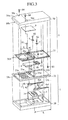
- FIG. 3 shows the disassembled portable telephone 1 in the closed state in FIG. 1.
- FIG. 4 is a plan view showing the portable telephone 1 in the opened state in FIG. 2;
- FIG. 5 is a front view showing the portable telephone 1 shown in FIG. 4, viewed from the X-axial direction;
- FIG. 6 is a sectional view showing the portable telephone 1 taken along the line H-H in FIG. 4;
- FIG. 7 is a partially enlarged sectional view showing a portion of FIG. 6 on an enlarged scale;
- FIG. 8 and FIG. 9 are oblique views showing respective members;
- FIG. 10 is a sectional view showing the portable telephone 1 taken along the line S-S in FIG. 4;
- FIG. 11 is a sectional view showing the portable telephone 1 taken along the line C-C in FIG. 4.
- first body 2 will be described about the first base body 20 and first plate 21, which are the primary structural members thereof, and members placed therebetween.
- the right end of the first base body 20 and that of the first plate 21 in the Y-axial direction are conformed to each other, and the right end of the first base body 30 forms the right end of the first body 2.
- a substrate 5 is secured to a concavity formed in a rightwardly portion on the top of the first base body 20 in the Y-axial direction.
- a connector 5a is provided on the top of the substrate 5.
- two slide rails 4a are secured to the both sides of the substrate 5 mounted on the top of the first base body 20 in the X axial direction, parallel to the base body in the Y-axial direction.
- the slide rail 4a as shown in FIG. 6 and FIG. 7 and in FIG. 8 its cross-sectional shape, is a long member having a groove 4a1 of which upper part opened and is long in the Y-axial direction.
- a slider 4b made of a rectangular block and serving as a sliding piece is slidably fitted in the groove 4a1.
- the slider 4b is slidable along the interior of the groove 4a1 therein, the slider is arranged to stop sliding by the ends of the slit 21b provided in the first plate 21 to be described later.
- the position where the slide rail 4a is disposed is on the top of the first base body 20 and placed within the range of the section L. As discussed hereinabove, while the slider 4b is slidable along the interior of the groove 4a1 formed in the slide rail 4a, the slider is located at the left end of the groove 4a1 in the Y-axial direction in FIG. 3.
- the first plate 21 On the top of the first base body 20 the first plate 21 is secured, the first plate having the thickness thinner than that of the first base body 20 in the Z-axial direction, and being of a size enough to be completely superposed on the first base body 20. Further, a clearance is formed in the central portion in the X-axial direction between the back of the first plate 21 and the top of the first base body 20, as shown in FIG.6 and FIG.7. In FIG. 6 and FIG. 7, connectors 5a positioned in the clearance and members accompanied with them are not shown for simplification.
- first plate 21 On the underside of the first plate 21 grooves are respectively formed for receiving therein the two slide rails 4a, and further, the portion of each of these grooves, corresponding to the just above position of the groove 4a1 of the slide rail 4a is communicated to the upper side by a slit 21 b having the substantially same groove width as that of the groove 4a1.
- the slider 4b slidably fits in, passes through each of these slits 21b, and projects upwardly from the top of the first plate 21. Accordingly, both ends of the slit 21 b in the Y-axial direction, each serving as a stopper of the slider 4b.
- two bosses 21d are provided on the top of the first plate 21.
- Each of these bosses 21 d is provided at the position corresponding to the left end of each slit 21b and adjacent to the slit 21b in the area within the section L, and is formed so as to be projecting upwardly in the Z-axial direction.
- a rectangular opening 21e long in the X-axial direction is formed at the place between these two bosses 21d on the first plate 21 .
- One of the ends of the band-shaped flexible substrate 6 extends through the opening 21e, and a connector 6a provided on one end of the flexible substrate 6 is connected to the connector 5a of the substrate 5.
- the second body 3 will be described about the second base body 30 and second plate 31, which constitutes the primary structural members of the second body, and members placed therebetween.
- the central portion of the concavity forms a rectangular-plate shaped shallow concavity, and the substrate 9 is attached and secured to the shallow concavity (see FIG. 4 and FIG. 11).
- a connector 9a (Not shown in FIG. 3; see FIG. 11) is equipped, and the connector 9a is connected with a connector 6b provided on one end of the flexible substrate 6, the other end of which is connected with the connector 5a as described hereinabove. At that time, the one-end of the flexible substrate 6 is turned around the left end of the second plate 31 and reaches the connector 9a.
- the second plate 31 which is a size smaller than that of the second base body 30 and which is attached and secured to the cavity, is provided with the substrate 9 put therebetween.
- the fastening means is removably fastened to the second plate 31 by unscrewing a screw 83 from below of the right end of the second plate 31, and by unscrewing screws 84 from the upper side of the second base body 30 of the left end thereof.
- mounting eyes 31 a are provided in the area within the section L on the second plate 31, which extends rightwardly from the left end of the second base body 30 in the Y-axial direction corresponding to the longitudinal direction. These mounting eyes 31 a are located, as shown in FIG. 6 and FIG. 7, right above the slider 4b passing through the slit 21b of the first plate 21.
- a screw 81 is screwed into the slider 4b through a screw hole formed on the mounting eye 31a, thus integrally fixing the slider 4b to the mounting 31a.
- the sliders 4b are integrated with the second body 3 (see FIG. 10).
- the second plate 31 has two slits 31b formed in parallel spaced apart from each other in the X-axial direction.
- the boss 21d provided on the first plate 21 is slidably passing through each of these slits 31 b.
- These slits 31 b each extending in the Y-axial direction, and is within the range of the section L.
- an engaging pawl 7 is fixed from above with a screw 82.
- the engaging pawl 7 is of a rectangular-flat-plate form, as shown in FIG. 9, at the center of which a hole 7a is formed for screw, and a notch 7b is formed for engaging with the boss 21d formed on each end thereof in the Y-axial direction. As shown in FIG. 6 and FIG. 7, the engaging pawl 7 is engaged overhanging the step portion provided at the edge of the slit 31b.
- FIG. 12 and FIG. 13 are oblique views each showing perspectively the portable telephone 1;
- FIG. 12 shows the portable telephone 1 in the closed state and corresponds to FIG. 1 and FIG. 3; and
- FIG. 13 shows the portable telephone 1 in the opened state and corresponds to FIG. 2, FIG. 4 to 7, FIG. 10, and FIG. 11.
- the second body 3 is pulled out to the utmost relative to the first body 2, that is, the first body 2 and the second body 3 are superposed within the section L in the state where the slider 4b abuts the end of the slit 21 b in the Y-axial direction.
- the two engaging pawls 7 provided spaced apart from each other in the X-axial direction are engaged, as shown in FIG. 3, FIG. 6, and FIG. 7, such that a face of each of the engaging pawls is opposed to that of the step portion formed at the edge of the slit 31b within the section L, and further, the engaging pawl 7 and the edge of the slit 21b formed in the first plate 21 and the engaging pawl 7 pinch the slit 31b.
- the engaging pawl 7, the boss 21d and the slit 31 b constitute an X-axis-rotation preventing means, which prevents one body from rotating on any one of axes parallel to the X axis relative to either of the fixed first body 2 or the fixed second body 3.
- changes of the shape of the slider 4b into a shape by virtue of which the slider is slidable along the slider rail 4b without getting out of the slide rail 4a for example, to an inverted-T shape in FIG. 6 and FIG. 7, which conducts to reduce a load imposed on the engaging pawl 7 at the time of acting of the moment in the direction opposite to the moment M.
- the engaging pawl 7 is provided separately from the first body 2, and arranged to be detachable therefrom by means of the screw 82. Thereby, it becomes possible to transform the material into one having higher slidability or higher strength.
- the slider 4b integrally provided to the second body 3 fits in the slit 21 b formed in the first plate 21 integrally provided to the first body 2.
- the slider 4b is made of a rectangular block, and the slit 21b has thickness in the Z-axial direction, which brings them into slidably face-to-facedly contact with each other. This securely prevents the second body 3 from rotating on the Z axis relative to the first body 2.
- the slider 4b and the slit 21 b constitute a Z-axis-rotation preventing means for preventing one body from rotating relative to either of the fixed first body 2 and the fixed second body 3 on any one of axes parallel to the Z axis.
- a single slider 4b and its attachment accompanying therewith may be one.
- the two sliders 4b which are provided oppositely in the X-axial direction, are efficiently serviceable as the Z-axis-rotation preventing means.
- the bosses 21d spaced apart from each other in the X-axial direction are arranged to engage in the slits 31 b as shown in FIG. 6 and FIG. 7. Accordingly, it can be said that these members may also constitute the Z-axis-rotation preventing means.
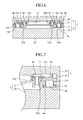
- FIG. 7 and FIG. 14 which are sectional views each showing the portable telephone viewed from the Y-axial direction, the slit 31 b in which the boss 21d fitted and the slit 21 b along which the slider 4b fitted each having thickness in the Z-axial direction (in the vertical direction), and these thicknesses slidably contact with the boss 21d and the slider 4b, respectively.
- the rotation preventing mechanism is provided within the area in which one of the two bodies is superposed on the other in the extended state, thereby precluding the rotation preventing mechanism being exposed to the decorated exterior and lightening the restriction on the freedom of design. Moreover, the rotation preventing mechanism is intensively provided within the superposed area. This enables the space required for disposing the rotation preventing mechanism to be successfully reduced to nearly half compared with the case where the mechanism is disposed in the whole area of the body as with the prior art, with the result that more wider internal mounting space is available as space reduces.
- an auxiliary concavity 21 c is formed in the operation face portion on which operation keys 21a exposed to outside the superposed area (outside the section L) are placed on the first plate 21 constituting the first body 2 in the state where the second body 3 is pulled out.
- an auxiliary convexity 30b engaging in the auxiliary concavity 21c is provided below the left end of the second base body 30 constituting the second body 3 in the Y-axial direction, and engages the auxiliary convexity 30b in the auxiliary concavity 21c, thereby preventing the two bodies from relatively rotating on any one of the axes parallel to the Z axis.
- the auxiliary concavity 21 c is exposed to outside as a visible portion when the first body 2 is pulled out; however, the auxiliary concavity is formed shallowly on the top of the first plate 21 with an edge left along the outline thereof, and the concavity does not extend to the side thereof. Therefore, this arrangement enables effective utilization of both end portions of the first body in the X-axial direction, and provides an auxiliary-rotation preventing mechanism with less design restrictions.
- auxiliary concavity 21 c provides the increased clearance between the two bodies, and receives therein the flexible substrate 6 (or a cable) serving as the wiring member electrically connecting the two bodies 2 and 3 by availing itself thereof.
- the engaging pawl 7, the slider 4b, and their engaging members basically offer the rotation preventing capability according to the present invention. Hence, it eliminates the necessity of the auxiliary concavity and the auxiliary convexity. However, the provision of several rotation preventing means give the reinforced rotation preventing capability and the improved safety.
- the engaging pawls 7 and the bosses 21d are provided in the first plate 21 constituting the first body 2, and the member with which the engaging pawl 7 engages is taken as the edge of the slit 31b formed on the second plate 31 constituting the second body 3.
- a boss 310d is provided on the second plate 31 constituting the second body 3.
- an engaging pawl 700 is attached to the boss.
- a slit 200b guiding the boss 310d is formed in the first plate 21 constituting the first body 2.
- the member with which the engaging pawl 700 engages is provided in the first plate 21 constituting the first body 2.
- the engaging pawl 700 integrally provided to the second body 3 engages with the second plate such that the engage pawl face-to-facedly pinches the edge of the slit 200b formed in the first plate 21 integrally provided to the first body 2, which offers the same rotation-preventing capability as that of the First Embodiment described hereinabove.
- the Second Embodiment provides the rotation preventing capability proportionate to that described in the First Embodiment.
- it provides the decreased places at which the engaging pawls 700 and the sliders 4b are screwed on the first body 2, and intensively provides the places where a crew is to be screwed on the second plate 31, which simplifies an assembly procedure.
- the portable telephone according to the present invention is arranged such that it expands and contracts its total length by sliding, prohibits the rotation preventing mechanism from being exposed to outside during sliding, and gives the increased elements-mounting space. Therefore, this invention is suitable for achieving an aesthetically excellent and high-performance portable telephone.
Landscapes
- Engineering & Computer Science (AREA)
- Signal Processing (AREA)
- Telephone Set Structure (AREA)
Abstract
Description
- The present invention relates to a portable telephone in which two bodies thereof are placed in superposed relation, and a part of one body slides relative to the other body to open and close the telephone by expanding and contracting the full length of the telephone in the sliding direction.
- Known conventional portable telephones in which two bodies thereof are placed in superposed relation, and one body slides relative to the other body to open and close the telephone by expanding and contracting the full length of the telephone in the sliding direction, include, as shown in
JP-A-2003-110 675 - The conventional portable telephone is thus arranged as mentioned above. Through this arrangement, relative sliding of the two bodies for putting the telephone in the opened state from the state where the two bodies are superposed completely results in exposure of the guide slot to outside, thus imposing restrictions in deliberately designing a decoration for the telephone.
- Further, the exposure of the guide slot provided as a sliding portion causes dirt adhesion to that portion, which may impair smooth sliding. Furthermore, the guide slot provided mostly along the full length of the both edges of the body narrows an available component-mounting space thereof.
- The present invention has been made to solve the above-mentioned problems. An object of the present invention is to provide a portable telephone in which one body can pull out relative to the other body with an area left where a part of one body is superposed on the other body in the extended state, and a rotation preventing mechanism for preventing the two bodies from relatively rotating is intensively provided within the superposed area in the extended state, which prohibits the rotation preventing mechanism from being exposed to outside during sliding and narrows less available component-mounting space.
- A portable telephone according to the present invention is a portable one in which two bodies thereof are placed in superposed relation, and one body slides relative to the other body to change how far they superpose, thus expanding and contracting the full length of the telephone in the sliding direction, wherein one body can pull out relative to the other body with an area left where a part of one body is superposed on the other body in the extended state, and a rotation preventing mechanism for preventing the two bodies from relatively rotating is intensively provided within the superposed area in the extended state.
- According to the present invention, the invention exerts an effect that the rotation preventing mechanism is prohibited from being outwardly exposed during sliding and down-sized mechanism narrows less available component-mounting space.
-
- FIG. 1
- is an oblique view showing an external appearance of a portable telephone according to First and Second Embodiments of the present invention in the closed sate;
- FIG. 2
- is an oblique view showing an external appearance of the portable telephone according to the First and Second Embodiments of the present invention in the opened state;
- FIG. 3
- is an exploded oblique view showing the portable telephone according to the First and Second Embodiments of the present invention in the closed state;
- FIG. 4
- is a plan view showing the portable telephone according to the First and Second Embodiments of the present invention in the opened state;
- FIG. 5
- is a front view showing the portable telephone according to the First Embodiment of the present invention in the opened state;
- FIG. 6
- is a sectional view showing the portable telephone according to the First Embodiment of the present invention;
- FIG. 7
- is a partially enlarged sectional view showing the portable telephone shown in FIG.6;
- FIG. 8
- is an oblique view showing a slide rail and a slider according to the First Embodiment of the present invention;
- FIG. 9
- is an oblique view showing an engaging pawl according to the First Embodiment of the present invention;
- FIG. 10
- is a sectional view, taken along the line S-S of FIG.4, showing the portable telephone according to the First Embodiment of the present invention in the opened state;
- FIG. 11
- is a sectional view, taken along the line C-C of FIG.4, showing the portable telephone according to the First and Second Embodiments of the present invention in the opened state;
- FIG. 12
- is a partial perspective view showing the portable telephone according to the First and Second Embodiments of the present invention in the closed state;
- FIG.13
- is a partial perspective view showing the portable telephone according to the First and Second Embodiments of the present invention in the opened state; and
- FIG.14
- is a sectional view showing the portable telephone according to the Second Embodiment of the present invention.
- Hereinafter, the best mode for carrying out the present invention will now be described in detail with reference to the accompanying drawings.
- The external structure and an outline of an operation of the portable telephone according to the present invention will be described first.
- FIG. 1 and FIG. 2 show external appearance of the portable telephone according to the first embodiment of the present invention, wherein FIG. 1 shows the closed state thereof, while FIG. 2 does the opened state thereof, respectively.
- In FIG. 1 and FIG. 2, the
portable telephone 1 roughly composes of two bodies, i.e. onebody 2 and theother body 3 superposed thereon. Additionally, as a member concealed from outside and cannot tell whether they belong to thebody 2 or to thebody 3, the telephone includes a wiring member (aflexible substrate 6, see FIG. 2 and 11 to 13) for connecting thesebodies body 2 positioned thereunder is referred to as thefirst body 2, and the body positioned thereon is done as thesecond body 3. - The
first body 2 is an assembly composed of a lot of combined members, and includes, as the main members viewed from outside, a flat- and rectangular-shapedfirst base body 20, and afirst plate 21 superposed on and secured to thefirst base body 20. They present external appearance of a flat and rectangular shape as a whole. - The
body 3 is also an assembly composed of many combined members; however, among which only asecond base body 30 can be viewed from outside. Thesecond base body 30 is of a flat and rectangular shape enough to be substantially superposed on thefirst body 2, of which portion positioned on its one-end in the longitudinal direction forms a slopingface 30a. Thesecond base body 30 is provided with asecond plate 31 secured to its interior thereof 30 by means ofscrews 84 serving as a fastening means to be mentioned later throughscrew holes 30c formed on the slopingface 30a (see FIG. 2, FIG. 3, and FIG. 4). - The
first body 2 and thesecond body 3 are arranged to be able to relatively slide in the longitudinal direction to displace from each other. Therefore, one has difficulty in distinguishing which is the fixed side or the moving side. Herein, an explanation is made for convenience' sake by assuming that thesecond body 3 moves with respect to thefirst body 2. - The
portable telephone 1 can take, as shown in FIG. 1, the closed position in which thesecond body 3 is superposed on thefirst body 2 with truing up their edges. In contrast, the portable telephone can be displaced to the opened position in which thesecond body 3 slid in the longitudinal direction and is pulled out relative to thefirst body 2 from the closed position, as shown in FIG. 2. - That is, the portable telephone is such a type in which two bodies thereof are placed in superposed relation, one body slides relative to the other body to change how far they superpose, thus expanding and contracting the overall length of the telephone in the sliding direction.
- However, note that pulling-out is not permitted without limitation. It is arranged such that a stopper means enables one body (the first body 2) to pull out relative to the other body (the second body 3) with an area left where a part of one body is superposed on the other body within the range of a section L shown in FIG. 2.
- When the first body is thus pulled out with the area left where a part of one body is superposed on the other body within the range of the section L,
operation keys 21a, which have been concealed until that time, emerge therefrom to put it in the state whereoperation keys 21a are available. Of course, thefirst body 2 pulled out to the opened state shown in FIG. 2 can be restored to the closed state shown in FIG. 1. - When supposing three-dimensional orthogonal coordinate axes where the sliding direction is defined as Y axis, the superposing direction as Z axis, and the direction orthogonal to the Y axis within the plane parallel to the superposed face as X axis, the superposed area is an area where a part of the
first body 2 is superposed on thesecond body 3 within the section L in the Y-axial direction. - Thus, a feature of the portable telephone according to the present invention consists in that a rotation preventing mechanism for preventing the two bodies from relatively rotating is intensively provided within the superposed area in the extended state. By virtue of the rotation preventing mechanism to be discussed later an effect is exerted that the rotation preventing mechanism is prohibited from being exposed to outside during skidding, and that the down-sized mechanism narrows less component-mounting space.
- In this embodiment, the section L, which is the distance of the superposed area in the Y-axial direction, is set to be approximately half the overall length of each body in the Y-axial direction. The section L is the section occupied leftward from the right end in the Y-axial direction, in terms of the
first body 2 and is also the section occupied rightward from the left end in the Y-axial direction in terms of thesecond body 3. - The internal structure of the portable telephone according to the present invention will be described referring to FIG. 2 to 9.
- FIG. 3 shows the disassembled
portable telephone 1 in the closed state in FIG. 1. Further, FIG. 4 is a plan view showing theportable telephone 1 in the opened state in FIG. 2; FIG. 5 is a front view showing theportable telephone 1 shown in FIG. 4, viewed from the X-axial direction; FIG. 6 is a sectional view showing theportable telephone 1 taken along the line H-H in FIG. 4; FIG. 7 is a partially enlarged sectional view showing a portion of FIG. 6 on an enlarged scale; FIG. 8 and FIG. 9 are oblique views showing respective members; FIG. 10 is a sectional view showing theportable telephone 1 taken along the line S-S in FIG. 4; and FIG. 11 is a sectional view showing theportable telephone 1 taken along the line C-C in FIG. 4. - First of all, the
first body 2 will be described about thefirst base body 20 andfirst plate 21, which are the primary structural members thereof, and members placed therebetween. - The right end of the
first base body 20 and that of thefirst plate 21 in the Y-axial direction are conformed to each other, and the right end of thefirst base body 30 forms the right end of thefirst body 2. Asubstrate 5 is secured to a concavity formed in a rightwardly portion on the top of thefirst base body 20 in the Y-axial direction. Aconnector 5a is provided on the top of thesubstrate 5. Further, twoslide rails 4a are secured to the both sides of thesubstrate 5 mounted on the top of thefirst base body 20 in the X axial direction, parallel to the base body in the Y-axial direction. - The
slide rail 4a, as shown in FIG. 6 and FIG. 7 and in FIG. 8 its cross-sectional shape, is a long member having a groove 4a1 of which upper part opened and is long in the Y-axial direction. Aslider 4b made of a rectangular block and serving as a sliding piece is slidably fitted in the groove 4a1. - Although the
slider 4b is slidable along the interior of the groove 4a1 therein, the slider is arranged to stop sliding by the ends of theslit 21b provided in thefirst plate 21 to be described later. - The position where the
slide rail 4a is disposed is on the top of thefirst base body 20 and placed within the range of the section L. As discussed hereinabove, while theslider 4b is slidable along the interior of the groove 4a1 formed in theslide rail 4a, the slider is located at the left end of the groove 4a1 in the Y-axial direction in FIG. 3. - On the top of the
first base body 20 thefirst plate 21 is secured, the first plate having the thickness thinner than that of thefirst base body 20 in the Z-axial direction, and being of a size enough to be completely superposed on thefirst base body 20. Further, a clearance is formed in the central portion in the X-axial direction between the back of thefirst plate 21 and the top of thefirst base body 20, as shown in FIG.6 and FIG.7. In FIG. 6 and FIG. 7,connectors 5a positioned in the clearance and members accompanied with them are not shown for simplification. - On the underside of the
first plate 21 grooves are respectively formed for receiving therein the twoslide rails 4a, and further, the portion of each of these grooves, corresponding to the just above position of the groove 4a1 of theslide rail 4a is communicated to the upper side by aslit 21 b having the substantially same groove width as that of the groove 4a1. - As shown in FIG. 6 and FIG. 7, the
slider 4b slidably fits in, passes through each of theseslits 21b, and projects upwardly from the top of thefirst plate 21. Accordingly, both ends of theslit 21 b in the Y-axial direction, each serving as a stopper of theslider 4b. - Referring to FIG. 3, FIG. 7, and FIG. 12, two
bosses 21d are provided on the top of thefirst plate 21. Each of thesebosses 21 d is provided at the position corresponding to the left end of eachslit 21b and adjacent to theslit 21b in the area within the section L, and is formed so as to be projecting upwardly in the Z-axial direction. - As shown in FIG. 3, at the place between these two
bosses 21d on thefirst plate 21 arectangular opening 21e long in the X-axial direction is formed. One of the ends of the band-shapedflexible substrate 6 extends through theopening 21e, and aconnector 6a provided on one end of theflexible substrate 6 is connected to theconnector 5a of thesubstrate 5. - Subsequently, the
second body 3 will be described about thesecond base body 30 andsecond plate 31, which constitutes the primary structural members of the second body, and members placed therebetween. - On the underside of the
second base body 30 a concavity formed in the shape of a picture frame, further, the central portion of the concavity forms a rectangular-plate shaped shallow concavity, and thesubstrate 9 is attached and secured to the shallow concavity (see FIG. 4 and FIG. 11). - On the underside of the
substrate 9 aconnector 9a (Not shown in FIG. 3; see FIG. 11) is equipped, and theconnector 9a is connected with aconnector 6b provided on one end of theflexible substrate 6, the other end of which is connected with theconnector 5a as described hereinabove. At that time, the one-end of theflexible substrate 6 is turned around the left end of thesecond plate 31 and reaches theconnector 9a. - At the concavity in the shape of a picture frame, formed in the underside of the
second base body 30, thesecond plate 31, which is a size smaller than that of thesecond base body 30 and which is attached and secured to the cavity, is provided with thesubstrate 9 put therebetween. The fastening means is removably fastened to thesecond plate 31 by unscrewing ascrew 83 from below of the right end of thesecond plate 31, and by unscrewingscrews 84 from the upper side of thesecond base body 30 of the left end thereof. - Referring to FIG. 3, mounting
eyes 31 a are provided in the area within the section L on thesecond plate 31, which extends rightwardly from the left end of thesecond base body 30 in the Y-axial direction corresponding to the longitudinal direction. These mountingeyes 31 a are located, as shown in FIG. 6 and FIG. 7, right above theslider 4b passing through theslit 21b of thefirst plate 21. - A
screw 81 is screwed into theslider 4b through a screw hole formed on the mountingeye 31a, thus integrally fixing theslider 4b to the mounting 31a. In other words, thesliders 4b are integrated with the second body 3 (see FIG. 10). - The
second plate 31 has twoslits 31b formed in parallel spaced apart from each other in the X-axial direction. Theboss 21d provided on thefirst plate 21 is slidably passing through each of theseslits 31 b. Theseslits 31 b each extending in the Y-axial direction, and is within the range of the section L. - On each of the
bosses 21 d passing through theseslits 31 b and upwardly exposed an engagingpawl 7 is fixed from above with ascrew 82. The engagingpawl 7 is of a rectangular-flat-plate form, as shown in FIG. 9, at the center of which ahole 7a is formed for screw, and anotch 7b is formed for engaging with theboss 21d formed on each end thereof in the Y-axial direction. As shown in FIG. 6 and FIG. 7, the engagingpawl 7 is engaged overhanging the step portion provided at the edge of theslit 31b. - The operation of the portable telephone of the internal structure according to the present invention will now be described below.
- FIG. 12 and FIG. 13 are oblique views each showing perspectively the
portable telephone 1; FIG. 12 shows theportable telephone 1 in the closed state and corresponds to FIG. 1 and FIG. 3; and FIG. 13 shows theportable telephone 1 in the opened state and corresponds to FIG. 2, FIG. 4 to 7, FIG. 10, and FIG. 11. - Referring to FIG. 13, the
second body 3 is pulled out to the utmost relative to thefirst body 2, that is, thefirst body 2 and thesecond body 3 are superposed within the section L in the state where theslider 4b abuts the end of theslit 21 b in the Y-axial direction. - At that time, the two engaging
pawls 7 provided spaced apart from each other in the X-axial direction are engaged, as shown in FIG. 3, FIG. 6, and FIG. 7, such that a face of each of the engaging pawls is opposed to that of the step portion formed at the edge of theslit 31b within the section L, and further, the engagingpawl 7 and the edge of theslit 21b formed in thefirst plate 21 and the engagingpawl 7 pinch theslit 31b. - Thereby, restrictions are put on a separation of the
first body 2 andsecond body 3, which prevents thesecond body 3 from being rotated, even if a moment M is acted on thesecond body 3, the moment M being centered on a fulcrum P positioned at the right end of thefirst body 2 in the Y-axial direction (in the lateral direction) on thesecond body 3 as shown in FIG. 5. - In case where the
second body 3 in the opened state shown in FIG. 13 moves to the closed state shown in FIG. 12, alternatively, in case where thesecond body 3 in the closed state shown in FIG. 12, reversely moves, the face of the engagingpawl 7 slides along the edge of theslit 31b. This restricts a separation of the both bodies, and integrally maintains the both bodies in the stable state even during movement of the body. - Say in addition, there can possibly be a moment of which fulcrum lies on the end of the
second body 3 on thefirst body 2, that is, a moment in the direction opposed to the moment M shown in FIG. 5. However, a face of the engagingpawl 7 slidably contacts with that of the edge of theslit 31b. This can also prevent a rotation thereof caused by the moment. - For this reason, the engaging
pawl 7, theboss 21d and theslit 31 b constitute an X-axis-rotation preventing means, which prevents one body from rotating on any one of axes parallel to the X axis relative to either of the fixedfirst body 2 or the fixedsecond body 3. Herein, changes of the shape of theslider 4b into a shape by virtue of which the slider is slidable along theslider rail 4b without getting out of theslide rail 4a, for example, to an inverted-T shape in FIG. 6 and FIG. 7, which conduces to reduce a load imposed on the engagingpawl 7 at the time of acting of the moment in the direction opposite to the moment M. - The engaging
pawl 7 is provided separately from thefirst body 2, and arranged to be detachable therefrom by means of thescrew 82. Thereby, it becomes possible to transform the material into one having higher slidability or higher strength. - In either of FIG. 12 and FIG. 13, the
slider 4b integrally provided to thesecond body 3 fits in theslit 21 b formed in thefirst plate 21 integrally provided to thefirst body 2. Theslider 4b is made of a rectangular block, and theslit 21b has thickness in the Z-axial direction, which brings them into slidably face-to-facedly contact with each other. This securely prevents thesecond body 3 from rotating on the Z axis relative to thefirst body 2. - As a result, the
slider 4b and theslit 21 b constitute a Z-axis-rotation preventing means for preventing one body from rotating relative to either of the fixedfirst body 2 and the fixedsecond body 3 on any one of axes parallel to the Z axis. Thus, asingle slider 4b and its attachment accompanying therewith may be one. Alternatively, when two sliders are provided as with this embodiment, the twosliders 4b, which are provided oppositely in the X-axial direction, are efficiently serviceable as the Z-axis-rotation preventing means. - Moreover, in either of the embodiments shown in FIG. 12 and FIG. 13, the
bosses 21d spaced apart from each other in the X-axial direction are arranged to engage in theslits 31 b as shown in FIG. 6 and FIG. 7. Accordingly, it can be said that these members may also constitute the Z-axis-rotation preventing means. - In FIG. 7 and FIG. 14, which are sectional views each showing the portable telephone viewed from the Y-axial direction, the
slit 31 b in which theboss 21d fitted and theslit 21 b along which theslider 4b fitted each having thickness in the Z-axial direction (in the vertical direction), and these thicknesses slidably contact with theboss 21d and theslider 4b, respectively. This prevents thesecond body 3 from rotating on the Y axis relative to thefirst body 2. Therefore, theseboss 21 d, slit 31b,slider 4b, and slit 21b constitute a Y-axis-rotation preventing means. - According to this embodiment, the rotation preventing mechanism is provided within the area in which one of the two bodies is superposed on the other in the extended state, thereby precluding the rotation preventing mechanism being exposed to the decorated exterior and lightening the restriction on the freedom of design. Moreover, the rotation preventing mechanism is intensively provided within the superposed area. This enables the space required for disposing the rotation preventing mechanism to be successfully reduced to nearly half compared with the case where the mechanism is disposed in the whole area of the body as with the prior art, with the result that more wider internal mounting space is available as space reduces.
- As shown in FIG. 2, FIG. 3, FIG. 4, and FIG. 11 to 13, an
auxiliary concavity 21 c is formed in the operation face portion on whichoperation keys 21a exposed to outside the superposed area (outside the section L) are placed on thefirst plate 21 constituting thefirst body 2 in the state where thesecond body 3 is pulled out. - Meanwhile, in FIG. 1 to 3 and FIG. 11 to 13, an
auxiliary convexity 30b engaging in theauxiliary concavity 21c is provided below the left end of thesecond base body 30 constituting thesecond body 3 in the Y-axial direction, and engages theauxiliary convexity 30b in theauxiliary concavity 21c, thereby preventing the two bodies from relatively rotating on any one of the axes parallel to the Z axis. - The
auxiliary concavity 21 c is exposed to outside as a visible portion when thefirst body 2 is pulled out; however, the auxiliary concavity is formed shallowly on the top of thefirst plate 21 with an edge left along the outline thereof, and the concavity does not extend to the side thereof. Therefore, this arrangement enables effective utilization of both end portions of the first body in the X-axial direction, and provides an auxiliary-rotation preventing mechanism with less design restrictions. - Furthermore, the formation of the
auxiliary concavity 21 c provides the increased clearance between the two bodies, and receives therein the flexible substrate 6 (or a cable) serving as the wiring member electrically connecting the twobodies - The engaging
pawl 7, theslider 4b, and their engaging members basically offer the rotation preventing capability according to the present invention. Hence, it eliminates the necessity of the auxiliary concavity and the auxiliary convexity. However, the provision of several rotation preventing means give the reinforced rotation preventing capability and the improved safety. - In the First Embodiment, as shown in FIG. 7, the engaging
pawls 7 and thebosses 21d are provided in thefirst plate 21 constituting thefirst body 2, and the member with which the engagingpawl 7 engages is taken as the edge of theslit 31b formed on thesecond plate 31 constituting thesecond body 3. In lieu thereof, as shown in FIG. 14, aboss 310d is provided on thesecond plate 31 constituting thesecond body 3. - Then, an engaging
pawl 700 is attached to the boss. In turn, aslit 200b guiding theboss 310d is formed in thefirst plate 21 constituting thefirst body 2. Lastly, the member with which the engagingpawl 700 engages is provided in thefirst plate 21 constituting thefirst body 2. The other arrangements thereof are the just same as that of the First Embodiment. - Even in this arrangement, the engaging
pawl 700 integrally provided to thesecond body 3 engages with the second plate such that the engage pawl face-to-facedly pinches the edge of theslit 200b formed in thefirst plate 21 integrally provided to thefirst body 2, which offers the same rotation-preventing capability as that of the First Embodiment described hereinabove. - Besides, the Second Embodiment provides the rotation preventing capability proportionate to that described in the First Embodiment. In this arrangement, it provides the decreased places at which the engaging
pawls 700 and thesliders 4b are screwed on thefirst body 2, and intensively provides the places where a crew is to be screwed on thesecond plate 31, which simplifies an assembly procedure. - As mentioned hereinabove, the portable telephone according to the present invention is arranged such that it expands and contracts its total length by sliding, prohibits the rotation preventing mechanism from being exposed to outside during sliding, and gives the increased elements-mounting space. Therefore, this invention is suitable for achieving an aesthetically excellent and high-performance portable telephone.
Claims (5)
- A portable telephone in which two bodies thereof are placed in superposed relation, and one body slides relative to the other body to change how far they superpose, thus expanding and contracting the overall length of the telephone in the sliding direction,
wherein one body can pull out relative to the other body with an area left where a part of one body is superposed on the other body in the extended state, a rotation preventing mechanism for preventing the two bodies from relatively rotating being intensively provided within the superposed area in the extended state. - The portable telephone according to Claim 1,
wherein an engaging pawl provided in one of the two bodies is slidably engaged with the other body within the superposed area in the extended state, and a sliding piece provided in one of the two bodies is slidably engaged with the other body within the superposed area. - The portable telephone according to Claim 2,
wherein an auxiliary concavity is formed in a portion of one body having an operation plane exposed to outside the superposed area in the extended state, and an auxiliary convexity engaging in the auxiliary concavity is formed in a portion of the other body to prevent the two bodies from relatively rotating with these auxiliary convexity and concavity engaged with each other. - The portable telephone according to Claim 3,
wherein a wiring member providing an electrical connection between the two bodies is received in the auxiliary concavity. - A portable telephone in which two bodies thereof are placed in superposed relation, and one body slides relative to the other body to change how far they superpose, thus expanding and contracting the overall length of the telephone in the sliding direction,
wherein one body can pull out relative to the other body with an area left where a part of one body is superposed on the other body in the extended state, a rotation preventing mechanism for preventing the two bodies from relatively rotating being intensively provided within the superposed area in the extended state, and
wherein assuming the three-dimensional orthogonal coordinate axe where the sliding direction is defined as Y axis, the superposing direction as Z axis, and the direction orthogonal to the Y axis within a plane parallel to the superposed plane as X axis, the rotation preventing means comprises an X-axis rotation preventing means for preventing rotation on its axis; a Y-axis rotation preventing means for preventing rotation on its Y axis; and a Z-axis rotation preventing means for preventing rotation on its Z axis, each having an arrangement in which a concavity formed on one body and a convexity formed on the other body engage with each other.
Applications Claiming Priority (1)
| Application Number | Priority Date | Filing Date | Title |
|---|---|---|---|
| PCT/JP2004/007870 WO2005117399A1 (en) | 2004-05-31 | 2004-05-31 | Cellular phone |
Publications (3)
| Publication Number | Publication Date |
|---|---|
| EP1753208A1 true EP1753208A1 (en) | 2007-02-14 |
| EP1753208A4 EP1753208A4 (en) | 2007-06-27 |
| EP1753208B1 EP1753208B1 (en) | 2008-11-19 |
Family
ID=35451253
Family Applications (1)
| Application Number | Title | Priority Date | Filing Date |
|---|---|---|---|
| EP04735509A Expired - Lifetime EP1753208B1 (en) | 2004-05-31 | 2004-05-31 | Portable telephone |
Country Status (6)
| Country | Link |
|---|---|
| US (1) | US7660411B2 (en) |
| EP (1) | EP1753208B1 (en) |
| JP (1) | JP4034333B2 (en) |
| CN (1) | CN1961562A (en) |
| DE (1) | DE602004017909D1 (en) |
| WO (1) | WO2005117399A1 (en) |
Cited By (1)
| Publication number | Priority date | Publication date | Assignee | Title |
|---|---|---|---|---|
| EP2043335A1 (en) * | 2007-09-29 | 2009-04-01 | ASUSTeK Computer Inc. | Sliding handheld electronic device including a flexible circuit board |
Families Citing this family (8)
| Publication number | Priority date | Publication date | Assignee | Title |
|---|---|---|---|---|
| US8548927B2 (en) * | 2001-07-10 | 2013-10-01 | Xatra Fund Mx, Llc | Biometric registration for facilitating an RF transaction |
| KR100678200B1 (en) * | 2005-06-30 | 2007-02-02 | 삼성전자주식회사 | Folding sliding type portable device |
| US20090029741A1 (en) * | 2006-03-02 | 2009-01-29 | Matsushita Electric Industrial Co., Ltd. | Portable terminal |
| US7953441B2 (en) * | 2006-12-28 | 2011-05-31 | Edner Lors | Hand held mobile communication device and method for managing printed documents |
| JP5324171B2 (en) * | 2008-09-22 | 2013-10-23 | 日本電気株式会社 | Sliding small electronic equipment |
| JP5317180B2 (en) * | 2008-11-25 | 2013-10-16 | 日本電気株式会社 | Flexible printed circuit board mounting structure and sliding electronic device |
| JP5196570B2 (en) * | 2008-12-25 | 2013-05-15 | 日本電気株式会社 | Slide type electronic equipment |
| KR20130099530A (en) * | 2012-02-29 | 2013-09-06 | 주식회사 팬택 | Slide type portable terminal |
Family Cites Families (12)
| Publication number | Priority date | Publication date | Assignee | Title |
|---|---|---|---|---|
| JP3016889B2 (en) | 1991-02-28 | 2000-03-06 | 日本電気株式会社 | Mobile phone |
| JP2003110675A (en) * | 2001-09-28 | 2003-04-11 | Sanyo Electric Co Ltd | Mobile phone |
| US6850226B2 (en) | 2001-11-09 | 2005-02-01 | Nokia Corporation | Multifunction mobile communications device with slidable display screen |
| JP2003234809A (en) | 2002-02-07 | 2003-08-22 | Toshiba Corp | Portable information terminal |
| JP2003319042A (en) | 2002-04-25 | 2003-11-07 | Matsushita Electric Ind Co Ltd | Mobile terminal equipment |
| KR100605862B1 (en) * | 2002-07-02 | 2006-07-31 | 삼성전자주식회사 | Sliding type wireless terminal |
| KR100484732B1 (en) * | 2002-11-19 | 2005-04-22 | 삼성전자주식회사 | Sliding type portable wireless terminal |
| TW559437U (en) | 2003-01-15 | 2003-10-21 | Htc Corp | Handheld ecectronic device |
| KR20050027654A (en) * | 2003-09-16 | 2005-03-21 | 에스케이텔레텍주식회사 | Mobile communication terminal of slide type |
| KR100603933B1 (en) | 2004-01-05 | 2006-07-24 | (주)쉘-라인 | Slim slide phone |
| KR100616544B1 (en) * | 2004-04-30 | 2006-08-29 | 삼성전기주식회사 | Slide type mobile communication terminal and its automatic driving method |
| US7084345B1 (en) * | 2005-11-09 | 2006-08-01 | Kinpo Electronics, Inc. | Slide cover unit |
-
2004
- 2004-05-31 JP JP2006513800A patent/JP4034333B2/en not_active Expired - Fee Related
- 2004-05-31 US US10/594,237 patent/US7660411B2/en not_active Expired - Fee Related
- 2004-05-31 DE DE602004017909T patent/DE602004017909D1/en not_active Expired - Lifetime
- 2004-05-31 WO PCT/JP2004/007870 patent/WO2005117399A1/en not_active Ceased
- 2004-05-31 EP EP04735509A patent/EP1753208B1/en not_active Expired - Lifetime
- 2004-05-31 CN CNA2004800431990A patent/CN1961562A/en active Pending
Cited By (1)
| Publication number | Priority date | Publication date | Assignee | Title |
|---|---|---|---|---|
| EP2043335A1 (en) * | 2007-09-29 | 2009-04-01 | ASUSTeK Computer Inc. | Sliding handheld electronic device including a flexible circuit board |
Also Published As
| Publication number | Publication date |
|---|---|
| US7660411B2 (en) | 2010-02-09 |
| WO2005117399A1 (en) | 2005-12-08 |
| EP1753208B1 (en) | 2008-11-19 |
| US20070211889A1 (en) | 2007-09-13 |
| JPWO2005117399A1 (en) | 2008-04-03 |
| CN1961562A (en) | 2007-05-09 |
| JP4034333B2 (en) | 2008-01-16 |
| DE602004017909D1 (en) | 2009-01-02 |
| EP1753208A4 (en) | 2007-06-27 |
Similar Documents
| Publication | Publication Date | Title |
|---|---|---|
| EP2314053B1 (en) | Hinge assemblies for mobile terminals | |
| EP1898605B1 (en) | Key input device for a portable communications apparatus and a sliding module therefor | |
| US8126519B2 (en) | Housing for mobile computing device having construction to slide and pivot into multiple positions | |
| US8496390B2 (en) | Cover unit and mobile terminal including the same | |
| US8808891B2 (en) | Portable electronic device with battery cover and latch | |
| EP1515525B1 (en) | Slide assembly for mobile communication device | |
| EP1753208B1 (en) | Portable telephone | |
| KR20020002265A (en) | Electronic equipment comprising a retractable screen | |
| EP1710985B1 (en) | Slide type mobile terminal | |
| US20070006421A1 (en) | Slide module and mobile terminal having the same | |
| US20060229115A1 (en) | Multifunction electronic device | |
| EP2579552B1 (en) | Slide unit mechanism | |
| CN222321923U (en) | Electronic equipment accessories, connection accessories and electronic equipment accessory combinations | |
| US8724299B2 (en) | External component and portable electronic device | |
| KR20060058587A (en) | Sliding module of sliding type mobile terminal | |
| KR100741014B1 (en) | Sliding device for mobile phone | |
| US8059427B2 (en) | Slide mechanism for slide-type portable electronic device | |
| EP2009972A1 (en) | Mobile terminal | |
| KR100844597B1 (en) | Mobile communication terminal with two-way slide module | |
| KR100747455B1 (en) | Slide type portable terminal | |
| JP2006314128A (en) | Equipment and mobile phones | |
| JP2006093328A (en) | Portable device | |
| KR100915158B1 (en) | Cellular phone | |
| KR200293953Y1 (en) | Battery Locking Structure for Folder Type Portable Telephone | |
| CN205971119U (en) | Display device |
Legal Events
| Date | Code | Title | Description |
|---|---|---|---|
| PUAI | Public reference made under article 153(3) epc to a published international application that has entered the european phase |
Free format text: ORIGINAL CODE: 0009012 |
|
| 17P | Request for examination filed |
Effective date: 20061128 |
|
| AK | Designated contracting states |
Kind code of ref document: A1 Designated state(s): DE FR GB |
|
| A4 | Supplementary search report drawn up and despatched |
Effective date: 20070524 |
|
| RBV | Designated contracting states (corrected) |
Designated state(s): DE FR GB |
|
| DAX | Request for extension of the european patent (deleted) | ||
| 17Q | First examination report despatched |
Effective date: 20070918 |
|
| GRAP | Despatch of communication of intention to grant a patent |
Free format text: ORIGINAL CODE: EPIDOSNIGR1 |
|
| GRAS | Grant fee paid |
Free format text: ORIGINAL CODE: EPIDOSNIGR3 |
|
| GRAA | (expected) grant |
Free format text: ORIGINAL CODE: 0009210 |
|
| RTI1 | Title (correction) |
Free format text: PORTABLE TELEPHONE |
|
| AK | Designated contracting states |
Kind code of ref document: B1 Designated state(s): DE FR GB |
|
| REG | Reference to a national code |
Ref country code: GB Ref legal event code: FG4D |
|
| REF | Corresponds to: |
Ref document number: 602004017909 Country of ref document: DE Date of ref document: 20090102 Kind code of ref document: P |
|
| REG | Reference to a national code |
Ref country code: GB Ref legal event code: S27 Free format text: APPLICATION FILED; APPLICATION TO AMEND SPECIFICATION UNDER SECTION 27 FILED ON 24 FEBRUARY 2009 |
|
| REG | Reference to a national code |
Ref country code: GB Ref legal event code: S27 Free format text: APPLICATION OPEN FOR OPPOSITION |
|
| PLBE | No opposition filed within time limit |
Free format text: ORIGINAL CODE: 0009261 |
|
| STAA | Information on the status of an ep patent application or granted ep patent |
Free format text: STATUS: NO OPPOSITION FILED WITHIN TIME LIMIT |
|
| REG | Reference to a national code |
Ref country code: GB Ref legal event code: S27 Free format text: SPECIFICATION AMENDED; APPLICATION FOR AMENDMENT UNDER SECTION 27 FILED ON 24 FEBRUARY 2009, ALLOWED ON 10 SEPTEMBER 2009 |
|
| 26N | No opposition filed |
Effective date: 20090820 |
|
| REG | Reference to a national code |
Ref country code: FR Ref legal event code: TP |
|
| REG | Reference to a national code |
Ref country code: GB Ref legal event code: 732E Free format text: REGISTERED BETWEEN 20110707 AND 20110713 |
|
| REG | Reference to a national code |
Ref country code: DE Ref legal event code: R082 Ref document number: 602004017909 Country of ref document: DE Representative=s name: PATENT- UND RECHTSANWAELTE BARDEHLE PAGENBERG, DE |
|
| REG | Reference to a national code |
Ref country code: DE Ref legal event code: R081 Ref document number: 602004017909 Country of ref document: DE Owner name: CLIFF ISLAND LLC (N.D.GES.D.STAATES DELAWARE), US Free format text: FORMER OWNER: MITSUBISHI DENKI K.K., TOKYO, JP Effective date: 20111228 Ref country code: DE Ref legal event code: R082 Ref document number: 602004017909 Country of ref document: DE Representative=s name: PATENT- UND RECHTSANWAELTE BARDEHLE PAGENBERG, DE Effective date: 20111228 Ref country code: DE Ref legal event code: R082 Ref document number: 602004017909 Country of ref document: DE Representative=s name: BARDEHLE PAGENBERG PARTNERSCHAFT MBB PATENTANW, DE Effective date: 20111228 Ref country code: DE Ref legal event code: R081 Ref document number: 602004017909 Country of ref document: DE Owner name: CLIFF ISLAND LLC (N.D.GES.D.STAATES DELAWARE),, US Free format text: FORMER OWNER: MITSUBISHI DENKI K.K., TOKYO, JP Effective date: 20111228 |
|
| REG | Reference to a national code |
Ref country code: DE Ref legal event code: R082 Ref document number: 602004017909 Country of ref document: DE Representative=s name: PATENT- UND RECHTSANWAELTE BARDEHLE PAGENBERG, DE |
|
| REG | Reference to a national code |
Ref country code: FR Ref legal event code: TP Owner name: CLIFF ISLAND LLC, US Effective date: 20120320 |
|
| REG | Reference to a national code |
Ref country code: DE Ref legal event code: R082 Ref document number: 602004017909 Country of ref document: DE Representative=s name: BARDEHLE PAGENBERG PARTNERSCHAFT MBB PATENTANW, DE Effective date: 20120313 Ref country code: DE Ref legal event code: R081 Ref document number: 602004017909 Country of ref document: DE Owner name: CLIFF ISLAND LLC (N.D.GES.D.STAATES DELAWARE), US Free format text: FORMER OWNER: APPLE INC., CUPERTINO, US Effective date: 20120313 Ref country code: DE Ref legal event code: R081 Ref document number: 602004017909 Country of ref document: DE Owner name: CLIFF ISLAND LLC (N.D.GES.D.STAATES DELAWARE),, US Free format text: FORMER OWNER: APPLE INC., CUPERTINO, CALIF., US Effective date: 20120313 |
|
| REG | Reference to a national code |
Ref country code: GB Ref legal event code: 732E Free format text: REGISTERED BETWEEN 20120510 AND 20120516 |
|
| PGFP | Annual fee paid to national office [announced via postgrant information from national office to epo] |
Ref country code: GB Payment date: 20140528 Year of fee payment: 11 |
|
| PGFP | Annual fee paid to national office [announced via postgrant information from national office to epo] |
Ref country code: FR Payment date: 20140509 Year of fee payment: 11 Ref country code: DE Payment date: 20140528 Year of fee payment: 11 |
|
| REG | Reference to a national code |
Ref country code: DE Ref legal event code: R119 Ref document number: 602004017909 Country of ref document: DE |
|
| GBPC | Gb: european patent ceased through non-payment of renewal fee |
Effective date: 20150531 |
|
| REG | Reference to a national code |
Ref country code: FR Ref legal event code: ST Effective date: 20160129 |
|
| PG25 | Lapsed in a contracting state [announced via postgrant information from national office to epo] |
Ref country code: GB Free format text: LAPSE BECAUSE OF NON-PAYMENT OF DUE FEES Effective date: 20150531 Ref country code: DE Free format text: LAPSE BECAUSE OF NON-PAYMENT OF DUE FEES Effective date: 20151201 |
|
| PG25 | Lapsed in a contracting state [announced via postgrant information from national office to epo] |
Ref country code: FR Free format text: LAPSE BECAUSE OF NON-PAYMENT OF DUE FEES Effective date: 20150601 |