EP1753155A2 - Technique for reducing multipath interference in an FM receiver - Google Patents
Technique for reducing multipath interference in an FM receiver Download PDFInfo
- Publication number
- EP1753155A2 EP1753155A2 EP06076349A EP06076349A EP1753155A2 EP 1753155 A2 EP1753155 A2 EP 1753155A2 EP 06076349 A EP06076349 A EP 06076349A EP 06076349 A EP06076349 A EP 06076349A EP 1753155 A2 EP1753155 A2 EP 1753155A2
- Authority
- EP
- European Patent Office
- Prior art keywords
- signal
- distortion detector
- detector
- received
- distortion
- Prior art date
- Legal status (The legal status is an assumption and is not a legal conclusion. Google has not performed a legal analysis and makes no representation as to the accuracy of the status listed.)
- Withdrawn
Links
Images




Classifications
-
- H—ELECTRICITY
- H04—ELECTRIC COMMUNICATION TECHNIQUE
- H04B—TRANSMISSION
- H04B7/00—Radio transmission systems, i.e. using radiation field
- H04B7/02—Diversity systems; Multi-antenna system, i.e. transmission or reception using multiple antennas
- H04B7/04—Diversity systems; Multi-antenna system, i.e. transmission or reception using multiple antennas using two or more spaced independent antennas
- H04B7/08—Diversity systems; Multi-antenna system, i.e. transmission or reception using multiple antennas using two or more spaced independent antennas at the receiving station
- H04B7/0802—Diversity systems; Multi-antenna system, i.e. transmission or reception using multiple antennas using two or more spaced independent antennas at the receiving station using antenna selection
- H04B7/0805—Diversity systems; Multi-antenna system, i.e. transmission or reception using multiple antennas using two or more spaced independent antennas at the receiving station using antenna selection with single receiver and antenna switching
- H04B7/0814—Diversity systems; Multi-antenna system, i.e. transmission or reception using multiple antennas using two or more spaced independent antennas at the receiving station using antenna selection with single receiver and antenna switching based on current reception conditions, e.g. switching to different antenna when signal level is below threshold
-
- H—ELECTRICITY
- H04—ELECTRIC COMMUNICATION TECHNIQUE
- H04B—TRANSMISSION
- H04B17/00—Monitoring; Testing
- H04B17/20—Monitoring; Testing of receivers
- H04B17/201—Monitoring; Testing of receivers for measurement of specific parameters of the receiver or components thereof
- H04B17/204—Monitoring; Testing of receivers for measurement of specific parameters of the receiver or components thereof of interfering signals, e.g. passive intermodulation
-
- H—ELECTRICITY
- H04—ELECTRIC COMMUNICATION TECHNIQUE
- H04B—TRANSMISSION
- H04B17/00—Monitoring; Testing
- H04B17/20—Monitoring; Testing of receivers
- H04B17/25—Monitoring; Testing of receivers taking multiple measurements
- H04B17/254—Monitoring; Testing of receivers taking multiple measurements measuring at different reception times
-
- H—ELECTRICITY
- H04—ELECTRIC COMMUNICATION TECHNIQUE
- H04B—TRANSMISSION
- H04B17/00—Monitoring; Testing
- H04B17/30—Monitoring; Testing of propagation channels
- H04B17/309—Measuring or estimating channel quality parameters
- H04B17/345—Interference values
-
- H—ELECTRICITY
- H04—ELECTRIC COMMUNICATION TECHNIQUE
- H04B—TRANSMISSION
- H04B7/00—Radio transmission systems, i.e. using radiation field
- H04B7/02—Diversity systems; Multi-antenna system, i.e. transmission or reception using multiple antennas
- H04B7/04—Diversity systems; Multi-antenna system, i.e. transmission or reception using multiple antennas using two or more spaced independent antennas
- H04B7/08—Diversity systems; Multi-antenna system, i.e. transmission or reception using multiple antennas using two or more spaced independent antennas at the receiving station
- H04B7/0802—Diversity systems; Multi-antenna system, i.e. transmission or reception using multiple antennas using two or more spaced independent antennas at the receiving station using antenna selection
Definitions
- the present invention is generally directed to a receiver and, more specifically, to a technique for reducing multipath distortion in a mobile FM receiver having a single analog front-end.
- multipath interference is caused when two or more signal rays of an original transmitted signal converge upon a receiving antenna of a receiver at significantly different times. This misalignment or superposition of several delayed signals, which are replicas of the original signal, may cause distortion in audio recovered from the signals. Distortion caused by the multipath interference may be attributable to long delay (e.g., greater than five microseconds between signals) multipath interference or short delay (e.g., less than five microseconds between signals) multipath interference.
- RF signals experience changes in amplitude and phase due to short delay multipath. This amplitude and phase shift may result in broadband signal fades of up to 40 dB, as the receiver and its associated motor vehicle change locations. At typical highway speeds, signal fluctuation rates in the range of 100 to 1 kHz may occur.
- long delay multipath or frequency selective multipath is found in areas where reflectors are greater than four to five miles away. Typically, long delay multipath occurs in cities with large buildings and in mountainous regions.
- an FM demodulated signal may contain a 1 kHz tone with a 75 kHz deviation.
- a reflected signal may have an amplitude of, for example, 0.9 units while a direct signal has, for example, an amplitude of 1 units.
- the distortion attributable to the time delay may be on the order of approximately twelve percent.
- antenna diversity has been implemented in conjunction with an FM receiver to reduce degraded reception performance caused by multipath interference.
- Antenna diversity has been accomplished through the use of two or more uncorrelated antennas.
- Prior art antenna diversity reception for mobile communication systems has been achieved by a number of different implementations. For example, antenna diversity has been accomplished with equal gain combiner (EGC) systems, maximal ratio combiner (MRC) systems and antenna diversity systems, such as the adaptive reception system (ARS) disclosed in U.S. Patent No. 5,517,686 , the disclosure of which is hereby incorporated herein by reference in its entirety.
- ECC equal gain combiner
- MRC maximal ratio combiner
- ARS adaptive reception system
- EGC and MRC systems utilize signals from all antennas through a variety of combining techniques that attempt to optimize certain characteristics of the received signal. In a switched antenna diversity system, only one antenna is utilized for reception at any instant in time and, thus, the non-selected antennas do not contribute to the demodulated signal. EGC and MRC systems generally outperform switched antenna diversity systems. However, EGC and MRC systems tend to be more expensive to implement, as they require multiple receiver analog front-ends.
- One embodiment of the present invention is directed to a technique for reducing multipath distortion in an FM receiver, with a plurality of switchable antennas.
- the technique includes providing a fast distortion detector that monitors a received signal for distortion events less than about fifteen microseconds in duration, which indicates a multipath disturbance.
- a slow distortion detector is also provided that measures distortions of the received signal related to the signal quality.
- an output of the fast distortion detector initiates a search for a lower distortion (better quality) antenna.
- the search involves selecting a trial antenna and comparing its measured signal quality (provided by an output of the slow distortion detector) to that previously measured for the antenna that initiated the search (i.e., a reference antenna). An antenna having better signal quality is accepted for continued use and the search is ended. An antenna having a worse signal quality is rejected and the search is continued by selecting another trial antenna.
- a threshold is introduced that desensitizes the fast distortion detector for a period following an antenna search.
- the threshold is decayed at a rate dependent on the overall RF signal level to provide a longer desensitized period for weak signals, which are more susceptible to disturbances.
- the slow distortion detector uses an averaging time that is a function of the received overall RF signal level, since, in weak signal conditions, the distortion being measured is more corrupted by noise.
- the averaging time may typically range between twenty-five microseconds for large signal levels to five hundred microseconds when the overall RF signal level is below a predetermined RF level.
- Antennas are ranked for trial selection based on their recently measured RF level. This approach helps to minimize antenna switching since an antenna having a larger signal level, which is more likely to be lower in distortion, is selected as the next trial antenna.
- the slow distortion detector may implement a filter that passes frequency components of the received RF signal that are higher than about 60 kHz. According to another aspect of this embodiment of the present invention, the filter passes frequency components of the received RF signal that are less than about 100 kHz. According to one aspect of the present invention, the slow distortion detector implements a rectifier and a low-pass filter. In at least one embodiment, the slow distortion detector functions as an ultra sonic noise (USN) detector.
- USN ultra sonic noise
- DSP digital signal processing
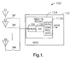
- an exemplary receiver system 100 which includes a plurality of antennas A1, A2 through AN, which are coupled to a single analog front-end 106 (of an FM receiver 104 incorporated within a radio 102) by a different one of a plurality of switches SW1, SW2 through SWN.
- the output of the front-end 106 is provided to an input of an analog-to-digital converter (ADC) 108, which converts the received analog signal to a digital signal.
- ADC analog-to-digital converter
- An output of the ADC 108 is coupled to an input of a digital signal processor (DSP) 110A, which digitally processes the digital signal to provide an audio signal.
- DSP digital signal processor
- an FM demodulator (not shown separately in Fig. 1) outputs an MPX signal, which is directed to the DSP 110A, which implements a switched antenna diversity routine 150 (see Fig. 4).
- the routine 150 improves FM reception by reducing multipath distortion by choosing a least distorted antenna signal from one of a plurality of antennas.
- switched antenna diversity is generally the simplest algorithm to implement among antenna diversity systems. In essence, the switched antenna diversity system selects the antenna with the best signal-to-noise ratio (SNR). However, because only one antenna can truly be selected at a time, the diversity algorithm must generally make the antenna selection based on incomplete knowledge.
- Fig. 2A depicts an FM receiver system 180 that implements a classic switched diversity system using a fast distortion detector 160 that detects spikes, in an FM demodulator output (MPX) signal provided by an FM receiver 104A, with a spike filter 162.
- the detector 160 also detects negative dips, in a received RF level signal, with a dip filter 164.
- the outputs of the spike filter 162 and dip filter 164 are provided to threshold comparators 166A and 166B, respectively.
- Outputs of the threshold comparators 166A and 166B are provided to inputs of a decision logic block 168, which determines when an antenna switch 107 should be switched to another antenna, i.e., a next one of the antennas A1, A2, A3 and A4.
- the logic 168 causes a next antenna to be selected when a spike is detected in the MPX signal coincident with a negative dip in the RF level signal, i.e., when the occurrence of spikes and dips are correlated.
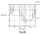
- a graph 200 includes an exemplary RF level signal 202 and an exemplary FM demodulator output (MPX) signal 204.
- MPX FM demodulator output
- the system 180 may increase antenna switching erroneously, which tends to cause audible switching noise in an audio signal. As such, the system 180 may fail to settle on an appropriate antenna, i.e., 'thrash' between antennas or select an antenna that does not provide the best received signal.
- a receiver system 190 includes an FM receiver 104A, whose output is coupled to an input of a slow distortion detector 170.
- the detector 170 may be implemented in hardware or software.
- the detector 170 includes a filter 172, which may be, for example, a bandpass filter that passes frequencies between about 60 kHz and 100 kHz.
- the detector 170 provides an indication of signal quality for weak RF signals, long delay multipath or adjacent channel interference.
- the RF signal is weak (or in the presence of adjacent channel interference)
- high-frequency components 302 appear in the FM baseband spectrum, as is shown in graph 300 of Fig. 3A.
- the slow distortion detector 170 averages energy of the components 302, with a relatively long-time constant, to provide an indication of the received signal quality.
- the high-frequency components can be thought of as ultrasonic noise (USN).
- an output of the filter 172 may be rectified and low-pass filtered by DSP routines.
- higher noise levels associated with weak signal reception
- a receiver system 400 configured according to one embodiment of the present invention, exhibits robust operation over a full dynamic range of a received signal.
- the digitized signal output of the ADC 108 represents the pre-detected FM signal.
- the FM demodulator 110 performs FM detection on this signal to recover the FM multiplex (MPX) signal.
- the ADC signal is also level detected (AM detected) by the RF level detector 112 to obtain the received signal strength, referred to as Level.
- Stereo decoding and de-emphasis of the MPX signal is performed by audio processor 114 to recover the left and right audio signals.
- Multipath disturbances are generally manifested as distortion of the MPX signal, and dynamic variations (AC component) of the Level signal that is otherwise essentially constant for FM.
- the distortion of the MPX signal results in a distortion of the recovered audio.
- the audio processor 114 may employ techniques to suppress or conceal audio distortion, the function of the antenna diversity system is to minimize distortion of the MPX signal, which correspondingly minimizes audio distortion.
- the level average calculation block 403 averages the Level signal (using approximately a 6mS time constant) to provide an update of LevelA(n) for the currently selected antenna.
- an overall average calculation block 402 is produced by averaging the LevelA(n) signals across all antennas to provide a LevelC signal.
- the LevelC signal is then used by a decay ⁇ H calculation block 410 to determine a decay time ⁇ H for an event trigger threshold and an average T A calculation block 408 to provide an averaging time T A for the quality measurement (see Figs. 5A and 5B).
- An event trigger is provided by an event trigger function block 414 and is based on an implementation of a fast distortion detector that correlates between RF level dip and an MPX signal spike, as shown in Fig. 2B.
- An event threshold provided by a threshold function calculation block 412 is introduced to slow down antenna switching, to minimize audible disturbance ("thrashing"), when excessive events, which are more frequent with weak RF signals, occur.
- the event trigger initiates a search for a less distorted (better quality) antenna signal, which then becomes the new favored (reference) antenna.
- the threshold calculation is based on prior antenna event levels that triggered the search, which provides desensitization to reduce switching. This threshold decays at a rate provided by an average decay rate function block 410 that is determined from the combined average RF level, LevelC. A slower decay (longer desensitization) is used at weak signal levels where distortion events are expected to occur more frequently.
- a quality measure function block 406 derives a received signal quality, based on the MPX and RF level signals.
- the quality measure may include signal strength (DC or low-frequency components), AM level (AC or high-frequency components) and ultrasonic noise (USN), i.e., energy beyond the known MPX bandwidth.
- a quick determination of signal quality is desirable with the switched antenna system to minimize the time possibly connected to a poor antenna. However, a sufficient averaging time is needed for a confident measurement.
- the quality measurement averaging time is based on the combined RF level, LevelC, provided by the overall average calculation function block 402. It should be appreciated that lower RF levels require longer averaging time to obtain reliable quality statistics, due to more noise.
- the decision logic function block 404 compares the quality statistics of the trial antenna (currently connected antenna) to that of the reference antenna (i.e., the reference antenna, before the search was trigged by the event trigger). The search terminates when the system 400 finds an antenna signal with better quality than the reference antenna. This selected antenna becomes the new reference antenna. By performing the quality comparison to accept a new antenna, an antenna is chosen which is less likely to encounter distortion events that would lead to another antenna search.
- the decision logic block 404 selects trial antennas (other than the currently favored) in order of larger LevelA(n) signals recorded at the time of the triggering event. Since a larger signal level is more likely to provide better quality, a new favored antenna can be found with a minimum of antenna switching and less chance of trying a poor antenna. Reselecting the presently favored antenna, only after all other antennas have been tried, prevents exclusion of antennas from the search.
- the system 400 utilizes short-term statistics (events) of the received signal, as detected by a fast distortion detector, to trigger a search for an antenna with a signal having better long-term statistics (quality) as detected by a slow distortion detector.
- a threshold is introduced to desensitize the fast distortion detector.
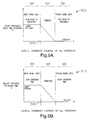
- the threshold attacks on a triggering event value and then decays at a rate (Fig. 5A) that ranges from about 100mS for signal strengths less than an RF level reference (e.g., a 5 ⁇ V level) to about 25 ⁇ S for strong signals.
- the averaging time used with the slow distortion detector transitions from about 500 ⁇ S for signal strengths less than the RF level reference 506 to about 25 ⁇ S for strong signals.
- the operation modes include a transition region 508 that is located between a strong signal mode 502 and a weak signal mode 504.
- the RF level reference 506 e.g., a 5 ⁇ V level
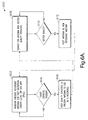
- an exemplary antenna switching routine 600 implemented according to one embodiment of the present invention, is depicted.
- the DSP 110A (implementing routine 150) monitors a present reference antenna for fast distortion events (i.e., a dip in an RF level signal and an MPX signal spike).
- the DSP 110A determines whether an event trigger has occurred. If an event trigger has occurred, control transfers to step 606. Otherwise, control returns from step 604 to step 602.
- the DSP 110A stores the quality statistics of the present antenna, to use as a reference.
- the DSP 110A searches for an antenna with better quality statistics.
- step 610 the DSP 110A determines whether an antenna with better quality has been located. If so, control transfers to step 612, where the antenna with better signal quality becomes the reference antenna, at which point control transfers to step 602. If an antenna with better signal quality is not located in step 610, control returns to step 608, where the DSP 110A continues to search for an antenna with quality statistics that are better than the current reference antenna.
- steps 602A and 630 receive an MPX signal value and steps 602A, 630 and 620 receive an RF level signal value.
- the step 602A represents a routine that monitors a present reference antenna for distortion events, which are indicated when an event threshold, provided in step 626, is exceeded.
- decision step 604A when an event trigger occurs, control transfers to step 606A, where a quality measure of the present reference antenna is stored.
- step 608A a trial antenna is selected.
- step 609 the quality of a signal received by the trial antenna is compared to the quality of a signal received by the current reference antenna.
- decision step 610A it is determined whether the quality of the signal received by the trial antenna is better than that of the current reference antenna. If the quality of the signal provided by the trial antenna is better, the trial antenna becomes the new reference antenna in step 612A and control returns to step 602A. If the quality of the signal provided by the trial antenna is not better than that of the signal provided by the current reference antenna in step 610A, control transfers to decision step 611. In step 611, it is determined whether the quality of the signal provided by the trial antenna is better than the quality of the signal provided by the current reference antenna. If so, control transfers to step 612A, where the trial antenna becomes the new reference antenna. Otherwise, control transfers to step 608A, where a next trial antenna is selected.
- the quality of the signals received by the antennas is determined by a quality measure calculation in step 630.
- the average level for a current antenna is determined by a calculation in step 620.
- the average level is provided to another calculation in step 622, which combines the average level of all antennas to provide a combined average of all antennas signal 'LevelC'.
- the LevelC signal value is used in step 624 to calculate an event threshold decay time ⁇ H , which is used in step 626 to calculate the event threshold.
- the LevelC signal is also used in step 628 to calculate an averaging time T A , which is used in step 630 to calculate a quality measure.
Landscapes
- Engineering & Computer Science (AREA)
- Computer Networks & Wireless Communication (AREA)
- Signal Processing (AREA)
- Physics & Mathematics (AREA)
- Electromagnetism (AREA)
- Quality & Reliability (AREA)
- Radio Transmission System (AREA)
- Noise Elimination (AREA)
Abstract
Description
- The present invention is generally directed to a receiver and, more specifically, to a technique for reducing multipath distortion in a mobile FM receiver having a single analog front-end.
- As is well known, multipath interference is caused when two or more signal rays of an original transmitted signal converge upon a receiving antenna of a receiver at significantly different times. This misalignment or superposition of several delayed signals, which are replicas of the original signal, may cause distortion in audio recovered from the signals. Distortion caused by the multipath interference may be attributable to long delay (e.g., greater than five microseconds between signals) multipath interference or short delay (e.g., less than five microseconds between signals) multipath interference.
- In a typical urban environment, RF signals experience changes in amplitude and phase due to short delay multipath. This amplitude and phase shift may result in broadband signal fades of up to 40 dB, as the receiver and its associated motor vehicle change locations. At typical highway speeds, signal fluctuation rates in the range of 100 to 1 kHz may occur. In general, long delay multipath (or frequency selective multipath) is found in areas where reflectors are greater than four to five miles away. Typically, long delay multipath occurs in cities with large buildings and in mountainous regions.
- Typically, long and short delay multipath coexists and creates frequency selectivity and broadband fading, simultaneously. For example, an FM demodulated signal may contain a 1 kHz tone with a 75 kHz deviation. In such a situation, a reflected signal may have an amplitude of, for example, 0.9 units while a direct signal has, for example, an amplitude of 1 units. In the case where the time delay of the reflected signal is about 30 microseconds, the distortion attributable to the time delay may be on the order of approximately twelve percent.
- In various receiver systems, antenna diversity has been implemented in conjunction with an FM receiver to reduce degraded reception performance caused by multipath interference. Antenna diversity has been accomplished through the use of two or more uncorrelated antennas. Prior art antenna diversity reception for mobile communication systems has been achieved by a number of different implementations. For example, antenna diversity has been accomplished with equal gain combiner (EGC) systems, maximal ratio combiner (MRC) systems and antenna diversity systems, such as the adaptive reception system (ARS) disclosed in
U.S. Patent No. 5,517,686 , the disclosure of which is hereby incorporated herein by reference in its entirety. - EGC and MRC systems utilize signals from all antennas through a variety of combining techniques that attempt to optimize certain characteristics of the received signal. In a switched antenna diversity system, only one antenna is utilized for reception at any instant in time and, thus, the non-selected antennas do not contribute to the demodulated signal. EGC and MRC systems generally outperform switched antenna diversity systems. However, EGC and MRC systems tend to be more expensive to implement, as they require multiple receiver analog front-ends.
- What is needed is an economical technique for further reducing multipath distortion in a mobile FM receiver having a single analog front-end.
- One embodiment of the present invention is directed to a technique for reducing multipath distortion in an FM receiver, with a plurality of switchable antennas. The technique includes providing a fast distortion detector that monitors a received signal for distortion events less than about fifteen microseconds in duration, which indicates a multipath disturbance. A slow distortion detector is also provided that measures distortions of the received signal related to the signal quality. In response to a multipath disturbance, an output of the fast distortion detector initiates a search for a lower distortion (better quality) antenna. The search involves selecting a trial antenna and comparing its measured signal quality (provided by an output of the slow distortion detector) to that previously measured for the antenna that initiated the search (i.e., a reference antenna). An antenna having better signal quality is accepted for continued use and the search is ended. An antenna having a worse signal quality is rejected and the search is continued by selecting another trial antenna.
- To prevent frequent searches that can result in audible switching noise, a threshold is introduced that desensitizes the fast distortion detector for a period following an antenna search. The threshold is decayed at a rate dependent on the overall RF signal level to provide a longer desensitized period for weak signals, which are more susceptible to disturbances. The slow distortion detector uses an averaging time that is a function of the received overall RF signal level, since, in weak signal conditions, the distortion being measured is more corrupted by noise. The averaging time may typically range between twenty-five microseconds for large signal levels to five hundred microseconds when the overall RF signal level is below a predetermined RF level. Antennas are ranked for trial selection based on their recently measured RF level. This approach helps to minimize antenna switching since an antenna having a larger signal level, which is more likely to be lower in distortion, is selected as the next trial antenna.
- The slow distortion detector may implement a filter that passes frequency components of the received RF signal that are higher than about 60 kHz. According to another aspect of this embodiment of the present invention, the filter passes frequency components of the received RF signal that are less than about 100 kHz. According to one aspect of the present invention, the slow distortion detector implements a rectifier and a low-pass filter. In at least one embodiment, the slow distortion detector functions as an ultra sonic noise (USN) detector.
- These and other features, advantages and objects of the present invention will be further understood and appreciated by those skilled in the art by reference to the following specification, claims and appended drawings.
- The present invention will now be described, by way of example, with reference to the accompanying drawings, in which:
- Fig. 1 is a block diagram of an exemplary radio with a single analog front-end and a digital signal processor (DSP);
- Fig. 2A is a block diagram of a receiver system implementing a classic switched diversity system;
- Fig. 2B is a graph depicting an RF signal level and an FM demodulator output signal (MPX) for the receiver system of Fig. 2A;
- Fig. 3A is an exemplary graph of an FM baseband spectrum for an FM receiver;
- Fig. 3B is a block diagram of a relevant portion of an FM receiver system, including a slow distortion detector for detecting high-frequency components in the signals of the graph of Fig. 3A;
- Fig. 4 is a system block diagram for an FM receiver implementing switched diversity, according to one embodiment of the present invention;
- Figs. 5A-5B are graphs depicting regions of operation for the system of Fig. 4;
- Fig. 6A is a high-level flow chart of an exemplary process for reducing multipath distortion in an FM receiver, with a plurality of switchable antennas, according to one embodiment of the present invention; and
- Fig. 6B is a lower-level flow chart of an exemplary process for reducing multipath distortion in an FM receiver, with a plurality of switchable antennas, according to another embodiment of the present invention.
- Today, manufacturers of automotive radios have moved from analog receiver systems to receiver systems that have increasingly incorporated more digital components within the receiver systems. As a general rule, the functions that are performed by these digital components are being increasingly implemented in digital signal processing (DSP) software.
- With reference to Fig. 1, an
exemplary receiver system 100 is shown, which includes a plurality of antennas A1, A2 through AN, which are coupled to a single analog front-end 106 (of anFM receiver 104 incorporated within a radio 102) by a different one of a plurality of switches SW1, SW2 through SWN. The output of the front-end 106 is provided to an input of an analog-to-digital converter (ADC) 108, which converts the received analog signal to a digital signal. An output of theADC 108 is coupled to an input of a digital signal processor (DSP) 110A, which digitally processes the digital signal to provide an audio signal. - According to one aspect of the present invention, as is discussed further below, software algorithms (see Figs. 6A-6B) executed by a DSP implement switched antenna diversity for the
receiver system 100. According to another aspect of the present invention, an FM demodulator (not shown separately in Fig. 1) outputs an MPX signal, which is directed to theDSP 110A, which implements a switched antenna diversity routine 150 (see Fig. 4). In general, the routine 150 improves FM reception by reducing multipath distortion by choosing a least distorted antenna signal from one of a plurality of antennas. As noted above, switched antenna diversity is generally the simplest algorithm to implement among antenna diversity systems. In essence, the switched antenna diversity system selects the antenna with the best signal-to-noise ratio (SNR). However, because only one antenna can truly be selected at a time, the diversity algorithm must generally make the antenna selection based on incomplete knowledge. - Fig. 2A depicts an
FM receiver system 180 that implements a classic switched diversity system using afast distortion detector 160 that detects spikes, in an FM demodulator output (MPX) signal provided by anFM receiver 104A, with aspike filter 162. Thedetector 160 also detects negative dips, in a received RF level signal, with adip filter 164. The outputs of thespike filter 162 anddip filter 164 are provided tothreshold comparators threshold comparators decision logic block 168, which determines when anantenna switch 107 should be switched to another antenna, i.e., a next one of the antennas A1, A2, A3 and A4. In general, thelogic 168 causes a next antenna to be selected when a spike is detected in the MPX signal coincident with a negative dip in the RF level signal, i.e., when the occurrence of spikes and dips are correlated. - With reference to Fig. 2B, a
graph 200 includes an exemplaryRF level signal 202 and an exemplary FM demodulator output (MPX)signal 204. As theRF signal level 202 becomes weaker (decreases in magnitude), the received SNR degrades and the spike and dip detection may be corrupted by noise. In this case, thesystem 180 may increase antenna switching erroneously, which tends to cause audible switching noise in an audio signal. As such, thesystem 180 may fail to settle on an appropriate antenna, i.e., 'thrash' between antennas or select an antenna that does not provide the best received signal. - With reference to Fig. 3B, a
receiver system 190 includes anFM receiver 104A, whose output is coupled to an input of a slow distortion detector 170. It should be appreciated that the detector 170 may be implemented in hardware or software. The detector 170 includes afilter 172, which may be, for example, a bandpass filter that passes frequencies between about 60 kHz and 100 kHz. In general, the detector 170 provides an indication of signal quality for weak RF signals, long delay multipath or adjacent channel interference. When the RF signal is weak (or in the presence of adjacent channel interference), high-frequency components 302 appear in the FM baseband spectrum, as is shown ingraph 300 of Fig. 3A. - The slow distortion detector 170 averages energy of the
components 302, with a relatively long-time constant, to provide an indication of the received signal quality. The less high-frequency component energy present, the better the antenna signal quality. In general, the high-frequency components can be thought of as ultrasonic noise (USN). With reference again to Fig. 3B, an output of thefilter 172 may be rectified and low-pass filtered by DSP routines. According to one aspect of the present invention, higher noise levels (associated with weak signal reception) require longer time averaging for reliable statistics. This, in turn, reduces both 'thrashing' among antennas and poor antenna selection under weak signal conditions. - With reference to Fig. 4, a
receiver system 400, configured according to one embodiment of the present invention, exhibits robust operation over a full dynamic range of a received signal. In this embodiment, implemented, for example, in software, the digitized signal output of theADC 108 represents the pre-detected FM signal. The FM demodulator 110 performs FM detection on this signal to recover the FM multiplex (MPX) signal. The ADC signal is also level detected (AM detected) by theRF level detector 112 to obtain the received signal strength, referred to as Level. Stereo decoding and de-emphasis of the MPX signal is performed byaudio processor 114 to recover the left and right audio signals. Multipath disturbances are generally manifested as distortion of the MPX signal, and dynamic variations (AC component) of the Level signal that is otherwise essentially constant for FM. The distortion of the MPX signal results in a distortion of the recovered audio. Though theaudio processor 114 may employ techniques to suppress or conceal audio distortion, the function of the antenna diversity system is to minimize distortion of the MPX signal, which correspondingly minimizes audio distortion. - A separate level
average calculation block 403, LevelA(n), is maintained for each antenna (n=1 to N) as a measure of its average received signal strength. The levelaverage calculation block 403 averages the Level signal (using approximately a 6mS time constant) to provide an update of LevelA(n) for the currently selected antenna. As a measure of the overall received signal strength, an overallaverage calculation block 402 is produced by averaging the LevelA(n) signals across all antennas to provide a LevelC signal. The LevelC signal is then used by a decay τHcalculation block 410 to determine a decay time τH for an event trigger thresholdand an average TA calculation block 408 to provide an averaging time TA for the quality measurement (see Figs. 5A and 5B).
- An event trigger is provided by an event trigger function block 414 and is based on an implementation of a fast distortion detector that correlates between RF level dip and an MPX signal spike, as shown in Fig. 2B. An event threshold provided by a threshold
function calculation block 412 is introduced to slow down antenna switching, to minimize audible disturbance ("thrashing"), when excessive events, which are more frequent with weak RF signals, occur. The event trigger initiates a search for a less distorted (better quality) antenna signal, which then becomes the new favored (reference) antenna. The threshold calculation is based on prior antenna event levels that triggered the search, which provides desensitization to reduce switching. This threshold decays at a rate provided by an average decayrate function block 410 that is determined from the combined average RF level, LevelC. A slower decay (longer desensitization) is used at weak signal levels where distortion events are expected to occur more frequently. - A quality
measure function block 406 derives a received signal quality, based on the MPX and RF level signals. The quality measure may include signal strength (DC or low-frequency components), AM level (AC or high-frequency components) and ultrasonic noise (USN), i.e., energy beyond the known MPX bandwidth. A quick determination of signal quality is desirable with the switched antenna system to minimize the time possibly connected to a poor antenna. However, a sufficient averaging time is needed for a confident measurement. The quality measurement averaging time is based on the combined RF level, LevelC, provided by the overall averagecalculation function block 402. It should be appreciated that lower RF levels require longer averaging time to obtain reliable quality statistics, due to more noise. - The decision
logic function block 404 compares the quality statistics of the trial antenna (currently connected antenna) to that of the reference antenna (i.e., the reference antenna, before the search was trigged by the event trigger). The search terminates when thesystem 400 finds an antenna signal with better quality than the reference antenna. This selected antenna becomes the new reference antenna. By performing the quality comparison to accept a new antenna, an antenna is chosen which is less likely to encounter distortion events that would lead to another antenna search. - Switching between antennas creates some disturbance in the detected audio as a result of discontinuity between received antenna signals and from selecting an antenna with a poor signal quality. To minimize the audible disturbance, the
decision logic block 404 selects trial antennas (other than the currently favored) in order of larger LevelA(n) signals recorded at the time of the triggering event. Since a larger signal level is more likely to provide better quality, a new favored antenna can be found with a minimum of antenna switching and less chance of trying a poor antenna. Reselecting the presently favored antenna, only after all other antennas have been tried, prevents exclusion of antennas from the search. - The
system 400 utilizes short-term statistics (events) of the received signal, as detected by a fast distortion detector, to trigger a search for an antenna with a signal having better long-term statistics (quality) as detected by a slow distortion detector. To prevent frequent antenna searches from causing an audible disturbance, a threshold is introduced to desensitize the fast distortion detector. The threshold attacks on a triggering event value and then decays at a rate (Fig. 5A) that ranges from about 100mS for signal strengths less than an RF level reference (e.g., a 5µV level) to about 25µS for strong signals. To maintain confidence in the long-term statistics, the averaging time used with the slow distortion detector (Fig. 5B) transitions from about 500µS for signal strengths less than theRF level reference 506 to about 25µS for strong signals. - With reference to Figs. 5A and 5B, these operation modes are further depicted in
graphs transition region 508 that is located between astrong signal mode 502 and aweak signal mode 504. The RF level reference 506 (e.g., a 5µV level) defines a point where the operation mode transitions between thestrong signal mode 502 and theweak signal mode 504. - With reference to Fig. 6, an exemplary antenna switching routine 600, implemented according to one embodiment of the present invention, is depicted. In
step 602, theDSP 110A (implementing routine 150) monitors a present reference antenna for fast distortion events (i.e., a dip in an RF level signal and an MPX signal spike). Next, indecision step 604, theDSP 110A determines whether an event trigger has occurred. If an event trigger has occurred, control transfers to step 606. Otherwise, control returns fromstep 604 to step 602. Instep 606, theDSP 110A stores the quality statistics of the present antenna, to use as a reference. Next, instep 608, theDSP 110A searches for an antenna with better quality statistics. Then, indecision step 610, theDSP 110A determines whether an antenna with better quality has been located. If so, control transfers to step 612, where the antenna with better signal quality becomes the reference antenna, at which point control transfers to step 602. If an antenna with better signal quality is not located instep 610, control returns to step 608, where theDSP 110A continues to search for an antenna with quality statistics that are better than the current reference antenna. - With reference to Fig. 6B, a routine 600A is depicted that provides a more detailed process flow for implementing various embodiments of the present invention. As is shown, steps 602A and 630 receive an MPX signal value and steps 602A, 630 and 620 receive an RF level signal value. The
step 602A represents a routine that monitors a present reference antenna for distortion events, which are indicated when an event threshold, provided instep 626, is exceeded. Indecision step 604A, when an event trigger occurs, control transfers to step 606A, where a quality measure of the present reference antenna is stored. Next, instep 608A, a trial antenna is selected. - Then, in
step 609, the quality of a signal received by the trial antenna is compared to the quality of a signal received by the current reference antenna. Next, indecision step 610A, it is determined whether the quality of the signal received by the trial antenna is better than that of the current reference antenna. If the quality of the signal provided by the trial antenna is better, the trial antenna becomes the new reference antenna instep 612A and control returns to step 602A. If the quality of the signal provided by the trial antenna is not better than that of the signal provided by the current reference antenna instep 610A, control transfers todecision step 611. Instep 611, it is determined whether the quality of the signal provided by the trial antenna is better than the quality of the signal provided by the current reference antenna. If so, control transfers to step 612A, where the trial antenna becomes the new reference antenna. Otherwise, control transfers to step 608A, where a next trial antenna is selected. - The quality of the signals received by the antennas is determined by a quality measure calculation in
step 630. The average level for a current antenna is determined by a calculation instep 620. The average level is provided to another calculation instep 622, which combines the average level of all antennas to provide a combined average of all antennas signal 'LevelC'. The LevelC signal value is used instep 624 to calculate an event threshold decay time τH, which is used instep 626 to calculate the event threshold. The LevelC signal is also used instep 628 to calculate an averaging time TA, which is used instep 630 to calculate a quality measure. - The above description is considered that of the preferred embodiments only. Modifications of the invention will occur to those skilled in the art and to those who make or use the invention. Therefore, it is understood that the embodiments shown in the drawings and described above are merely for illustrative purposes and not intended to limit the scope of the invention, which is defined by the following claims as interpreted according to the principles of patent law, including the doctrine of equivalents.
Claims (18)
- A method (150) for reducing multipath distortion in an FM receiver with a plurality of switchable antennas, comprising the steps of:providing a fast distortion detector (414), wherein the fast distortion detector monitors a received signal for distortion events less than about fifteen microseconds in duration;providing a slow distortion detector (406), wherein the slow distortion detector measures distortions relating to quality of the received signal;triggering an antenna search based upon an output of the fast distortion detector (414);selecting a trial antenna based upon average signal levels measured on each of a plurality of antennas (403); andmaintaining a present trial antenna as a reference antenna or selecting another trial antenna based upon a quality comparison of an output of the slow distortion detector (404).
- The method (150) of claim 1, wherein the slow distortion detector (406) implements a filter that passes frequency components of the received RF signal that are higher than about 60 kHz.
- The method (150) of claim 2, wherein the filter passes frequency components of the received RF signal that are less than about 100 kHz.
- The method (150) of claim 3, wherein the slow distortion detector (406) rectifies the received RF signal.
- The method (150) of claim 1, wherein the slow distortion detector (406) functions as an ultra sonic noise (USN) detector.
- The method (150) of claim 3, wherein the slow distortion detector (406) functions as an ultra sonic noise (USN) detector.
- A method (150) for reducing multipath distortion in an FM receiver with a plurality of switchable antennas, comprising the steps of:providing a fast distortion detector (414), wherein the fast distortion detector triggers a search for a different one of a plurality of switchable antennas when a received RF signal simultaneously exhibits a spike in an FM demodulator output and a negative dip in an RF signal level, and wherein the fast distortion detector monitors the received RF signal for distortion events less than about fifteen microseconds in duration; andproviding a slow distortion detector (406), wherein the slow distortion detector uses an averaging time that varies between twenty-five microseconds and five-hundred microseconds dependent on the received RF signal level.
- The method (150) of claim 7, wherein the slow distortion detector (406) implements a filter that passes frequency components of the received RF signal that are higher than about 60 kHz.
- The method (150) of claim 8, wherein the filter passes frequency components of the received RF signal that are less than about 100 kHz.
- The method (150) of claim 7, wherein the slow distortion detector (406) implements a rectifier.
- The method (150) of claim 7, wherein the slow distortion detector (406) functions as an ultra sonic noise (USN) detector.
- The method (150) of claim 7, wherein the predetermined signal quality level corresponds to a maximum ultra sonic noise (USN) level.
- An FM receiver (400), comprising:a front-end (106) coupled to a plurality of antennas (A1,A2,AN), wherein each of the antennas (A1,A2,AN) is coupled to an input of the front-end (106) by a different one of a plurality of switches (SW1, SW2,SWN);an analog-to-digital converter (ADC) (108) with an input coupled to an output of the front-end (106);an FM demodulator (110) having an input coupled to an output of the ADC (108);a fast distortion detector (414) with an input coupled to an output of the FM demodulator (110), wherein the fast distortion detector (414) initiates a search for a lower distortion antenna when a received RF signal substantially simultaneously exhibits a spike in an output of the FM demodulator (110) and a negative dip in an RF signal level of the received RF signal that exceeds an event threshold (412), and wherein an event threshold decay (410) is controlled by an overall RF level; anda slow distortion detector (406), wherein the slow distortion detector (406) measures distortions of the received RF signal relating to signal quality, wherein the slow distortion detector (406) uses an averaging time that is a function of the overall RF signal level and that ranges between twenty-five microseconds to five-hundred microseconds when the overall RF signal level is below a predetermined RF level.
- The receiver (400) of claim 13, wherein the slow distortion detector (406) implements a filter that passes frequency components of the received RF signal that are higher than about 60 kHz.
- The receiver (400) of claim 14, wherein the slow distortion detector (406) implements a filter that passes frequency components of the received RF signal that are less than about 100 kHz.
- The receiver (400) of claim 13, wherein the slow distortion detector (406) implements a rectifier.
- The receiver (400) of claim 13, wherein the slow distortion detector (406) acts as an ultra sonic noise (USN) detector.
- The receiver (400) of claim 13, wherein the predetermined signal quality level corresponds to a maximum ultra sonic noise (USN) level.
Applications Claiming Priority (1)
| Application Number | Priority Date | Filing Date | Title |
|---|---|---|---|
| US11/201,883 US7590399B2 (en) | 2005-08-11 | 2005-08-11 | Technique for reducing multipath interference in an FM receiver |
Publications (2)
| Publication Number | Publication Date |
|---|---|
| EP1753155A2 true EP1753155A2 (en) | 2007-02-14 |
| EP1753155A3 EP1753155A3 (en) | 2013-08-28 |
Family
ID=37488135
Family Applications (1)
| Application Number | Title | Priority Date | Filing Date |
|---|---|---|---|
| EP06076349.7A Withdrawn EP1753155A3 (en) | 2005-08-11 | 2006-07-03 | Technique for reducing multipath interference in an FM receiver |
Country Status (2)
| Country | Link |
|---|---|
| US (1) | US7590399B2 (en) |
| EP (1) | EP1753155A3 (en) |
Cited By (3)
| Publication number | Priority date | Publication date | Assignee | Title |
|---|---|---|---|---|
| EP1848118A3 (en) * | 2006-04-20 | 2010-04-14 | Delphi Technologies, Inc. | RF receiver system having switching antenna diversity module |
| CN109474299A (en) * | 2018-10-18 | 2019-03-15 | 维沃移动通信有限公司 | A kind of antenna determination method and mobile terminal |
| FR3131149A1 (en) * | 2021-12-21 | 2023-06-23 | Thales | METHOD FOR PROCESSING A FREQUENCY MODULATED ANALOG SIGNAL IN A WIRELESS COMMUNICATION RECEIVER, COMPUTER PROGRAM AND ASSOCIATED WIRELESS COMMUNICATION RECEIVER. |
Families Citing this family (12)
| Publication number | Priority date | Publication date | Assignee | Title |
|---|---|---|---|---|
| US7499691B1 (en) * | 2005-11-29 | 2009-03-03 | Kyocera Wireless Corp. | Systems and methods for selecting an antenna configuration in a mobile communication device |
| JP5000936B2 (en) * | 2006-06-27 | 2012-08-15 | オンセミコンダクター・トレーディング・リミテッド | Multipath noise detector and FM receiver |
| WO2009008114A1 (en) * | 2007-07-09 | 2009-01-15 | Mitsubishi Electric Corporation | Radio receiver and method of filtering noise in the receiver |
| US20090252204A1 (en) * | 2008-04-04 | 2009-10-08 | Delphi Technologies, Inc. | Receiver system for receiving analog and digital signals |
| KR101589607B1 (en) * | 2009-03-02 | 2016-01-29 | 삼성전자주식회사 | Communication system having femto base station and communication terminal and communication method therefor |
| KR101141429B1 (en) * | 2009-12-03 | 2012-05-03 | 삼성전기주식회사 | Apparatus and method for selecting antenna of diversity antenna system |
| US8634766B2 (en) | 2010-02-16 | 2014-01-21 | Andrew Llc | Gain measurement and monitoring for wireless communication systems |
| CN105452891B (en) | 2013-08-15 | 2019-09-27 | 皇家飞利浦有限公司 | Patient monitoring involving the use of antenna diversity to receive multiple asynchronous data streams |
| FR3070796B1 (en) * | 2017-09-05 | 2019-08-30 | Continental Automotive France | METHOD FOR UPDATING A LIST OF STATIONS RECEIVABLE BY A RADIO RECEIVING SYSTEM |
| US10840995B1 (en) * | 2019-11-04 | 2020-11-17 | Qualcomm Incorporated | Diversity techniques in true wireless stereo (TWS) shadowing |
| US11190386B2 (en) * | 2020-04-22 | 2021-11-30 | Nxp B.V. | Smart adjacent-channel indicating/scanning for FM modulation |
| CN111835368B (en) * | 2020-07-31 | 2022-11-18 | 海能达通信股份有限公司 | Zero intermediate frequency receiving system |
Family Cites Families (12)
| Publication number | Priority date | Publication date | Assignee | Title |
|---|---|---|---|---|
| US4566133A (en) * | 1982-12-27 | 1986-01-21 | Commtech International | Switched diversity method and apparatus for FM receivers |
| NL8502695A (en) * | 1985-10-02 | 1987-05-04 | Philips Nv | RECEIVER FITTED WITH A MULTI-PATH DETECTOR. |
| US5446922A (en) * | 1992-12-21 | 1995-08-29 | Motorola, Inc. | Method and apparatus for switched diversity reception of a radio signal |
| US5517686A (en) | 1994-09-29 | 1996-05-14 | Delco Electronics Corporation | Diversity receiver for FM stereo utilizing a pilot tone multiple for phase alignment of received signals |
| KR100590428B1 (en) * | 1994-10-17 | 2006-09-20 | 코닌클리케 필립스 일렉트로닉스 엔.브이. | Wireless digital communication systems, digital wireless devices and digital speakers |
| US5603107A (en) * | 1995-06-09 | 1997-02-11 | Ford Motor Company | Switching system for diversity antenna FM receiver |
| SE9702370L (en) * | 1997-06-19 | 1998-12-20 | Ericsson Telefon Ab L M | Balanced diversity |
| DE60030954T2 (en) * | 2000-04-25 | 2007-02-01 | Siemens Ag | Receiver with antenna diversity |
| DE60029303T2 (en) * | 2000-04-28 | 2007-07-05 | Siemens Ag | Receiver with antenna diversity |
| JP2003046418A (en) * | 2001-08-03 | 2003-02-14 | Uniden Corp | Diversity receiver |
| DE10304431A1 (en) * | 2003-02-04 | 2004-08-05 | Lindenmeier, Heinz, Prof. Dr.-Ing. | Scanning antenna diversity system is used for frequency modulated audio wireless signals in a road vehicle |
| JP3952404B2 (en) * | 2003-05-19 | 2007-08-01 | ソニー株式会社 | Receiver |
-
2005
- 2005-08-11 US US11/201,883 patent/US7590399B2/en active Active
-
2006
- 2006-07-03 EP EP06076349.7A patent/EP1753155A3/en not_active Withdrawn
Non-Patent Citations (1)
| Title |
|---|
| None * |
Cited By (5)
| Publication number | Priority date | Publication date | Assignee | Title |
|---|---|---|---|---|
| EP1848118A3 (en) * | 2006-04-20 | 2010-04-14 | Delphi Technologies, Inc. | RF receiver system having switching antenna diversity module |
| CN109474299A (en) * | 2018-10-18 | 2019-03-15 | 维沃移动通信有限公司 | A kind of antenna determination method and mobile terminal |
| CN109474299B (en) * | 2018-10-18 | 2020-07-14 | 维沃移动通信有限公司 | Antenna determination method and mobile terminal |
| FR3131149A1 (en) * | 2021-12-21 | 2023-06-23 | Thales | METHOD FOR PROCESSING A FREQUENCY MODULATED ANALOG SIGNAL IN A WIRELESS COMMUNICATION RECEIVER, COMPUTER PROGRAM AND ASSOCIATED WIRELESS COMMUNICATION RECEIVER. |
| EP4203403A1 (en) * | 2021-12-21 | 2023-06-28 | Thales | Method for processing a frequency-modulated analog signal in a wireless communication receiver, associated computer program and wireless communication receiver |
Also Published As
| Publication number | Publication date |
|---|---|
| EP1753155A3 (en) | 2013-08-28 |
| US20070037538A1 (en) | 2007-02-15 |
| US7590399B2 (en) | 2009-09-15 |
Similar Documents
| Publication | Publication Date | Title |
|---|---|---|
| US7590399B2 (en) | Technique for reducing multipath interference in an FM receiver | |
| US7697913B2 (en) | Dual tuner diversity for background processing and to reduce multipath distortion | |
| EP2107640A1 (en) | Receiver system for receiving analog and digital signals | |
| US4752968A (en) | Antenna diversity reception system for eliminating reception interferences | |
| US7127218B2 (en) | Scanning antenna diversity system for FM radio for vehicles | |
| US5548836A (en) | Diversity receiver | |
| EP1120919B1 (en) | Multipath noise reducer, audio output circuit, and FM receiver | |
| EP1848118B1 (en) | Rf receiver system having switching antenna diversity module | |
| US20050245224A1 (en) | Receiver | |
| EP0854589A3 (en) | Adaptive antenna diversity receiver | |
| US5402451A (en) | Digital post-detection FM spatial diversity combination circuit | |
| WO1994013064A1 (en) | Automotive radio employing multipath correction strategy based on vehicle speed | |
| EP2114022A2 (en) | Receiver system and method for receiving signals | |
| US20040142669A1 (en) | Method and device for suppressing multipath interference in a receiver for electromagnetic waves | |
| US4495653A (en) | Diversity receiver | |
| US7400867B2 (en) | Radio broadcast receiver | |
| US6118990A (en) | Receiving apparatus with diversity | |
| JPH07101856B2 (en) | Receiving machine | |
| JPH0771016B2 (en) | Reception interference detector when receiving UHF-FM broadcasting | |
| WO2006106788A1 (en) | Reducing apparatus and method, and receiving apparatus | |
| EP1753156B1 (en) | Method for calculating weights for diversity combining in an FM-receiver | |
| EP2211485A1 (en) | Hybrid switched-phased diversity system and method | |
| US5465404A (en) | Communications receiver with an adaptive squelch system | |
| US20060223477A1 (en) | Receiving apparatus, signal processing circuit, and signal receiving method | |
| WO1999001951A1 (en) | Method and system for rejecting interfering signals |
Legal Events
| Date | Code | Title | Description |
|---|---|---|---|
| PUAI | Public reference made under article 153(3) epc to a published international application that has entered the european phase |
Free format text: ORIGINAL CODE: 0009012 |
|
| AK | Designated contracting states |
Kind code of ref document: A2 Designated state(s): AT BE BG CH CY CZ DE DK EE ES FI FR GB GR HU IE IS IT LI LT LU LV MC NL PL PT RO SE SI SK TR |
|
| AX | Request for extension of the european patent |
Extension state: AL BA HR MK YU |
|
| PUAL | Search report despatched |
Free format text: ORIGINAL CODE: 0009013 |
|
| AK | Designated contracting states |
Kind code of ref document: A3 Designated state(s): AT BE BG CH CY CZ DE DK EE ES FI FR GB GR HU IE IS IT LI LT LU LV MC NL PL PT RO SE SI SK TR |
|
| AX | Request for extension of the european patent |
Extension state: AL BA HR MK RS |
|
| RIC1 | Information provided on ipc code assigned before grant |
Ipc: H04B 17/00 20060101ALI20130724BHEP Ipc: H04B 7/08 20060101AFI20130724BHEP |
|
| 17P | Request for examination filed |
Effective date: 20140228 |
|
| RBV | Designated contracting states (corrected) |
Designated state(s): AT BE BG CH CY CZ DE DK EE ES FI FR GB GR HU IE IS IT LI LT LU LV MC NL PL PT RO SE SI SK TR |
|
| AKX | Designation fees paid |
Designated state(s): AT BE BG CH CY CZ DE DK EE ES FI FR GB GR HU IE IS IT LI LT LU LV MC NL PL PT RO SE SI SK TR |
|
| 17Q | First examination report despatched |
Effective date: 20180209 |
|
| STAA | Information on the status of an ep patent application or granted ep patent |
Free format text: STATUS: THE APPLICATION HAS BEEN WITHDRAWN |
|
| 18W | Application withdrawn |
Effective date: 20180409 |