EP1753108A2 - Method and apparatus for sensing brushless DC motor average current from overcurrent protection circuitry - Google Patents
Method and apparatus for sensing brushless DC motor average current from overcurrent protection circuitry Download PDFInfo
- Publication number
- EP1753108A2 EP1753108A2 EP06016706A EP06016706A EP1753108A2 EP 1753108 A2 EP1753108 A2 EP 1753108A2 EP 06016706 A EP06016706 A EP 06016706A EP 06016706 A EP06016706 A EP 06016706A EP 1753108 A2 EP1753108 A2 EP 1753108A2
- Authority
- EP
- European Patent Office
- Prior art keywords
- duty cycle
- value
- pulses
- signal
- current
- Prior art date
- Legal status (The legal status is an assumption and is not a legal conclusion. Google has not performed a legal analysis and makes no representation as to the accuracy of the status listed.)
- Withdrawn
Links
Images


Classifications
-
- H—ELECTRICITY
- H02—GENERATION; CONVERSION OR DISTRIBUTION OF ELECTRIC POWER
- H02H—EMERGENCY PROTECTIVE CIRCUIT ARRANGEMENTS
- H02H7/00—Emergency protective circuit arrangements specially adapted for specific types of electric machines or apparatus or for sectionalised protection of cable or line systems, and effecting automatic switching in the event of an undesired change from normal working conditions
- H02H7/08—Emergency protective circuit arrangements specially adapted for specific types of electric machines or apparatus or for sectionalised protection of cable or line systems, and effecting automatic switching in the event of an undesired change from normal working conditions for dynamo-electric motors
- H02H7/0833—Emergency protective circuit arrangements specially adapted for specific types of electric machines or apparatus or for sectionalised protection of cable or line systems, and effecting automatic switching in the event of an undesired change from normal working conditions for dynamo-electric motors for electric motors with control arrangements
Definitions
- the present invention relates to a method and apparatus for sensing brushless DC average motor current, and more particularly to a method and apparatus which sense average motor current from overcurrent protection circuitry.
- the motor average current is the average current being drawn from the input power supply by the motor drive system.
- knowledge of the motor average current can be used by the microcontroller for protecting the motor.
- the microcontroller can control the motor such as to limit its average current to a specific maximum value. This maximum value can be derived based on the maximum current rating of the motor.
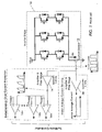
- Figure 1 shows a typical apparatus used for sensing the average motor current in a brushless DC motor drive system 10.
- the dc-link current idc is measured using a current sensor 12.
- this current sensor can be a dc-link shunt resistor, a Hall effect current sensor, etc.
- An amplifier and filter stage 30, with a very heavy filter is used to amplify and filter the dc-link current and obtain the motor average current.
- the resulting motor average current signal can then be sampled by the microcontroller 20 and used for protecting the motor.
- FIG. 1 A typical circuit used to detect instantaneous overcurrent conditions is also shown in Figure 1.
- an amplifier and filter stage 14 with a light filter e.g. 0-20KHz bandwidth
- the output of the amplifier and filter stage is a pulsating voltage that represents the instantaneous dc-link current. This voltage is then presented to multiple comparators 16a, 16b, ..., 16n.
- Each comparator compares the instantaneous dc-link current to a specific threshold that represents an instantaneous current level deemed more or less dangerous. If the output of a comparator switches, then the microcontroller immediately becomes advised of an overcurrent condition. In such case, as a means for protection, the microcontroller turns off all inverter switches for the remainder of the PWM cycle thereby effectively reducing the PWM duty cycle.
- two amplifier and filter stages 14 and 30 are used to condition the de-link current.
- One stage 30 is used to derive the motor average current and the other stage 14 is used for instantaneous dc-link overcurrent protection.
- the invention permits the suppression of the amplifier and filter stage that is typically used to derive the motor average current directly from the dc-link current. The invention thereby provides a significant system cost reduction.
- Fig. 1 is a schematic diagram of a known apparatus for sensing average motor current.
- Fig. 2 is a schematic diagram of an apparatus for sensing average motor current according to an embodiment of the invention.
- Fig. 3 is a diagram illustrating a method for calculating average motor current.
- Fig. 4 is a graph illustrating an example of how a duty value is assigned.
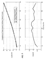
- Fig. 5 is a graph of test results showing a correspondence between power supply current and software filtered current.
- the microcontroller is programmed to sample only the peaks of the dc-link current signal (i.e. the peak values of the output of the amplifier and filter stage 14).
- the filtering of the resulting current samples, and thereby the calculation of the motor average current, is performed in software by the microcontroller 20 using the method described below.
- the outputs of the comparators are routed to interrupt pins of the microcontroller 20. This allows the software to become aware of when, within a PWM cycle, the microcontroller turns off all inverter switches for the remainder of that PWM cycle. As mentioned above, this is typically done in order to protect the power components against instantaneous dc-link overcurrent conditions.
- the current samples resulting from the sampling scheme described above are used to calculate the motor average current. In one example of a calculating method, this can be done by multiplying these samples by the operating PWM duty cycle, before adding filtering and gain/offset correction. This exemplary method is shown in Figure 3.
- the current samples are multiplied by the PWM duty cycle (i.e. the value of Duty in percentage points) before being digitally filtered.
- the filter removes noise and other non-linear effects.
- the filter can be, for example, an infinite impulse response (IIR) filter or a finite impulse response (FIR) filter.
- IIR infinite impulse response
- FIR finite impulse response
- a gain and offset correction is then applied to the output of the filter.
- the gain and offset values are fixed and are obtained via calibration.
- the resulting signal is the motor average current.
- Duty in Figure 3 can originate from two sources. During a PWM cycle, if no instantaneous dc-link overcurrent conditions were detected (i.e. the outputs of the comparators in Figure 2 have not switched), then Duty in Figure 3 is simply equal to the PWM duty cycle used by the software for normal motor commutation. However, if an instantaneous de-link overcurrent condition has been detected (i.e. one or more comparators in Figure 2 have switched), then the value of Duty in Figure 3 is calculated as follows:
- the value of the PWM timer is read by the software. This value is then divided by the PWM timer period. If the resulting quotient is smaller than the software PWM duty cycle used for normal motor commutation, then this resulting quotient is used as the value of Duty in Figure 3. Otherwise, Duty remains equal to the software PWM duty cycle used for normal motor commutation.
- Figure 4 illustrates the manner by which the value of Duty is assigned in the presence of an instantaneous dc-link overcurrent condition.
- Figure 4 illustrates four PWM cycles. In the first two cycles, no instantaneous dc-link overcurrent conditions are detected by the comparators of Figure 2. In such case, the value of Duty in Figure 3 is simply equal to the software PWM duty cycle used for normal motor commutation. In other words, the value of Duty is equal to the software duty cycle compare value divided by the PWM timer period.
- the value of the PWM timer is read and divided by PWMPeriod.
- the result of this division is smaller than the software PWM duty cycle. Therefore, Duty is equal to Vall/PWMPeriod.
- the resulting division is larger than the software PWM duty cycle. Therefore, the value of Duty remains equal to the software PWM duty cycle.
- Figure 5 shows preliminary results of the filtering scheme.
- the power supply current is effectively the actual motor average current.
- the software filtered current is the motor average current obtained from the method and apparatus described above.
Landscapes
- Control Of Motors That Do Not Use Commutators (AREA)
- Amplifiers (AREA)
- Inverter Devices (AREA)
- Measurement Of Current Or Voltage (AREA)
- Emergency Protection Circuit Devices (AREA)
Abstract
Description
- This application is based upon and claims priority of
U.S. Provisional Serial No. 60/706,962 filed August 10, 2005 - It is related to
U.S. Provisional Serial No. 60/706,956 filed August 10, 2005 - The present invention relates to a method and apparatus for sensing brushless DC average motor current, and more particularly to a method and apparatus which sense average motor current from overcurrent protection circuitry.
- In the design of brushless DC motor drive systems, there is often a requirement to sense the motor average current. Effectively, the motor average current is the average current being drawn from the input power supply by the motor drive system. In brushless DC motor drive systems that are employed for safety-critical applications, such as but not restricted to electro-hydraulic power steering systems, knowledge of the motor average current can be used by the microcontroller for protecting the motor. For example, the microcontroller can control the motor such as to limit its average current to a specific maximum value. This maximum value can be derived based on the maximum current rating of the motor.
- Figure 1 shows a typical apparatus used for sensing the average motor current in a brushless DC
motor drive system 10. - In Figure 1, the dc-link current idc is measured using a
current sensor 12. For example, this current sensor can be a dc-link shunt resistor, a Hall effect current sensor, etc. An amplifier andfilter stage 30, with a very heavy filter (e.g. 0-10Hz bandwidth), is used to amplify and filter the dc-link current and obtain the motor average current. The resulting motor average current signal can then be sampled by themicrocontroller 20 and used for protecting the motor. - In brushless DC motor drive systems that are employed for safety-critical applications, such as but not restricted to electro-hydraulic power steering systems, there is often an additional requirement to sense the instantaneous dc-link current and use it for protecting the system power components against overcurrent conditions. A typical circuit used to detect instantaneous overcurrent conditions is also shown in Figure 1. In this case, an amplifier and
filter stage 14 with a light filter (e.g. 0-20KHz bandwidth) appropriately conditions the measured dc-link current. The output of the amplifier and filter stage is a pulsating voltage that represents the instantaneous dc-link current. This voltage is then presented tomultiple comparators - Thus, typically, two amplifier and
filter stages stage 30 is used to derive the motor average current and theother stage 14 is used for instantaneous dc-link overcurrent protection. - The requirement of two amplifier and filter stages for average current sensing and instantaneous dc-link overcurrent protection can be expensive in cost-sensitive applications, such as but not restricted to electro-hydraulic power steering systems.
- Disclosed herein are a method and an apparatus that permit the measurement of the motor average current directly from the output of the amplifier and filter stage used for instantaneous de-link overcurrent protection. As such, only one amplifier and filter stage is used to provide both the motor average current and instantaneous dc-link overcurrent protection. The invention permits the suppression of the amplifier and filter stage that is typically used to derive the motor average current directly from the dc-link current. The invention thereby provides a significant system cost reduction.
- Other features and advantages of the present invention will become apparent from the following description of embodiments of the invention which refers to the accompanying drawings.
- Fig. 1 is a schematic diagram of a known apparatus for sensing average motor current.
- Fig. 2 is a schematic diagram of an apparatus for sensing average motor current according to an embodiment of the invention.
- Fig. 3 is a diagram illustrating a method for calculating average motor current.
- Fig. 4 is a graph illustrating an example of how a duty value is assigned.
- Fig. 5 is a graph of test results showing a correspondence between power supply current and software filtered current.
- An example of an apparatus which may be used for sensing the motor average from the overcurrent circuitry is shown in Figure 2.
- In Figure 2, the 10Hz amplifier and
filter stage 30 that was used to measure the motor average current in the prior art scheme is not needed. Instead, the output of the amplifier andfilter stage 14 used for detecting instantaneous dc-link overcurrent conditions is routed to an ADC channel of themicrocontroller 20. In addition to specifically a microcontroller, any other control device or equipment that is operable to carry out the invention may used as well. - As shown in Figure 2, the microcontroller is programmed to sample only the peaks of the dc-link current signal (i.e. the peak values of the output of the amplifier and filter stage 14). The filtering of the resulting current samples, and thereby the calculation of the motor average current, is performed in software by the
microcontroller 20 using the method described below. - In addition to routing the output of the amplifier and
filter stage 14 to an ADC channel of themicrocontroller 20, the outputs of the comparators are routed to interrupt pins of themicrocontroller 20. This allows the software to become aware of when, within a PWM cycle, the microcontroller turns off all inverter switches for the remainder of that PWM cycle. As mentioned above, this is typically done in order to protect the power components against instantaneous dc-link overcurrent conditions. - The current samples resulting from the sampling scheme described above are used to calculate the motor average current. In one example of a calculating method, this can be done by multiplying these samples by the operating PWM duty cycle, before adding filtering and gain/offset correction. This exemplary method is shown in Figure 3.
- In Figure 3, the current samples are multiplied by the PWM duty cycle (i.e. the value of Duty in percentage points) before being digitally filtered. The filter removes noise and other non-linear effects. The filter can be, for example, an infinite impulse response (IIR) filter or a finite impulse response (FIR) filter. A gain and offset correction is then applied to the output of the filter. The gain and offset values are fixed and are obtained via calibration. The resulting signal is the motor average current.
- The value of Duty, in Figure 3, can originate from two sources. During a PWM cycle, if no instantaneous dc-link overcurrent conditions were detected (i.e. the outputs of the comparators in Figure 2 have not switched), then Duty in Figure 3 is simply equal to the PWM duty cycle used by the software for normal motor commutation. However, if an instantaneous de-link overcurrent condition has been detected (i.e. one or more comparators in Figure 2 have switched), then the value of Duty in Figure 3 is calculated as follows:
- Immediately upon detecting an instantaneous dc-link overcurrent condition, the value of the PWM timer is read by the software. This value is then divided by the PWM timer period. If the resulting quotient is smaller than the software PWM duty cycle used for normal motor commutation, then this resulting quotient is used as the value of Duty in Figure 3. Otherwise, Duty remains equal to the software PWM duty cycle used for normal motor commutation.
- Figure 4 illustrates the manner by which the value of Duty is assigned in the presence of an instantaneous dc-link overcurrent condition.
- Figure 4 illustrates four PWM cycles. In the first two cycles, no instantaneous dc-link overcurrent conditions are detected by the comparators of Figure 2. In such case, the value of Duty in Figure 3 is simply equal to the software PWM duty cycle used for normal motor commutation. In other words, the value of Duty is equal to the software duty cycle compare value divided by the PWM timer period.
- However, in the third and fourth PWM cycles of Figure 4, instantaneous dc-link overcurrent conditions are detected. In those cases, as soon as the overcurrent conditions are detected, the PWM signal is set low to cause the switches of the inverter to turn off. This is done as a means for protection.
- At the same time, the value of the PWM timer is read and divided by PWMPeriod. During the third PWM cycle, the result of this division is smaller than the software PWM duty cycle. Therefore, Duty is equal to Vall/PWMPeriod. During the last PWM cycle, however, the resulting division is larger than the software PWM duty cycle. Therefore, the value of Duty remains equal to the software PWM duty cycle.
- As soon as an instantaneous dc-link overcurrent condition is detected, the microcontroller turns off all inverter switches for the remainder of the PWM cycle. Therefore, the duty cycle effectively gets limited for protection purposes. This is why the value of Duty, in Figure 3, is adjusted to appropriately calculate the motor average current.
- Figure 5 shows preliminary results of the filtering scheme. In Figure 5, the power supply current is effectively the actual motor average current. The software filtered current is the motor average current obtained from the method and apparatus described above.
- Although the present invention has been described in relation to particular embodiments thereof, many other variations and modifications and other uses will become apparent to those skilled in the art. Therefore, the present invention is not limited by the specific disclosure herein.
Claims (10)
- A method of deriving an average value of a signal comprising pulses and having a predetermined normal duty cycle, comprising the steps of:A/D converting and sampling peak values of said pulses;multiplying each said peak value by a Duty value which is related to the duty cycle of said signal; andfiltering the result of said multiplying step.
- The method of claim 1, further comprising the step of applying gain and offset calibration values to the result of said filtering step.
- The method of claim 1, wherein said Duty value is derived as follows:if the present duty cycle of said pulses is said normal duty cycle, then said normal duty cycle is taken as said Duty value;if the present duty cycle of said pulses is less than said normal duty cycle, then the quotient of the present duty cycle divided by the normal duty cycle is taken as said Duty value.
- An apparatus for deriving an average value of a signal comprising pulses and having a predetermined normal duty cycle, wherein said apparatus:A/D converts and samples peak values of said pulses;multiplies each said peak value by a Duty value which is related to the duty cycle of said signal; andfilters the result of said multiplying step.
- The apparatus of claim 4 wherein said apparatus further applies gain and offset calibration values to the result of said filtering step.
- The apparatus of claim 4, wherein said Duty value is derived as follows:if the present duty cycle of said pulses is said normal duty cycle, then said normal duty cycle is taken as said Duty value;if the present duty cycle of said pulses is less than said normal duty cycle, then the quotient of the present duty cycle divided by the normal duty cycle is taken as said Duty value.
- An apparatus for detecting an average motor current and an overcurrent condition in a motor drive circuit, comprising:a control circuit which controls the drive circuit to generate drive current pulse having a predetermined normal duty cycle;a current sensor for generating a sensed current signal which is representative of said drive current pulses;a comparator for receiving said sensed current signal and outputting an overcurrent signal to said control circuit when said sensed current signal exceeds a first threshold; wherein said control circuit further detects said average motor current by:A/D converting and sampling peak values of said sensed current signal;multiplying each said peak value by a Duty value which is related to the duty cycle of said sensed current signal; andfiltering the result of said multiplying step.
- The apparatus of claim 7, wherein said control circuit carries out a first control operation on said motor drive circuit when said sensed circuit signal exceeds said first threshold.
- A method for detecting an average motor current and an overcurrent condition in a motor drive circuit generating drive current pulses having a predetermined normal duty cycle, comprising the steps of:sensing said drive current pulse and generating a sensed current signal based thereon;comparing said sensed current signal against a first threshold; andoutputting an overcurrent signal when said sensed current signal exceeds said first threshold; anddetecting said average motor current by:A/D converting and sampling peak values of said sensed current signal;multiplying each said peak value by a Duty value which is related to the duty cycle of said sensed current signal; andfiltering the result of said multiplying step.
- The method of claim 9, further comprising carrying out a first control operation on said motor drive circuit when said sensed circuit signal exceeds said first threshold.
Applications Claiming Priority (2)
| Application Number | Priority Date | Filing Date | Title |
|---|---|---|---|
| US70696205P | 2005-08-10 | 2005-08-10 | |
| US11/463,196 US7463464B2 (en) | 2005-08-10 | 2006-08-08 | Method and apparatus for sensing brushless DC motor average current from overcurrent protection circuitry |
Publications (2)
| Publication Number | Publication Date |
|---|---|
| EP1753108A2 true EP1753108A2 (en) | 2007-02-14 |
| EP1753108A3 EP1753108A3 (en) | 2009-06-17 |
Family
ID=37398481
Family Applications (1)
| Application Number | Title | Priority Date | Filing Date |
|---|---|---|---|
| EP06016706A Withdrawn EP1753108A3 (en) | 2005-08-10 | 2006-08-10 | Method and apparatus for sensing brushless DC motor average current from overcurrent protection circuitry |
Country Status (2)
| Country | Link |
|---|---|
| EP (1) | EP1753108A3 (en) |
| JP (1) | JP2007060894A (en) |
Cited By (6)
| Publication number | Priority date | Publication date | Assignee | Title |
|---|---|---|---|---|
| EP2209204A4 (en) * | 2007-10-23 | 2017-07-19 | Daikin Industries, Ltd. | Current detecting device, air conditioning apparatus, correction constant calculating system and correction constant calculating method |
| EP2221955A4 (en) * | 2007-11-16 | 2017-07-19 | Daikin Industries, Ltd. | Motor current detection device and air conditioning device |
| EP3226409A1 (en) * | 2016-03-28 | 2017-10-04 | Mitsubishi Heavy Industries, Ltd. | Power converting device and air conditioner |
| EP3761501A1 (en) * | 2019-07-02 | 2021-01-06 | LG Electronics Inc. | Motor driving apparatus and home applicance including the same |
| IT202200008768A1 (en) * | 2022-05-02 | 2023-11-02 | St Microelectronics Srl | Corresponding multi-phase DC-DC switching converter circuit, power management IC and display device |
| CN121584504A (en) * | 2026-01-28 | 2026-02-27 | 湖南大学 | A method for protecting multi-branch areas of a DC power supply system in extreme scenarios |
Families Citing this family (1)
| Publication number | Priority date | Publication date | Assignee | Title |
|---|---|---|---|---|
| EP2775520B1 (en) * | 2013-03-07 | 2021-05-05 | Infineon Technologies Americas Corp. | Open source Power Quad Flat No-Lead (PQFN) leadframe |
Family Cites Families (5)
| Publication number | Priority date | Publication date | Assignee | Title |
|---|---|---|---|---|
| JPH03235697A (en) * | 1990-02-06 | 1991-10-21 | Omron Corp | Motor driver |
| JP3265053B2 (en) * | 1993-05-25 | 2002-03-11 | 株式会社東芝 | Open phase detection method and apparatus |
| JPH09135591A (en) * | 1995-11-06 | 1997-05-20 | Sanyo Electric Co Ltd | Overcurrent protector in brushless motor |
| JP2001275392A (en) * | 2000-03-29 | 2001-10-05 | Fujitsu General Ltd | Motor control method and device |
| JP4171612B2 (en) * | 2002-05-22 | 2008-10-22 | 株式会社東芝 | Inverter device, semiconductor integrated circuit device |
-
2006
- 2006-08-10 EP EP06016706A patent/EP1753108A3/en not_active Withdrawn
- 2006-08-10 JP JP2006218793A patent/JP2007060894A/en active Pending
Cited By (10)
| Publication number | Priority date | Publication date | Assignee | Title |
|---|---|---|---|---|
| EP2209204A4 (en) * | 2007-10-23 | 2017-07-19 | Daikin Industries, Ltd. | Current detecting device, air conditioning apparatus, correction constant calculating system and correction constant calculating method |
| EP2221955A4 (en) * | 2007-11-16 | 2017-07-19 | Daikin Industries, Ltd. | Motor current detection device and air conditioning device |
| EP3226409A1 (en) * | 2016-03-28 | 2017-10-04 | Mitsubishi Heavy Industries, Ltd. | Power converting device and air conditioner |
| EP3761501A1 (en) * | 2019-07-02 | 2021-01-06 | LG Electronics Inc. | Motor driving apparatus and home applicance including the same |
| AU2020204442B2 (en) * | 2019-07-02 | 2022-03-03 | Lg Electronics Inc. | Motor driving apparatus and home appliance including the same |
| US11296643B2 (en) | 2019-07-02 | 2022-04-05 | Lg Electronics Inc. | Motor driving apparatus and home appliance including the same |
| TWI771703B (en) * | 2019-07-02 | 2022-07-21 | 南韓商Lg電子股份有限公司 | Motor driving apparatus and home appliance including the same |
| IT202200008768A1 (en) * | 2022-05-02 | 2023-11-02 | St Microelectronics Srl | Corresponding multi-phase DC-DC switching converter circuit, power management IC and display device |
| US12401281B2 (en) | 2022-05-02 | 2025-08-26 | Stmicroelectronics S.R.L. | Multiphase DC-DC switching converter circuit, corresponding power management integrated circuit and display device |
| CN121584504A (en) * | 2026-01-28 | 2026-02-27 | 湖南大学 | A method for protecting multi-branch areas of a DC power supply system in extreme scenarios |
Also Published As
| Publication number | Publication date |
|---|---|
| EP1753108A3 (en) | 2009-06-17 |
| JP2007060894A (en) | 2007-03-08 |
Similar Documents
| Publication | Publication Date | Title |
|---|---|---|
| US20110007436A1 (en) | Device and method for taking a safety precaution an in electrical tool | |
| JP4991936B2 (en) | Control device for switching device with pull-in coil and / or hold coil and method for controlling the current through the coil | |
| EP2156199B1 (en) | Current measuring apparatus for use with electric motors | |
| US7463464B2 (en) | Method and apparatus for sensing brushless DC motor average current from overcurrent protection circuitry | |
| US10998712B2 (en) | Power supply control apparatus having a wire protection unit | |
| US10574258B1 (en) | Open pin detection for analog-to-digital converter | |
| JP2000354380A (en) | Motor control device | |
| US7484139B2 (en) | Amplifier fault detection circuit | |
| JP2007060894A (en) | Method and device for sensing brushless dc motor average current from overcurrent protection circuit | |
| US7323841B2 (en) | Method and apparatus for detecting multiple overcurrent thresholds using a single comparator device | |
| JP4505932B2 (en) | Air conditioner drive circuit and air conditioner drive method | |
| US8836269B2 (en) | Method for detecting blockages of electrically commutated electric motors | |
| JP4102414B2 (en) | Method and apparatus for detecting multiple overcurrent thresholds using a single comparator | |
| CN107422258B (en) | Apparatus and method for controlling ripple current sensing motor | |
| CN111201704A (en) | Noise removal circuit, noise removal method, and motor control device | |
| JPH0773434B2 (en) | DC motor rotation speed detection circuit | |
| JP3330022B2 (en) | Current control device | |
| JP4246191B2 (en) | Electric power steering control device | |
| EP1804359A2 (en) | Motor control apparatus and motor control method | |
| JP7570931B2 (en) | Motor Control Method | |
| US12633737B2 (en) | Abnormality detection apparatus | |
| US20240313523A1 (en) | Abnormality detection apparatus | |
| KR100960258B1 (en) | Converter and Inverter Integrated Power Inverter | |
| JPH10336877A (en) | Overcurrent protection device | |
| JP2011062060A (en) | Current detector of dc/dc converter, overcurrent protective device of dc/dc converter, current detecting method of power supply system and dc/dc converter, overcurrent protective method of dc/dc converter, driving method of power supply system |
Legal Events
| Date | Code | Title | Description |
|---|---|---|---|
| PUAI | Public reference made under article 153(3) epc to a published international application that has entered the european phase |
Free format text: ORIGINAL CODE: 0009012 |
|
| AK | Designated contracting states |
Kind code of ref document: A2 Designated state(s): AT BE BG CH CY CZ DE DK EE ES FI FR GB GR HU IE IS IT LI LT LU LV MC NL PL PT RO SE SI SK TR |
|
| AX | Request for extension of the european patent |
Extension state: AL BA HR MK YU |
|
| PUAL | Search report despatched |
Free format text: ORIGINAL CODE: 0009013 |
|
| AK | Designated contracting states |
Kind code of ref document: A3 Designated state(s): AT BE BG CH CY CZ DE DK EE ES FI FR GB GR HU IE IS IT LI LT LU LV MC NL PL PT RO SE SI SK TR |
|
| AX | Request for extension of the european patent |
Extension state: AL BA HR MK RS |
|
| AKX | Designation fees paid | ||
| STAA | Information on the status of an ep patent application or granted ep patent |
Free format text: STATUS: THE APPLICATION IS DEEMED TO BE WITHDRAWN |
|
| 18D | Application deemed to be withdrawn |
Effective date: 20091218 |
|
| REG | Reference to a national code |
Ref country code: DE Ref legal event code: 8566 |