EP1753091A1 - A connector and a method of assembling it - Google Patents
A connector and a method of assembling it Download PDFInfo
- Publication number
- EP1753091A1 EP1753091A1 EP06012418A EP06012418A EP1753091A1 EP 1753091 A1 EP1753091 A1 EP 1753091A1 EP 06012418 A EP06012418 A EP 06012418A EP 06012418 A EP06012418 A EP 06012418A EP 1753091 A1 EP1753091 A1 EP 1753091A1
- Authority
- EP
- European Patent Office
- Prior art keywords
- cavities
- testing
- front mask
- partly
- openings
- Prior art date
- Legal status (The legal status is an assumption and is not a legal conclusion. Google has not performed a legal analysis and makes no representation as to the accuracy of the status listed.)
- Granted
Links
- 238000000034 method Methods 0.000 title claims description 4
- 238000003780 insertion Methods 0.000 claims abstract description 125
- 230000037431 insertion Effects 0.000 claims abstract description 125
- 238000012360 testing method Methods 0.000 claims abstract description 120
- 239000000523 sample Substances 0.000 claims abstract description 31
- 230000013011 mating Effects 0.000 claims description 22
- 230000000717 retained effect Effects 0.000 claims description 3
- 229920003002 synthetic resin Polymers 0.000 description 5
- 239000000057 synthetic resin Substances 0.000 description 5
- 238000001514 detection method Methods 0.000 description 2
- 238000007789 sealing Methods 0.000 description 2
- 238000010276 construction Methods 0.000 description 1
- 230000001419 dependent effect Effects 0.000 description 1
- 239000011159 matrix material Substances 0.000 description 1
- 238000000465 moulding Methods 0.000 description 1
- 230000002093 peripheral effect Effects 0.000 description 1
- 238000000926 separation method Methods 0.000 description 1
Images









Classifications
-
- H—ELECTRICITY
- H01—ELECTRIC ELEMENTS
- H01R—ELECTRICALLY-CONDUCTIVE CONNECTIONS; STRUCTURAL ASSOCIATIONS OF A PLURALITY OF MUTUALLY-INSULATED ELECTRICAL CONNECTING ELEMENTS; COUPLING DEVICES; CURRENT COLLECTORS
- H01R13/00—Details of coupling devices of the kinds covered by groups H01R12/70 or H01R24/00 - H01R33/00
- H01R13/44—Means for preventing access to live contacts
- H01R13/447—Shutter or cover plate
-
- H—ELECTRICITY
- H01—ELECTRIC ELEMENTS
- H01R—ELECTRICALLY-CONDUCTIVE CONNECTIONS; STRUCTURAL ASSOCIATIONS OF A PLURALITY OF MUTUALLY-INSULATED ELECTRICAL CONNECTING ELEMENTS; COUPLING DEVICES; CURRENT COLLECTORS
- H01R13/00—Details of coupling devices of the kinds covered by groups H01R12/70 or H01R24/00 - H01R33/00
- H01R13/62—Means for facilitating engagement or disengagement of coupling parts or for holding them in engagement
- H01R13/629—Additional means for facilitating engagement or disengagement of coupling parts, e.g. aligning or guiding means, levers, gas pressure electrical locking indicators, manufacturing tolerances
- H01R13/62933—Comprising exclusively pivoting lever
- H01R13/62938—Pivoting lever comprising own camming means
-
- H—ELECTRICITY
- H01—ELECTRIC ELEMENTS
- H01R—ELECTRICALLY-CONDUCTIVE CONNECTIONS; STRUCTURAL ASSOCIATIONS OF A PLURALITY OF MUTUALLY-INSULATED ELECTRICAL CONNECTING ELEMENTS; COUPLING DEVICES; CURRENT COLLECTORS
- H01R2201/00—Connectors or connections adapted for particular applications
- H01R2201/20—Connectors or connections adapted for particular applications for testing or measuring purposes
Definitions
- the present invention relates to a connector with an improved construction for portions where an electrical connection test is conducted and to an assembling method therefor.
- a female connector is generally constructed such that a plurality of cavities are formed side by side in a terminal accommodating portion provided in a female connector housing and female terminals including tubular connecting portions, into which tabs of mating male terminals are inserted for connection, are accommodated in the respective cavities.
- testing probes are brought into contact with the respective female terminals to check whether or not the respective female terminals are accommodated in correct cavities.
- each probe is inserted into the connecting portion of the female terminal through a terminal insertion opening formed in the front surface of the cavity to insert the tab, thereby being brought into contact with a part of a resilient contact piece provided in the connecting portion.
- a connector for which an electrical connection test is conducted using such probes is disclosed, for example, in Japanese Unexamined Patent Publication No. H11-45761 .
- the above probes are attached to a testing jig or the like and driven to move forward and backward by operating a lever, and an insertion stroke of the probes is set. If the probes are inserted too deep for a certain reason, there is a possibility that the resilient contact pieces are excessively deformed, for example, to be permanently set in fatigue.
- the present invention was developed in view of the above problem and an object thereof is to prevent damages and the like of female terminals during an electrical connection test.
- a connector in which one or more cavities are formed in a terminal accommodating portion provided in a connector housing, and one or more female terminals having connecting portions connectable with tabs of one or more mating male terminals are at least partly accommodated in the respective cavities, wherein:
- the electrical connection test can be carried out with the front mask temporarily positioned substantially at the testing position, wherein the one or more probes can be at least partly inserted into the terminal insertion openings excluding the rearmost one with respect to the mounting direction of the front mask and the exclusively used testing opening.
- the front ends of the connecting portions of the female terminals at least partly accommodated in the cavities located behind the corresponding cavities are at least partly exposed in the terminal insertion openings doubling as the testing openings, and the front end of the connecting portion of the female terminal at least partly accommodated in the frontmost cavity is at least partly exposed in the exclusively used testing opening.
- the respective inserted probes can come into contact with the front ends of the connecting portions of the female terminals to carry out the electrical connection test for the respective female terminals.
- the respective terminal insertion openings are substantially aligned with the corresponding cavities.
- the entrance of the probes into the connecting portions is substantially hindered, thereby preventing damages of resilient contact pieces and the like provided in the connecting portions.
- front mask forms at least part of the front walls of the cavities.
- the front mask is to be mounted in an arranging direction of the cavities.
- the testing position which is located before the proper position with respect to the mounting direction.
- a connector in which a plurality of cavities are formed side by side in a terminal accommodating portion provided in a connector housing, and female terminals having tubular connecting portions through which tabs of mating male terminals are insertable for connection are accommodated in the respective cavities, wherein:
- the electrical connection test is carried out with the front mask temporarily held at the testing position, wherein the probes are inserted into the terminal insertion openings excluding the rearmost one with respect to the mounting direction of the front mask and the exclusively used testing opening.
- the front ends of the connecting portions of the female terminals accommodated in the cavities located behind the corresponding cavities are exposed in the terminal insertion openings doubling as the testing openings, and the front end of the connecting portion of the female terminal accommodated in the frontmost cavity is exposed in the exclusively used testing opening.
- the respective inserted probes come into contact with the front ends of the connecting portions of the female terminals to carry out the electrical connection test for the respective female terminals.
- the respective terminal insertion openings are aligned with the corresponding cavities.
- the entrance of the probes into the connecting portions is hindered, thereby preventing damages of resilient contact pieces and the like provided in the connecting portions.
- the terminal insertion openings and the exclusively used testing opening have different front shapes.
- the exclusively used testing opening is distinguished from the terminal insertion opening by having a different front shape. Accordingly, the number of the terminal insertion openings, i.e. the number of contacts can be precisely grasped from the external appearance.
- one or more slanted guiding surfaces are formed over at least part of, preferably over the substantially entire circumference at the opening edges of the terminal insertion openings.
- the terminal insertion openings are directly formed in the front wall of the terminal accommodating portion, holes left by leaving a mold for forming locking portions need to be so formed as to communicate with the terminal insertion openings.
- the slanted guiding surfaces cannot be formed over the substantially entire circumference at the terminal insertion openings.
- the front mask as a separate part is provided and the terminal insertion openings are formed therein according to the present invention.
- the slanted guiding surfaces can be formed over at least part of, preferably over the substantially entire circumference at the opening edges of the terminal insertion openings, wherefore the tabs of the mating male terminals can be even more precisely and/or smoothly connected with the corresponding female terminals while being guided.
- the front mask is provided with at least one erroneous-assembling preventing portion engageable with a mating erroneous-assembling preventing portion provided on a connecting surface of a mating connector housing when the front mask is mounted substantially at the proper position.
- the connector housing is at least partly fitted to the mating connector housing with the front mask mounted at the proper position, and are completely connected by the engagement of the erroneous-assembling preventing portions if the two connector housings correctly conform to each other. If the two connector housings are fitted with one connector housing held upside down relative to the other or the two connector housings having different specifications are fitted, the erroneous-assembling preventing portions cannot be engaged with each other and the two connector housings cannot be connected, wherefore erroneous assembling can be detected.
- a resilient plug is to be mounted at a rear surface of the connector housing and is to be retained by a rear holder.
- a movable member is provided in or on the connector housing to perform or assist a connection of the connector housing with the mating connector housing by displaying a cam action when being operated.
- a lever-type watertight connector which is provided with at least one male connector housing 10 (hereinafter, “male housing 10") and at least one female connector housing 20 (hereinafter, female housing 20”) connectable with each other as shown in FIGS. 1 and 2.
- male housing 10 at least one male connector housing 10
- female housing 20 at least one female connector housing 20
- FIGS. 1 and 2 sides of the respective housings 10, 20 to be connected are referred to as front sides in the following description.
- the connector of the present application preferably is of the hybrid type in which terminal fittings of different sizes are at least partly accommodated in the same connector housing, not only the terminal fittings, but also portions relating these terminal fittings have different (e.g. two smaller and larger) sizes and/or shapes.
- the same reference numbers are given when description is common to larger and smaller parts and portions, whereas suffixes "L” or "S” are added to the reference numerals when the larger and smaller parts and portions are distinguished.
- the mating male housing 10 preferably is to be directly connected with a device, and a receptacle 12 preferably substantially in the form of a rectangular tube projects from a wall surface of a device casing 11 made of, e.g. a synthetic resin as also shown in FIG. 3.
- a receptacle 12 preferably substantially in the form of a rectangular tube projects from a wall surface of a device casing 11 made of, e.g. a synthetic resin as also shown in FIG. 3.
- One or more tabs 14 of one or more, preferably a plurality of male terminals 13 at one side project substantially in array or matrix from the back surface of the receptacle 12. More specifically, the tabs 14L of the male terminals 13L having a larger size (hereinafter, "larger male terminals 13L”) are arranged in one or more rows at one or more stages (e.g.
- small male terminals 13S are arranged one or more rows at one or more stages (e.g. in in six rows at four stages) in an area stretching from an intermediate part (preferably substantially a middle part) to the vicinity of the substantially opposite lateral (left) side.
- the respective tabs 14 preferably project up to a position of more than about half the depth, more preferably of a substantially 2/3 depth from the opening edge of the receptacle 12.
- One or more (e.g. three) guide ribs 16 are formed to extend substantially along (preferably each of) the ceiling and/or bottom surface(s) from the back surface of the receptacle 12.
- the respective guide ribs 16 project up to a position preferably of less than about half the depth, preferably of a substantially 1/3 depth in the receptacle 12. Arrangements such as intervals of the guide ribs 16 preferably differ on the upper and lower sides.
- One or more (e.g. four) erroneous-connection preventing ribs 17 for preventing an erroneous connection with the female housing 20 project from the back surface of the receptacle 12.
- the erroneous-connection preventing ribs 17 preferably are substantially in the form of plates having a laterally long cross section, and project slightly longer than the tabs 14S at one or more (e.g. four) corners of an area where the tabs 14S of the smaller male terminals 13S are arranged.
- one or more, preferably a pair of followers 18 project at a widthwise intermediate position (preferably substantially at widthwise center positions) near the front end.
- the female housing 20 is made e.g. of a synthetic resin and preferably substantially in the form of a stepped block whose rear side is one size larger than the front side as shown in FIGS. 4 and 5, wherein the front side thereof is a terminal accommodating portion 21 and is substantially closely at least partly fittable into the receptacle 12 of the male housing 10.
- a mounting recess 22 having an open rear surface is formed in the rear side of the female housing 20.
- a front mask 70 for forming at least part of a front wall is mounted or mountable on or to the front surface of the terminal accommodating portion 21.
- One or more, preferably a plurality of cavities 24 for at least partly accommodating one or more female terminals 26 are formed to penetrate the terminal accommodating portion 21 substantially in forward and backward directions. More specifically, as shown in FIG. 6, the larger cavities 24L for at least partly accommodating the female terminals 26L having a larger size (hereinafter, "larger female terminals 26L”) are so formed in one or more rows at one or more stages (e.g. in two rows at four stages) in an area close to the lateral (left) side when viewed from front as to substantially correspond to the tabs 14L of the larger male terminals 13L mounted in the aforementioned male housing 10.
- the smaller cavities 24S for accommodating the female terminals 26S having a smaller size are so formed in one or more rows at one or more stages (e.g. in six rows at four stages) in an area stretching from an intermediate part (preferably substantially a middle part) to the vicinity of the substantially opposite lateral (right) side as to substantially correspond to the tabs 14S of the smaller male terminals 13S.
- One or more locking portions 25 are formed at lateral (bottom) sides of the respective larger cavity 24L.
- one group of the smaller cavities 24S preferably at lower two stages are in a back-to-back arrangement to another group of the smaller cavities S preferably at upper two stages.
- one or more locking portions 25 are provided at ceiling sides of the smaller cavities 24S at the upper stage in each group while being provided at bottom sides of the smaller cavities 24S at the lower stage in each group.
- the smaller cavities 24S at the one (upper) stage are slightly displaced laterally (to)right with respect to those at the (an-) other (lower) stage.
- any of the larger female terminals 26L and the smaller female terminals 26S is provided with a connecting portion 28L, 28S preferably substantially in the form of a rectangular tube at least partly accommodating a resilient contact piece 27 therein, and is to be secured to an end of a wire 30.
- the resilient contact pieces 27 are displaced laterally (to right) in width direction when viewed from front, and one or more front plates 29 are bent at an angle different from 0° or 180°, preferably substantially at right angles at the lateral (left) edges of the connecting portions 28 so as to at least partly cover spaces between the resilient contact pieces 27 and the lateral (left) edges.
- the larger female terminals 26L are to be at least partly inserted into the larger cavities 24L from an inserting side, preferably substantially from behind, preferably stopped at their front end positions by the front mask 70, and at least partly accommodated in the larger cavities 24L by being resiliently locked by the locking portions 25.
- the smaller female terminals 26S are at least partly inserted either in a correct posture or an upside-down posture into the smaller cavities 24S from an inserting side, preferably substantially from behind, preferably stopped at their front end positions by the front mask 70 and at least partly accommodated in the smaller cavities 24S by being resiliently locked by the locking portions 25 (see FIGS. 10 and 11).
- a (preferably side-type) retainer 33 is mountable into the terminal accommodating portion 21 through a retainer insertion opening 32 formed in a side surface of the terminal accommodating portion 21 to be engaged with the rear edges (jaw portions) of the connecting portions 28 of the respective female terminals 26, thereby (preferably doubly) retaining the female terminals 26 (see FIG. 17).
- a one-piece rubber plug 35 (as a preferred resilient plug) preferably is to be mounted at a front side (back side) of the mounting recess 22 formed in the rear surface of the female housing 20, and is retained by being pushed or positioned by a rear holder 40.
- the one-piece rubber plug 35 is formed with one or more wire insertion holes 36 through which the wires 30 secured to the female terminals 26 are to be closely inserted, wherein the wire insertion holes 36 are arranged at positions substantially corresponding to the respective cavities 24. As shown in FIG. 17, one or more wire insertion holes 36L, 36S having a larger diameter and a smaller diameter are so formed as to substantially correspond to wires 30L, 30S having a larger diameter and a smaller diameter.
- the rear holder 40 is made e.g. of a synthetic resin, and preferably shaped to be substantially closely fittable into or to the rear side of the mounting recess 22 and to include a base portion 41 (preferably substantially in the form of a thick plate) capable of pressing the rear surface of the one-piece rubber plug 35 and a (preferably substantially tubular) portion 42 arranged at least partly around the base portion 41 and at least partly fittable onto an outer wall 22A of the mounting recess 22 as also shown in FIG. 10.
- One or more insertion paths 43L, 43S through which both the larger and smaller female terminals 26L, 26S can be inserted together with the wires 30L, 30S are formed to penetrate the base portion 41 at positions substantially corresponding to the wire insertion holes 36 of the one-piece rubber plug 35 as shown in FIG. 7.
- One or more dovetail grooves 45 are formed in intermediate portions (preferably in the widthwise centers) of the lateral (upper and/or lower) inner wall surface(s) of the tubular portion 42 and the rear holder 40, and one or more guide grooves 46 are so formed at the (preferably substantially opposite) side(s) of the dovetail groove(s) 45 as to extend substantially in forward and backward directions, whereas dovetail projections 47 preferably are formed on the upper and lower surfaces of the outer wall 22A of the mounting recess 22 of the female housing 20 and one or more guide ribs 48 are formed at the (preferably substantially opposite) side(s) of the dovetail projection(s) 47. Further, as shown in FIG.
- one or more, preferably a pair of locking frames 50 are resiliently deformably formed to project forward from the lateral (left and/or right) surface(s) of the tubular portion 42 of the rear holder 40.
- the tubular portion 42 of the rear holder 40 is at least partly fitted to a specified (predetermined or predeterminable) depth onto the outer wall 22A of the mounting recess 22 of the female housing 20 while being guided by the engagement of the dovetail projection(s) 47 and the dovetail groove(s) 45 and/or the engagement of the guide rib(s) 48 and the guide groove(s) 46
- the locking frame(s) 50 is/are or can be resiliently engaged with one or more locking projections 51 projecting on the lateral (left and/or right) surface(s) of the outer wall 22A, whereby the rear holder 40 is so mounted as not to be detached.
- the front surface of the base portion 41 of the rear holder 40 preferably is located immediately after the rear surface of the one-piece rubber plug 35, and the rear holder
- a lever 55 (as a preferred movable member) is to be mounted on or in the rear holder 40.
- the lever 55 is similarly made e.g. of a synthetic resin and preferably is gate-shaped as a whole by having an operable portion 56 and a pair of lateral (left and right) side plates 57 extending from or from close to the opposite ends of the operable portion 56.
- rotary shafts 53 symmetrically stand on the outer lateral (upper and lower) surfaces of the tubular portion 42 of the rear holder 40, and the lever 55 is operably (rotatably or pivotably) supported by having the rotary shafts 53 at least partly fitted into bearing holes 58 formed in both side plates 57.
- a cam groove 60 having a specified (predetermined or predeterminable) curved configuration is formed in each side plate 57 of the lever 55 such that an entrance 60A thereof makes an opening in the outer peripheral edge of the side plate 57.
- the followers 18 provided on the male housing 10 are engageable with the cam grooves 60 thereby displaying a cam action.
- the lever 55 is first mounted at an initial position IP where the entrances 60A of the cam grooves 60 face substantially forward as shown in FIG. 1.
- the followers 18 of the male housing 10 come to substantially face or correspond to the entrances 60A of the followers 18.
- the lever 55 is successively operated (rotated or pivoted in clockwise direction of FIG. 1), the female housing 20 is pulled toward the male housing 10 while the followers 18 move substantially along the cam grooves 60 thus displaying the cam action and performing or assisting the connection of the female housing 20 and the male housing 10.
- the lever 50 can be further operated (rotated or pivoted) even after the two housings 10, 20 are completely connected, whereby the rear holder 40 moves further forward and the base portion 41 thereof compresses the one-piece rubber plug 35 in thickness direction TD.
- the rotation stroke of the lever 55 is set to be more than a stroke required to connect the male and female housings 10, 20, preferably to be at least a sum of the stroke required to connect the male and female housings 10, 20 and a stroke required to compress the one-piece rubber plug 35.
- a wire cover 65 preferably is to be mounted on or to the rear surface of the aforementioned rear holder 40.
- the wire cover 65 is in the form of a cap having opening front and lateral (right) surfaces.
- the wire cover 65 is mounted by resiliently engaging one or more, e.g. two locking pieces 66 provided on one or more side surfaces, preferably on each of the substantially opposite side surfaces with one or more respective interlocking portions 67 (see FIG. 10) projecting at substantially corresponding positions on the rear surface of the rear holder 40.
- the respective wires 30L, 30S drawn out through the rear surface of the rear holder 40 are bent and guided in the wire cover 65 and pulled out at an angle different from 0° or 180° to the extension direction of the respective terminal fitting 26, preferably substantially sideways (downward in FIG. 2) through a draw-out opening 68.
- a housing seal 69 for providing sealing between the female housing 20 and the mating male housing 10 preferably is to be mounted at a stepped portion 21A on the outer circumferential surface of the terminal accommodating portion 21.
- the front mask 70 is mounted or mountable on or to the front surface of the terminal accommodating portion 21 of the female housing 20.
- the front mask 70 preferably is made e.g. of a synthetic resin and is formed as a part different or separate from the female housing 20.
- the front mask 70 is comprised of a front plate 71 to be so arranged as to at least partly cover the front surface of the terminal accommodating portion 21, a side plate 72 projecting backward from the lateral (left) edge of the front plate 71, a ceiling plate 73 and/or a bottom plate 74 preferably substantially continuous with the upper and bottom ends of the front plate 71 and the side plate 72 and projecting substantially backward.
- the front plate 71 is formed with one or more terminal insertion openings 75 at positions substantially corresponding to the tabs 14 of the male terminals 13 of the male housing 10. These terminal insertion openings 75 can substantially communicate with the corresponding cavities 24 as described later when the front mask 70 is mounted at a proper position PP. Accordingly, the terminal insertion openings 75L having a larger size and such a laterally long rectangular shape as to permit the at least partial insertion of the tabs 14L of the larger male terminals 13L (hereinafter, "larger terminal insertion openings 75L”) are formed in one or more rows at one or more stages (e.g.
- the terminal insertion openings 75S having a smaller size and such a squire shape as to permit the at least partial insertion of the tabs 14S of the smaller male terminals 13S are formed in one or more rows at one or more stages (e.g. in six rows at four stages) in an area stretching from a middle part to the vicinity of the substantially opposite lateral (right) side.
- the respective stages of the terminal insertion openings 75 preferably are at substantially constant intervals.
- the respective stages of the terminal insertion openings 75 preferably are at substantially constant intervals.
- two larger terminal insertion openings 75L are arranged at a specified (predetermined or predeterminable) interval
- six smaller terminal insertion openings 75S are arranged at substantially even intervals
- the larger terminal insertion opening 75L and the smaller terminal insertion opening 75S adjacent to each other are also arranged at a specified (predetermined or predeterminable) interval.
- one or more guiding surfaces 76 are formed at one or more, preferably at four (upper, lower, left and/or right) edges to taper the terminal insertion opening toward the back.
- the front plate 71 is also formed with one or more jig insertion openings 78 through which a jig for forcibly resiliently deforming the locking portion 25 provided in each cavity 24 to unlock is to be at least partly inserted.
- the jig insertion openings 78 are formed at the lateral (left) ends of the bottom edges of the larger terminal insertion openings 75L.
- the jig insertion openings 78 are formed at substantially opposite lateral (right) ends of the upper edges of the smaller terminal insertion openings 75S at the upper stages of two groups, one group preferably consisting of the first and second stages and the other group consisting of the third and fourth stages while being formed at the left ends of the bottom edges of the smaller terminal insertion openings 75S at the lower stages of the two groups.
- the guiding surfaces 76 are formed preferably at all the four edges of the respective terminal insertion openings 75.
- one or more testing openings 82 exclusively used to at least partly insert the probes 80 are formed preferably at the substantially same intervals as rows of the smaller terminal insertion openings 75S.
- These exclusively used testing openings 82 preferably have a (preferably substantially round) shape different from the smaller terminal insertion openings 75S.
- One or more guiding surfaces 83 are also formed preferably over the substantially entire circumference of the opening edges of the testing openings 82 to taper the testing openings 82 toward the back.
- the jig insertion openings 78 formed for the larger terminal insertion openings 75L at the one lateral (right) side are or may be used as testing openings for the larger female terminals 26L at the other lateral (left) side.
- the jig insertion openings 78 formed for the most on the one lateral side (leftmost) smaller terminal insertion openings 75S (at the second and fourth stages) are used as the testing openings for the larger female terminals 26L (at the second and fourth stages), and one or more communicating openings 84 substantially continuous with the one lateral (left) ends of the upper surfaces of rib insertion grooves 93 to be described later are used as the testing opening for the larger female terminals 26L (at the first and third stages).
- the front mask 70 is to be mounted on or to the front surface of the terminal accommodating portion 21 preferably laterally or from left side when viewed from front.
- one or more guide rails 85 extending substantially in transverse direction TRD are formed at intermediate positions (preferably substantially at middle positions) preferably on substantially facing surfaces of the ceiling plate 73 and the bottom plate 74 of the front mask with respect to depth direction DD as shown in FIG. 9, whereas one or more guide grooves 86 for guiding the guide rails 85 at least partly inserted therein are formed preferably along the substantially entire width in the lateral (upper and/or bottom) surfaces of the terminal accommodating portion 21 as shown in FIG. 10.
- One or more engaging portions 87 project in widthwise intermediate positions (preferably substantially in the widthwise centers) of the lateral (upper and/or bottom) edges of the rear surface of the front plate 71 as shown in FIG. 5.
- the rear surface of each engaging portion 87 with respect to a mounting direction MD of the front mask 70 is an intersecting or upright locking surface 87A and the front surface thereof is a slanted guiding surface 87B.
- a slidable groove 88 substantially along which the corresponding engaging portion 87 is slidable is formed at (preferably each) of the lateral (upper and/or bottom) edge(s) of the front surface of the terminal accommodating portion 21 preferably substantially from the lateral (left) end to a widthwise middle position, and a partial locking projection 89 (first projection) and a full locking projection 90 (second projection) are formed at or near the back side of each slidable groove 88, the partial locking projection 89 being located before the full locking projection 90, while being spaced apart by a specified (predetermined or predeterminable) distance as shown in FIG. 6.
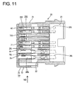
- the front mask 70 is to be mounted while the rear surface of the front plate 71 preferably is brought substantially into contact with the front surface of the terminal accommodating portion 21, the one or more guide rails 85 are slid substantially along the one or more respective guide grooves 86, and/or the one or more engaging portions 87 are slid substantially along the one or more respective slidable grooves 88, and held first after the engaging portions 87 move over the partial locking projections 89 to be engaged with them (see FIGS. 11 and 12).
- This position preferably is a testing position TP of the front mask 70.
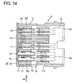
- the engaging portions 87 move over the full locking projections 90 to be engaged with them (see FIGS. 14 and 15).
- This position preferably is a proper position PP of the front mask 70.
- each larger female terminal 26L is at least partly exposed in the jig insertion opening 78 or the communicating opening 84 to double as the testing opening.
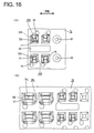
- the respective terminal insertion openings 75 of the front plate 71 are substantially aligned with the front openings of the corresponding cavities 24 as shown in FIGS. 15 and 16, so that the tabs 14 of the mating male terminals 13 are at least partly insertable into the cavities 24 through the terminal insertion openings 75 as described later.
- deformation spaces for the locking portions 25 make openings in the front surface of the terminal accommodating portion 21 upon molding the female housing 20
- the front sides of the deformation spaces for the locking portions 25 are at least partly closed by the front plate 72 when the front mask 70 substantially reaches the proper position PP.
- the side plate 72 of the front mask 70 preferably serves as an operable portion when the front mask 70 is pushed or moved from the testing position TP to the proper position PP.
- the side plate 72 comes substantially into contact with the lateral (left) surface of the terminal accommodating portion 21 as shown in FIG. 14.
- An escaping window 72A for exposing the retainer insertion opening 32 to the outside is formed at a rear end side of the side plate 72.
- the ceiling plate 73 and the bottom plate 74 are formed with one or more guide grooves 91 into which the one or more guide ribs 16 provided on the receptacle 12 of the male housing 10 are at least partly insertable, wherein the guide grooves 91 preferably extend from (or from close to) the front ends of the ceiling plate 73 and the bottom plate 74.
- the guide ribs 16 cannot be inserted into the guide grooves 91 until the front mask 70 is mounted at the proper position PP.
- the front plate 17 is also formed with the one or more rib insertion grooves 93 having the substantially same arrangement as the erroneous-connection preventing ribs 17 of the male housing 10.
- the erroneous-connection preventing ribs 17 cannot be inserted into these rib insertion grooves 93 and the rib insertion grooves 93 cannot be aligned with receiving grooves 94 perforated in the front surface of the terminal accommodating portion 21 until the front mask 70 is mounted substantially at the proper position PP.
- the two upper and lower rib insertion grooves 93 at the left side are formed with the communicating openings 84 to serve as the testing openings as described above.
- the front mask 70 preferably is to be mounted at a position immediately before the housing seal 69 to retain the housing seal 69.
- the one-piece rubber plug 35 (as the preferred resilient plug) is mounted at least partly into the mounting recess 22 formed in the rear surface of the female housing 20, and the rear holder 40 is mounted by fitting the base portion 41 behind the one-piece rubber plug 35 into the mounting recess 22.
- the base portion 41 substantially comes to lightly touch the rear surface of the one-piece rubber plug 35
- the pushing of the rear holder 40 is stopped and the locking frame(s) 50 is/are resiliently engaged with the locking projection(s) 51, whereby the rear holder 40 is so mounted as not to be detached.
- the housing seal 69 is mounted at or on the stepped portion 21A on the outer circumferential surface of the terminal accommodating portion 21 from front. Subsequently, as shown in FIG.
- the front mask 70 is mounted in the mounting direction MD to at least partly cover the front surface of the terminal accommodating portion 21 by being slid along the guide grooves 86, whereby the engaging portions 87 are engaged with the partial locking projections 89 to hold the front mask 70 at or close to the testing position TP. Further, the retainer 33 is inserted into the retainer insertion opening 32 to be held at the partial locking position (first position) where the insertion of the female terminals 26 is permitted.
- the one or more female terminals 26 secured to the ends of the wires 30 are at least partly inserted through the respective insertion paths 43 of the rear holder 40, passed through the respective wire insertion holes 36 of the one-piece rubber plug 35 preferably while resiliently widening the wire insertion holes 36, and at least partly inserted into the corresponding cavities 24.
- the one-piece rubber plug 35 is not compressed in thickness direction TD yet and the wire insertion holes 36 are not narrowed yet.
- the female terminals 26 can be inserted with a relatively small resistance.
- the female terminals 26 are partly locked by the locking portions 25 when being inserted until coming substantially into contact with the front plate 71 of the front mask 70, and are (preferably doubly) locked by successively pushing the retainer 33 to the full locking position.
- the female housing 20 preferably is set in an electrical connection testing apparatus, the probes 80 are at least partly inserted into the terminal insertion openings 75S doubling as the testing openings and the exclusively used testing openings 82, both openings 75S and 82 being formed in the front mask 70, for the smaller female terminals 26S and into the jig insertion openings 78 doubling as the testing openings and the communicating openings 84 for the larger female terminals 26L as shown in FIG. 17.
- parts of the front plates 29 of the connecting portions 28S of the smaller female terminals 26S at least partly accommodated in the cavities 24S located behind with respect to the mounting direction MD of the front mask 70 are at least partly exposed in the smaller terminal insertion openings 75S at the first and third stages as the testing openings
- the front plates 29 of the connecting portions 28S of the smaller female terminals 26S at least partly accommodated in the frontmost cavities 24S with respect to the mounting direction MD are at least partly exposed in the exclusively used testing openings 82 at the first and third stages.
- the right sides of the front ends of the connecting portions 28S of the smaller female terminals 26S at least partly accommodated in the cavities 24S located behind with respect to the mounting direction MD are at least partly exposed in the smaller terminal insertion openings 75S to serve as the testing openings at the second and fourth stages, and the right sides of the front ends of the connecting portions 28S of the smaller female terminals 26S at least partly accommodated in the frontmost cavities 24S with respect to the mounting direction MD are exposed in the exclusively used testing openings 82 at the second and fourth stages.
- the bottom right corner of the front end of the connecting portion 28L of each larger female terminal 26L is at least partly exposed in the jig insertion opening 78 or the communicating opening 84 to serve as the testing opening.
- the probes 80 are or may be substantially properly inserted into the respective testing openings, particularly the testing openings 75S, 82 for the smaller female terminals 26S by being guided by the guiding surfaces 76, 83, thereby being brought into contact with the front ends of the connecting portions 28 of the female terminals 26 exposed there for the electrical connection test.
- the jig is at least partly inserted into the jig insertion opening 78 of the corresponding cavity 24 to forcibly resiliently deform the locking portion 25 to unlock and the female terminal 26 is pulled out through the wire insertion hole 36 of the one-piece rubber plug 35 and the insertion path 36 of the rear holder 40 by pulling the wire 30. Since the one-piece rubber plug 35 is not compressed and the wire insertion holes 36 are not narrowed at this time as well, the female terminal 26 can be pulled out with a relatively smaller resistance.
- the electrical connection test is conducted again after the female terminal(s) 26 is/are reinserted or its/their posture is corrected.
- the front mask 70 is pushed from the testing position TP to the proper position PP and held at the proper position by the engagement of the engaging portions 87 with the full locking projections 90.
- the respective terminal insertion openings 75 are substantially aligned with the front openings of the corresponding cavities 24, in other words, the front openings of the connecting portions 28 of the corresponding female terminals 26 are substantially aligned with the respective terminal insertion openings 75.
- the wires 30 drawn out through the rear surface of the rear holder 40 are at least partly bundled, the wire cover 65 is mounted on the rear surface of the rear holder 40, and the wires 30 are bent and guided in the wire cover 65 to be drawn out through the draw-out opening 68.
- the lever 55 preferably is fitted or mounted on the outer side of the rear holder 40 to be mounted at the initial position shown in FIG. 1.
- the female housing 20 assembled as above is fitted or mated to the mating male housing 10 as shown by arrows in FIGS. 1 and 2.
- the guide ribs 16 of the mating receptacle 12 at least partly enter the guide grooves 91 of the front mask 70, and the followers 18 at least partly enter the entrances 60A of the cam grooves 60 of the lever 55 as shown in FIG. 18.
- the lever 55 is operated (rotated in clockwise direction of FIG. 18) by holding the operable portion 56, the female housing 20 is pulled toward the male housing 10 by cam action between the cam grooves 60 and the followers 18.
- the erroneous-connecting preventing ribs 17 projecting from the back surface of the receptacle 12 are gradually inserted into the receiving grooves 94 in the front surface of the terminal accommodating portion 21 through the rib insertion grooves 93 formed in the front mask 70.
- the tabs 14 of the male terminals 13 projecting from the back surface of the receptacle 12 are properly inserted into the corresponding terminal insertion openings 75 of the front mask 70 while being guided by the guiding surfaces 76 and at least partly enter the cavities 24 located behind to be gradually inserted into the connecting portions 28 of the female terminals 26 accommodated in the cavities 24.
- the female housing 20 is connected in an upside-down posture, the one or more erroneous-connection preventing ribs 17 of the receptacle 12 do not conform to the one or more rib insertion grooves 93 of the front mask 70.
- the erroneous-connecting preventing ribs 17 come substantially into contact with the front surface of the front plate 71 of the front mask 70, thereby hindering any further rotating operation of the lever 55. This makes it detected that the connecting posture of the female housing 20 was wrong.
- a case where the female housing 20 is fitted to a male housing 10 of a wrong specification and a case where the front mask 70 is not correctly mounted at the proper position can also be detected.
- the erroneous assembling of the housings 10, 20 and the erroneous mounting of the front mask 70 can be, in some cases, detected based on whether or not the guide ribs 16 of the receptacle 12 and the guide grooves 91 of the front mask 70 can be engaged at the start of the connecting operation of the two housings 10, 20.
- the above detection utilizing the erroneous-connecting preventing ribs 17 can be said to be a guarantee in cases where no detection could be made utilizing the guide ribs 16.
- the two housings 10, 20 may be connected again after a suitable correction is made.
- the electrical connection test is conducted with the front mask 70 temporarily held at the testing position TP, wherein the probes 80 are or can be at least partly inserted into all the smaller terminal insertion openings 75S formed in the front mask 70 excluding the rearmost ones with respect to the mounting direction MD of the frame mask 70 and the exclusively used testing openings 82 for the smaller female terminals 26S; the front ends of the connecting portions 28S of the smaller female terminals 26S at least partly accommodated in the cavities 24S located behind the corresponding cavities 24S are at least partly exposed in these smaller terminal insertion openings 75S; the parts of the front ends of the connecting portions 28S of the smaller female terminals 26S at least partly accommodated in the frontmost cavities 24S are at least partly exposed in the exclusively used testing openings 82; and the electrical connections of the respective smaller female terminals 26S are tested by the contact of the at least partly inserted probes 80 with the front ends of the connecting portions 28S of the smaller female terminals 26S.
- the probes 80 are hindered from entering the connecting portions 28S and prevented from damaging the resilient contact pieces 27 and the like provided in the connecting portions 28S since being brought into contact with the parts of the front ends of the connecting portions 28S of the smaller female terminals 26S.
- the probes 80 are or can be (also) brought into contact with the corner portions of the front ends of the connecting portions 28L of the larger female terminals 26L, thereby being similarly hindered from entering the connecting portions 28L.
- the exclusively used testing openings 82 for the smaller female terminals 26S preferably are distinguishable from the smaller terminal insertion openings 75S by having a different front shape, wherefore the number of the smaller terminal insertion openings 75S, i.e. the number of contacts can be precisely grasped from the external appearance.
- the female housing 20 is at least partly fitted to the mating male housing 10 with the front mask 70 mounted substantially at the proper position PP. If the two housings 10, 20 correctly conform to each other, the one or more erroneous-connection preventing ribs 17 and the one or more rib insertion grooves 93 are engaged with each other and the two housings 10, 20 can be completely connected. If the two housings 10, 20 are fitted with one housing set in a wrong posture such as an upside-down posture relative to the other or those having different specifications are fitted, the erroneous-connection preventing ribs 17 and the rib insertion grooves 93 cannot be engaged and the two housings 10, 20 cannot be connected, whereby erroneous assembling can be detected.
- a front mask 70 can be held at a testing portion TP located before a proper position PP with respect to a mounting direction MD of the front mask 70.
- this testing position TP parts of the front ends of connecting portions 28S of smaller female terminals 26S at least partly accommodated in smaller cavities 24S located behind the corresponding smaller cavities 24S with respect to the mounting direction MD are at least partly exposed in smaller terminal insertion openings 75S, and these smaller terminal insertion openings 75S are used also as testing openings through which probes 80 for an electrical connection test are or can be at least partly inserted.
- the front mask 70 is also formed with exclusively used testing openings 82 where parts of the front ends of the connecting portions 28S of the smaller female terminals 26S at least partly accommodated in the frontmost smaller cavities 24S with respect to the mounting direction MD are exposed when the front mask 70 is temporarily held at the testing position TP.
- the smaller terminal insertion openings 75S doubling as the testing openings are square, whereas the exclusively used testing openings 82 preferably are substantially round.
Landscapes
- Connector Housings Or Holding Contact Members (AREA)
- Details Of Connecting Devices For Male And Female Coupling (AREA)
- Testing Of Short-Circuits, Discontinuities, Leakage, Or Incorrect Line Connections (AREA)
- Manufacturing Of Electrical Connectors (AREA)
Abstract
Description
- The present invention relates to a connector with an improved construction for portions where an electrical connection test is conducted and to an assembling method therefor.
- A female connector is generally constructed such that a plurality of cavities are formed side by side in a terminal accommodating portion provided in a female connector housing and female terminals including tubular connecting portions, into which tabs of mating male terminals are inserted for connection, are accommodated in the respective cavities. Particularly, in multi-contact connectors, testing probes are brought into contact with the respective female terminals to check whether or not the respective female terminals are accommodated in correct cavities. Specifically, each probe is inserted into the connecting portion of the female terminal through a terminal insertion opening formed in the front surface of the cavity to insert the tab, thereby being brought into contact with a part of a resilient contact piece provided in the connecting portion. A connector for which an electrical connection test is conducted using such probes is disclosed, for example, in
Japanese Unexamined Patent Publication No. H11-45761 - The above probes are attached to a testing jig or the like and driven to move forward and backward by operating a lever, and an insertion stroke of the probes is set. If the probes are inserted too deep for a certain reason, there is a possibility that the resilient contact pieces are excessively deformed, for example, to be permanently set in fatigue.
- The present invention was developed in view of the above problem and an object thereof is to prevent damages and the like of female terminals during an electrical connection test.
- This object is solved according to the invention by the features of the independent claims. Preferred embodiments of the invention are subject of the dependent claims.
- According to the invention, there is provided a connector in which one or more cavities are formed in a terminal accommodating portion provided in a connector housing, and one or more female terminals having connecting portions connectable with tabs of one or more mating male terminals are at least partly accommodated in the respective cavities, wherein:
- a front mask formed with one or more terminal insertion openings into which the tabs of the male terminals are at least partly insertable and which are arranged substantially corresponding to the respective cavities is provided separately from the connector housing, the front mask being mounted substantially along the front surface of the terminal accommodating portion to be located at a proper position where the respective terminal insertion openings are substantially aligned with the corresponding cavities,
- the front mask can be positioned at a testing position which is located offset from the proper position and where parts of the front ends of the connecting portions of the female terminals at least partly accommodated in the cavities located offset with respect to the corresponding cavities are at least partly exposed in the terminal insertion openings, which can be also used as testing openings through which one or more probes for an electrical connection test are at least partly insertable, and
- the front mask is also formed with an exclusively used testing opening where a part of the front end of the connecting portion of the female terminal accommodated in the frontmost cavity with respect to the mounting direction is at least partly exposed when the front mask is located at the testing position.
- The electrical connection test can be carried out with the front mask temporarily positioned substantially at the testing position, wherein the one or more probes can be at least partly inserted into the terminal insertion openings excluding the rearmost one with respect to the mounting direction of the front mask and the exclusively used testing opening. The front ends of the connecting portions of the female terminals at least partly accommodated in the cavities located behind the corresponding cavities are at least partly exposed in the terminal insertion openings doubling as the testing openings, and the front end of the connecting portion of the female terminal at least partly accommodated in the frontmost cavity is at least partly exposed in the exclusively used testing opening. The respective inserted probes can come into contact with the front ends of the connecting portions of the female terminals to carry out the electrical connection test for the respective female terminals. When the front mask is positioned substantially to the proper position, the respective terminal insertion openings are substantially aligned with the corresponding cavities.
- Since the probes are bringable into contact with the parts of the front ends of the connecting portions of the female terminals, the entrance of the probes into the connecting portions is substantially hindered, thereby preventing damages of resilient contact pieces and the like provided in the connecting portions.
- According to a preferred embodiment of the invention, front mask forms at least part of the front walls of the cavities.
- Preferably, the front mask is to be mounted in an arranging direction of the cavities.
- Most preferably, the testing position which is located before the proper position with respect to the mounting direction.
- According to a further preferred embodiment of the invention, there is provided a connector in which a plurality of cavities are formed side by side in a terminal accommodating portion provided in a connector housing, and female terminals having tubular connecting portions through which tabs of mating male terminals are insertable for connection are accommodated in the respective cavities, wherein:
- a front mask forming the front walls of the cavities and formed with terminal insertion openings into which the tabs of the male terminals are inserted and which are arranged in an array corresponding to the respective cavities is provided separately from the connector housing, the front mask being mounted in an arranging direction of the cavities along the front surface of the terminal accommodating portion to be located at a proper position where the respective terminal insertion openings are aligned with the corresponding cavities,
- the front mask can be temporarily held at a testing position which is located before the proper position with respect to the mounting direction and where parts of the front ends of the connecting portions of the female terminals accommodated in the cavities located behind the corresponding cavities with respect to the mounting direction are exposed in the terminal insertion openings, which can be also used as testing openings through which probes for an electrical connection test are insertable, and
- the front mask is also formed with an exclusively used testing opening where a part of the front end of the connecting portion of the female terminal accommodated in the frontmost cavity with respect to the mounting direction is exposed when the front mask is temporarily held at the testing position.
- The electrical connection test is carried out with the front mask temporarily held at the testing position, wherein the probes are inserted into the terminal insertion openings excluding the rearmost one with respect to the mounting direction of the front mask and the exclusively used testing opening. The front ends of the connecting portions of the female terminals accommodated in the cavities located behind the corresponding cavities are exposed in the terminal insertion openings doubling as the testing openings, and the front end of the connecting portion of the female terminal accommodated in the frontmost cavity is exposed in the exclusively used testing opening. The respective inserted probes come into contact with the front ends of the connecting portions of the female terminals to carry out the electrical connection test for the respective female terminals. When the front mask is mounted to the proper position, the respective terminal insertion openings are aligned with the corresponding cavities.
- Since the probes are brought into contact with the parts of the front ends of the connecting portions of the female terminals, the entrance of the probes into the connecting portions is hindered, thereby preventing damages of resilient contact pieces and the like provided in the connecting portions.
- Preferably, the terminal insertion openings and the exclusively used testing opening have different front shapes.
- The exclusively used testing opening is distinguished from the terminal insertion opening by having a different front shape. Accordingly, the number of the terminal insertion openings, i.e. the number of contacts can be precisely grasped from the external appearance.
- Further preferably, one or more slanted guiding surfaces are formed over at least part of, preferably over the substantially entire circumference at the opening edges of the terminal insertion openings.
- For example, in the case where the terminal insertion openings are directly formed in the front wall of the terminal accommodating portion, holes left by leaving a mold for forming locking portions need to be so formed as to communicate with the terminal insertion openings. Thus, the slanted guiding surfaces cannot be formed over the substantially entire circumference at the terminal insertion openings. In this respect, the front mask as a separate part is provided and the terminal insertion openings are formed therein according to the present invention. Thus, it is not necessary to form the front mask with holes left by leaving a mold for forming locking portions. It is sufficient to form jig insertion openings, through which a jig for unlocking the locking portion is inserted, at a distance from the terminal insertion openings. Accordingly, the slanted guiding surfaces can be formed over at least part of, preferably over the substantially entire circumference at the opening edges of the terminal insertion openings, wherefore the tabs of the mating male terminals can be even more precisely and/or smoothly connected with the corresponding female terminals while being guided.
- Still further preferably, the front mask is provided with at least one erroneous-assembling preventing portion engageable with a mating erroneous-assembling preventing portion provided on a connecting surface of a mating connector housing when the front mask is mounted substantially at the proper position.
- The connector housing is at least partly fitted to the mating connector housing with the front mask mounted at the proper position, and are completely connected by the engagement of the erroneous-assembling preventing portions if the two connector housings correctly conform to each other. If the two connector housings are fitted with one connector housing held upside down relative to the other or the two connector housings having different specifications are fitted, the erroneous-assembling preventing portions cannot be engaged with each other and the two connector housings cannot be connected, wherefore erroneous assembling can be detected.
- Even if the two connector housings correctly conform to each other, the erroneous-assembling preventing portions cannot be similarly engaged with each other when the front mask is not mounted at the proper position. Therefore, the mounted state of the front mask can also be detected.
- Further preferably, a resilient plug is to be mounted at a rear surface of the connector housing and is to be retained by a rear holder.
- Most preferably, a movable member is provided in or on the connector housing to perform or assist a connection of the connector housing with the mating connector housing by displaying a cam action when being operated.
- According to the invention, there is further provided a method of assembling a connector, in particular according to the invention or a preferred embodiment thereof, comprising the following steps:
- providing a connector housing in which one or more cavities are formed in a terminal accommodating portion,
- at least partly accommodating one or more female terminals having connecting portions connectable with tabs of one or more mating male terminals in the respective cavities,
- providing a front mask separately from the connector housing, the front mask being formed with one or more terminal insertion openings into which the tabs of the male terminals are at least partly insertable and which are arranged substantially corresponding to the respective cavities,
- mounting the front mask substantially along the front surface of the terminal accommodating portion to be located at a proper position where the respective terminal insertion openings are substantially aligned with the corresponding cavities, and
- selectively positioning the front mask at a testing position for electrical testing purposes, wherein the testing position is located offset from the proper position and where parts of the front ends of the connecting portions of the female terminals at least partly accommodated in the cavities located offset with respect to the corresponding cavities are at least partly exposed in the terminal insertion openings, which can be also used as testing openings through which one or more probes for an electrical connection test are at least partly insertable,
- These and other objects, features and advantages of the present invention will become more apparent upon reading of the following detailed description of preferred embodiments and accompanying drawings. It should be understood that even though embodiments are separately described, single features thereof may be combined to additional embodiments.
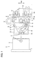
- FIG. 1 is a bottom view showing a state before two housings according to one embodiment of the invention are connected,
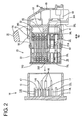
- FIG. 2 is a section of the housings when viewed from below,
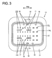
- FIG. 3 is a front view of the male housing,
- FIG. 4 is a side view of the female housing,
- FIG. 5 is a section showing an operation of mounting a front mask and a retainer,
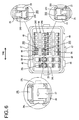
- FIG. 6 is a front view of the female housing,
- FIG. 7 is a front view of a rear holder,
- FIG. 8 is a front view of the front mask,
- FIG. 9 is a section along IX-IX of FIG. 8,
- FIG. 10 is a side view in section showing a state where the front mask is mounted at a testing position,
- FIG. 11 is a section showing the state of FIG. 10 when viewed from below,
- FIG. 12 is a front view showing the state of FIG. 10,
- FIG. 13(A) is a partial front view showing portions designed for the electrical connection test of smaller female terminals, and FIG. 13(B) is a partial front view showing portions designed for the electrical connection test of larger female terminals,
- FIG. 14 is a section showing a state where the front mask is mounted at a proper position when viewed from below,
- FIG. 15 is a front view showing the state of FIG. 14,
- FIG. 16(A) is a partial front view showing an accommodated state of the smaller female terminals, and FIG. 16(B) is a partial front view showing an accommodated state of the larger female terminals,
- FIG. 17 is a section showing a state of the electrical connection test,
- FIG. 18 is a bottom view showing a connection initial state of the two housings, and
- FIG. 19 is a section showing a locked state of a lever when viewed from below.
- Hereinafter, one preferred embodiment of the present invention is described with reference to FIGS. 1 to 19.
- In this embodiment is shown a lever-type watertight connector, which is provided with at least one male connector housing 10 (hereinafter, "
male housing 10") and at least one female connector housing 20 (hereinafter,female housing 20") connectable with each other as shown in FIGS. 1 and 2. It should be noted that sides of therespective housings - Since the connector of the present application preferably is of the hybrid type in which terminal fittings of different sizes are at least partly accommodated in the same connector housing, not only the terminal fittings, but also portions relating these terminal fittings have different (e.g. two smaller and larger) sizes and/or shapes. In the following description, the same reference numbers are given when description is common to larger and smaller parts and portions, whereas suffixes "L" or "S" are added to the reference numerals when the larger and smaller parts and portions are distinguished.
- The mating
male housing 10 preferably is to be directly connected with a device, and areceptacle 12 preferably substantially in the form of a rectangular tube projects from a wall surface of adevice casing 11 made of, e.g. a synthetic resin as also shown in FIG. 3. One or more tabs 14 of one or more, preferably a plurality of male terminals 13 at one side project substantially in array or matrix from the back surface of thereceptacle 12. More specifically, thetabs 14L of themale terminals 13L having a larger size (hereinafter, "largermale terminals 13L") are arranged in one or more rows at one or more stages (e.g. in two rows at four stages) in an area close to the lateral (right) side of the back surface of thereceptacle 12 when viewed from front, and the one ormore tabs 14S of themale terminals 13S having a smaller size (hereinafter, "smallermale terminals 13S") are arranged one or more rows at one or more stages (e.g. in in six rows at four stages) in an area stretching from an intermediate part (preferably substantially a middle part) to the vicinity of the substantially opposite lateral (left) side. The respective tabs 14 preferably project up to a position of more than about half the depth, more preferably of a substantially 2/3 depth from the opening edge of thereceptacle 12. - One or more (e.g. three)
guide ribs 16 are formed to extend substantially along (preferably each of) the ceiling and/or bottom surface(s) from the back surface of thereceptacle 12. Therespective guide ribs 16 project up to a position preferably of less than about half the depth, preferably of a substantially 1/3 depth in thereceptacle 12. Arrangements such as intervals of theguide ribs 16 preferably differ on the upper and lower sides. - One or more (e.g. four) erroneous-
connection preventing ribs 17 for preventing an erroneous connection with thefemale housing 20 project from the back surface of thereceptacle 12. The erroneous-connection preventing ribs 17 preferably are substantially in the form of plates having a laterally long cross section, and project slightly longer than thetabs 14S at one or more (e.g. four) corners of an area where thetabs 14S of thesmaller male terminals 13S are arranged. - On the lateral (upper and/or bottom) outer surface(s) of the
receptacle 12, one or more, preferably a pair offollowers 18 project at a widthwise intermediate position (preferably substantially at widthwise center positions) near the front end. - Next, the
female housing 20 is described. Thefemale housing 20 is made e.g. of a synthetic resin and preferably substantially in the form of a stepped block whose rear side is one size larger than the front side as shown in FIGS. 4 and 5, wherein the front side thereof is aterminal accommodating portion 21 and is substantially closely at least partly fittable into thereceptacle 12 of themale housing 10. A mountingrecess 22 having an open rear surface is formed in the rear side of thefemale housing 20. - As described in detail later, a
front mask 70 for forming at least part of a front wall is mounted or mountable on or to the front surface of theterminal accommodating portion 21. - One or more, preferably a plurality of cavities 24 for at least partly accommodating one or more
female terminals 26 are formed to penetrate theterminal accommodating portion 21 substantially in forward and backward directions. More specifically, as shown in FIG. 6, thelarger cavities 24L for at least partly accommodating thefemale terminals 26L having a larger size (hereinafter, "largerfemale terminals 26L") are so formed in one or more rows at one or more stages (e.g. in two rows at four stages) in an area close to the lateral (left) side when viewed from front as to substantially correspond to thetabs 14L of the largermale terminals 13L mounted in the aforementionedmale housing 10. Further, thesmaller cavities 24S for accommodating thefemale terminals 26S having a smaller size (hereinafter, "smallerfemale terminals 26S") are so formed in one or more rows at one or more stages (e.g. in six rows at four stages) in an area stretching from an intermediate part (preferably substantially a middle part) to the vicinity of the substantially opposite lateral (right) side as to substantially correspond to thetabs 14S of thesmaller male terminals 13S. - One or
more locking portions 25 are formed at lateral (bottom) sides of the respectivelarger cavity 24L. On the other hand, one group of thesmaller cavities 24S preferably at lower two stages are in a back-to-back arrangement to another group of the smaller cavities S preferably at upper two stages. Specifically, one ormore locking portions 25 are provided at ceiling sides of thesmaller cavities 24S at the upper stage in each group while being provided at bottom sides of thesmaller cavities 24S at the lower stage in each group. In each group, thesmaller cavities 24S at the one (upper) stage are slightly displaced laterally (to)right with respect to those at the (an-) other (lower) stage. - Any of the larger
female terminals 26L and the smallerfemale terminals 26S is provided with a connectingportion resilient contact piece 27 therein, and is to be secured to an end of a wire 30. In the smallerfemale terminals 26S, theresilient contact pieces 27 are displaced laterally (to right) in width direction when viewed from front, and one or morefront plates 29 are bent at an angle different from 0° or 180°, preferably substantially at right angles at the lateral (left) edges of the connecting portions 28 so as to at least partly cover spaces between theresilient contact pieces 27 and the lateral (left) edges. - The larger
female terminals 26L are to be at least partly inserted into thelarger cavities 24L from an inserting side, preferably substantially from behind, preferably stopped at their front end positions by thefront mask 70, and at least partly accommodated in thelarger cavities 24L by being resiliently locked by the lockingportions 25. The smallerfemale terminals 26S are at least partly inserted either in a correct posture or an upside-down posture into thesmaller cavities 24S from an inserting side, preferably substantially from behind, preferably stopped at their front end positions by thefront mask 70 and at least partly accommodated in thesmaller cavities 24S by being resiliently locked by the locking portions 25 (see FIGS. 10 and 11). - Further, as shown in FIG. 5, a (preferably side-type)
retainer 33 is mountable into theterminal accommodating portion 21 through aretainer insertion opening 32 formed in a side surface of theterminal accommodating portion 21 to be engaged with the rear edges (jaw portions) of the connecting portions 28 of the respectivefemale terminals 26, thereby (preferably doubly) retaining the female terminals 26 (see FIG. 17). - A one-piece rubber plug 35 (as a preferred resilient plug) preferably is to be mounted at a front side (back side) of the mounting
recess 22 formed in the rear surface of thefemale housing 20, and is retained by being pushed or positioned by arear holder 40. - The one-
piece rubber plug 35 is formed with one or more wire insertion holes 36 through which the wires 30 secured to thefemale terminals 26 are to be closely inserted, wherein the wire insertion holes 36 are arranged at positions substantially corresponding to the respective cavities 24. As shown in FIG. 17, one or morewire insertion holes wires - The
rear holder 40 is made e.g. of a synthetic resin, and preferably shaped to be substantially closely fittable into or to the rear side of the mountingrecess 22 and to include a base portion 41 (preferably substantially in the form of a thick plate) capable of pressing the rear surface of the one-piece rubber plug 35 and a (preferably substantially tubular)portion 42 arranged at least partly around thebase portion 41 and at least partly fittable onto anouter wall 22A of the mountingrecess 22 as also shown in FIG. 10. - One or
more insertion paths female terminals wires base portion 41 at positions substantially corresponding to the wire insertion holes 36 of the one-piece rubber plug 35 as shown in FIG. 7. - One or
more dovetail grooves 45 are formed in intermediate portions (preferably in the widthwise centers) of the lateral (upper and/or lower) inner wall surface(s) of thetubular portion 42 and therear holder 40, and one ormore guide grooves 46 are so formed at the (preferably substantially opposite) side(s) of the dovetail groove(s) 45 as to extend substantially in forward and backward directions, whereasdovetail projections 47 preferably are formed on the upper and lower surfaces of theouter wall 22A of the mountingrecess 22 of thefemale housing 20 and one ormore guide ribs 48 are formed at the (preferably substantially opposite) side(s) of the dovetail projection(s) 47. Further, as shown in FIG. 2, one or more, preferably a pair of lockingframes 50 are resiliently deformably formed to project forward from the lateral (left and/or right) surface(s) of thetubular portion 42 of therear holder 40. When thetubular portion 42 of therear holder 40 is at least partly fitted to a specified (predetermined or predeterminable) depth onto theouter wall 22A of the mountingrecess 22 of thefemale housing 20 while being guided by the engagement of the dovetail projection(s) 47 and the dovetail groove(s) 45 and/or the engagement of the guide rib(s) 48 and the guide groove(s) 46, the locking frame(s) 50 is/are or can be resiliently engaged with one ormore locking projections 51 projecting on the lateral (left and/or right) surface(s) of theouter wall 22A, whereby therear holder 40 is so mounted as not to be detached. At this locked position, the front surface of thebase portion 41 of therear holder 40 preferably is located immediately after the rear surface of the one-piece rubber plug 35, and therear holder 40 is movable forward from this locked position. - A lever 55 (as a preferred movable member) is to be mounted on or in the
rear holder 40. Thelever 55 is similarly made e.g. of a synthetic resin and preferably is gate-shaped as a whole by having anoperable portion 56 and a pair of lateral (left and right)side plates 57 extending from or from close to the opposite ends of theoperable portion 56. On the other hand,rotary shafts 53 symmetrically stand on the outer lateral (upper and lower) surfaces of thetubular portion 42 of therear holder 40, and thelever 55 is operably (rotatably or pivotably) supported by having therotary shafts 53 at least partly fitted into bearingholes 58 formed in bothside plates 57. - A
cam groove 60 having a specified (predetermined or predeterminable) curved configuration is formed in eachside plate 57 of thelever 55 such that anentrance 60A thereof makes an opening in the outer peripheral edge of theside plate 57. Thefollowers 18 provided on themale housing 10 are engageable with thecam grooves 60 thereby displaying a cam action. - The
lever 55 is first mounted at an initial position IP where theentrances 60A of thecam grooves 60 face substantially forward as shown in FIG. 1. When thefemale housing 20 is at least partly fitted to themale housing 10 in such a state, thefollowers 18 of themale housing 10 come to substantially face or correspond to theentrances 60A of thefollowers 18. When thelever 55 is successively operated (rotated or pivoted in clockwise direction of FIG. 1), thefemale housing 20 is pulled toward themale housing 10 while thefollowers 18 move substantially along thecam grooves 60 thus displaying the cam action and performing or assisting the connection of thefemale housing 20 and themale housing 10. Thelever 50 can be further operated (rotated or pivoted) even after the twohousings rear holder 40 moves further forward and thebase portion 41 thereof compresses the one-piece rubber plug 35 in thickness direction TD. In other words, the rotation stroke of thelever 55 is set to be more than a stroke required to connect the male andfemale housings female housings piece rubber plug 35. - A
wire cover 65 preferably is to be mounted on or to the rear surface of the aforementionedrear holder 40. Thewire cover 65 is in the form of a cap having opening front and lateral (right) surfaces. Although not described in detail, thewire cover 65 is mounted by resiliently engaging one or more, e.g. two lockingpieces 66 provided on one or more side surfaces, preferably on each of the substantially opposite side surfaces with one or more respective interlocking portions 67 (see FIG. 10) projecting at substantially corresponding positions on the rear surface of therear holder 40. Therespective wires rear holder 40 are bent and guided in thewire cover 65 and pulled out at an angle different from 0° or 180° to the extension direction of the respective terminal fitting 26, preferably substantially sideways (downward in FIG. 2) through a draw-outopening 68. - Further, a
housing seal 69 for providing sealing between thefemale housing 20 and the matingmale housing 10 preferably is to be mounted at a steppedportion 21A on the outer circumferential surface of theterminal accommodating portion 21. - The
front mask 70 is mounted or mountable on or to the front surface of theterminal accommodating portion 21 of thefemale housing 20. Thefront mask 70 preferably is made e.g. of a synthetic resin and is formed as a part different or separate from thefemale housing 20. - As shown in FIGS. 8 and 9, the
front mask 70 is comprised of afront plate 71 to be so arranged as to at least partly cover the front surface of theterminal accommodating portion 21, aside plate 72 projecting backward from the lateral (left) edge of thefront plate 71, a ceiling plate 73 and/or abottom plate 74 preferably substantially continuous with the upper and bottom ends of thefront plate 71 and theside plate 72 and projecting substantially backward. - The
front plate 71 is formed with one or moreterminal insertion openings 75 at positions substantially corresponding to the tabs 14 of the male terminals 13 of themale housing 10. Theseterminal insertion openings 75 can substantially communicate with the corresponding cavities 24 as described later when thefront mask 70 is mounted at a proper position PP. Accordingly, theterminal insertion openings 75L having a larger size and such a laterally long rectangular shape as to permit the at least partial insertion of thetabs 14L of the largermale terminals 13L (hereinafter, "largerterminal insertion openings 75L") are formed in one or more rows at one or more stages (e.g. in two rows at four stages) in an area close to the lateral (left) side of thefront plate 71 when viewed from front, and theterminal insertion openings 75S having a smaller size and such a squire shape as to permit the at least partial insertion of thetabs 14S of thesmaller male terminals 13S are formed in one or more rows at one or more stages (e.g. in six rows at four stages) in an area stretching from a middle part to the vicinity of the substantially opposite lateral (right) side. - The respective stages of the
terminal insertion openings 75 preferably are at substantially constant intervals. Along transverse direction TRD, particularly two largerterminal insertion openings 75L are arranged at a specified (predetermined or predeterminable) interval, six smallerterminal insertion openings 75S are arranged at substantially even intervals, and the largerterminal insertion opening 75L and the smallerterminal insertion opening 75S adjacent to each other are also arranged at a specified (predetermined or predeterminable) interval. - In each of the
terminal insertion openings - The
front plate 71 is also formed with one or morejig insertion openings 78 through which a jig for forcibly resiliently deforming the lockingportion 25 provided in each cavity 24 to unlock is to be at least partly inserted. For thelarger cavities 24L, thejig insertion openings 78 are formed at the lateral (left) ends of the bottom edges of the largerterminal insertion openings 75L. For thesmaller cavities 24S, thejig insertion openings 78 are formed at substantially opposite lateral (right) ends of the upper edges of the smallerterminal insertion openings 75S at the upper stages of two groups, one group preferably consisting of the first and second stages and the other group consisting of the third and fourth stages while being formed at the left ends of the bottom edges of the smallerterminal insertion openings 75S at the lower stages of the two groups. - By forming the
jig insertion openings 78 at a distance from theterminal insertion openings 75 in this way, the guiding surfaces 76 are formed preferably at all the four edges of the respectiveterminal insertion openings 75. - Out of the above smaller
terminal insertion openings 75S, those excluding the smallerterminal insertion openings 75S at the lateral (left) ends of the respective stages in FIG. 8 double as testing operations through which probes 80 for an electrical connection test (see FIG. 17) are or can be at least partly inserted from front. Further, at the lateral (right) side of the smallerterminal insertion openings 75S at the lateral (right) ends of the respective stages, one ormore testing openings 82 exclusively used to at least partly insert theprobes 80 are formed preferably at the substantially same intervals as rows of the smallerterminal insertion openings 75S. These exclusively usedtesting openings 82 preferably have a (preferably substantially round) shape different from the smallerterminal insertion openings 75S. One or more guiding surfaces 83 are also formed preferably over the substantially entire circumference of the opening edges of thetesting openings 82 to taper thetesting openings 82 toward the back. - The
jig insertion openings 78 formed for the largerterminal insertion openings 75L at the one lateral (right) side are or may be used as testing openings for the largerfemale terminals 26L at the other lateral (left) side. For the largerfemale terminals 26L at the other lateral (right) side, thejig insertion openings 78 formed for the most on the one lateral side (leftmost) smallerterminal insertion openings 75S (at the second and fourth stages) are used as the testing openings for the largerfemale terminals 26L (at the second and fourth stages), and one or more communicatingopenings 84 substantially continuous with the one lateral (left) ends of the upper surfaces ofrib insertion grooves 93 to be described later are used as the testing opening for the largerfemale terminals 26L (at the first and third stages). - The
front mask 70 is to be mounted on or to the front surface of theterminal accommodating portion 21 preferably laterally or from left side when viewed from front. Thus, one ormore guide rails 85 extending substantially in transverse direction TRD are formed at intermediate positions (preferably substantially at middle positions) preferably on substantially facing surfaces of the ceiling plate 73 and thebottom plate 74 of the front mask with respect to depth direction DD as shown in FIG. 9, whereas one ormore guide grooves 86 for guiding the guide rails 85 at least partly inserted therein are formed preferably along the substantially entire width in the lateral (upper and/or bottom) surfaces of theterminal accommodating portion 21 as shown in FIG. 10. - One or more
engaging portions 87 project in widthwise intermediate positions (preferably substantially in the widthwise centers) of the lateral (upper and/or bottom) edges of the rear surface of thefront plate 71 as shown in FIG. 5. The rear surface of each engagingportion 87 with respect to a mounting direction MD of thefront mask 70 is an intersecting or upright lockingsurface 87A and the front surface thereof is aslanted guiding surface 87B. On the other hand, aslidable groove 88 substantially along which the corresponding engagingportion 87 is slidable is formed at (preferably each) of the lateral (upper and/or bottom) edge(s) of the front surface of theterminal accommodating portion 21 preferably substantially from the lateral (left) end to a widthwise middle position, and a partial locking projection 89 (first projection) and a full locking projection 90 (second projection) are formed at or near the back side of eachslidable groove 88, thepartial locking projection 89 being located before thefull locking projection 90, while being spaced apart by a specified (predetermined or predeterminable) distance as shown in FIG. 6. - Accordingly, the
front mask 70 is to be mounted while the rear surface of thefront plate 71 preferably is brought substantially into contact with the front surface of theterminal accommodating portion 21, the one ormore guide rails 85 are slid substantially along the one or morerespective guide grooves 86, and/or the one or moreengaging portions 87 are slid substantially along the one or more respectiveslidable grooves 88, and held first after the engagingportions 87 move over thepartial locking projections 89 to be engaged with them (see FIGS. 11 and 12). This position preferably is a testing position TP of thefront mask 70. When thefront mask 70 is further pushed, the engagingportions 87 move over thefull locking projections 90 to be engaged with them (see FIGS. 14 and 15). This position preferably is a proper position PP of thefront mask 70. - When the
front mask 70 is at the testing position TP, a part of the front end of the connectingportion 28S of the smallerfemale terminal 26S at least partly accommodated in thecavity 24S located behind thecorresponding cavity 24S with respect to the mounting direction MD of thefront mask 70 is at least partly exposed in each smallerterminal insertion opening 75S doubling as the testing opening as shown in FIGS. 12 and 13. Further, a part of the front end of the connectingportion 28S of the smallerfemale terminal 26S at least partly accommodated in thefrontmost cavity 24S with respect to the mounting direction MD is exposed in each exclusively usedtesting opening 82. - The bottom right corner of the front end of the connecting
portion 28L of each largerfemale terminal 26L is at least partly exposed in thejig insertion opening 78 or the communicatingopening 84 to double as the testing opening. - When the
front mask 70 is substantially at the proper position PP, the respectiveterminal insertion openings 75 of thefront plate 71 are substantially aligned with the front openings of the corresponding cavities 24 as shown in FIGS. 15 and 16, so that the tabs 14 of the mating male terminals 13 are at least partly insertable into the cavities 24 through theterminal insertion openings 75 as described later. - Although deformation spaces for the locking
portions 25 make openings in the front surface of theterminal accommodating portion 21 upon molding thefemale housing 20, the front sides of the deformation spaces for the lockingportions 25 are at least partly closed by thefront plate 72 when thefront mask 70 substantially reaches the proper position PP. Thus, a situation where external matters may at least partly enter the deformation spaces to inadvertently resiliently deform the lockingportions 25 can be avoided. - The
side plate 72 of thefront mask 70 preferably serves as an operable portion when thefront mask 70 is pushed or moved from the testing position TP to the proper position PP. When thefront mask 70 is pushed to the proper position PP, theside plate 72 comes substantially into contact with the lateral (left) surface of theterminal accommodating portion 21 as shown in FIG. 14. An escapingwindow 72A for exposing theretainer insertion opening 32 to the outside is formed at a rear end side of theside plate 72. - Further, the ceiling plate 73 and the
bottom plate 74 are formed with one ormore guide grooves 91 into which the one ormore guide ribs 16 provided on thereceptacle 12 of themale housing 10 are at least partly insertable, wherein theguide grooves 91 preferably extend from (or from close to) the front ends of the ceiling plate 73 and thebottom plate 74. Theguide ribs 16 cannot be inserted into theguide grooves 91 until thefront mask 70 is mounted at the proper position PP. - The
front plate 17 is also formed with the one or morerib insertion grooves 93 having the substantially same arrangement as the erroneous-connection preventing ribs 17 of themale housing 10. The erroneous-connection preventing ribs 17 cannot be inserted into theserib insertion grooves 93 and therib insertion grooves 93 cannot be aligned with receivinggrooves 94 perforated in the front surface of theterminal accommodating portion 21 until thefront mask 70 is mounted substantially at the proper position PP. The two upper and lowerrib insertion grooves 93 at the left side are formed with the communicatingopenings 84 to serve as the testing openings as described above. - The
front mask 70 preferably is to be mounted at a position immediately before thehousing seal 69 to retain thehousing seal 69. - Next, functions of this embodiment are described.
- First, the one-piece rubber plug 35 (as the preferred resilient plug) is mounted at least partly into the mounting
recess 22 formed in the rear surface of thefemale housing 20, and therear holder 40 is mounted by fitting thebase portion 41 behind the one-piece rubber plug 35 into the mountingrecess 22. When thebase portion 41 substantially comes to lightly touch the rear surface of the one-piece rubber plug 35, the pushing of therear holder 40 is stopped and the locking frame(s) 50 is/are resiliently engaged with the locking projection(s) 51, whereby therear holder 40 is so mounted as not to be detached. As therear holder 40 is mounted, thehousing seal 69 is mounted at or on the steppedportion 21A on the outer circumferential surface of theterminal accommodating portion 21 from front. Subsequently, as shown in FIG. 10, thefront mask 70 is mounted in the mounting direction MD to at least partly cover the front surface of theterminal accommodating portion 21 by being slid along theguide grooves 86, whereby the engagingportions 87 are engaged with thepartial locking projections 89 to hold thefront mask 70 at or close to the testing position TP. Further, theretainer 33 is inserted into theretainer insertion opening 32 to be held at the partial locking position (first position) where the insertion of thefemale terminals 26 is permitted. - In this state, the one or more
female terminals 26 secured to the ends of the wires 30 are at least partly inserted through the respective insertion paths 43 of therear holder 40, passed through the respective wire insertion holes 36 of the one-piece rubber plug 35 preferably while resiliently widening the wire insertion holes 36, and at least partly inserted into the corresponding cavities 24. At this time, the one-piece rubber plug 35 is not compressed in thickness direction TD yet and the wire insertion holes 36 are not narrowed yet. Thus, thefemale terminals 26 can be inserted with a relatively small resistance. Thefemale terminals 26 are partly locked by the lockingportions 25 when being inserted until coming substantially into contact with thefront plate 71 of thefront mask 70, and are (preferably doubly) locked by successively pushing theretainer 33 to the full locking position. - After the
female terminals 26 are mounted as above, an electrical connection test is or may be conducted. To this end, thefemale housing 20 preferably is set in an electrical connection testing apparatus, theprobes 80 are at least partly inserted into theterminal insertion openings 75S doubling as the testing openings and the exclusively usedtesting openings 82, bothopenings front mask 70, for the smallerfemale terminals 26S and into thejig insertion openings 78 doubling as the testing openings and the communicatingopenings 84 for the largerfemale terminals 26L as shown in FIG. 17. - At this time, as shown in FIGS. 12 and 13(A), parts of the
front plates 29 of the connectingportions 28S of the smallerfemale terminals 26S at least partly accommodated in thecavities 24S located behind with respect to the mounting direction MD of thefront mask 70 are at least partly exposed in the smallerterminal insertion openings 75S at the first and third stages as the testing openings, and thefront plates 29 of the connectingportions 28S of the smallerfemale terminals 26S at least partly accommodated in thefrontmost cavities 24S with respect to the mounting direction MD are at least partly exposed in the exclusively usedtesting openings 82 at the first and third stages. Further, the right sides of the front ends of the connectingportions 28S of the smallerfemale terminals 26S at least partly accommodated in thecavities 24S located behind with respect to the mounting direction MD are at least partly exposed in the smallerterminal insertion openings 75S to serve as the testing openings at the second and fourth stages, and the right sides of the front ends of the connectingportions 28S of the smallerfemale terminals 26S at least partly accommodated in thefrontmost cavities 24S with respect to the mounting direction MD are exposed in the exclusively usedtesting openings 82 at the second and fourth stages. - Further, as shown in FIG. 13(B), the bottom right corner of the front end of the connecting
portion 28L of each largerfemale terminal 26L is at least partly exposed in thejig insertion opening 78 or the communicatingopening 84 to serve as the testing opening. - Accordingly, the
probes 80 are or may be substantially properly inserted into the respective testing openings, particularly thetesting openings female terminals 26S by being guided by the guiding surfaces 76, 83, thereby being brought into contact with the front ends of the connecting portions 28 of thefemale terminals 26 exposed there for the electrical connection test. - Here, if there is any problem such as the
female terminal 26 improperly mounted into the corresponding cavity 24, after theretainer 33 is returned to the partial locking position (first position), the jig is at least partly inserted into thejig insertion opening 78 of the corresponding cavity 24 to forcibly resiliently deform the lockingportion 25 to unlock and thefemale terminal 26 is pulled out through thewire insertion hole 36 of the one-piece rubber plug 35 and theinsertion path 36 of therear holder 40 by pulling the wire 30. Since the one-piece rubber plug 35 is not compressed and the wire insertion holes 36 are not narrowed at this time as well, thefemale terminal 26 can be pulled out with a relatively smaller resistance. - The electrical connection test is conducted again after the female terminal(s) 26 is/are reinserted or its/their posture is corrected.
- After the electrical connection test is completed, the
front mask 70 is pushed from the testing position TP to the proper position PP and held at the proper position by the engagement of the engagingportions 87 with thefull locking projections 90. With thefront mask 70 held at the proper position PP, the respectiveterminal insertion openings 75 are substantially aligned with the front openings of the corresponding cavities 24, in other words, the front openings of the connecting portions 28 of the correspondingfemale terminals 26 are substantially aligned with the respectiveterminal insertion openings 75. - On the other hand, the wires 30 drawn out through the rear surface of the
rear holder 40 are at least partly bundled, thewire cover 65 is mounted on the rear surface of therear holder 40, and the wires 30 are bent and guided in thewire cover 65 to be drawn out through the draw-outopening 68. Subsequently, thelever 55 preferably is fitted or mounted on the outer side of therear holder 40 to be mounted at the initial position shown in FIG. 1. - The
female housing 20 assembled as above is fitted or mated to the matingmale housing 10 as shown by arrows in FIGS. 1 and 2. When thefemale housing 20 is fitted by a specified (predetermined or predeterminable) amount, theguide ribs 16 of themating receptacle 12 at least partly enter theguide grooves 91 of thefront mask 70, and thefollowers 18 at least partly enter theentrances 60A of thecam grooves 60 of thelever 55 as shown in FIG. 18. Subsequently, when thelever 55 is operated (rotated in clockwise direction of FIG. 18) by holding theoperable portion 56, thefemale housing 20 is pulled toward themale housing 10 by cam action between thecam grooves 60 and thefollowers 18. - When the
female housing 20 starts being pulled, the erroneous-connecting preventingribs 17 projecting from the back surface of thereceptacle 12 are gradually inserted into the receivinggrooves 94 in the front surface of theterminal accommodating portion 21 through therib insertion grooves 93 formed in thefront mask 70. Substantially simultaneously, the tabs 14 of the male terminals 13 projecting from the back surface of thereceptacle 12 are properly inserted into the correspondingterminal insertion openings 75 of thefront mask 70 while being guided by the guiding surfaces 76 and at least partly enter the cavities 24 located behind to be gradually inserted into the connecting portions 28 of thefemale terminals 26 accommodated in the cavities 24. - At this time, if the
female housing 20 is connected in an upside-down posture, the one or more erroneous-connection preventing ribs 17 of thereceptacle 12 do not conform to the one or morerib insertion grooves 93 of thefront mask 70. Thus, immediately after thefemale housing 20 is pulled by rotating thelever 55, the erroneous-connecting preventingribs 17 come substantially into contact with the front surface of thefront plate 71 of thefront mask 70, thereby hindering any further rotating operation of thelever 55. This makes it detected that the connecting posture of thefemale housing 20 was wrong. Besides the above case, a case where thefemale housing 20 is fitted to amale housing 10 of a wrong specification and a case where thefront mask 70 is not correctly mounted at the proper position can also be detected. - The erroneous assembling of the
housings front mask 70 can be, in some cases, detected based on whether or not theguide ribs 16 of thereceptacle 12 and theguide grooves 91 of thefront mask 70 can be engaged at the start of the connecting operation of the twohousings ribs 17 can be said to be a guarantee in cases where no detection could be made utilizing theguide ribs 16. - If the erroneous assembling of the two
housings housings - When the
lever 55 is further operated (rotated or pivoted) to move thefollowers 18 to positions immediately before the ends of thecam grooves 60, the front surface of thefront mask 70 comes substantially into contact with the back surface of thereceptacle 12, thereby hindering any further approaching movements of the twohousings female terminals 26 and theterminals 13, 26 are electrically connected. - When the
lever 55 is further operated (rotated or pivoted), therear holder 40 is moved forward and thebase portion 41 presses the rear surface of the one-piece rubber plug 35 as shown in FIG. 19, whereby the one-piece rubber plug 35 is compressed in thickness direction TD and, as a result, the wire insertion holes 36 are narrowed to be brought substantially into close contact with the wires 30 in radially inward directions, i.e. strong sealing is given. When thelever 55 is operated (rotated or pivoted) to the ending position EP, an interlockingportion 59 at the rear edge of thelever 55 is resiliently engaged with alever locking portion 96 provided on thewire cover 65, thereby preventing the returning operation of thelever 55 and the separation of the twohousings - As described above, according to this embodiment, the electrical connection test is conducted with the
front mask 70 temporarily held at the testing position TP, wherein theprobes 80 are or can be at least partly inserted into all the smallerterminal insertion openings 75S formed in thefront mask 70 excluding the rearmost ones with respect to the mounting direction MD of theframe mask 70 and the exclusively usedtesting openings 82 for the smallerfemale terminals 26S; the front ends of the connectingportions 28S of the smallerfemale terminals 26S at least partly accommodated in thecavities 24S located behind the correspondingcavities 24S are at least partly exposed in these smallerterminal insertion openings 75S; the parts of the front ends of the connectingportions 28S of the smallerfemale terminals 26S at least partly accommodated in thefrontmost cavities 24S are at least partly exposed in the exclusively usedtesting openings 82; and the electrical connections of the respective smallerfemale terminals 26S are tested by the contact of the at least partly insertedprobes 80 with the front ends of the connectingportions 28S of the smallerfemale terminals 26S. In other words, theprobes 80 are hindered from entering the connectingportions 28S and prevented from damaging theresilient contact pieces 27 and the like provided in the connectingportions 28S since being brought into contact with the parts of the front ends of the connectingportions 28S of the smallerfemale terminals 26S. - The
probes 80 are or can be (also) brought into contact with the corner portions of the front ends of the connectingportions 28L of the largerfemale terminals 26L, thereby being similarly hindered from entering the connectingportions 28L. - The exclusively used
testing openings 82 for the smallerfemale terminals 26S preferably are distinguishable from the smallerterminal insertion openings 75S by having a different front shape, wherefore the number of the smallerterminal insertion openings 75S, i.e. the number of contacts can be precisely grasped from the external appearance. - The
female housing 20 is at least partly fitted to the matingmale housing 10 with thefront mask 70 mounted substantially at the proper position PP. If the twohousings connection preventing ribs 17 and the one or morerib insertion grooves 93 are engaged with each other and the twohousings housings connection preventing ribs 17 and therib insertion grooves 93 cannot be engaged and the twohousings - Even if the two
housings connection preventing ribs 17 and therib insertion grooves 93 cannot be engaged if thefront mask 70 is not mounted substantially at the proper position PP. Therefore, the mounted state of thefront mask 70 can also be detected. - Accordingly, to prevent damages and the like of female terminals during an electrical connection test, a
front mask 70 can be held at a testing portion TP located before a proper position PP with respect to a mounting direction MD of thefront mask 70. At this testing position TP, parts of the front ends of connectingportions 28S of smallerfemale terminals 26S at least partly accommodated insmaller cavities 24S located behind the correspondingsmaller cavities 24S with respect to the mounting direction MD are at least partly exposed in smallerterminal insertion openings 75S, and these smallerterminal insertion openings 75S are used also as testing openings through which probes 80 for an electrical connection test are or can be at least partly inserted. Thefront mask 70 is also formed with exclusively usedtesting openings 82 where parts of the front ends of the connectingportions 28S of the smallerfemale terminals 26S at least partly accommodated in the frontmostsmaller cavities 24S with respect to the mounting direction MD are exposed when thefront mask 70 is temporarily held at the testing position TP. The smallerterminal insertion openings 75S doubling as the testing openings are square, whereas the exclusively usedtesting openings 82 preferably are substantially round. - The present invention is not limited to the above described and illustrated embodiment. For example, the following embodiments are also embraced by the technical scope of the present invention as defined by the claims. Beside the following embodiments, various changes can be made without departing from the scope and spirit of the present invention as defined by the claims.
- (1) The shape of the exclusively used testing openings for the smaller female terminals is not limited to the round shape shown in the foregoing embodiment, and may be, for example, a triangular or hexagonal shape. In short, any shape will do provided that it is different from the front shape of the smaller terminal insertion openings.
If the exclusively used testing operations preferably have a front shape different from the smaller terminal insertion openings, it is advantageous to precisely grasp the number of contacts, but they may have the substantially same front shape. Such testing openings are embraced by the technical scope of the present invention. - (2) The present invention is not limited to connectors of the hybrid type in which terminal fittings having different sizes are accommodated in the same connector housing, and is similarly applicable to normal connectors accommodating terminal fittings having one size. For example, if only the smaller female terminals are accommodated in this embodiment, the electrical connection test by the probes can be conducted, utilizing the terminal insertion openings and the exclusively used testing openings for all the female terminals.
- (3) The electrical connection test can be conducted only utilizing the terminal insertion openings and the exclusively used testing openings, for example, by suitably setting intervals of the cavities, i.e. the terminal insertion openings formed in the front mask even if the connector is of the hybrid type.
- (4) The present invention is similarly applicable to connectors using no lever or other types of movable members such as sliders and/or non-watertight connectors.
-
- 10 ...
- male housing (mating connector housing)
- 13S ...
- smaller male terminal
- 14S ...
- tab
- 17 ...
- erroneous-connection preventing rib (erroneous-assembling preventing portion)
- 20 ...
- female housing (connector housing)
- 21 ...
- terminal accommodating portion
- 24S ...
- smaller cavity
- 26S ...
- smaller female terminal
- 28S ...
- connecting portion
- 29 ...
- front plate
- 70 ...
- front mask
- 75S ...
- smaller terminal insertion opening (testing opening)
- 76, 83...
- guiding surface (slanted surface)
- 80 ...
- probe
- 82 ...
- exclusively used testing opening
- 93 ..
- rib insertion groove (erroneous-assembling preventing portion)
Claims (10)
- A connector in which one or more cavities (24) are formed in a terminal accommodating portion (21) provided in a connector housing (20), and one or more female terminals (26) having connecting portions (28) connectable with tabs (14) of one or more mating male terminals (13) are at least partly accommodated in the respective cavities (24), wherein:a front mask (70) formed with one or more terminal insertion openings (75) into which the tabs (14) of the male terminals (13) are at least partly insertable and which are arranged substantially corresponding to the respective cavities (24) is provided separately from the connector housing (20), the front mask (70) being mounted substantially along the front surface of the terminal accommodating portion (21) to be located at a proper position (PP) where the respective terminal insertion openings (75) are substantially aligned with the corresponding cavities (24),the front mask (70) can be positioned at a testing position (TP) which is located offset from the proper position (PP) and where parts of the front ends of the connecting portions (28) of the female terminals (26) at least partly accommodated in the cavities (24) located offset with respect to the corresponding cavities (24) are at least partly exposed in the terminal insertion openings (75), which can be also used as testing openings (75) through which one or more probes (80) for an electrical connection test are at least partly insertable, andthe front mask (70) is also formed with an exclusively used testing opening (82) where a part of the front end of the connecting portion (28) of the female terminal (26) accommodated in the frontmost cavity with respect to the mounting direction (MD) is at least partly exposed when the front mask (70) is located at the testing position (TP).
- A connector according to claim 1, wherein front mask (70) forms at least part of the front walls of the cavities (24).
- A connector according to one or more of the preceding claims, wherein the front mask (70) is to be mounted in an arranging direction of the cavities (24).
- A connector according to one or more of the preceding claims, wherein the testing position (TP) which is located before the proper position (PP) with respect to the mounting direction (MD).
- A connector according to one or more of the preceding claims, wherein the terminal insertion openings (75) and the exclusively used testing opening (82) have different front shapes.
- A connector according to one or more of the preceding claims, wherein one or more slanted guiding surfaces (76; 83) are formed over at least part of, preferably over the substantially entire circumference at the opening edges of the terminal insertion openings (75).
- A connector according to one or more of the preceding claims, wherein the front mask (70) is provided with at least one erroneous-assembling preventing portion (93) engageable with a mating erroneous-assembling preventing portion (17) provided on a connecting surface of a mating connector housing (10) when the front mask (70) is mounted substantially at the proper position (PP).
- A connector according to one or more of the preceding claims, wherein a resilient plug (35) is to be mounted at a rear surface of the connector housing (20) and is to be retained by a rear holder (40).
- A connector according to one or more of the preceding claims, wherein a movable member (55) is provided in or on the connector housing (20) to perform or assist a connection of the connector housing (20) with the mating connector housing (10) by displaying a cam action when being operated.
- A method of assembling a connector, comprising the following steps:providing a connector housing (20) in which one or more cavities (24) are formed in a terminal accommodating portion (21),at least partly accommodating one or more female terminals (26) having connecting portions (28) connectable with tabs (14) of one or more mating male terminals (13) in the respective cavities (24),providing a front mask (70) separately from the connector housing (20), the front mask (70) being formed with one or more terminal insertion openings (75) into which the tabs (14) of the male terminals (13) are at least partly insertable and which are arranged substantially corresponding to the respective cavities (24),mounting the front mask (70) substantially along the front surface of the terminal accommodating portion (21) to be located at a proper position (PP) where the respective terminal insertion openings (75) are substantially aligned with the corresponding cavities (24), andselectively positioning the front mask (70) at a testing position (TP) for electrical testing purposes, wherein the testing position (TP) is located offset from the proper position (PP) and where parts of the front ends of the connecting portions (28) of the female terminals (26) at least partly accommodated in the cavities (24) located offset with respect to the corresponding cavities (24) are at least partly exposed in the terminal insertion openings (75), which can be also used as testing openings (75) through which one or more probes (80) for an electrical connection test are at least partly insertable,wherein the front mask (70) is also formed with an exclusively used testing opening (82) where a part of the front end of the connecting portion (28) of the female terminal (26) accommodated in the frontmost cavity with respect to the mounting direction (MD) is at least partly exposed when the front mask (70) is located at the testing position (TP).
Applications Claiming Priority (1)
| Application Number | Priority Date | Filing Date | Title |
|---|---|---|---|
| JP2005186878A JP4475182B2 (en) | 2005-06-27 | 2005-06-27 | connector |
Publications (2)
| Publication Number | Publication Date |
|---|---|
| EP1753091A1 true EP1753091A1 (en) | 2007-02-14 |
| EP1753091B1 EP1753091B1 (en) | 2008-03-26 |
Family
ID=36933339
Family Applications (1)
| Application Number | Title | Priority Date | Filing Date |
|---|---|---|---|
| EP06012418A Expired - Fee Related EP1753091B1 (en) | 2005-06-27 | 2006-06-16 | A connector and a method of assembling it |
Country Status (4)
| Country | Link |
|---|---|
| US (1) | US7303437B2 (en) |
| EP (1) | EP1753091B1 (en) |
| JP (1) | JP4475182B2 (en) |
| DE (1) | DE602006000810T2 (en) |
Cited By (3)
| Publication number | Priority date | Publication date | Assignee | Title |
|---|---|---|---|---|
| EP2124298A1 (en) | 2008-04-25 | 2009-11-25 | Molex Incorporated | Connector with TPA position dectection |
| EP2251940A1 (en) | 2009-05-14 | 2010-11-17 | Molex Incorporated | Electrical connector with water draining |
| CN104112945A (en) * | 2013-04-18 | 2014-10-22 | 住友电装株式会社 | Lever-type connector |
Families Citing this family (20)
| Publication number | Priority date | Publication date | Assignee | Title |
|---|---|---|---|---|
| JP4395784B2 (en) * | 2006-03-03 | 2010-01-13 | 住友電装株式会社 | Lever type connector |
| JP5360987B2 (en) * | 2009-09-24 | 2013-12-04 | 矢崎総業株式会社 | Lever type connector |
| JP5590703B2 (en) * | 2009-10-07 | 2014-09-17 | 矢崎総業株式会社 | Connector with joint function |
| JP5582632B2 (en) * | 2009-10-13 | 2014-09-03 | 矢崎総業株式会社 | Connector with joint function |
| JP2013187126A (en) * | 2012-03-09 | 2013-09-19 | Yazaki Corp | Connector |
| JP5337271B2 (en) * | 2012-04-09 | 2013-11-06 | 三菱電機株式会社 | Connector device |
| JP2014010951A (en) * | 2012-06-28 | 2014-01-20 | Tyco Electronics Japan Kk | Electric connector |
| JP5850337B2 (en) * | 2012-09-06 | 2016-02-03 | 住友電装株式会社 | connector |
| JP2014053148A (en) * | 2012-09-06 | 2014-03-20 | Sumitomo Wiring Syst Ltd | Connector |
| JP2014211999A (en) * | 2013-04-18 | 2014-11-13 | 住友電装株式会社 | Lever type connector |
| KR101786594B1 (en) * | 2016-07-22 | 2017-10-18 | 주식회사 경신 | Connector |
| JP6441866B2 (en) * | 2016-09-21 | 2018-12-19 | 矢崎総業株式会社 | Lever type connector |
| US9960537B2 (en) * | 2016-09-28 | 2018-05-01 | Te Connectivity Corporation | Connector assembly with shipping cap |
| JP2019040687A (en) * | 2017-08-23 | 2019-03-14 | 住友電装株式会社 | Rubber stopper and waterproof connector |
| KR101830415B1 (en) * | 2017-09-18 | 2018-02-20 | 주식회사 경신 | Connector |
| DE102017123405A1 (en) * | 2017-10-09 | 2019-04-11 | Te Connectivity Germany Gmbh | Contact device and contact system |
| US10601177B1 (en) * | 2018-09-07 | 2020-03-24 | Lear Corporation | Electrical connector lock with reverse stop |
| DE102018009478A1 (en) * | 2018-12-04 | 2020-06-04 | Kostal Kontakt Systeme Gmbh | Connector arrangement |
| JP7574808B2 (en) * | 2022-01-18 | 2024-10-29 | 住友電装株式会社 | connector |
| CN114944566A (en) * | 2022-06-27 | 2022-08-26 | 华泽通精密科技(东莞)有限公司 | Magnetic attraction inclined-angle connector |
Citations (2)
| Publication number | Priority date | Publication date | Assignee | Title |
|---|---|---|---|---|
| EP1137118A2 (en) * | 2000-03-14 | 2001-09-26 | Yazaki Corporation | A connector having at least one contact-pin inserting port for insertion of a conduction contact pin of a connector conduction-test tool |
| US20020086580A1 (en) * | 2000-12-28 | 2002-07-04 | Sumitomo Wiring Systems, Ltd. | Connector and continuity test method for connector |
Family Cites Families (9)
| Publication number | Priority date | Publication date | Assignee | Title |
|---|---|---|---|---|
| JPH07130441A (en) * | 1993-11-04 | 1995-05-19 | Sumitomo Wiring Syst Ltd | Connector inspection device |
| JP2578430Y2 (en) * | 1993-11-25 | 1998-08-13 | 住友電装株式会社 | Mounting structure of retainer in connector |
| JP3043568B2 (en) * | 1994-03-14 | 2000-05-22 | 住友電装株式会社 | connector |
| JP2725672B2 (en) * | 1997-03-14 | 1998-03-11 | 住友電装株式会社 | connector |
| JP3211735B2 (en) * | 1997-07-29 | 2001-09-25 | 住友電装株式会社 | Female connector |
| JPH11238541A (en) * | 1998-02-20 | 1999-08-31 | Yazaki Corp | connector |
| JP3534239B2 (en) * | 1999-10-05 | 2004-06-07 | 住友電装株式会社 | connector |
| DE10017868B4 (en) * | 2000-04-11 | 2004-03-04 | Leopold Kostal Gmbh & Co. Kg | Electrical connector part |
| JP2004037164A (en) * | 2002-07-01 | 2004-02-05 | Sumitomo Wiring Syst Ltd | Connector inspection device |
-
2005
- 2005-06-27 JP JP2005186878A patent/JP4475182B2/en not_active Expired - Fee Related
-
2006
- 2006-06-16 DE DE602006000810T patent/DE602006000810T2/en not_active Expired - Lifetime
- 2006-06-16 EP EP06012418A patent/EP1753091B1/en not_active Expired - Fee Related
- 2006-06-26 US US11/474,620 patent/US7303437B2/en not_active Expired - Fee Related
Patent Citations (2)
| Publication number | Priority date | Publication date | Assignee | Title |
|---|---|---|---|---|
| EP1137118A2 (en) * | 2000-03-14 | 2001-09-26 | Yazaki Corporation | A connector having at least one contact-pin inserting port for insertion of a conduction contact pin of a connector conduction-test tool |
| US20020086580A1 (en) * | 2000-12-28 | 2002-07-04 | Sumitomo Wiring Systems, Ltd. | Connector and continuity test method for connector |
Cited By (4)
| Publication number | Priority date | Publication date | Assignee | Title |
|---|---|---|---|---|
| EP2124298A1 (en) | 2008-04-25 | 2009-11-25 | Molex Incorporated | Connector with TPA position dectection |
| EP2251940A1 (en) | 2009-05-14 | 2010-11-17 | Molex Incorporated | Electrical connector with water draining |
| CN104112945A (en) * | 2013-04-18 | 2014-10-22 | 住友电装株式会社 | Lever-type connector |
| CN104112945B (en) * | 2013-04-18 | 2017-04-12 | 住友电装株式会社 | Lever-type connector |
Also Published As
| Publication number | Publication date |
|---|---|
| JP4475182B2 (en) | 2010-06-09 |
| DE602006000810T2 (en) | 2009-04-16 |
| US7303437B2 (en) | 2007-12-04 |
| EP1753091B1 (en) | 2008-03-26 |
| US20060292907A1 (en) | 2006-12-28 |
| JP2007005239A (en) | 2007-01-11 |
| DE602006000810D1 (en) | 2008-05-08 |
Similar Documents
| Publication | Publication Date | Title |
|---|---|---|
| EP1753091B1 (en) | A connector and a method of assembling it | |
| EP1990869B1 (en) | A connector and assembling method thereof | |
| US6276964B1 (en) | Joint connector | |
| EP1715551B1 (en) | A connector and a method of assembling it | |
| JP4103333B2 (en) | Connector and continuity inspection method in connector | |
| US7588446B2 (en) | Connector and a connector assembly | |
| EP2495821A1 (en) | Connector and assembling method therefor | |
| EP2075880A1 (en) | Lever-type connector, connector assembly and connecting method | |
| EP1689041B1 (en) | A connector, a connector testing apparatus and method | |
| US5859534A (en) | Connector examination and correction devices and methods examining and correcting same | |
| KR100740853B1 (en) | A connector and a method of assembling it | |
| EP1742302A1 (en) | A connector, connector assembly and assembling method therefor | |
| US7114999B2 (en) | Connector and a connector assembly | |
| US6132252A (en) | Electrical connector with locking of the contact terminals | |
| JP3433690B2 (en) | Joint connector | |
| JP3890955B2 (en) | Covered connector | |
| JP3433689B2 (en) | Joint connector | |
| JP7417204B2 (en) | connector | |
| JP2007026758A (en) | Waterproof connector | |
| JP2000137052A (en) | Connector inspection device | |
| JP2001091563A (en) | Connector continuity inspection tool |
Legal Events
| Date | Code | Title | Description |
|---|---|---|---|
| PUAI | Public reference made under article 153(3) epc to a published international application that has entered the european phase |
Free format text: ORIGINAL CODE: 0009012 |
|
| 17P | Request for examination filed |
Effective date: 20060629 |
|
| AK | Designated contracting states |
Kind code of ref document: A1 Designated state(s): AT BE BG CH CY CZ DE DK EE ES FI FR GB GR HU IE IS IT LI LT LU LV MC NL PL PT RO SE SI SK TR |
|
| AX | Request for extension of the european patent |
Extension state: AL BA HR MK YU |
|
| GRAP | Despatch of communication of intention to grant a patent |
Free format text: ORIGINAL CODE: EPIDOSNIGR1 |
|
| AKX | Designation fees paid |
Designated state(s): DE FR |
|
| GRAS | Grant fee paid |
Free format text: ORIGINAL CODE: EPIDOSNIGR3 |
|
| GRAA | (expected) grant |
Free format text: ORIGINAL CODE: 0009210 |
|
| AK | Designated contracting states |
Kind code of ref document: B1 Designated state(s): DE FR |
|
| REF | Corresponds to: |
Ref document number: 602006000810 Country of ref document: DE Date of ref document: 20080508 Kind code of ref document: P |
|
| ET | Fr: translation filed | ||
| PLBE | No opposition filed within time limit |
Free format text: ORIGINAL CODE: 0009261 |
|
| STAA | Information on the status of an ep patent application or granted ep patent |
Free format text: STATUS: NO OPPOSITION FILED WITHIN TIME LIMIT |
|
| 26N | No opposition filed |
Effective date: 20081230 |
|
| PGFP | Annual fee paid to national office [announced via postgrant information from national office to epo] |
Ref country code: DE Payment date: 20130612 Year of fee payment: 8 |
|
| PGFP | Annual fee paid to national office [announced via postgrant information from national office to epo] |
Ref country code: FR Payment date: 20130624 Year of fee payment: 8 |
|
| REG | Reference to a national code |
Ref country code: DE Ref legal event code: R119 Ref document number: 602006000810 Country of ref document: DE |
|
| REG | Reference to a national code |
Ref country code: DE Ref legal event code: R119 Ref document number: 602006000810 Country of ref document: DE Effective date: 20150101 |
|
| REG | Reference to a national code |
Ref country code: FR Ref legal event code: ST Effective date: 20150227 |
|
| PG25 | Lapsed in a contracting state [announced via postgrant information from national office to epo] |
Ref country code: DE Free format text: LAPSE BECAUSE OF NON-PAYMENT OF DUE FEES Effective date: 20150101 |
|
| PG25 | Lapsed in a contracting state [announced via postgrant information from national office to epo] |
Ref country code: FR Free format text: LAPSE BECAUSE OF NON-PAYMENT OF DUE FEES Effective date: 20140630 |