EP1752860B1 - Terminal mobile avec écran tactile à rétroaction haptique et procédé correspondant - Google Patents
Terminal mobile avec écran tactile à rétroaction haptique et procédé correspondant Download PDFInfo
- Publication number
- EP1752860B1 EP1752860B1 EP06016840.8A EP06016840A EP1752860B1 EP 1752860 B1 EP1752860 B1 EP 1752860B1 EP 06016840 A EP06016840 A EP 06016840A EP 1752860 B1 EP1752860 B1 EP 1752860B1
- Authority
- EP
- European Patent Office
- Prior art keywords
- vibrator
- touch screen
- display part
- terminal
- square wave
- Prior art date
- Legal status (The legal status is an assumption and is not a legal conclusion. Google has not performed a legal analysis and makes no representation as to the accuracy of the status listed.)
- Expired - Fee Related
Links
- 238000000034 method Methods 0.000 title claims description 5
- 230000035807 sensation Effects 0.000 description 26
- 238000002474 experimental method Methods 0.000 description 11
- 238000010295 mobile communication Methods 0.000 description 11
- 238000010276 construction Methods 0.000 description 10
- 238000010586 diagram Methods 0.000 description 6
- 230000006870 function Effects 0.000 description 4
- 238000012545 processing Methods 0.000 description 4
- 238000004891 communication Methods 0.000 description 2
- 239000000463 material Substances 0.000 description 2
- 230000004044 response Effects 0.000 description 2
- 230000000007 visual effect Effects 0.000 description 2
- 241001422033 Thestylus Species 0.000 description 1
- 230000015572 biosynthetic process Effects 0.000 description 1
- 238000012790 confirmation Methods 0.000 description 1
- 230000007423 decrease Effects 0.000 description 1
- 230000001419 dependent effect Effects 0.000 description 1
- 238000011161 development Methods 0.000 description 1
- 230000000694 effects Effects 0.000 description 1
- 238000005516 engineering process Methods 0.000 description 1
- 239000011521 glass Substances 0.000 description 1
- 230000001771 impaired effect Effects 0.000 description 1
- 229920003023 plastic Polymers 0.000 description 1
- 239000004417 polycarbonate Substances 0.000 description 1
- 229920000515 polycarbonate Polymers 0.000 description 1
- 230000000644 propagated effect Effects 0.000 description 1
- 229910052710 silicon Inorganic materials 0.000 description 1
- 239000010703 silicon Substances 0.000 description 1
- 239000012780 transparent material Substances 0.000 description 1
Images


Classifications
-
- G—PHYSICS
- G06—COMPUTING; CALCULATING OR COUNTING
- G06F—ELECTRIC DIGITAL DATA PROCESSING
- G06F3/00—Input arrangements for transferring data to be processed into a form capable of being handled by the computer; Output arrangements for transferring data from processing unit to output unit, e.g. interface arrangements
- G06F3/01—Input arrangements or combined input and output arrangements for interaction between user and computer
- G06F3/016—Input arrangements with force or tactile feedback as computer generated output to the user
-
- G—PHYSICS
- G06—COMPUTING; CALCULATING OR COUNTING
- G06F—ELECTRIC DIGITAL DATA PROCESSING
- G06F3/00—Input arrangements for transferring data to be processed into a form capable of being handled by the computer; Output arrangements for transferring data from processing unit to output unit, e.g. interface arrangements
- G06F3/01—Input arrangements or combined input and output arrangements for interaction between user and computer
- G06F3/048—Interaction techniques based on graphical user interfaces [GUI]
- G06F3/0487—Interaction techniques based on graphical user interfaces [GUI] using specific features provided by the input device, e.g. functions controlled by the rotation of a mouse with dual sensing arrangements, or of the nature of the input device, e.g. tap gestures based on pressure sensed by a digitiser
- G06F3/0488—Interaction techniques based on graphical user interfaces [GUI] using specific features provided by the input device, e.g. functions controlled by the rotation of a mouse with dual sensing arrangements, or of the nature of the input device, e.g. tap gestures based on pressure sensed by a digitiser using a touch-screen or digitiser, e.g. input of commands through traced gestures
- G06F3/04886—Interaction techniques based on graphical user interfaces [GUI] using specific features provided by the input device, e.g. functions controlled by the rotation of a mouse with dual sensing arrangements, or of the nature of the input device, e.g. tap gestures based on pressure sensed by a digitiser using a touch-screen or digitiser, e.g. input of commands through traced gestures by partitioning the display area of the touch-screen or the surface of the digitising tablet into independently controllable areas, e.g. virtual keyboards or menus
-
- H—ELECTRICITY
- H04—ELECTRIC COMMUNICATION TECHNIQUE
- H04M—TELEPHONIC COMMUNICATION
- H04M1/00—Substation equipment, e.g. for use by subscribers
- H04M1/02—Constructional features of telephone sets
- H04M1/23—Construction or mounting of dials or of equivalent devices; Means for facilitating the use thereof
-
- G—PHYSICS
- G06—COMPUTING; CALCULATING OR COUNTING
- G06F—ELECTRIC DIGITAL DATA PROCESSING
- G06F2203/00—Indexing scheme relating to G06F3/00 - G06F3/048
- G06F2203/048—Indexing scheme relating to G06F3/048
- G06F2203/04809—Textured surface identifying touch areas, e.g. overlay structure for a virtual keyboard
-
- H—ELECTRICITY
- H01—ELECTRIC ELEMENTS
- H01H—ELECTRIC SWITCHES; RELAYS; SELECTORS; EMERGENCY PROTECTIVE DEVICES
- H01H2215/00—Tactile feedback
-
- H—ELECTRICITY
- H01—ELECTRIC ELEMENTS
- H01H—ELECTRIC SWITCHES; RELAYS; SELECTORS; EMERGENCY PROTECTIVE DEVICES
- H01H2215/00—Tactile feedback
- H01H2215/05—Tactile feedback electromechanical
- H01H2215/052—Tactile feedback electromechanical piezoelectric
-
- H—ELECTRICITY
- H01—ELECTRIC ELEMENTS
- H01H—ELECTRIC SWITCHES; RELAYS; SELECTORS; EMERGENCY PROTECTIVE DEVICES
- H01H2231/00—Applications
- H01H2231/022—Telephone handset
-
- H—ELECTRICITY
- H04—ELECTRIC COMMUNICATION TECHNIQUE
- H04M—TELEPHONIC COMMUNICATION
- H04M2250/00—Details of telephonic subscriber devices
- H04M2250/16—Details of telephonic subscriber devices including more than one display unit
-
- H—ELECTRICITY
- H04—ELECTRIC COMMUNICATION TECHNIQUE
- H04M—TELEPHONIC COMMUNICATION
- H04M2250/00—Details of telephonic subscriber devices
- H04M2250/22—Details of telephonic subscriber devices including a touch pad, a touch sensor or a touch detector
-
- H—ELECTRICITY
- H04—ELECTRIC COMMUNICATION TECHNIQUE
- H04M—TELEPHONIC COMMUNICATION
- H04M2250/00—Details of telephonic subscriber devices
- H04M2250/56—Details of telephonic subscriber devices including a user help function
Definitions
- the present invention relates to a terminal, and more particularly, to a mobile terminal having a touch screen.
- a mobile communication terminal having a touch screen type display.
- the user pushes push-button type mechanical key buttons of a conventional non-touch-screen type mobile communication terminal, the user can feel tactile sensation in which the key buttons have been slightly pushed inward, and therefore, the user of the terminal can easily recognize that the key buttons have been correctly pushed.
- the conventional touch screen type mobile communication terminal has problems in that, when the user of the terminal pushes the key buttons on the touch screen of the terminal, the user cannot feel tactile sensation in which the key buttons have been pushed, and therefore, the user of the terminal cannot easily recognize that the key buttons have been correctly pushed.
- EP 1 517 224 A2 discloses a display device comprising a touch screen for the visual display of information and for the input of commands and an actuator for moving the touch screen in a direction essentially perpendicular to the touch screen.
- the present invention provides a touch screen assembly according to claim 1, a terminal according to claim 9, and a key input method according to claim 11.
- Preferred embodiments of the invention are given in the dependent sub-claims.
- a touch screen assembly in accordance with the present invention includes a touch screen type display part for displaying input parts used for a user to input information, a vibrator for providing vibration to the display part when an input operation is carried out through the input parts, and a vibrator driving part for driving the vibrator, wherein the vibrator driving part provides a voltage square wave to the vibrator so as to instantaneously vibrate the display part.
- a terminal in another aspect of the present invention, includes the above-described touch screen assembly according to the present invention.
- a key input method on a terminal having a touch screen includes displaying input parts on a touch screen, sensing that a user has performed an input operation through the input parts, and, when the input operation is sensed, providing instantaneous vibration to the touch screen.
- FIG. 1 is a perspective view illustrating a mobile terminal according to a first embodiment
- FIG. 2 is a sectional view taken along line I-I' of FIG. 1 ;
- FIG. 3 is a perspective view illustrating a mobile terminal according to a second embodiment
- FIG. 4 is a schematic block diagram of the mobile terminal according to the second embodiment ;
- FIG. 5 is a schematic block diagram illustrating a mobile terminal having a touch screen according to a third embodiment ;
- FIG. 6 is a front view of the mobile terminal having the touch screen according to the third embodiment ;
- FIGs . 7A and 7B are circuit diagrams schematically illustrating the construction of a vibrator of the mobile terminal according to the third embodiment ;
- FIG. 8 is a front view illustrating a preferred position of a vibrator in a mobile terminal according to Embodiment 3-1 ;
- FIGs. 9A and 9B are sectional views taken along line II-II' of FIG. 8 ;
- FIG. 10 is a front view illustrating a preferred position of a vibrator in a mobile terminal according to Embodiment 3-2 ;
- FIGs. 11A and 11B are sectional views taken along line III-III' of FIG. 10 .
- the present invention may be applied to various kinds of terminals, such as a game device, as well as mobile communication terminals, such as a personal digital assistant (PDA), a portable phone, and a smart phone.
- a game device such as a game device
- mobile communication terminals such as a personal digital assistant (PDA), a portable phone, and a smart phone.
- PDA personal digital assistant
- portable phone such as a portable phone
- smart phone such as a smart phone.
- the present invention may be applied to all kinds of mobile terminals having at least one touch screen type display part.
- the mobile terminal according to the present invention includes two display parts, and at least one of the two display parts is a touch screen type display part.
- FIG. 1 is a perspective view illustrating a mobile terminal according to a first embodiment
- FIG. 2 is a sectional view taken along line I-I' of FIG. 1 .
- the mobile terminal preferably includes a first touch screen type display unit 100, a touch screen protection film part 150 formed at the front of the first display part 100, and a second display part 400, which is exclusively used as a display.
- the mobile terminal includes other components, such as a control part and a memory part, in addition to the above-mentioned components.
- the other components of the mobile terminal are not directly related to the present invention, and therefore, a description of the other components of the mobile terminal will not be given below for simplicity and clarity of description.
- the first display part 100 is a touch screen that displays key buttons used to manipulate the mobile terminal.
- the second display part 400 displays information of the mobile terminal or motion pictures.
- the second display part 400 may be constructed with a touch screen like the touch screen of the first display part 100.
- the protection film part 150 is formed on the first display part 100.
- the protection film part 150 is made of, but not limited to, a transparent material, such as transparent rubber, transparent silicon, or transparent plastic.
- protection film part 150 on the first display part 100 will be further described below with reference to FIG. 2 .
- FIG. 2 is a sectional view of a key button display section on the first display part 100 of the mobile terminal (taken along line I-I' of FIG. 1 ).
- the protection film part 150 is formed into a shape corresponding to the key buttons on the first display part 100 such that, when a user of the terminal touches the key buttons, the user can feel specific tactile sensation.
- FIG. 2 illustrates the protection film part 150 having rectangular convex parts corresponding to the key buttons on the first display part 100.
- the shape or the construction of the protection film part is not limited to the shape or construction of the protection film part 150 of Figure 2 . Further the shape and construction can be any shape or construction provided that the user can feel specific tactile sensation when the user of the terminal touches the key buttons.
- the protection film part 150 can protect the surface of the touch screen and allow the user of the terminal to feel tactile sensation when the user preseses the key buttons, and thus, to allow confirmation of the key buttons.
- FIG. 3 is a perspective view illustrating a mobile terminal 10 according to a second embodiment
- FIG. 4 is a schematic block diagram of the mobile terminal 10 according to the second embodiment .
- the mobile terminal 10 preferably includes a first touch screen type display part 100, a second display part 400, and a control part 700.
- the mobile terminal 10 includes other components, such as a wireless transmitting and receiving part and a memory part, in addition to the above-mentioned components.
- the other components of the mobile terminal are not directly related to the present invention, and therefore, a description of the other components of the mobile terminal will not be given below for simplicity and clarity of description.
- the first display part 100 is a touch screen that displays key buttons used to manipulate the mobile terminal.
- the second display part 400 displays information of the mobile terminal or motion pictures.
- the second display part 400 may be constructed with a touch screen like the touch screen of the first display part 100.
- the control part 700 controls the entire terminal.
- the control part 700 recognizes that one of the key buttons has been touched, and controls the first display unit 100 to temporarily change the shape of the touched key button for a predetermined period of time (e.g., 1 second) such that the user of the terminal can visually recognize that one of the key buttons has been correctly touched.
- a predetermined period of time e.g. 1 second
- the control part 700 senses that the user of the terminal has touched the "1" key button, and controls the "1" key button such that the color of the "1" key button is changed or the shape of the "1” key button is enlarged or reversed. As a result, the user of the terminal can visually recognize that the "1" key button has been correctly touched.
- the mobile terminal 10 may further include a speaker 800 as an option.
- the speaker 800 is constructed in a manner that when the user has correctly touched one of the key buttons on the touch screen, a predetermined sound can be outputted from the speaker 800 under the control of the control part 700.
- the predetermined sound may be a manufactured sound or a human voice. It is preferable that the sound outputted from the speaker is changed based on which key button is touched.
- the sound is a voice
- a voice corresponding to the "1" key button or the "2" key button e.g., "one" or "two
- control part 700 cannot determine which key button the user of the terminal has intended to touch because the user of the terminal simultaneously touches two or more buttons or touches the remaining area of the first display part 100 excluding the key button display section. In such a situation, it is preferable that an additional warning sound indicating input error is outputted from the speaker 800.
- FIG. 5 is a schematic block diagram illustrating a mobile terminal 10 having a touch screen according to a third embodiment .
- the mobile terminal 10 includes a first display part 100, a vibrator 200, a vibrator driving part 300, a second display part 400, a wireless processing part 500, a memory part 600, and a control part 700.
- the mobile terminal 10 includes other components, such as a mobile broadcast receiving part, in addition to the above-mentioned components.
- the other components of the mobile terminal are not directly related to the present invention, and therefore, a description of the other components of the mobile terminal will not be given below for simplicity and clarity of description.
- the first display part 100 is constructed in the form of a touch screen.
- the first display part 100 principally displays input parts used to manipulate the terminal, (e.g., key buttons) and allows a user of the terminal to press the key buttons through the touch screen in order to input information necessary to manipulate the terminal.
- input parts used to manipulate the terminal e.g., key buttons
- the vibrator 200 serves to provide vibration to the first display part 100. More specifically, when the user of the terminal has pressed the key buttons on the touch screen, the user can recognize that the key buttons have been touched and inputted.
- the vibrator driving part 300 serves to drive the vibrator 200. The vibration is transmitted to a finger of the user or a stylus pen through the first display part 100 such that the user can feel tactile sensation as if mechanical push buttons were slightly elastically pushed inward when the user of the terminal pushes the mechanical push buttons.
- instantaneous vibration sensation vibration which the vibrator 200 generates for the user of the terminal to feel the instantaneous vibration sensation
- instantaneous vibration vibration which the vibrator 200 generates for the user of the terminal to feel the instantaneous vibration sensation
- the instantaneous vibration sensation is most ideally realized when the vibrator 200 vibrates at a specific vibration frequency and/or a specific vibration magnitude, which will be described below in detail.
- the first display part 100, the vibrator 200, and the vibrator driving part 300 may be mounted in the mobile communication terminal 10 in the form of a single touch screen assembly module.
- the second display part 400 is an exclusive display part of the mobile communication terminal 10, which displays image and information necessary to use the terminal.
- the second display part 400 may be constructed with a touch screen like the touch screen of the first display part 100 to provide greater convenience in manipulation of the user of the terminal.
- the memory part 600 serves to store various kinds of data necessary to operate the mobile terminal and data which the user of the terminal arbitrarily stores.
- the wireless processing part 500 serves to transmit and receive data in a wireless fashion such that the user of the terminal can perform mobile communication through a mobile communication network.
- the control part 700 serves to control the entire terminal, including the first display part 100, the vibrator driving part 300, the second display part 400, the wireless processing part 500, and the memory part 600.
- FIG. 6 is a front view of the mobile terminal having the touch screen according to the third embodiment.
- the mobile terminal 10 includes a first terminal body 13, which includes the first display part 100, a second terminal body 15, which includes the second display part 400, and a hinge part 17 for connecting the first terminal body 13 and the second terminal body 15 in a folder fashion.
- the first terminal body 13 and the second terminal body 15 includes a first housing 14 and a second housing 16, which define the external appearances of the first terminal body 13 and the second terminal body 15, respectively.
- the vibrator driving part 300, the wireless processing part 500, and the memory part 600 may be included in either the first terminal body 13 or the second terminal body 15. It is preferable, however, that the vibrator 200 is included in the first terminal body 13 including the first display part 100, which is a touch screen, which will be described below in detail.
- the vibrator 200 provides vibration in the terminal when the user of the terminal presses one of the key buttons on the touch screen. With the vibration, the user can recognize that the key button has been touched and the desired command has been inputted. A more detailed description is provided below.
- a user may inadvertently press or touch more than one key button at the same time.
- the user may intend to press "5" key button but inadvertently presses "5" and "6" key buttons at the same time.
- a feedback may be provided to notify that the user has incorrectly pressed or touched the key(s).
- the feedback notification to the user can be in various forms, including no response (e.g., no vibration) or a warning sound.
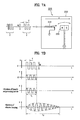
- FIGs . 7A and 7B are circuit diagrams schematically illustrating the construction of the vibrator.
- the vibrator 200 includes a coil 210, a linearly reciprocating mover 230 having a permanent magnet disposed at a predetermined position thereof, and a vibrator housing 250.
- the control part 700 recognizes that one of the key buttons has been touched, and transmits to the vibrator driving part 300 a specific signal indicating that one of the key buttons has been touched. Upon receipt, the vibrator driving part 300 generates a voltage square wave V corresponding to the specific signal.
- a magnetic field of the coil 210 is changed based on the voltage square wave V.
- the change of the magnetic field of the coil 210 affects the permanent magnet of the linearly reciprocating mover 230.
- the linearly reciprocating mover 230 is linearly reciprocated in a direction indicated by x depending upon the change of the magnetic field of the coil 210, and therefore, the linearly reciprocating mover 230 impacts against the vibrator housing 250. Consequently, the vibrator 200 generates vibration corresponding to the inputted voltage square wave, i.e., vibration pulse in the direction of x.
- the generation time of the magnetic field ⁇ of the coil 210 is equal to the application time of the voltage square wave V.
- the moving time of the linearly reciprocating mover 230 is equal to the generation time of the magnetic field ⁇ of the coil 210. Consequently, the application time of the voltage square wave V, the generation time of the magnetic field ⁇ of the coil 210, and the moving time of the linearly reciprocating mover 230 are the same as indicated by t1 in FIG. 7B .
- the magnitude M of the voltage square wave V is constant. Therefore, the magnitude of the magnetic field of the coil 210 and the magnitude of the vibration of the linearly reciprocating mover 230 are constant during t1.
- the vibration time t 2 of the vibrator housing 250 (see FIG. 7A ) generated by the impact of the linearly reciprocating mover 230 against the vibrator housing 250 is approximately 10 times compared to the application time of the voltage square wave V due to the resonance of the vibrator housing 250.
- An experiment revealed that, when a voltage square wave having t 1 3 ms is inputted, the vibration time t 2 of the vibrator housing 250 is 30 ms.
- the magnitude of the vibration of the vibrator housing 250 is gradually increased during t 1 , and, after expiration of which gradually decreases. This means that the magnitude of the vibration pulse generated by the vibrator can be controlled by the number of cycle repetitions of the voltage square wave.
- the vibration, pulse of the vibrator housing allows for the user of the terminal to feel instantaneous vibration sensation when the user of the terminal pushes one of the key buttons on the touch screen.
- Embodiment 3-1 Vibrator positioned at the center of the first display part
- FIG. 8 is a front view illustrating a preferred position of a vibrator 200 in a mobile terminal according to Embodiment 3-1
- FIGs. 9A and 9B are sectional views taken along line II-II' of FIG. 8 .
- the vibrator 200 may be positioned at the center of the lower surface, i.e. backside, of the first display part.
- the surface of the first display part facing the interior of the housing is referred to as a "lower surface" of the first display part.
- the vibrator 200 is constructed such that the vibration direction of the vibrator 200 is perpendicular to the lower surface of the first display part.
- vibration is applied to the center of the first display part.
- the vibration can be uniformly distributed on the first display part to provide the user of the terminal with more accurate feedback with respect to user input.
- vibration can be directly transmitted to a stylus pen or a finger of the user of the terminal through the first display part. With this, the vibration can be transmitted more accurately to the user of the terminal.
- the vibrator 200 is directly attached to the lower surface of the first display part 100 as described above, the vibrator may be constructed such that the vibrator is attached to the inside of the first housing of the first terminal body while being spaced apart from the first display part 100, as shown in FIG. 9B .
- the vibrator 200 does not directly apply vibration to the first display part 100, but applies vibration to the stylus pen or the finger of the user of the terminal through the first housing 14. Consequently, a possibility of the first display part 100 being damaged due to the vibration is reduced.
- Embodiment 3-2 Vibrator positioned at the edge of the first display part
- FIG. 10 is a front view illustrating a preferred position of a vibrator 200 in a mobile terminal according to Embodiment 3-2, and FIGs. 11A and 11B are sectional views taken along line III-III' of FIG. 10 .
- the vibrator 200 may be positioned at the edge of the lower surface of the first display part.
- the vibrator 200 is constructed such that the vibration direction of the vibrator 200 is perpendicular to the lower surface of the first display part like the previously described Embodiment 3-2.
- an advantage of this embodiment is that the lower surface of the first display part can be vibrated even by vibration having a magnitude less than the case of FIG. 8 .
- the vibrator 200 may be directly attached to the lower surface of the first display part 100 as shown in FIG. 11A .
- the vibrator 200 may be attached to the inside of the first housing as shown in FIG. 11B .
- the attachment of the vibrator 200 has been previously described in detail in connection with Embodiment 3-1, and therefore, a detailed description thereof will not be given below.
- the voltage square wave V which is applied to the vibrator 200 by the vibrator driving part 300 such that a user of the terminal can feel instantaneous vibration sensation whenever the user of the terminal touches one of the key buttons on the touch screen, will be described in more detail with reference to FIG. 7 .
- the inventors have performed experiments on several subjects.
- the objective of the experiments were to determine whether the subjects were able to experience and/or feel the same or similar vibration provided to to the first display part 100 by the vibrator 200 to that of the the conventional push-type buttons (e.g., tactile sensation corresponding to feel of the key buttons pressed downward/inward) while varying the frequency and the number of cycle repetitions of the voltage square wave V.
- the conventional push-type buttons e.g., tactile sensation corresponding to feel of the key buttons pressed downward/inward
- a term "voltage square wave V" refers to a voltage waveform generated by the vibrator driving part when a user of the terminal touches the touch screen once.
- the voltage waveform is formed in the shape of a square wave.
- the voltage waveform is not limited to the shape of a square wave but may also be formed in other shapes, such as a sawtooth wave, a pulse wave, or a sine wave.
- a term "number of cycle repetitions of voltage square wave” refers to a number of repetitions of one cycle T of the voltage square wave V.
- the number of cycle repetitions of the voltage square wave V shown in FIG. 7B is 3.
- frequency f of voltage square wave refers to a reciprocal of time corresponding to one cycle T of the voltage square wave V.
- magnitude M of voltage square wave refers to a peak-to-peak amplitude of the voltage square wave V.
- the results of the experiment revealed that the magnitude of instantaneous vibration which a user of the terminal feels on the first display part is mainly influenced by the magnitude of the voltage square wave.
- the magnitude of instantaneous vibration is partially influenced by the number of cycle repetitions of voltage square wave and the frequency of voltage square wave. This is because resonance may be generated between the voltage square wave and natural vibration frequency based on the material of the first display part and the material of the housing surrounding the first display part.
- the experiment was carried out using a terminal having a vibrator provided to a touch screen, which is made of glass and surrounded by a housing made of polycarbonate, according to the present invention.
- the experiments have revealed that it is preferable to have the following results.
- the voltage square wave generated by the vibrator driving part has a number of cycle repetitions equaling 9 or less and a frequency of 300 Hz to 700 Hz
- the subjects experienced instantaneous vibration sensation similar to tactile sensation obtained when the push type button(s) is actually pushed (e.g., conventional push-type buttons).
- the voltage square wave generated by the vibrator driving part preferably has a number of cycle repetitions equaling 5 or less and a frequency of 400 Hz to 600 Hz
- the subjects experienced instantaneous vibration sensation further similar to tactile sensation obtained when one of the push type buttons is actually pushed.
- the results of the experiment are results obtained from actual experience of several subjects. Consequently, it should be noted that the results of the experiment are difficult to be calculated as accurate numerical data.
- the vibrator 200 may be constructed to provide voltage square wave, associated with a first key button, having at least one of the number of cycle repetitions, the frequency, and the magnitude different from the number of cycle repetitions, frequency, and magnitude of the voltage square wave associated with a second key button. For example, if the user touches "5" key button which has a number of cycle repetitions equaling 3, and thereafter, the user touches "9" key button whose number of cycle repetitions equals 2, then the number of cycle repetitions associated with the selected key buttons are different. The same comparison can be made for the frequency and the magnitude. Furthermore, when the user of the terminal pushes the key buttons, the user of the terminal can perceive different instantaneous vibration sensations based on different voltage square waves without watching the second display part, whereby the user of the terminal can confirm which buttons have been pushed.
- the vibrator may be constructed such that additional instantaneous vibration sensation indicating input error can be outputted from the vibrator. Alternatively, no response or no feedback can be provided to indicate error in pressing or touching the key buttons.
- the mobile terminal having the touch screen according to the previous embodiments has the following effects.
- the user of the terminal When a user of the terminal correctly touches the key buttons on the touch screen of the terminal, the user of the terminal can perceive, in the form of visual sensation, hearing sensation, and/or vibration sensation, that the key buttons have been correctly touched, and therefore, it is possible to more easily and conveniently manipulate the key buttons on the terminal having the touch screen. Especially, when the user of the terminal touches the key buttons on the touch screen of the terminal, the user can perceive, in the form of vibration sensation, that the key buttons have been correctly touched, and therefore, it is possible for the user of the terminal to confirm whether the key buttons have been touched without watching an additional display part.
- the user of the terminal pushes key buttons on the touch screen of the terminal, the user can feel or experience instantaneous vibration sensation similar to tactile sensation obtained when the conventional mechanical push buttons are actually pushed. Consequently, it is possible for any user experienced in using the conventional push-type mechanical buttons to easily manipulate the key buttons on the touch screen.
Claims (12)
- Ensemble d'écran tactile comprenant :une partie d'affichage (100) de type écran tactile destinée à afficher des parties d'entrée utilisées pour délivrer en entrée des informations ;un vibreur (200) destiné à fournir une vibration à la partie d'affichage lorsqu'une opération d'entrée est réalisée par l'intermédiaire des parties d'entrée ; etune partie de pilotage (300) de vibreur destinée à piloter le vibreur, dans lequel la partie de pilotage de vibreur délivre une onde carrée de tension au vibreur pour faire vibrer instantanément la partie d'affichage, caractérisé en ce que l'onde carrée de tension présente un nombre de répétitions de cycles de 5 ou moins qui présentent la même amplitude, et présente une fréquence de 300 Hz à 700 Hz.
- Ensemble d'écran tactile selon la revendication 1, dans lequel le vibreur (200) comprend :une bobine (210) ;un dispositif de mouvement de va-et-vient linéaire (230) construit pour être déplacé linéairement en va-et-vient en fonction de la charge d'un champ magnétique généré à partir de la bobine ; etun logement (250) de vibreur construit pour entourer la bobine et le dispositif de mouvement de va-et-vient, et dans lequellorsque l'onde carrée de tension est appliquée à la bobine, le dispositif de mouvement de va-et-vient linéaire se heurte contre le logement de vibreur pour générer une impulsion de vibration, d'où il résulte qu'une vibration est délivrée à la partie d'affichage (100).
- Ensemble d'écran tactile selon la revendication 1 ou 2, dans lequel le vibreur (200) est positionné au niveau d'un côté arrière de la partie d'affichage.
- Ensemble d'écran tactile selon la revendication 3, dans lequel le vibreur (200) est positionné au niveau du bord du côté arrière.
- Ensemble d'écran tactile selon la revendication 3, dans lequel le vibreur (200) est positionné au niveau du centre du côté arrière.
- Ensemble d'écran tactile selon l'une quelconque des revendications 2 à 5, dans lequel l'impulsion de vibration est appliquée perpendiculairement au plan de la partie d'affichage.
- Ensemble d'écran tactile selon l'une quelconque des revendications 2 à 6, dans lequel l'amplitude de l'impulsion de vibration est commandée par le nombre de répétitions de cycles de l'onde carrée de tension.
- Ensemble d'écran tactile selon l'une quelconque des revendications 1 à 7, dans lequel l'onde carrée de tension est construite d'une manière telle qu'au moins l'un parmi le nombre de répétitions de cycles, la fréquence et l'amplitude de l'onde carrée de tension est différent en fonction des types de touches pressées par un utilisateur.
- Terminal comprenant :un ensemble d'écran tactile comprenant une partie d'affichage (100) de type écran tactile destinée à afficher des parties d'entrée utilisées pour qu'un utilisateur délivre des informations en entrée, un vibreur (200) destiné à délivrer une vibration à la partie d'affichage lorsque des informations sont délivrées en entrée par l'intermédiaire des parties d'entrée, et une partie (300) de pilotage de vibreur destinée à piloter le vibreur, la partie de pilotage de vibreur délivrant une onde carrée de tension au vibreur de façon à faire instantanément vibrer la partie d'affichage ; etun logement (14) formant l'apparence externe du terminal ;caractérisé en ce que l'onde carrée de tension présente un nombre de répétitions de cycles de 5 ou moins qui présentent la même amplitude, et présente une fréquence de 300 Hz à 700 Hz.
- Terminal selon la revendication 9, dans lequel le vibreur (200) est positionné d'une manière telle que le vibreur est en contact avec l'intérieur du logement (14) alors que le vibreur est espacé d'un côté arrière de la partie d'affichage (100).
- Procédé d'entrée de touches sur un terminal comportant un écran tactile, comprenant les étapes consistant à :a) afficher des parties d'entrée sur un écran tactile ;b) reconnaître qu'un utilisateur a réalisé une opération d'entrée par l'intermédiaire des parties d'entrée ; etc) lorsque l'opération d'entrée est détectée, délivrer en entrée une onde carrée de tension correspondant à l'opération d'entrée vers un vibreur pour amener l'écran tactile à vibrer instantanément ;caractérisé en ce que l'onde carrée de tension présente un nombre de répétitions de cycles de 5 ou moins qui présentent la même amplitude, et présente une fréquence de 300 Hz à 700 Hz.
- Procédé d'entrée de touches selon la revendication 11, dans lequel l'onde carrée de tension est construite d'une manière telle qu'au moins l'un parmi le nombre de répétitions de cycles, la fréquence et l'amplitude de l'onde carrée de tension est différent en fonction des types de parties d'entrée manipulées par l'utilisateur du terminal.
Applications Claiming Priority (2)
| Application Number | Priority Date | Filing Date | Title |
|---|---|---|---|
| KR1020050074193A KR100710362B1 (ko) | 2005-08-12 | 2005-08-12 | 터치스크린을 구비한 이동통신단말기 |
| KR1020050085259A KR100731019B1 (ko) | 2005-09-13 | 2005-09-13 | 터치스크린 어셈블리, 이를 구비한 이동통신단말기, 및이에 키입력을 하는 방법 |
Publications (2)
| Publication Number | Publication Date |
|---|---|
| EP1752860A1 EP1752860A1 (fr) | 2007-02-14 |
| EP1752860B1 true EP1752860B1 (fr) | 2015-03-18 |
Family
ID=37189030
Family Applications (1)
| Application Number | Title | Priority Date | Filing Date |
|---|---|---|---|
| EP06016840.8A Expired - Fee Related EP1752860B1 (fr) | 2005-08-12 | 2006-08-11 | Terminal mobile avec écran tactile à rétroaction haptique et procédé correspondant |
Country Status (3)
| Country | Link |
|---|---|
| US (2) | US20070035527A1 (fr) |
| EP (1) | EP1752860B1 (fr) |
| JP (1) | JP4925767B2 (fr) |
Families Citing this family (26)
| Publication number | Priority date | Publication date | Assignee | Title |
|---|---|---|---|---|
| US20080237402A1 (en) * | 2005-12-19 | 2008-10-02 | Marc Ausman | Aircraft trim safety system and backup controls |
| KR100846497B1 (ko) * | 2006-06-26 | 2008-07-17 | 삼성전자주식회사 | 디스플레이 버튼 입력 장치 및 이를 구비한 휴대용전자장치 |
| US7791594B2 (en) * | 2006-08-30 | 2010-09-07 | Sony Ericsson Mobile Communications Ab | Orientation based multiple mode mechanically vibrated touch screen display |
| US20080146256A1 (en) * | 2006-12-19 | 2008-06-19 | Jeffrey Charles Hawkins | Sharing data during a voice call using a mobile communications device, and associated user interface |
| DE602007012211D1 (de) * | 2007-06-08 | 2011-03-10 | Research In Motion Ltd | Haptische Anzeige für ein elektronisches Handgerät |
| KR101320504B1 (ko) * | 2007-07-10 | 2013-10-22 | 엘지전자 주식회사 | 휴대 단말기 |
| JP4857213B2 (ja) * | 2007-07-25 | 2012-01-18 | チームラボ株式会社 | 携帯電話 |
| US8509854B2 (en) | 2007-09-18 | 2013-08-13 | Lg Electronics Inc. | Mobile terminal and method of controlling operation of the same |
| KR101499546B1 (ko) * | 2008-01-17 | 2015-03-09 | 삼성전자주식회사 | 터치 스크린 장치의 디스플레이 영역 제어 방법, 장치, 및기록매체 |
| US8103298B2 (en) * | 2008-05-22 | 2012-01-24 | Motorola Solutions, Inc. | Multiple PTT functionality |
| GB2462465B (en) | 2008-08-08 | 2013-02-13 | Hiwave Technologies Uk Ltd | Touch sensitive device |
| US8750938B2 (en) * | 2008-09-29 | 2014-06-10 | Microsoft Corporation | Glow touch feedback for virtual input devices |
| US8508475B2 (en) * | 2008-10-24 | 2013-08-13 | Microsoft Corporation | User interface elements positioned for display |
| JP2010286986A (ja) * | 2009-06-10 | 2010-12-24 | Funai Electric Co Ltd | 携帯端末装置 |
| CN101697470B (zh) * | 2009-10-30 | 2011-05-25 | 青岛海信移动通信技术股份有限公司 | 一种控制线性马达振动的方法 |
| KR20110099415A (ko) * | 2010-03-02 | 2011-09-08 | 삼성전자주식회사 | 휴대용 단말기의 다이얼링 장치 및 방법 |
| US8878655B2 (en) * | 2010-05-04 | 2014-11-04 | Nokia Corporation | Vibration mechanism for user interface module |
| TW201222604A (en) * | 2010-11-17 | 2012-06-01 | Inventec Corp | Electronic device |
| JP5887830B2 (ja) * | 2010-12-10 | 2016-03-16 | 株式会社ニコン | 電子機器及び振動方法 |
| TWI433136B (zh) * | 2011-07-29 | 2014-04-01 | Univ Nat Central | 顯示系統以及方法 |
| US9311426B2 (en) * | 2011-08-04 | 2016-04-12 | Blackberry Limited | Orientation-dependent processing of input files by an electronic device |
| KR101320176B1 (ko) | 2011-12-26 | 2013-10-23 | 삼성전기주식회사 | 햅틱 피드백 디바이스 |
| JP2013200863A (ja) | 2012-02-23 | 2013-10-03 | Panasonic Corp | 電子機器 |
| KR102035305B1 (ko) | 2013-01-15 | 2019-11-18 | 삼성전자주식회사 | 휴대 단말에서 햅틱 효과를 제공하는 방법 및 기계로 읽을 수 있는 저장 매체 및 휴대 단말 |
| KR102133365B1 (ko) | 2013-05-09 | 2020-07-13 | 삼성전자 주식회사 | 정보를 사용자에게 제공하기 위한 전자 장치 |
| JP7099660B2 (ja) * | 2020-06-23 | 2022-07-12 | 株式会社村田製作所 | 振動装置及び電子機器 |
Family Cites Families (38)
| Publication number | Priority date | Publication date | Assignee | Title |
|---|---|---|---|---|
| US6624803B1 (en) * | 1995-10-20 | 2003-09-23 | Wisconsin Alumni Research Foundation | Interface for electronic devices providing improved access for people with disabilities |
| US6028593A (en) * | 1995-12-01 | 2000-02-22 | Immersion Corporation | Method and apparatus for providing simulated physical interactions within computer generated environments |
| US6667738B2 (en) * | 1998-01-07 | 2003-12-23 | Vtech Communications, Ltd. | Touch screen overlay apparatus |
| US5977867A (en) * | 1998-05-29 | 1999-11-02 | Nortel Networks Corporation | Touch pad panel with tactile feedback |
| US6184868B1 (en) * | 1998-09-17 | 2001-02-06 | Immersion Corp. | Haptic feedback control devices |
| US6429846B2 (en) | 1998-06-23 | 2002-08-06 | Immersion Corporation | Haptic feedback for touchpads and other touch controls |
| CA2278832A1 (fr) * | 1999-01-06 | 2000-07-06 | Vtech Communications, Ltd. | Feuille superposee sur ecran tactile |
| JP3949912B2 (ja) * | 2000-08-08 | 2007-07-25 | 株式会社エヌ・ティ・ティ・ドコモ | 携帯型電子機器、電子機器、振動発生器、振動による報知方法および報知制御方法 |
| US6906697B2 (en) * | 2000-08-11 | 2005-06-14 | Immersion Corporation | Haptic sensations for tactile feedback interface devices |
| KR100500129B1 (ko) * | 2001-03-02 | 2005-07-11 | 삼성전기주식회사 | 진동 음향 변환장치 |
| US6963762B2 (en) * | 2001-05-23 | 2005-11-08 | Nokia Corporation | Mobile phone using tactile icons |
| JP2003005912A (ja) * | 2001-06-20 | 2003-01-10 | Hitachi Ltd | タッチパネル付きディスプレイ装置及び表示方法 |
| JP3798287B2 (ja) * | 2001-10-10 | 2006-07-19 | Smk株式会社 | タッチパネル入力装置 |
| US20030080947A1 (en) * | 2001-10-31 | 2003-05-01 | Genest Leonard J. | Personal digital assistant command bar |
| DE10154643A1 (de) | 2001-11-07 | 2003-05-15 | Siemens Ag | Bedienvorrichtung für einen bildschirmgesteuerten Prozess |
| FI115861B (fi) * | 2001-11-12 | 2005-07-29 | Myorigo Oy | Menetelmä ja laite palautteen generoimiseksi |
| CN1666169B (zh) * | 2002-05-16 | 2010-05-05 | 索尼株式会社 | 输入方法和输入装置 |
| US6879842B2 (en) * | 2002-05-31 | 2005-04-12 | Lavaflow, Llp | Foldable wireless communication device functioning as a cellular telephone and a personal digital assistant |
| FI20021162A0 (fi) * | 2002-06-14 | 2002-06-14 | Nokia Corp | Elektroninen laite ja menetelmä sen näppäimistön hallintaan |
| JP4500485B2 (ja) * | 2002-08-28 | 2010-07-14 | 株式会社日立製作所 | タッチパネルを備えた表示装置 |
| JP3937982B2 (ja) * | 2002-08-29 | 2007-06-27 | ソニー株式会社 | 入出力装置および入出力装置を有する電子機器 |
| CN1320421C (zh) * | 2002-12-04 | 2007-06-06 | 皇家飞利浦电子股份有限公司 | 具有触摸检测能力的用于设备的控制面板及其控制方法 |
| JP4177142B2 (ja) * | 2003-03-10 | 2008-11-05 | 富士通コンポーネント株式会社 | 座標入力装置及び駆動装置 |
| JP4213539B2 (ja) * | 2003-08-12 | 2009-01-21 | 富士通コンポーネント株式会社 | 座標入力装置 |
| EP1517224A3 (fr) | 2003-09-16 | 2007-02-21 | Volkswagen Aktiengesellschaft | Dispositif d'affichage sensible au toucher |
| JP4338513B2 (ja) * | 2003-12-26 | 2009-10-07 | アルパイン株式会社 | 入力制御装置及び入力受付方法 |
| JP2005190290A (ja) * | 2003-12-26 | 2005-07-14 | Alpine Electronics Inc | 入力制御装置及び入力応答方法 |
| US7401300B2 (en) * | 2004-01-09 | 2008-07-15 | Nokia Corporation | Adaptive user interface input device |
| JP4279171B2 (ja) * | 2004-02-13 | 2009-06-17 | 富士通コンポーネント株式会社 | 平面板振動装置及びこれを用いたスイッチ |
| JP3857278B2 (ja) * | 2004-04-06 | 2006-12-13 | Smk株式会社 | タッチパネル入力装置 |
| JP2005328379A (ja) * | 2004-05-14 | 2005-11-24 | Toshiba Corp | 入力ガイド表示操作システム |
| KR100735299B1 (ko) * | 2004-06-23 | 2007-07-03 | 삼성전기주식회사 | 수직진동자 |
| JP2006039837A (ja) * | 2004-07-26 | 2006-02-09 | Smk Corp | タッチパネル入力装置 |
| JP4439351B2 (ja) * | 2004-07-28 | 2010-03-24 | アルパイン株式会社 | 振動付与機能付きタッチパネル入力装置および操作入力に対する振動付与方法 |
| JP2006048302A (ja) * | 2004-08-03 | 2006-02-16 | Sony Corp | 圧電複合装置、その製造方法、その取扱方法、その制御方法、入出力装置及び電子機器 |
| US20060079842A1 (en) * | 2004-10-13 | 2006-04-13 | Liebel-Flarsheim Company | Powerhead control in a power injection system |
| JP4368787B2 (ja) * | 2004-12-15 | 2009-11-18 | Smk株式会社 | パルス幅変調信号生成装置及びパルス幅変調信号の生成方法 |
| US7616192B2 (en) * | 2005-07-28 | 2009-11-10 | Avago Technologies Ecbu Ip (Singapore) Pte. Ltd. | Touch device and method for providing tactile feedback |
-
2006
- 2006-08-11 EP EP06016840.8A patent/EP1752860B1/fr not_active Expired - Fee Related
- 2006-08-11 US US11/502,482 patent/US20070035527A1/en not_active Abandoned
- 2006-08-14 JP JP2006221334A patent/JP4925767B2/ja not_active Expired - Fee Related
-
2009
- 2009-04-06 US US12/419,175 patent/US20090197648A1/en not_active Abandoned
Also Published As
| Publication number | Publication date |
|---|---|
| JP4925767B2 (ja) | 2012-05-09 |
| EP1752860A1 (fr) | 2007-02-14 |
| US20090197648A1 (en) | 2009-08-06 |
| JP2007052785A (ja) | 2007-03-01 |
| US20070035527A1 (en) | 2007-02-15 |
Similar Documents
| Publication | Publication Date | Title |
|---|---|---|
| EP1752860B1 (fr) | Terminal mobile avec écran tactile à rétroaction haptique et procédé correspondant | |
| JP3987182B2 (ja) | 情報表示装置および操作入力装置 | |
| CN1921667B (zh) | 触摸屏组件、移动终端及相应的键输入方法 | |
| US8378796B2 (en) | Portable terminal | |
| EP1748350B1 (fr) | Dispositif tactile et procédé permettant une rétroaction tactile | |
| US20190179415A1 (en) | Tactile sensation providing apparatus and control method for tactile sensation providing apparatus | |
| CN105446646B (zh) | 基于虚拟键盘的内容输入方法、装置及触控设备 | |
| EP3306449B1 (fr) | Vibrateur linéaire fournissant une rétroaction haptique localisée et généralisée | |
| KR100846497B1 (ko) | 디스플레이 버튼 입력 장치 및 이를 구비한 휴대용전자장치 | |
| US8179378B2 (en) | Input apparatus and control method of input apparatus | |
| US8330737B2 (en) | Input apparatus | |
| US9927874B2 (en) | Input apparatus and control method for input apparatus | |
| US20160085308A1 (en) | Orientation adjustable multi-channel haptic device | |
| JP2004530200A (ja) | ラップトップコンピュータ及びその他の携帯用機器のための触感インターフェイス | |
| KR20120047982A (ko) | 입력 장치 및 입력 장치의 제어 방법 | |
| US20140028592A1 (en) | Haptic Input Stylus | |
| CN103927017A (zh) | 多模触觉反馈系统 | |
| CN101523329A (zh) | 多模触觉反馈系统 | |
| KR100980855B1 (ko) | 이종 액츄에이터로 햅틱 피드백을 제공하는 휴대기기 및 그제공방법 | |
| KR20100107997A (ko) | 펜형태의 촉감 제시 장치와 그를 이용한 촉감 인터페이스 시스템 | |
| JPH11162277A (ja) | タッチ式入力装置、携帯電子機器、リモコン装置及びキー入力装置 | |
| US11276377B2 (en) | Electronic apparatus | |
| JP2006065507A (ja) | 振動伝達機構、振動波形データ作成方法、触覚機能付き入力装置及び電子機器 | |
| JP2010087736A (ja) | 情報端末装置 | |
| KR20070030528A (ko) | 터치스크린 어셈블리, 이를 구비한 이동통신단말기, 및이에 키입력을 하는 방법 |
Legal Events
| Date | Code | Title | Description |
|---|---|---|---|
| PUAI | Public reference made under article 153(3) epc to a published international application that has entered the european phase |
Free format text: ORIGINAL CODE: 0009012 |
|
| AK | Designated contracting states |
Kind code of ref document: A1 Designated state(s): AT BE BG CH CY CZ DE DK EE ES FI FR GB GR HU IE IS IT LI LT LU LV MC NL PL PT RO SE SI SK TR |
|
| AX | Request for extension of the european patent |
Extension state: AL BA HR MK YU |
|
| 17P | Request for examination filed |
Effective date: 20070813 |
|
| 17Q | First examination report despatched |
Effective date: 20070910 |
|
| AKX | Designation fees paid |
Designated state(s): DE FR GB IT |
|
| RAP1 | Party data changed (applicant data changed or rights of an application transferred) |
Owner name: LG ELECTRONICS INC. |
|
| REG | Reference to a national code |
Ref country code: DE Ref legal event code: R079 Ref document number: 602006044807 Country of ref document: DE Free format text: PREVIOUS MAIN CLASS: G06F0003000000 Ipc: H04M0001020000 |
|
| GRAP | Despatch of communication of intention to grant a patent |
Free format text: ORIGINAL CODE: EPIDOSNIGR1 |
|
| INTG | Intention to grant announced |
Effective date: 20141014 |
|
| RIC1 | Information provided on ipc code assigned before grant |
Ipc: H04M 1/23 20060101ALI20141006BHEP Ipc: G06F 3/01 20060101ALI20141006BHEP Ipc: H04M 1/02 20060101AFI20141006BHEP Ipc: G06F 3/0488 20130101ALI20141006BHEP |
|
| GRAS | Grant fee paid |
Free format text: ORIGINAL CODE: EPIDOSNIGR3 |
|
| GRAA | (expected) grant |
Free format text: ORIGINAL CODE: 0009210 |
|
| AK | Designated contracting states |
Kind code of ref document: B1 Designated state(s): DE FR GB IT |
|
| REG | Reference to a national code |
Ref country code: GB Ref legal event code: FG4D |
|
| REG | Reference to a national code |
Ref country code: DE Ref legal event code: R096 Ref document number: 602006044807 Country of ref document: DE Effective date: 20150430 |
|
| REG | Reference to a national code |
Ref country code: DE Ref legal event code: R097 Ref document number: 602006044807 Country of ref document: DE |
|
| PG25 | Lapsed in a contracting state [announced via postgrant information from national office to epo] |
Ref country code: IT Free format text: LAPSE BECAUSE OF FAILURE TO SUBMIT A TRANSLATION OF THE DESCRIPTION OR TO PAY THE FEE WITHIN THE PRESCRIBED TIME-LIMIT Effective date: 20150318 |
|
| PLBE | No opposition filed within time limit |
Free format text: ORIGINAL CODE: 0009261 |
|
| STAA | Information on the status of an ep patent application or granted ep patent |
Free format text: STATUS: NO OPPOSITION FILED WITHIN TIME LIMIT |
|
| 26N | No opposition filed |
Effective date: 20151221 |
|
| REG | Reference to a national code |
Ref country code: FR Ref legal event code: PLFP Year of fee payment: 11 |
|
| REG | Reference to a national code |
Ref country code: FR Ref legal event code: PLFP Year of fee payment: 12 |
|
| REG | Reference to a national code |
Ref country code: FR Ref legal event code: PLFP Year of fee payment: 13 |
|
| PGFP | Annual fee paid to national office [announced via postgrant information from national office to epo] |
Ref country code: DE Payment date: 20180705 Year of fee payment: 13 Ref country code: FR Payment date: 20180710 Year of fee payment: 13 |
|
| PGFP | Annual fee paid to national office [announced via postgrant information from national office to epo] |
Ref country code: GB Payment date: 20180706 Year of fee payment: 13 |
|
| REG | Reference to a national code |
Ref country code: DE Ref legal event code: R119 Ref document number: 602006044807 Country of ref document: DE |
|
| GBPC | Gb: european patent ceased through non-payment of renewal fee |
Effective date: 20190811 |
|
| PG25 | Lapsed in a contracting state [announced via postgrant information from national office to epo] |
Ref country code: FR Free format text: LAPSE BECAUSE OF NON-PAYMENT OF DUE FEES Effective date: 20190831 Ref country code: DE Free format text: LAPSE BECAUSE OF NON-PAYMENT OF DUE FEES Effective date: 20200303 |
|
| PG25 | Lapsed in a contracting state [announced via postgrant information from national office to epo] |
Ref country code: GB Free format text: LAPSE BECAUSE OF NON-PAYMENT OF DUE FEES Effective date: 20190811 |