EP1752815A1 - Method of manufacturing an optical system - Google Patents
Method of manufacturing an optical system Download PDFInfo
- Publication number
- EP1752815A1 EP1752815A1 EP05291716A EP05291716A EP1752815A1 EP 1752815 A1 EP1752815 A1 EP 1752815A1 EP 05291716 A EP05291716 A EP 05291716A EP 05291716 A EP05291716 A EP 05291716A EP 1752815 A1 EP1752815 A1 EP 1752815A1
- Authority
- EP
- European Patent Office
- Prior art keywords
- optical system
- equation
- function
- virtual
- manufacturing
- Prior art date
- Legal status (The legal status is an assumption and is not a legal conclusion. Google has not performed a legal analysis and makes no representation as to the accuracy of the status listed.)
- Withdrawn
Links
Images



Classifications
-
- G—PHYSICS
- G02—OPTICS
- G02C—SPECTACLES; SUNGLASSES OR GOGGLES INSOFAR AS THEY HAVE THE SAME FEATURES AS SPECTACLES; CONTACT LENSES
- G02C7/00—Optical parts
- G02C7/02—Lenses; Lens systems ; Methods of designing lenses
-
- B—PERFORMING OPERATIONS; TRANSPORTING
- B29—WORKING OF PLASTICS; WORKING OF SUBSTANCES IN A PLASTIC STATE IN GENERAL
- B29D—PRODUCING PARTICULAR ARTICLES FROM PLASTICS OR FROM SUBSTANCES IN A PLASTIC STATE
- B29D11/00—Producing optical elements, e.g. lenses or prisms
- B29D11/00009—Production of simple or compound lenses
-
- B—PERFORMING OPERATIONS; TRANSPORTING
- B29—WORKING OF PLASTICS; WORKING OF SUBSTANCES IN A PLASTIC STATE IN GENERAL
- B29D—PRODUCING PARTICULAR ARTICLES FROM PLASTICS OR FROM SUBSTANCES IN A PLASTIC STATE
- B29D11/00—Producing optical elements, e.g. lenses or prisms
- B29D11/00951—Measuring, controlling or regulating
- B29D11/00961—Measuring, controlling or regulating using microprocessors or computers
- B29D11/00971—Measuring, controlling or regulating using microprocessors or computers using CNC machining to make mould surfaces
-
- G—PHYSICS
- G02—OPTICS
- G02B—OPTICAL ELEMENTS, SYSTEMS OR APPARATUS
- G02B3/00—Simple or compound lenses
-
- G—PHYSICS
- G02—OPTICS
- G02B—OPTICAL ELEMENTS, SYSTEMS OR APPARATUS
- G02B3/00—Simple or compound lenses
- G02B3/0081—Simple or compound lenses having one or more elements with analytic function to create variable power
-
- G—PHYSICS
- G02—OPTICS
- G02B—OPTICAL ELEMENTS, SYSTEMS OR APPARATUS
- G02B3/00—Simple or compound lenses
- G02B3/10—Bifocal lenses; Multifocal lenses
-
- G—PHYSICS
- G02—OPTICS
- G02C—SPECTACLES; SUNGLASSES OR GOGGLES INSOFAR AS THEY HAVE THE SAME FEATURES AS SPECTACLES; CONTACT LENSES
- G02C7/00—Optical parts
-
- G—PHYSICS
- G02—OPTICS
- G02C—SPECTACLES; SUNGLASSES OR GOGGLES INSOFAR AS THEY HAVE THE SAME FEATURES AS SPECTACLES; CONTACT LENSES
- G02C7/00—Optical parts
- G02C7/02—Lenses; Lens systems ; Methods of designing lenses
- G02C7/024—Methods of designing ophthalmic lenses
- G02C7/028—Special mathematical design techniques
-
- G—PHYSICS
- G02—OPTICS
- G02C—SPECTACLES; SUNGLASSES OR GOGGLES INSOFAR AS THEY HAVE THE SAME FEATURES AS SPECTACLES; CONTACT LENSES
- G02C7/00—Optical parts
- G02C7/02—Lenses; Lens systems ; Methods of designing lenses
- G02C7/06—Lenses; Lens systems ; Methods of designing lenses bifocal; multifocal ; progressive
- G02C7/061—Spectacle lenses with progressively varying focal power
-
- G—PHYSICS
- G06—COMPUTING OR CALCULATING; COUNTING
- G06F—ELECTRIC DIGITAL DATA PROCESSING
- G06F30/00—Computer-aided design [CAD]
-
- G—PHYSICS
- G02—OPTICS
- G02C—SPECTACLES; SUNGLASSES OR GOGGLES INSOFAR AS THEY HAVE THE SAME FEATURES AS SPECTACLES; CONTACT LENSES
- G02C2202/00—Generic optical aspects applicable to one or more of the subgroups of G02C7/00
- G02C2202/08—Series of lenses, lens blanks
Definitions
- An aspect of the invention relates to a method of manufacturing an optical system, and more particularly a progressive power lens.
- Other aspects of the invention relate to a method of manufacturing a semi-finished optical system, a computer-program product for manufacturing an optical system, a computer-program product for manufacturing a semi-finished optical system.
- Progressive power lenses typically comprise a far-vision region having one refractive power, a near-vision region having a different refractive power, and an intermediate progressive region.
- semi-finished progressive lens blanks are provided by lens manufacturer to prescription labs.
- a semi-finished progressive lens blank comprises a front progressive surface and a back spherical surface ("standard semi-finished lens blank").
- a standard semi-finished lens blank having suitable optical characteristics is then selected based on a prescription.
- the back spherical surface is finally machined and polished by the prescription lab (based on the base curve) so as to obtain a sphero-torical surface complying with the prescription.
- a progressive power lens complying with the prescription is thus obtained.
- the invention relates to a method of manufacturing an optical system OS, the optical system OS being identified by a function OF, the optical system OS comprising a first part F1 defined by a first equation EF1 and a second part F2 defined by a second equation EF2, the method comprising:
- the optical system OS can be, for example, a progressive power lens.
- the function OF can be, for example, an optical function OF or a part of an optical function OF.
- the first part and the second part can be, for example, any volume or surface of the optical system.
- the first manufacturing step M1 defines the opto-geometric characteristics EF1(x,y,z) of the first part F1 of the semi-finished optical system.
- the semi-finished optical system can advantageously be used to manufacture a second optical system OS2, having a second optical function OF2.
- the optical system does not depend on the characteristics of the semi-finished optical system only. This allows a manufacturer to stock semi-finished optical system independently of the optical system. Thus, the invention enables to enhance the stock management in a manufacturing process.
- the invention related to a method of manufacturing an optical system (OS), the optical system (OS) being identified by a function (OF), the optical system (OS) comprising a first part (F1) defined by a first equation (EF1) and a second part (F2) defined by a second equation (EF2), the method comprising:
- the method further comprises the following steps:
- the optical function OF is substantially equal to the virtual optical function VOF
- the first equation EF1 is substantially equal to the first virtual equation
- the second virtual equation EVF2 is a physical solution for the second equation EF2.
- the virtual optical function can, for example, be modified by using prescription data provided by an Eye Care Practitioner.
- the optical function can be more adapted to the characteristics of the eye.
- the method according to the invention allows to store a generic virtual function and to modify it by a specific modification.
- the generating step according to the invention comprises selecting the first virtual equation EVF1 in a database.
- the method further comprises an equation modifying step, in which the first virtual equation EVF1 is modified by using a first modifying function N1 so as to obtained a first modified equation EV'F1, the first equation EF1 being substantially equal to the first modified equation EVF'1.
- the secret data can be, for example, data relating to the geometry of the progressive face of the semi-finished lens blank.
- the secret data can also be, for example, any opto-geometric characteristics in particular the equations of the surfaces defining the two parts, or the optical index of the two parts, or any combination thereof.
- the secret data are split up between the first and the second part of the optical system.
- the secret data is split up between the first and the second part of the optical system.
- the invention also concerns a computer program product for a data-processing device, the computer program product comprising a set of instructions which, when loaded into the data-processing device, causes the device to perform the steps of the method according to the invention, for an optical system, or for a semi-finished optical system.
- Embodiments of the present invention may include apparatuses for performing the operations herein.
- This apparatus may be specially constructed for the desired purposes, or it may comprise a general purpose computer or Digital Signal Processor ("DSP") selectively activated or reconfigured by a computer program stored in the computer.
- DSP Digital Signal Processor
- Such a computer program may be stored in a computer readable storage medium, such as, but is not limited to, any type of disk including floppy disks, optical disks, CD-ROMs, magnetic-optical disks, read-only memories (ROMs), random access memories (RAMs) electrically programmable read-only memories (EPROMs), electrically erasable and programmable read only memories (EEPROMs), magnetic or optical cards, or any other type of media suitable for storing electronic instructions, and capable of being coupled to a computer system bus.
- a computer readable storage medium such as, but is not limited to, any type of disk including floppy disks, optical disks, CD-ROMs, magnetic-optical disks, read-only memories (ROMs), random access memories (RAMs) electrically programmable read-only memories (EPROMs), electrically erasable and programmable read only memories (EEPROMs), magnetic or optical cards, or any other type of media suitable for storing electronic instructions, and capable of being coupled to a computer system bus.
- the term "virtual" is used to define an optical system which is calculated and generated by a computer. According to the present invention, the virtual face are not intended to be manufactured as such.
- optical function OF of an optical system OS can be defined as follows:
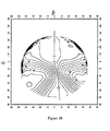
- FIG. 1A An example of graphical representation of an array of power PUI and of an array of astigmatism AST is shown at figure 1A and figure 1B. These arrays (PUI,AST) have been obtained for a design suitable for a user with emmetropia addition 2. Illustrated figure ID, the gaze direction is defined by two angles, latitude ⁇ and longitude ⁇ from the center of rotation of the eye. The aberrations are calculated for each gaze direction to obtain array MAT and array PUI.
- the prescription data PRES are known by the one skilled in the art and are related to usual data provided by an Eye Care Practitioner such as sphere, cylinder, axe, prism, power addition. Additional data provided by an optician can be used if available.
- the optical function can be obtained by adding the prescribed values of power and astigmatism to specific arrays, respectively PUI and AST.
- these specific arrays can be given, for example, for each addition and ametropia type (myopia, hyperopia, emmetropia).
- the optical index can be chosen as a constant.
- the method of manufacturing a progressive power lens OS comprises a manufacturing step M1 in which a semi-finished optical system comprising a first part F1 is manufactured.
- the first part F1 is defined by a first equation EF1, which is for example the equation of an outer surface.
- a manufactured semi-finished optical system MSFOS is thus obtained.
- the equation of the second part EF2 is then determined in a calculation step CAL from the optical function and the equation of the first part EF1. Equations (5) and (4) are used to determine such an equation from the optical function OF and the equation of the first surface EF1.
- the calculation step CAL can be performed by using a ray-tracing method or optimization algorithms. These methods are known by the one skilled in the art, for example in the publication "Application of optimization in computer-aided ophthalmic lens design” ( P. Allione, F. Ahsbhs and G. Le Saux, in SPIE Vol. 3737, EUROPTO Conference on Design and Engineering of Optical Systems, Berlin, May 1999 ).
- the manufactured semi-finished optical system MSFOS is manufactured so as to obtain a second part of equation EF2.
- This can be done by any known method in the art of manufacturing lenses as described, for example, in the US granted patent referenced under grant number US 6, 558, 586 B1 , the content of which is incorporated by reference.
- the manufactured semi-finished optical system MSFOS further provided with a second part F2 of equation EF2 forms the optical system OS.
- the optical function OF of the optical system OS to be manufactured is based on a virtual optical function VOF.
- a virtual progressive power lens VOS having a virtual optical function VOF is generated.
- the virtual progressive power lens VOS comprises a first virtual face VF1 which is defined by a first equation EVF1.
- the virtual progressive power lens VOS further comprises a second virtual face VF2 which is defined by a second equation EVF2.
- the virtual optical function VOF can then be modified in a modification step MOD to obtain an optical function OF.
- the modified virtual optical system MVOS has a modified first face MVF1 and a modified second face MVF2.
- the modification MOD can be made by using prescription data from an Eye Care Practitioner to be adapted to the prescription.
- the modification MOD can be without limitation an isometric transformation such as offset, symmetry, translation, or a morphing of the virtual optical system VOS.
- the modified virtual optical system is the virtual optical system, and the optical function is substantially equal to the virtual optical function.
- a preset virtual optical functions VOF can then be retrieved directly from a database to define the opto-geomtric characteristics of the virtual optical system.
- the modification step MOD can then be used to adapt this virtual optical function VOF to the needs of a particular wearer.
- a database containing virtual optical function is available, one can choose, among the database, a virtual optical function corresponding to the general characteristics of the wearer. A more accurate adaptation of this virtual optical function is then performed in a modification step MOD to adapt the optical system OS to the more precise needs of the wearer.
- the method of manufacturing a progressive power lens OS comprises a first manufacturing step M1 and a second manufacturing step M2. It further comprises a virtual optical system generating step GEN and a first modifying step MS1.
- a virtual progressive power lens VOS having a virtual optical function VOF is generated.
- the virtual progressive power lens VOS comprises a first virtual face VF1 which is defined by a first equation EVF1.
- the virtual progressive power lens VOS further comprises a second virtual face VF2 which is defined by a second equation EVF2.
- EVF1(x,y) and EVF2(x,y) can be defined, for example, such that the optical function VF of the virtual progressive power lens VOS is substantially equal to the optical function OF of the progressive power lens OS.
- a first surface F1 of a semi-finished optical system SFOS is manufactured.
- a semi-finished optical system SFOS is thus obtained.
- the manufacturing of the semi-finished optical system SFOS can be done by any known method in the art of manufacturing lenses as described, for example, in the US granted patent referenced under grant number US 6, 558, 586 B1 , the content of which is incorporated by reference.
- the first encrypting function N1(x,y) is a secret data which is only known by the one implementing the method of manufacturing of the invention.
- the method of manufacturing a progressive power lens further comprises a second manufacturing step M2.
- the second manufacturing step M2 comprises a second modifying sub-step MS2 and a second manufacturing sub-step MAN2.
- constraints can be added in the choice of the first and second encrypting functions N1 and N2. Such constraints can be linked, for example, to calculation time or other constraints defined by manufacturing laboratories.
- a second face F2 of the semi-finished optical system SFOS is manufactured so as to obtain the progressive power lens OS.
- the surface of the second face F2 of the progressive power lens OS is defined by the second modified equation EV'F2(x,y).
- first and the second face F1, F2 of the progressive power lens OS must comply with the constraints defined by the optical function OF
- the preferred second encryption function N2(x,y) is substantially equal to N1(x,y).
- the first encrypting function and the second encrypting N1 and N2 only depend on the optical system OS to be manufactured.
- the same semi-finished optical system SFOS could also be used to manufacture an optical system OS2 having an optical function OF2.
- the stock management of semi-finished optical systems SFOS can thus be done by associating the semi-finished optical systems SFOS with the optical system to be manufactured.
- the stock management of semi-finished optical systems SFOS can be done independently of the final optical system by choosing suitable modifying functions. The stock management in the manufacturing process is therefore improved.
- the first part and the second part can correspond to any volume or surface of the optical system.
- the first part and the second part can be, for example, a first face and a second face of the optical system corresponding to front and back optical surfaces, or a first volume and a second volume of the optical system corresponding to a back part and a front part of the system.
- the opto-geometric characteristics can be, for example, the equations of the surfaces defining the two parts, or the optical index of the two parts, or any combination thereof.
- the calculation of the second equation EF2 from the function OF, and the first equation EF1 in the calculation step CAL can be performed by any algorithm known in the art of calculation on optical systems.
- the modification MOD can be without limitation an isometric transformation such as offset, symmetry, translation, or a morphing of the virtual optical system VOS.
- the first modifying function N1 can be, for example, an encryption function or a noise function.
- the noise function can be any discontinuous function such as, for example, a diffractive function, in particular, a Fresnel function.
- the discontinuous function has a spatial frequency cut-off which is preferably less than 1 mm -1 (1/1 millimeter).
- the noise function can also be, for example, a white noise function.
- the first function N1 can be any function arranged to modify the opto-geometric characteristics of the parts or surfaces of an optical system.
- the detailed description also illustrates a method of manufacturing an optical system OS, wherein the second manufacturing step M2 comprises the following sub-steps:
- the second modifying function N2 can be, for example, an encryption function or noise function, in particular a white noise function
- the function F was an optical function OF. But the function F can be also a part of such optical function OF.
- the function F can be defined by the array of power and astigmatism MAT.
- the function F can be any function arranged to identify or define an optical system OS.
- the optical system OS was a progressive power lens. It has to be understood that it can also be any type of optical system, for example, a lens or a multifocal lens.
- the optical system can also be any a device for either concentrating or diverging light.
- the optical system can also be any analogous device used with other types of electromagnetic radiation such as a microwave lens for example made from paraffin wax.
- the optical system can also be a part of an imaging system such as monocular, binoculars, telescope, spotting scope, telescoping gun sight, microscope and camera (photographic lens).
- the optical system can also be dielectric lens for radio astronomy and radar systems to refract electromagnetic radiation into a collector antenna.
Landscapes
- Physics & Mathematics (AREA)
- Ophthalmology & Optometry (AREA)
- Health & Medical Sciences (AREA)
- General Physics & Mathematics (AREA)
- Engineering & Computer Science (AREA)
- Optics & Photonics (AREA)
- General Health & Medical Sciences (AREA)
- Mechanical Engineering (AREA)
- Manufacturing & Machinery (AREA)
- Microelectronics & Electronic Packaging (AREA)
- Mathematical Physics (AREA)
- Theoretical Computer Science (AREA)
- General Engineering & Computer Science (AREA)
- Geometry (AREA)
- Evolutionary Computation (AREA)
- Computer Hardware Design (AREA)
- Eyeglasses (AREA)
- Testing Of Optical Devices Or Fibers (AREA)
- Optical Communication System (AREA)
- Architecture (AREA)
- Software Systems (AREA)
Abstract
The invention relates to a method of manufacturing an optical system (OS), the optical system (OS) being identified by a function (OF), the optical system (OS) comprising a first part (F1) defined by a first equation (EF1) and a second part (F2) defined by a second equation (EF2), the method comprising:
- a calculation step (CAL), in which the second equation EF2 is calculated from the function OF, and the first equation EF1;
- a first manufacturing step (M1), in which a semi-finished optical system (SFOS) comprising the first part (F1) is manufactured so as to obtain a manufactured semi-finished optical system (MSFOS); and
- a second manufacturing step (M2), in which the manufactured semi-finished optical system (MSFOS) is manufactured so as to be further provided with a second part (F2) defined by the second equation (EF2) and to obtain the optical system (OS).
- a calculation step (CAL), in which the second equation EF2 is calculated from the function OF, and the first equation EF1;
- a first manufacturing step (M1), in which a semi-finished optical system (SFOS) comprising the first part (F1) is manufactured so as to obtain a manufactured semi-finished optical system (MSFOS); and
- a second manufacturing step (M2), in which the manufactured semi-finished optical system (MSFOS) is manufactured so as to be further provided with a second part (F2) defined by the second equation (EF2) and to obtain the optical system (OS).
Description
- An aspect of the invention relates to a method of manufacturing an optical system, and more particularly a progressive power lens. Other aspects of the invention relate to a method of manufacturing a semi-finished optical system, a computer-program product for manufacturing an optical system, a computer-program product for manufacturing a semi-finished optical system.
- Progressive power lenses typically comprise a far-vision region having one refractive power, a near-vision region having a different refractive power, and an intermediate progressive region.
- According to a common practice, semi-finished progressive lens blanks are provided by lens manufacturer to prescription labs. Generally a semi-finished progressive lens blank comprises a front progressive surface and a back spherical surface ("standard semi-finished lens blank"). A standard semi-finished lens blank having suitable optical characteristics is then selected based on a prescription. The back spherical surface is finally machined and polished by the prescription lab (based on the base curve) so as to obtain a sphero-torical surface complying with the prescription. A progressive power lens complying with the prescription is thus obtained.
- According to an aspect, the invention relates to a method of manufacturing an optical system OS, the optical system OS being identified by a function OF, the optical system OS comprising a first part F1 defined by a first equation EF1 and a second part F2 defined by a second equation EF2, the method comprising:
- a calculation step CAL, in which the second equation EF2 is calculated from the function OF, and the first equation EF1;
- a first manufacturing step M1, in which a semi-finished optical system SFOS comprising the first part F1 is manufactured so as to obtain a manufactured semi-finished optical system MSFOS; and
- a second manufacturing step M2, in which the manufactured semi-finished optical system MSFOS is manufactured so as to be further provided with a second part F2 defined by the second equation EF2 and to obtain the optical system OS.
- The optical system OS can be, for example, a progressive power lens. The function OF can be, for example, an optical function OF or a part of an optical function OF. The first part and the second part can be, for example, any volume or surface of the optical system. The optical function OF of an optical system OS is defined as a function of the opto-geometric properties of the optical system OS, which can be written, for a two parts system comprising a first part F 1 and a second part F2,

EF1(x,y,z) defining the opto-geometric properties of part F 1
EF2(x,y,z) defining the opto-geometric properties of part F2 - According to the invention, the first manufacturing step M1 defines the opto-geometric characteristics EF1(x,y,z) of the first part F1 of the semi-finished optical system. Thus, by choosing a suitable second part F2, the invention allows the manufacture of an optical system such that OF = h (EF1(x,y,z), EF2(x,y,z)).
- In other words, if a semi-finished optical system was manufactured according to the first manufacturing step M1, and was firstly intended to be modified to manufacture a first optical system OS1 having an optical function OF1, the semi-finished optical system can advantageously be used to manufacture a second optical system OS2, having a second optical function OF2. In this respect, the second equation EF2 has just to be chosen such that OF2= h (EF1(x,y,z)), EF2(x,y,z))), and not OF1= h (EF1(x,y,z)), EF2(x,y,z))).
- Therefore, the optical system does not depend on the characteristics of the semi-finished optical system only. This allows a manufacturer to stock semi-finished optical system independently of the optical system. Thus, the invention enables to enhance the stock management in a manufacturing process.
- According to another aspect the invention related to a method of manufacturing an optical system (OS), the optical system (OS) being identified by a function (OF), the optical system (OS) comprising a first part (F1) defined by a first equation (EF1) and a second part (F2) defined by a second equation (EF2), the method comprising:
- a calculation step (CAL), in which the second equation (EF2) is calculated from the function (OF), and the first equation (EF1);
- a first manufacturing step (M1), in which a semi-finished optical system (SFOS) comprising the first part (F2) is manufactured so as to obtain a manufactured semi-finished optical system (MSFOS); and
- a second manufacturing step (M2), in which the manufactured semi-finished optical system (MSFOS) is manufactured so as to be further provided with a first part (F1) defined by the first equation (EF1) and to obtain the optical system (OS).
- According to another aspect of the invention, the method further comprises the following steps:
- a generating step GEN, in which a virtual optical system VOS is used to generate a virtual function VOF, the virtual optical system VOS comprising a first virtual part VF1 defined by a first virtual equation EVF1 and a second virtual part VF2 defined by a second virtual equation EVF2, the first virtual equation EVF1 and the second virtual equation EVF2 defining the virtual function VOF;
- a modification step MOD, in which the virtual function VOF is modified so as obtain the function OF.
- By generating a virtual optical system and defining the optical function as a modification of a virtual optical function, one can ensure that the calculation step CAL according to the invention has a solution. For example, if the optical function OF is substantially equal to the virtual optical function VOF, and the first equation EF1 is substantially equal to the first virtual equation, the second virtual equation EVF2 is a physical solution for the second equation EF2.
- The virtual optical function can, for example, be modified by using prescription data provided by an Eye Care Practitioner. Thus, by modifying this virtual function, the optical function can be more adapted to the characteristics of the eye.
- Moreover, by defining the optical function from the modification of a virtual optical function, memory space is saved. In fact, instead of storing the optical functions for each specific client, the method according to the invention allows to store a generic virtual function and to modify it by a specific modification.
- According to another aspect, the generating step according to the invention comprises selecting the first virtual equation EVF1 in a database.
- By selecting the first virtual equation in a database of known virtual equations, one can ensure that the performances of the optical system can be those of an existing system.
- Moreover, by avoiding the calculation of a specific first equation and by selecting the equation in a database, calculation time is saved.
- According to another aspect of the invention, the method further comprises an equation modifying step, in which the first virtual equation EVF1 is modified by using a first modifying function N1 so as to obtained a first modified equation EV'F1, the first equation EF1 being substantially equal to the first modified equation EVF'1.
- The first modifying function N1 can be, for example, arranged to modify the opto-geometric characteristics of the first virtual part VF1 such that:

- By providing standard semi finished optical system to prescription labs, it is quite easy to obtain data that might be considered by the lens manufacturer as secret data. This can be achieved, for example, by using well-known three dimensional measuring systems. The secret data can be, for example, data relating to the geometry of the progressive face of the semi-finished lens blank. The secret data can also be, for example, any opto-geometric characteristics in particular the equations of the surfaces defining the two parts, or the optical index of the two parts, or any combination thereof.
- By using the first modifying function in order to modify the first parts of a virtual optical system VOS in order to manufacture a semi finished optical system and an optical system having the required optical function, the secret data are split up between the first and the second part of the optical system. Thus it is more difficult to deduce the secret data by using a measuring system.
- The invention also concerns a computer program product for a data-processing device, the computer program product comprising a set of instructions which, when loaded into the data-processing device, causes the device to perform the steps of the method according to the invention, for an optical system, or for a semi-finished optical system.
- The subject matter regarded as the invention is particularly pointed out and distinctly claimed in the concluding portion of the specification. The invention, however, both as to organization and method of operation, together with objects, features and advantages thereof, may best be understood by reference to the following detailed description when read with the accompanied drawings in which:
- FIG. 1A shows a graphical representation of an array of power;
- FIG. 1B shows a graphical representation of an array of astigmatism;
- FIG. 1C shows an example of data used to determine the optical function of an optical system;
- FIG. 1D shows the longitude and latitude data used to represent the array of power and the array of astigmatism;
- FIG. 2 is a block diagram of the manufacturing process according to the invention;
- FIG. 3 is a block diagram of an embodiment of the manufacturing process according to the invention;
- FIG 4A schematically illustrates a virtual system generated according to the present invention;
- FIG 4B schematically illustrates a modified virtual system according to the present invention;
- FIG. 5A schematically illustrates a virtual system generated according to the present invention;
- FIG. 5B schematically illustrates a semi-finished optical system manufactured according to the present invention;
- FIG. 5C schematically illustrates an optical system manufactured according to the present invention;
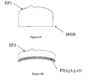
- FIG 6A corresponds to a semi-finished optical system as in FIG 5B.
- FIG 6B schematically illustrates an optical system manufactured according to the present invention wherein the optical index has been modified to comply with the optical function.
- Unless specifically stated otherwise, as apparent from the following discussions, it is appreciated that throughout the specification discussions utilizing terms such as "computing", "calculating" "generating", or the like, refer to the action and/or processes of a computer or computing system, or similar electronic computing device, that manipulate and/or transform data represented as physical, such as electronic, quantities within the computing system's registers and/or memories into other data similarly represented as physical quantities within the computing system's memories, registers or other such information storage, transmission or display devices.
- Embodiments of the present invention may include apparatuses for performing the operations herein. This apparatus may be specially constructed for the desired purposes, or it may comprise a general purpose computer or Digital Signal Processor ("DSP") selectively activated or reconfigured by a computer program stored in the computer. Such a computer program may be stored in a computer readable storage medium, such as, but is not limited to, any type of disk including floppy disks, optical disks, CD-ROMs, magnetic-optical disks, read-only memories (ROMs), random access memories (RAMs) electrically programmable read-only memories (EPROMs), electrically erasable and programmable read only memories (EEPROMs), magnetic or optical cards, or any other type of media suitable for storing electronic instructions, and capable of being coupled to a computer system bus.
- The processes and displays presented herein are not inherently related to any particular computer or other apparatus. Various general purpose systems may be used with programs in accordance with the teachings herein, or it may prove convenient to construct a more specialized apparatus to perform the desired method. The desired structure for a variety of these systems will appear from the description below. In addition, embodiments of the present invention are not described with reference to any particular programming language. It will be appreciated that a variety of programming languages may be used to implement the teachings of the inventions as described herein.
- For the purpose of the present application, the term "virtual" is used to define an optical system which is calculated and generated by a computer. According to the present invention, the virtual face are not intended to be manufactured as such.
-


MAT being an array of power and astigmatism;
PUI being an array of power;
AST being an array of astigmatism;
PRES being prescription data;
F1 and F2 being the equation of the first face and of the second face of the optical system; and
n being the optical index. - It has to be noted that if the optical index is a constant, the optical function OF of an optical system can be defined as follows:

- An example of graphical representation of an array of power PUI and of an array of astigmatism AST is shown at figure 1A and figure 1B. These arrays (PUI,AST) have been obtained for a design suitable for a user with
emmetropia addition 2. Illustrated figure ID, the gaze direction is defined by two angles, latitude α and longitude β from the center of rotation of the eye. The aberrations are calculated for each gaze direction to obtain array MAT and array PUI. - The prescription data PRES are known by the one skilled in the art and are related to usual data provided by an Eye Care Practitioner such as sphere, cylinder, axe, prism, power addition. Additional data provided by an optician can be used if available.
- Advantageously, but not limited to, in the ophthalmic field the optical function can be obtained by adding the prescribed values of power and astigmatism to specific arrays, respectively PUI and AST. In general, these specific arrays can be given, for example, for each addition and ametropia type (myopia, hyperopia, emmetropia).
- In order to better understand the invention, a method of manufacturing an optical system OS in the form of a progressive power lens will now be described in a detailed manner. In this particular example, the optical index can be chosen as a constant. The optical function of an optical system can thus be defined as follows:

- As illustrated figure 2, the method of manufacturing a progressive power lens OS comprises a manufacturing step M1 in which a semi-finished optical system comprising a first part F1 is manufactured. The first part F1 is defined by a first equation EF1, which is for example the equation of an outer surface. A manufactured semi-finished optical system MSFOS is thus obtained.
- According to the invention, the equation of the second part EF2 is then determined in a calculation step CAL from the optical function and the equation of the first part EF1. Equations (5) and (4) are used to determine such an equation from the optical function OF and the equation of the first surface EF1.
- The calculation step CAL can be performed by using a ray-tracing method or optimization algorithms. These methods are known by the one skilled in the art, for example in the publication "Application of optimization in computer-aided ophthalmic lens design" (P. Allione, F. Ahsbhs and G. Le Saux, in SPIE Vol. 3737, EUROPTO Conference on Design and Engineering of Optical Systems, Berlin, May 1999).
- In a second manufacturing step M2, the manufactured semi-finished optical system MSFOS is manufactured so as to obtain a second part of equation EF2. This can be done by any known method in the art of manufacturing lenses as described, for example, in the US granted patent referenced under grant number
US 6, 558, 586 B1 , the content of which is incorporated by reference. - The manufactured semi-finished optical system MSFOS further provided with a second part F2 of equation EF2 forms the optical system OS.
- In a particular embodiment, the optical function OF of the optical system OS to be manufactured is based on a virtual optical function VOF.
- In a virtual optical system generating step GEN, a virtual progressive power lens VOS having a virtual optical function VOF is generated. As illustrated in figure 4A and 4B, the virtual progressive power lens VOS comprises a first virtual face VF1 which is defined by a first equation EVF1. The virtual progressive power lens VOS further comprises a second virtual face VF2 which is defined by a second equation EVF2.
- The virtual optical function VOF can then be modified in a modification step MOD to obtain an optical function OF. The modified virtual optical system MVOS has a modified first face MVF1 and a modified second face MVF2.
- The modification MOD can be made by using prescription data from an Eye Care Practitioner to be adapted to the prescription.
- The modification MOD can be without limitation an isometric transformation such as offset, symmetry, translation, or a morphing of the virtual optical system VOS.
- If the modification is chosen as the identity function, the modified virtual optical system is the virtual optical system, and the optical function is substantially equal to the virtual optical function.
- A preset virtual optical functions VOF can then be retrieved directly from a database to define the opto-geomtric characteristics of the virtual optical system.
- The modification step MOD can then be used to adapt this virtual optical function VOF to the needs of a particular wearer.
- For example, if a database containing virtual optical function is available, one can choose, among the database, a virtual optical function corresponding to the general characteristics of the wearer. A more accurate adaptation of this virtual optical function is then performed in a modification step MOD to adapt the optical system OS to the more precise needs of the wearer.
- As illustrated in figure 3, according to another aspect, the method of manufacturing a progressive power lens OS comprises a first manufacturing step M1 and a second manufacturing step M2. It further comprises a virtual optical system generating step GEN and a first modifying step MS1.
- In the virtual optical system generating step GEN, a virtual progressive power lens VOS having a virtual optical function VOF is generated. As illustrated in figure 5A, the virtual progressive power lens VOS comprises a first virtual face VF1 which is defined by a first equation EVF1. The virtual progressive power lens VOS further comprises a second virtual face VF2 which is defined by a second equation EVF2. The first equation EVF1 and the second equation EVF2 are chosen such that:

- EVF1(x,y) and EVF2(x,y) can be defined, for example, such that the optical function VF of the virtual progressive power lens VOS is substantially equal to the optical function OF of the progressive power lens OS.
- As illustrated in figure 3, in a first modifying step MS1, the first equation EVF1(x,y) is modified, for example, by adding a first encryption function N1(x,y) so as to obtain a modified equation EV'F1 defined as follows:

- Then, in a first manufacturing step M1, a first surface F1 of a semi-finished optical system SFOS is manufactured. The equation EF 1 of the first surface F 1 is defined as follows:

- A semi-finished optical system SFOS is thus obtained. The manufacturing of the semi-finished optical system SFOS can be done by any known method in the art of manufacturing lenses as described, for example, in the US granted patent referenced under grant number
US 6, 558, 586 B1 , the content of which is incorporated by reference. It has to be noted that, the first encrypting function N1(x,y) is a secret data which is only known by the one implementing the method of manufacturing of the invention. The first encrypting function N1 can be more generally any secret transformation of the function EVF1(x,y) such that
- Thus when analyzing the semi-finished optical system SFOS, it will be more difficult for a third party to access to the secret data EVF1(x,y) and EVF2(x,y).
- As illustrated in figure 3, the method of manufacturing a progressive power lens further comprises a second manufacturing step M2. The second manufacturing step M2 comprises a second modifying sub-step MS2 and a second manufacturing sub-step MAN2.
- In the second modifying sub-step MS2, the second equation EVF2(x,y) is modified, for example, by adding a second encrypting function N2(x,y) so as to obtained a second modified equation EV'F2(x,y) defined as follows:

- The second encryption function N2(x,y) is chosen such that

- It has to be understood that other constraints can be added in the choice of the first and second encrypting functions N1 and N2. Such constraints can be linked, for example, to calculation time or other constraints defined by manufacturing laboratories.
- Then in a second manufacturing sub-step MAN2, a second face F2 of the semi-finished optical system SFOS is manufactured so as to obtain the progressive power lens OS. The surface of the second face F2 of the progressive power lens OS is defined by the second modified equation EV'F2(x,y).
- It is understood that the first and the second face F1, F2 of the progressive power lens OS must comply with the constraints defined by the optical function OF
- When the optical function is a function of the difference of the equations of the surfaces, i.e OF = h(EF2(x,y) - EF1(x,y)), the preferred second encryption function N2(x,y) is substantially equal to N1(x,y).
- According to an advantage of the invention, the first encrypting function and the second encrypting N1 and N2 only depend on the optical system OS to be manufactured. A semi-finished optical system SFOS provided with a first face F1 of equation EF1(x,y)=N1[EVF1(x,y)] can thus be used, for example, to manufacture an optical system OS1 having an optical function OF 1. But the same semi-finished optical system SFOS could also be used to manufacture an optical system OS2 having an optical function OF2. In this case, the second encrypting function N2 has to be chosen such that OF2(x,y)= h (N1(EVF1(x,y)), N2(EVF2(x,y))). The stock management of semi-finished optical systems SFOS can thus be done by associating the semi-finished optical systems SFOS with the optical system to be manufactured. Alternatively the stock management of semi-finished optical systems SFOS can be done independently of the final optical system by choosing suitable modifying functions. The stock management in the manufacturing process is therefore improved.
- The detailed description hereinbefore with reference to the drawings illustrates a method of manufacturing an optical system OS, the optical system OS being identified by a function OF, the optical system OS comprising a first part F1 defined by a first equation EF 1 and a second part F2 defined by a second equation EF2, the method comprising:
- a calculation step CAL, in which the second equation EF2 is calculated from the function OF, and the first equation EF1;
- a first manufacturing step M1, in which a semi-finished optical system SFOS comprising the first part F1 is manufactured so as to obtain a manufactured semi-finished optical system MSFOS; and
- a second manufacturing step M2, in which the manufactured semi-finished optical system MSFOS is manufactured so as to be further provided with a second part F2 defined by the second equation EF2 and to obtain the optical system OS.
- The aforementioned characteristics can be implemented in numerous different manners. In order to illustrate this, some alternatives are briefly indicated.
- The first part and the second part can correspond to any volume or surface of the optical system.
- The first part and the second part can be, for example, a first face and a second face of the optical system corresponding to front and back optical surfaces, or a first volume and a second volume of the optical system corresponding to a back part and a front part of the system. The opto-geometric characteristics can be, for example, the equations of the surfaces defining the two parts, or the optical index of the two parts, or any combination thereof.
- The calculation of the second equation EF2 from the function OF, and the first equation EF1 in the calculation step CAL can be performed by any algorithm known in the art of calculation on optical systems.
- The detailed description hereinbefore with reference to the drawings also illustrates a method that further comprises the following steps:
- a generating step GEN, in which a virtual optical system VOS is used to generate a virtual function VOF, the virtual optical system VOS comprising a first virtual part VF1 defined by a first virtual equation EVF1 and a second virtual part VF2 defined by a second virtual equation EVF2, the first virtual equation EVF1 and the second virtual equation EVF2 defining the virtual function VOF;
- a modification step MOD, in which the virtual function VOF is modified so as obtain the function OF.
- The modification MOD can be without limitation an isometric transformation such as offset, symmetry, translation, or a morphing of the virtual optical system VOS.
- The detailed description hereinbefore with reference to the drawings also illustrates a method which further comprises an equation modifying step, in which the first virtual equation EVF1 is modified by using a first modifying function N1 so as to obtained a first modified equation EV'F1, the first equation EF1 being substantially equal to the first modified equation EVF'1.
- The first modifying function N1 can be, for example, an encryption function or a noise function. The noise function can be any discontinuous function such as, for example, a diffractive function, in particular, a Fresnel function. Advantageously, the discontinuous function has a spatial frequency cut-off which is preferably less than 1 mm-1 (1/1 millimeter). The noise function can also be, for example, a white noise function. More generally the first function N1 can be any function arranged to modify the opto-geometric characteristics of the parts or surfaces of an optical system.
- The detailed description also illustrates a method of manufacturing an optical system OS, wherein the second manufacturing step M2 comprises the following sub-steps:
- a second modifying step MS2, in which the second virtual equation EVF2 is modified by using a second modifying function N2 so as to obtain a second modified equation EV'F2, the first modifying function N1 and the second modifying function N2 being defined in such a manner that the optical system can be identified by the function OF, and
- a second manufacturing step MAN2, in which the second part F2 of the semi-finished optical system SFOS is manufactured so as to obtain the optical system OS, the second equation EF2 of the second part F2 being substantially equal to the second modified equation EV'F2.
- The second modifying function N2 can be, for example, an encryption function or noise function, in particular a white noise function
- The functions described herein have been given in Cartesian coordinates (x,y,z) but it is understood that any coordinate can be used in the method according to the invention.
- In the detailed description, the equations of the surfaces of the systems have been modified. It has to be understood that any other opto-geometric characteristics can be modified. As illustrated figures 6A and 6B, the second modifying function N2 can be a modification of the optical index n2(x,y,z) in a part P2 of the modified semi finished optical system. This modification is indicated by dashed lines on figure 4B. Therefore, N2 has to be chosen such that OF1= h(N1(EVF1(x,y), N2(P2(x,y,z))).Any modification on the opto-geometric characteristics of the system, either for surface characteristics or volume characteristics can also be chosen, provided it respects the optical function OF or a specific part of the optical function OF of the optical system.
- Moreover, in the above examples, the function F was an optical function OF. But the function F can be also a part of such optical function OF. For example, for a given optical system having an optical function OF given by the equation OF (x,y,z)=MAT(x,y,z) +PRES, the function F can be defined by the array of power and astigmatism MAT. In such a case, the modifying functions N1 and N2 are such that MAT= g(EVF1, EVF2), and MAT=g(N1(EVF1), N2(EVF2)). More generally the function F can be any function arranged to identify or define an optical system OS.
- In the above mentioned description, the optical system OS was a progressive power lens. It has to be understood that it can also be any type of optical system, for example, a lens or a multifocal lens. The optical system can also be any a device for either concentrating or diverging light. The optical system can also be any analogous device used with other types of electromagnetic radiation such as a microwave lens for example made from paraffin wax. The optical system can also be a part of an imaging system such as monocular, binoculars, telescope, spotting scope, telescoping gun sight, microscope and camera (photographic lens).
- The optical system can also be dielectric lens for radio astronomy and radar systems to refract electromagnetic radiation into a collector antenna.
- The remarks made herein before demonstrate that the detailed description with reference to the drawings, illustrate rather than limit the invention. There are numerous alternatives, which fall within the scope of the appended claims. Any reference sign in a claim should not be construed as limiting the claim. The word "comprising" does not exclude the presence of other elements or steps than those listed in a claim. The word "a" or "an" preceding an element or step does not exclude the presence of a plurality of such elements or steps.
Claims (17)
- A method of manufacturing an optical system (OS), the optical system (OS) being identified by a function (OF), the optical system (OS) comprising a first part (F1) defined by a first equation (EF1) and a second part (F2) defined by a second equation (EF2), the method comprising:- a calculation step (CAL), in which the second equation (EF2) is calculated from the function (OF), and the first equation (EF1);- a first manufacturing step (M1), in which a semi-finished optical system (SFOS) comprising the first part (F1) is manufactured so as to obtain a manufactured semi-finished optical system (MSFOS); and- a second manufacturing step (M2), in which the manufactured semi-finished optical system (MSFOS) is manufactured so as to be further provided with a second part (F2) defined by the second equation (EF2) and to obtain the optical system (OS).
- The method of manufacturing an optical system (OS) according to claim 1, wherein the method further comprises the following steps:- a generating step (GEN), in which a virtual optical system (VOS) is used to generate a virtual function (VOF), the virtual optical system (VOS) comprising a first virtual part (VF1) defined by a first virtual equation (EVF1) and a second virtual part (VF2) defined by a second virtual equation (EVF2), the first virtual equation (EVF1) and the second virtual equation (EVF2) defining the virtual function (VOF);- a modification step (MOD), in which the virtual function (VOF) is modified so as obtain the function (OF)
- The method of manufacturing an optical system (OS), according to claim 2, wherein the virtual function (VOF) is substantially equal to the function (OF).
- The method of manufacturing an optical system (OS), according to claim 2, wherein the generating step comprises selecting the first virtual equation (EVF1) in a database.
- The method of manufacturing an optical system (OS) according to anyone of claims 2 to 4, wherein the method further comprises an equation modifying step, in which the first virtual equation (EVF1) is modified by using a first modifying function (N1) so as to obtained a first modified equation (EV'F1), the first equation (EF1) being substantially equal to the first modified equation (EVF'1).
- The method of manufacturing an optical system (OS) according to claim 5, wherein the second manufacturing step (M2) comprises the following sub-steps:- a second modifying step (MS2), in which the second virtual equation EVF2 is modified by using a second modifying function (N2) so as to obtain a second modified equation EV'F2, the first modifying function (N1) and the second modifying function (N2) being defined in such a manner that the optical system can be identified by the function (OF), and- a second manufacturing step (MAN2), in which the second part (F2) of the semi finished optical system (SFOS) is manufactured so as to obtain the optical system (OS), the second equation (EF2) of the second part (F2) being substantially equal to the second modified equation (EV'F2).
- A method according to claim 5, wherein the first virtual part (VF1) comprises a first volume of the virtual optical system (VOS), the first equation depending on opto-geometric characteristics of the first volume, and wherein the first modifying function (N1) modifies at least one of said opto-geometric characteristics.
- A method according to claim 6, wherein the second virtual part (VF2) comprises a second volume of the virtual optical system (VOS), the second equation depending on opto-geometric characteristics of the second volume, and wherein the second modifying function (N2) modifies at least one of said opto-geometric characteristics.
- A method according to claim 7 or 8, wherein the opto-geometric characteristics comprise at least one characteristic chosen among the equation of a surface and the optical index of a volume.
- A method according to claim 2, wherein the first virtual part (VF1) is a first virtual surface and the second virtual part (VF2) is a second virtual surface.
- A method according to claim 10, wherein the function (OF) depends on the difference of the equations of the first surface and the second surface, and wherein the second surface modifying function is substantially equal to the first surface modifying function.
- A method according to any one of the preceding claims wherein the function (OF) is an optical function (OF).
- A method according to any one of the preceding claims, wherein the optical system (OS) is a progressive power lens.
- An optical system comprising two parts, the optical system (OS) being identified by a function (OF), the optical system being manufactured with a method according to claim 1.
- A semi finished optical system (MSFOS) manufactured according to the first manufacturing step (M1) of claim 1 and intended to be modified by the second manufacturing step (M2) of claim 1.
- A computer program product for a data-processing device, the computer program product comprising a set of instructions which, when loaded into the data-processing device, causes the device to perform at least one of the steps of the method as claimed in claim 1 or 17.
- A method of manufacturing an optical system (OS), the optical system (OS) being identified by a function (OF), the optical system (OS) comprising a first part (F1) defined by a first equation (EF1) and a second part (F2) defined by a second equation (EF2), the method comprising:- a calculation step (CAL), in which the second equation (EF2) is calculated from the function (OF), and the first equation (EF1);- a first manufacturing step (M1), in which a semi-finished optical system (SFOS) comprising the first part (F2) is manufactured so as to obtain a manufactured semi-finished optical system (MSFOS); and- a second manufacturing step (M2), in which the manufactured semi-finished optical system (MSFOS) is manufactured so as to be further provided with a first part (F1) defined by the first equation (EF1) and to obtain the optical system (OS).
Priority Applications (12)
| Application Number | Priority Date | Filing Date | Title |
|---|---|---|---|
| EP05291716A EP1752815A1 (en) | 2005-08-11 | 2005-08-11 | Method of manufacturing an optical system |
| CN2006800295139A CN101243351B (en) | 2005-08-11 | 2006-08-01 | A method of manufacturing an optical system |
| KR1020087002963A KR101297289B1 (en) | 2005-08-11 | 2006-08-01 | Method Of Manufacturing An Optical System |
| BRPI0614811-5A BRPI0614811B1 (en) | 2005-08-11 | 2006-08-01 | MANUFACTURING PROCESS OF AN OPTICAL SYSTEM |
| US11/997,359 US8447573B2 (en) | 2005-08-11 | 2006-08-01 | Method of manufacturing an optical system |
| EP06809230.3A EP1920291B1 (en) | 2005-08-11 | 2006-08-01 | Method of manufacturing an optical system |
| CA2618336A CA2618336C (en) | 2005-08-11 | 2006-08-01 | Method of manufacturing an optical system |
| JP2008525662A JP2009505128A (en) | 2005-08-11 | 2006-08-01 | Method for manufacturing an optical system |
| AU2006277686A AU2006277686B2 (en) | 2005-08-11 | 2006-08-01 | Method of manufacturing an optical system |
| PCT/IB2006/003220 WO2007017766A2 (en) | 2005-08-11 | 2006-08-01 | Method of manufacturing an optical system |
| IL189122A IL189122A (en) | 2005-08-11 | 2008-01-30 | Optical system manufacturing method |
| US13/847,841 US20130218533A1 (en) | 2005-08-11 | 2013-03-20 | Method of Manufacturing an Optical System |
Applications Claiming Priority (1)
| Application Number | Priority Date | Filing Date | Title |
|---|---|---|---|
| EP05291716A EP1752815A1 (en) | 2005-08-11 | 2005-08-11 | Method of manufacturing an optical system |
Publications (1)
| Publication Number | Publication Date |
|---|---|
| EP1752815A1 true EP1752815A1 (en) | 2007-02-14 |
Family
ID=35500854
Family Applications (2)
| Application Number | Title | Priority Date | Filing Date |
|---|---|---|---|
| EP05291716A Withdrawn EP1752815A1 (en) | 2005-08-11 | 2005-08-11 | Method of manufacturing an optical system |
| EP06809230.3A Active EP1920291B1 (en) | 2005-08-11 | 2006-08-01 | Method of manufacturing an optical system |
Family Applications After (1)
| Application Number | Title | Priority Date | Filing Date |
|---|---|---|---|
| EP06809230.3A Active EP1920291B1 (en) | 2005-08-11 | 2006-08-01 | Method of manufacturing an optical system |
Country Status (10)
| Country | Link |
|---|---|
| US (2) | US8447573B2 (en) |
| EP (2) | EP1752815A1 (en) |
| JP (1) | JP2009505128A (en) |
| KR (1) | KR101297289B1 (en) |
| CN (1) | CN101243351B (en) |
| AU (1) | AU2006277686B2 (en) |
| BR (1) | BRPI0614811B1 (en) |
| CA (1) | CA2618336C (en) |
| IL (1) | IL189122A (en) |
| WO (1) | WO2007017766A2 (en) |
Cited By (5)
| Publication number | Priority date | Publication date | Assignee | Title |
|---|---|---|---|---|
| EP2028527A1 (en) * | 2007-12-28 | 2009-02-25 | Essilor International (Compagnie Générale D'Optique) | Method for selecting base-curves for an ophtalmic lens and related spectacle lens manufacturing method |
| WO2010133813A1 (en) | 2009-05-20 | 2010-11-25 | Essilor International (Compagnie Generale D'optique) | Single vision ophthalmic lens |
| EP2490065A1 (en) | 2011-02-18 | 2012-08-22 | ESSILOR INTERNATIONAL (Compagnie Générale d'Optique) | A method for determining target optical functions |
| WO2013117766A3 (en) * | 2012-02-10 | 2013-10-24 | Essilor International (Compagnie Generale D'optique) | System and method for real time segmentation |
| EP2486443B1 (en) * | 2009-10-07 | 2017-12-06 | Essilor International (Compagnie Générale D'Optique) | A lens and optical function determining method |
Families Citing this family (26)
| Publication number | Priority date | Publication date | Assignee | Title |
|---|---|---|---|---|
| EP2037314B1 (en) | 2007-12-28 | 2021-12-01 | Essilor International | A method and computer means for choosing spectacle lenses adapted to a frame |
| EP2028531B1 (en) | 2007-12-28 | 2016-05-04 | Essilor International (Compagnie Generale D'optique) | Method of selecting a semi-finished ophthalmic lens according to a given spectacle frame |
| ES2829678T3 (en) | 2007-12-28 | 2021-06-01 | Essilor Int | Method of calculating an optical system based on a given spectacle frame |
| EP2028529B1 (en) * | 2007-12-28 | 2020-09-09 | Essilor International | Method of calculating an optical system according to a given spectacle frame |
| EP2294474B1 (en) | 2008-06-12 | 2019-09-04 | Essilor International | Method for calculating a customized progressive addition surface; method for manufacturing a progressive addition lens |
| FR2938934B1 (en) | 2008-11-25 | 2017-07-07 | Essilor Int - Cie Generale D'optique | GLASSES OF EYEWEAR PROVIDING OPHTHALMIC VISION AND ADDITIONAL VISION |
| EP2199021A1 (en) * | 2008-12-22 | 2010-06-23 | Essilor International (Compagnie Générale D'Optique) | A method of and an apparatus for manufacturing an optical lens |
| FR2941060B1 (en) | 2009-01-13 | 2011-04-22 | Essilor Int | METHOD FOR DETERMINING AN ASPHERIZATION PATCH FOR AN OPHTHALMIC LENS |
| DE102009005206A1 (en) * | 2009-01-20 | 2010-07-22 | Rodenstock Gmbh | Variable progressive lens design |
| EP2270577A1 (en) | 2009-06-30 | 2011-01-05 | Essilor International (Compagnie Générale D'Optique) | Method of and apparatus for generating a surface of an optical lens |
| FR2950983A1 (en) | 2009-10-01 | 2011-04-08 | Essilor Int | METHOD FOR DETERMINING, OPTIMIZING AND MANUFACTURING OPHTHALMIC LENS AND OPHTHALMIC LENS ASSEMBLY |
| FR2956222B1 (en) | 2010-02-09 | 2012-07-27 | Essilor Int | PROGRESSIVE MULTIFOCAL OPHTHALMIC LENS |
| FR2956223B1 (en) | 2010-02-09 | 2012-04-13 | Essilor Int | PROGRESSIVE MULTIFOCAL OPHTHALMIC LENS |
| DE102011009473B4 (en) * | 2010-04-28 | 2022-03-17 | Rodenstock Gmbh | Computer-implemented method for calculating a spectacle lens with viewing-angle-dependent prescription data, device for calculating or optimizing a spectacle lens, computer program product, storage medium, method for manufacturing a spectacle lens, and use of a spectacle lens |
| FR2984197B1 (en) * | 2011-12-15 | 2014-01-03 | Essilor Int | PROCESS FOR TRANSFORMING AN INITIAL PROGRESSIVE SURFACE |
| US10345618B1 (en) | 2013-06-13 | 2019-07-09 | Essilor International | Method for determining a surface of an optical lens adapted to a spectacle frame |
| JP6675318B2 (en) * | 2014-04-01 | 2020-04-01 | エシロール・アンテルナシオナル | Multifocal spectacle lens configured to output an auxiliary image |
| KR102353079B1 (en) | 2014-04-02 | 2022-01-19 | 에씰로 앙터나시오날 | Method of calculating an optical system according to a given spectacle frame |
| US10247962B2 (en) | 2014-04-14 | 2019-04-02 | Essilor International | Method of calculating an optical system of a progressive addition ophthalmic lens being arranged to output a supplementary image |
| US10338406B2 (en) * | 2014-09-30 | 2019-07-02 | Essilor International | Method for determining a lens blank intended to be used to manufacture an optical lens |
| CN106716231B (en) | 2014-09-30 | 2020-01-07 | 依视路国际公司 | Multifocal lens supply system for providing customized progressive spectacle ophthalmic lenses to wearers |
| WO2017149346A1 (en) | 2016-03-04 | 2017-09-08 | Essilor International (Compagnie Générale d'Optique) | Method of ordering an ophthalmic lens and corresponding system |
| WO2017149335A1 (en) | 2016-03-04 | 2017-09-08 | Essilor International (Compagnie Générale d'Optique) | Method of determining a refractive power value characterising an ophthalmic lens and corresponding electronic device |
| EP3226067B1 (en) | 2016-03-29 | 2018-12-05 | Essilor International | Method for processing an unfinished optical lens member |
| EP3789815A1 (en) | 2019-09-03 | 2021-03-10 | Carl Zeiss Vision International GmbH | Computer-implemented method for adapting spectacle lens to spectacle frame |
| EP4600719A1 (en) * | 2024-02-09 | 2025-08-13 | Carl Zeiss Vision International GmbH | Method being configured for calculating by a computer a compensated digital twin of a spectacle lens |
Citations (8)
| Publication number | Priority date | Publication date | Assignee | Title |
|---|---|---|---|---|
| US2405989A (en) * | 1941-08-12 | 1946-08-20 | Beach Lens Corp | Lens |
| US4002439A (en) * | 1973-01-10 | 1977-01-11 | David Volk | Method of forming an ophthalmic lens for presbyopia and aphakia |
| GB2241911A (en) * | 1990-03-14 | 1991-09-18 | Norville Optical Co Ltd | Ophthalmic lens manufacture. |
| US6089713A (en) * | 1997-01-16 | 2000-07-18 | Carl-Zeiss-Stiftung | Spectacle lens with spherical front side and multifocal back side and process for its production |
| US6193370B1 (en) * | 1998-04-17 | 2001-02-27 | Asahi Kogaku Kabushiki Kaisha | Method of manufacturing progressive power spectacle lenses |
| US20020018178A1 (en) * | 2000-07-07 | 2002-02-14 | Asahi Kogaku Kogyo Kabushiki Kaisha | Designing and manufacturing methods of spectacle lens, and spectacle lens series |
| US6558586B1 (en) | 2000-03-06 | 2003-05-06 | Essilor International (Compagnie Generale D'optique) | Process for fabricating a surface of an ophthalmic lens, installation for implementing the process and ophthalmic lens obtained by the process |
| US20030206270A1 (en) * | 2002-05-01 | 2003-11-06 | Dan Katzman | Methods for generating a progressive surface and for production of multifocal progressive lenses |
Family Cites Families (22)
| Publication number | Priority date | Publication date | Assignee | Title |
|---|---|---|---|---|
| US4524419A (en) * | 1982-09-13 | 1985-06-18 | Intelab Medical Systems, Inc. | System for determining the optimal ground depth of an ophthalmic lens having a closed homeomorphic boundary |
| DE69402281T2 (en) * | 1993-09-17 | 1997-09-04 | Essilor Int | Method and device for the absolute measurement of the geometric or optical structure of an optical component |
| US5790232A (en) * | 1994-10-31 | 1998-08-04 | Nikon Corporation | Spectacle lens and manufacturing method thereof |
| JP3342423B2 (en) * | 1998-10-09 | 2002-11-11 | ホーヤ株式会社 | Eye optical system simulation device |
| HK1043840B (en) * | 1999-02-12 | 2005-05-20 | Hoya株式会社 | Eyeglass manufacturing method |
| US6655803B1 (en) * | 2000-06-01 | 2003-12-02 | Inray Ltd. | Wavefront method for designing optical elements |
| US7111938B2 (en) * | 2001-04-27 | 2006-09-26 | Novartis Ag | Automatic lens design and manufacturing system |
| US20030026270A1 (en) * | 2001-07-31 | 2003-02-06 | Koninklijke Philips Electronics N.V. | Antenna for wireless home network has UI functionality |
| DE60323630D1 (en) * | 2002-05-16 | 2008-10-30 | Hoya Corp | METHOD AND DEVICE FOR EVALUATING A GLASS LENS OR FORM FOR FORMING A GLASS LENS AND METHOD AND SYSTEM FOR MAKING A GLASS LENS |
| EP1376202B1 (en) * | 2002-06-17 | 2014-08-13 | ESSILOR INTERNATIONAL (Compagnie Générale d'Optique) | Surface model of an ophtalmic lens |
| DE10252814A1 (en) * | 2002-11-13 | 2004-06-03 | Rodenstock Gmbh | Double progressive glasses |
| AU2002953061A0 (en) * | 2002-11-20 | 2002-12-19 | Sola International Holdings Ltd | Method for designing progressive lenses |
| DE10313275A1 (en) * | 2003-03-24 | 2004-10-14 | Rodenstock Gmbh | Procedure for calculating an individual progressive lens |
| US20050052615A1 (en) * | 2003-09-05 | 2005-03-10 | Regents Of The University Of Minnesota | Multifocal optical device design |
| WO2005054927A2 (en) * | 2003-12-01 | 2005-06-16 | Cdm Optics, Inc. | System and method for optimizing optical and digital system designs |
| JP4225204B2 (en) * | 2004-01-19 | 2009-02-18 | セイコーエプソン株式会社 | Design data providing method and design data providing system |
| US6955433B1 (en) * | 2004-06-17 | 2005-10-18 | Johnson & Johnson Vision Care, Inc. | Methods for designing composite ophthalmic lens surfaces |
| US8243283B2 (en) * | 2007-01-19 | 2012-08-14 | Art, Advanced Research Technologies Inc. | Diffuse optical imaging corrected for boundary effects |
| FR2911696B1 (en) * | 2007-01-24 | 2009-10-30 | Essilor Int | PROGRESSIVE OPHTHALMIC GLASS WITH PERSONALIZED INSET. |
| EP2028527B1 (en) * | 2007-12-28 | 2013-01-23 | Essilor International (Compagnie Générale D'Optique) | Method for selecting base-curves for an ophtalmic lens and related spectacle lens manufacturing method |
| US9523864B2 (en) * | 2011-03-07 | 2016-12-20 | Essilor International (Compagnie Generale D'optique) | Method for determining a progressive ophthalmic lens |
| JP5948150B2 (en) * | 2012-05-25 | 2016-07-06 | Hoya株式会社 | Manufacturing method of progressive power lens |
-
2005
- 2005-08-11 EP EP05291716A patent/EP1752815A1/en not_active Withdrawn
-
2006
- 2006-08-01 US US11/997,359 patent/US8447573B2/en active Active
- 2006-08-01 JP JP2008525662A patent/JP2009505128A/en active Pending
- 2006-08-01 BR BRPI0614811-5A patent/BRPI0614811B1/en active IP Right Grant
- 2006-08-01 CA CA2618336A patent/CA2618336C/en active Active
- 2006-08-01 CN CN2006800295139A patent/CN101243351B/en active Active
- 2006-08-01 WO PCT/IB2006/003220 patent/WO2007017766A2/en not_active Ceased
- 2006-08-01 EP EP06809230.3A patent/EP1920291B1/en active Active
- 2006-08-01 KR KR1020087002963A patent/KR101297289B1/en active Active
- 2006-08-01 AU AU2006277686A patent/AU2006277686B2/en active Active
-
2008
- 2008-01-30 IL IL189122A patent/IL189122A/en active IP Right Grant
-
2013
- 2013-03-20 US US13/847,841 patent/US20130218533A1/en not_active Abandoned
Patent Citations (8)
| Publication number | Priority date | Publication date | Assignee | Title |
|---|---|---|---|---|
| US2405989A (en) * | 1941-08-12 | 1946-08-20 | Beach Lens Corp | Lens |
| US4002439A (en) * | 1973-01-10 | 1977-01-11 | David Volk | Method of forming an ophthalmic lens for presbyopia and aphakia |
| GB2241911A (en) * | 1990-03-14 | 1991-09-18 | Norville Optical Co Ltd | Ophthalmic lens manufacture. |
| US6089713A (en) * | 1997-01-16 | 2000-07-18 | Carl-Zeiss-Stiftung | Spectacle lens with spherical front side and multifocal back side and process for its production |
| US6193370B1 (en) * | 1998-04-17 | 2001-02-27 | Asahi Kogaku Kabushiki Kaisha | Method of manufacturing progressive power spectacle lenses |
| US6558586B1 (en) | 2000-03-06 | 2003-05-06 | Essilor International (Compagnie Generale D'optique) | Process for fabricating a surface of an ophthalmic lens, installation for implementing the process and ophthalmic lens obtained by the process |
| US20020018178A1 (en) * | 2000-07-07 | 2002-02-14 | Asahi Kogaku Kogyo Kabushiki Kaisha | Designing and manufacturing methods of spectacle lens, and spectacle lens series |
| US20030206270A1 (en) * | 2002-05-01 | 2003-11-06 | Dan Katzman | Methods for generating a progressive surface and for production of multifocal progressive lenses |
Non-Patent Citations (1)
| Title |
|---|
| P. ALLIONE; F. AHSBHS; G. LE SAUX: "Application of optimization in computer-aided ophthalmic lens design", EUROPTO CONFERENCE ON DESIGN AND ENGINEERING OF OPTICAL SYSTEMS, vol. 3737, May 1999 (1999-05-01) |
Cited By (11)
| Publication number | Priority date | Publication date | Assignee | Title |
|---|---|---|---|---|
| EP2028527A1 (en) * | 2007-12-28 | 2009-02-25 | Essilor International (Compagnie Générale D'Optique) | Method for selecting base-curves for an ophtalmic lens and related spectacle lens manufacturing method |
| WO2009065961A1 (en) * | 2007-12-28 | 2009-05-28 | Essilor International (Compagnie Generale D'optique) | Method for selecting base-curves for an ophthalmic lens and related spectacle lens manufacturing method |
| US8313194B2 (en) | 2007-12-28 | 2012-11-20 | Essilor International (Compagnie Generale D'optique) | Method for selecting base-curves for an ophthalmic lens and related spectacle lens manufacturing method |
| WO2010133813A1 (en) | 2009-05-20 | 2010-11-25 | Essilor International (Compagnie Generale D'optique) | Single vision ophthalmic lens |
| US8579436B2 (en) | 2009-05-20 | 2013-11-12 | Essilor International (Compagnie Generale D'optique) | Single vision ophthalmic lens |
| EP2486443B1 (en) * | 2009-10-07 | 2017-12-06 | Essilor International (Compagnie Générale D'Optique) | A lens and optical function determining method |
| EP2490065A1 (en) | 2011-02-18 | 2012-08-22 | ESSILOR INTERNATIONAL (Compagnie Générale d'Optique) | A method for determining target optical functions |
| WO2012110644A1 (en) | 2011-02-18 | 2012-08-23 | Essilor International (Compagnie Generale D'optique) | A method for determining target optical functions |
| US9360684B2 (en) | 2011-02-18 | 2016-06-07 | Essilor International (Compagnie Generale D'optique) | Method for determining target optical functions |
| WO2013117766A3 (en) * | 2012-02-10 | 2013-10-24 | Essilor International (Compagnie Generale D'optique) | System and method for real time segmentation |
| US10371962B2 (en) | 2012-02-10 | 2019-08-06 | Essilor International | System and method for real time segmentation |
Also Published As
| Publication number | Publication date |
|---|---|
| US8447573B2 (en) | 2013-05-21 |
| KR20080042811A (en) | 2008-05-15 |
| CN101243351B (en) | 2013-12-25 |
| CA2618336A1 (en) | 2007-02-15 |
| IL189122A0 (en) | 2008-08-07 |
| AU2006277686A1 (en) | 2007-02-15 |
| CA2618336C (en) | 2015-11-17 |
| AU2006277686B2 (en) | 2012-03-15 |
| JP2009505128A (en) | 2009-02-05 |
| BRPI0614811B1 (en) | 2018-01-16 |
| BRPI0614811A2 (en) | 2009-08-04 |
| EP1920291B1 (en) | 2019-05-22 |
| IL189122A (en) | 2014-01-30 |
| CN101243351A (en) | 2008-08-13 |
| US20130218533A1 (en) | 2013-08-22 |
| KR101297289B1 (en) | 2013-08-20 |
| EP1920291A2 (en) | 2008-05-14 |
| WO2007017766A2 (en) | 2007-02-15 |
| US20090125137A1 (en) | 2009-05-14 |
| WO2007017766A3 (en) | 2007-06-14 |
Similar Documents
| Publication | Publication Date | Title |
|---|---|---|
| EP1920291B1 (en) | Method of manufacturing an optical system | |
| JP4798998B2 (en) | Progressive lens design method | |
| CA2827310C (en) | A method for determining target optical functions | |
| CA2306902A1 (en) | Improved ophthalmic lens | |
| JP2010066775A (en) | Eye lens | |
| US20150293377A1 (en) | Method for providing an optical lens | |
| US7322696B2 (en) | Customized lens, and system and method of producing thereof | |
| CN113168030B (en) | Method for designing a spectacle lens family and method for producing a spectacle lens | |
| AU2002243293A1 (en) | Method for designing contact lenses | |
| US6786600B2 (en) | Methods for generating a progressive surface and for production of multifocal progressive lenses | |
| JP6522512B2 (en) | Multifocal ophthalmic lens | |
| MX2008001961A (en) | Method of manufacturing an optical system | |
| CN102483525B (en) | Form the method and apparatus of optical lens surface | |
| EP4229475B1 (en) | A computer-implemented method for providing a finished single vision ophthalmic lens | |
| WO2021010984A1 (en) | Bifocal spectacle lens, computer implemented method for creating a numerical representation of same, computer program, data processing system, and non-volatile computer readable storage medium | |
| GB2368662A (en) | Single vision astigmatic cylindrical power spectacle lens | |
| CN119882227B (en) | A method for designing the phase of a superlens to correct field asymmetric chromatic aberration in a multi-aperture system and a multi-aperture system based on the superlens. | |
| NZ613171B2 (en) | A method for determining target optical functions | |
| AU2003283068A1 (en) | Method of designing progressive lenses |
Legal Events
| Date | Code | Title | Description |
|---|---|---|---|
| PUAI | Public reference made under article 153(3) epc to a published international application that has entered the european phase |
Free format text: ORIGINAL CODE: 0009012 |
|
| AK | Designated contracting states |
Kind code of ref document: A1 Designated state(s): AT BE BG CH CY CZ DE DK EE ES FI FR GB GR HU IE IS IT LI LT LU LV MC NL PL PT RO SE SI SK TR |
|
| AX | Request for extension of the european patent |
Extension state: AL BA HR MK YU |
|
| AKX | Designation fees paid |
Designated state(s): AT BE BG CH CY CZ DE DK EE ES FI FR GB GR HU IE IS IT LI LT LU LV MC NL PL PT RO SE SI SK TR |
|
| STAA | Information on the status of an ep patent application or granted ep patent |
Free format text: STATUS: THE APPLICATION IS DEEMED TO BE WITHDRAWN |
|
| 18D | Application deemed to be withdrawn |
Effective date: 20070815 |