EP1752806A1 - Actuator and lens drive apparatus - Google Patents
Actuator and lens drive apparatus Download PDFInfo
- Publication number
- EP1752806A1 EP1752806A1 EP06016738A EP06016738A EP1752806A1 EP 1752806 A1 EP1752806 A1 EP 1752806A1 EP 06016738 A EP06016738 A EP 06016738A EP 06016738 A EP06016738 A EP 06016738A EP 1752806 A1 EP1752806 A1 EP 1752806A1
- Authority
- EP
- European Patent Office
- Prior art keywords
- actuator
- slide
- drive shaft
- driving frictional
- piezoelectric element
- Prior art date
- Legal status (The legal status is an assumption and is not a legal conclusion. Google has not performed a legal analysis and makes no representation as to the accuracy of the status listed.)
- Granted
Links
Images


Classifications
-
- G—PHYSICS
- G02—OPTICS
- G02B—OPTICAL ELEMENTS, SYSTEMS OR APPARATUS
- G02B7/00—Mountings, adjusting means, or light-tight connections, for optical elements
- G02B7/02—Mountings, adjusting means, or light-tight connections, for optical elements for lenses
- G02B7/04—Mountings, adjusting means, or light-tight connections, for optical elements for lenses with mechanism for focusing or varying magnification
- G02B7/10—Mountings, adjusting means, or light-tight connections, for optical elements for lenses with mechanism for focusing or varying magnification by relative axial movement of several lenses, e.g. of varifocal objective lens
- G02B7/102—Mountings, adjusting means, or light-tight connections, for optical elements for lenses with mechanism for focusing or varying magnification by relative axial movement of several lenses, e.g. of varifocal objective lens controlled by a microcomputer
-
- H—ELECTRICITY
- H02—GENERATION; CONVERSION OR DISTRIBUTION OF ELECTRIC POWER
- H02N—ELECTRIC MACHINES NOT OTHERWISE PROVIDED FOR
- H02N2/00—Electric machines in general using piezoelectric effect, electrostriction or magnetostriction
- H02N2/02—Electric machines in general using piezoelectric effect, electrostriction or magnetostriction producing linear motion, e.g. actuators; Linear positioners ; Linear motors
- H02N2/021—Electric machines in general using piezoelectric effect, electrostriction or magnetostriction producing linear motion, e.g. actuators; Linear positioners ; Linear motors using intermittent driving, e.g. step motors, piezoleg motors
- H02N2/025—Inertial sliding motors
Definitions
- the drive shaft 44 secured to the end face 42A of the piezoelectric element 42, is formed in a circular-cylinder form and arranged to have an axis thereof aligned in the drive direction.
- the drive shaft 44 is inserted in and guided by two bores 40A, 40A formed in the fixed frame 40, thus being supported slidable in the axial direction.
- the drive shaft 44 uses, as a material, graphite crystal complex that graphite crystal is firmly combined together, e.g. carbon graphite.
Landscapes
- Physics & Mathematics (AREA)
- Engineering & Computer Science (AREA)
- General Engineering & Computer Science (AREA)
- General Physics & Mathematics (AREA)
- Optics & Photonics (AREA)
- Lens Barrels (AREA)
- General Electrical Machinery Utilizing Piezoelectricity, Electrostriction Or Magnetostriction (AREA)
- Adjustment Of Camera Lenses (AREA)
- Mechanical Light Control Or Optical Switches (AREA)
Abstract
Description
- The present invention relates to actuators, and more particularly to an actuator that is to be mounted on a small-sized precision apparatus, such as a digital camera or a cellular phone, and for driving a zoom lens.
- There is an actuator using a piezoelectric element as a driver for a lens unit of a digital camera or the like. For example, the actuator in
Japanese Patent No. 2,633,066 - However, in the actuator of the background art, its frictional force between the driven member and the driving member is unstable. The driven member is not allowed to move at a stable rate and thrust.
- As a method to resolve this issue, it can be considered to interpose a slide member, for obtaining a stable slide resistance, between the driving and driven members. However, in such a case, the components increase in the number corresponding to the slide member, thus lowering in assembling efficiency and increasing in cost. Furthermore, when a slide member is provided, there is a possibility the slide member deviate in position during driving the actuator. This results in that the slide resistance is changed to make the moving rate and thrust of the driven member unstable.
- An object of an illustrative, non-limiting embodiment of the invention is to provide an actuator capable of performing a drive control with stability, in which the number of components can be reduced.
- (1) An actuator according to one aspect of the invention includes: an electro-mechanical conversion element; a driving frictional member attached at one end of the electro-mechanical conversion element with respect to a direction of expansion and contraction of the electro-mechanical conversion element; a driven member frictionally engaged with the driving frictional member; and a biasing unit attached to the driven member and biasing the driven member and the driving frictional member in a direction of engagement thereof, wherein the biasing unit includes at least one slide member sliding over the driving frictional member, and the driving frictional member and the driven member is frictionally engaged with each other through the at least one slide member.
According to the actuator of the above (1), because the biasing unit includes the slide member to slide over the driving frictional member, there is no need to provide a slide member separately. This can reduce the number of components and improve the assembling efficiency, further diminishing the cost. Meanwhile, in the actuator of the above (1), because the slide member is integrally formed with the biasing unit, the slide member does not deviate in position. Therefore, the frictional force (slide resistance) between the driving frictional member and the driven member can be kept nearly constant, thus effecting a drive control with stability. - (2) The actuator according to the above (1), wherein the at least one slide member includes two slide members sandwiching and holding the driving frictional member therebetween.
The actuator of the above (2) can suppress the slide resistance from changing because the driving frictional member is sandwiched and held by the slide members of the biasing unit. Accordingly, drive control can be effected with stability. - (3) The actuator according to the above (1) or (2), wherein the driven member is attached with a support frame of a zoom lens.
In an actuator according to one aspect of the invention, the biasing unit includes a slide member with a driving frictional member, thus eliminating the need to provide a slide member separately. Thus, the assembling efficiency can be improved with a reduced number of components while diminishing the cost. Furthermore, the slide member can be prevented from deviating in position to make the frictional force instable, thus effecting a drive control with stability. -
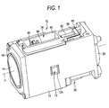
- Fig. 1 is a perspective view showing a lens apparatus to which applied is an actuator according to an exemplary embodiment of the present invention.
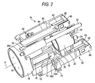
- Fig. 2 is a perspective view showing an interior construction of the lens apparatus in Fig. 1.
- Fig. 3 is a perspective view of the lens apparatus as viewed in the different direction from Fig. 2.
- Fig. 4 is a perspective view showing a construction of an actuator.
- Fig. 5 is a sectional view showing a connection between the drive shaft and the coupling piece.
- Fig. 6A and 6B are figures showing examples of a voltage drive pulse to be applied to a piezoelectric element.
- Fig. 7 is a sectional view showing a connection structured different from Fig. 5.
- Fig. 8 is a sectional view showing a connection of an actuator in a comparative example.
- With reference to the accompanying drawings, description is now made in detail on an exemplary embodiment of an actuator according to the present invention.
- Fig. 1 is a perspective view showing a
lens apparatus 10 to which is applied an actuator according to an aspect of the invention. Figs. 2 and 3 are perspective views showing an internal arrangement of the same. - As shown in Fig. 1, the
lens apparatus 10 has abody 12 formed nearly rectangular in form. Thebody 12 has therein zoom lenses (groups) 14, 16 that are shown in Figs. 2 and 3. Of the zoom lenses (groups) 14, 16, one is provided as a variable power lens while the other is as a correction lens. The zoom lenses (groups) 14, 16 are respectively held insupport frames support frames guide rods guide rods body 12 and parallel with the optical axis P, thus being fixed on thebody 12. - The
support frame 18 has aguide 26 having a bore in which theguide rod 22 is inserted and a U-groove 28A with which theguide rod 24 is engaged. Due to this, theguide frame 18 is to be guided over the twoguide rods support frame 20 for thezoom lens 16 has aguide 30 having an insert bore (not shown) in which theguide rod 24 is inserted and an engager 32 having aU-groove 32A with which theguide rod 22 is engaged. Due to this, theguide frame 20 is to be guided over the twoguide rods - The zoom lenses (groups) 14, 16 are driven in the direction of the optical-axis P respectively by the
actuators actuators body 12. Specifically, theactuator 34 for the zoom lens (group) 14 is arranged on the top surface of the Fig. 1body 12 while theactuator 36 for the zoom lens (group) 16 is on the bottom surface of thebody 12. The explanation in the following is on theactuator 34, which is the case with theactuator 36. - Incidentally,
reference numerals support frame position detector 72, or reflective photo-interrupter, is arranged opposite to a plate-like reflector unit 78 integrally formed with the support frame 18 (or the support frame 20) so that it can be fixedly received in anaperture 12A of the body 12 (see Fig. 1). In thereflector unit 78, a plurality of reflectors (not shown) are arranged at a constant interval in the drive direction. Consequently, by receiving the reflection of the light emitted from theposition detector 72 to thereflector unit 78 and detecting a change in the amount of that light, it is possible to detect a moving amount of the reflector unit 78 (i.e. support frame 18, 20). Meanwhile, theposition detector 74 has alight emitter 74A and alight receiver 74B. Between thelight emitter 74A and thelight receiver 74B, a plate-like shade 76 is to be inserted which is integrally formed with the support frame 18 (or support frame 20). Consequently, due to an insertion of theshade 76 between thelight emitter 74A and thelight receiver 74B, thelight receiver 74B is to receive a changing amount of light. This makes it possible to detect a fact the shade 76 (i.e.support frame 18, 20) has moved to a predetermined point. In this manner, theposition detector 74 detects a reference position of thesupport frame position detector 72 detects a moving amount of thesupport frame support frame actuators position detector - Fig. 4 is a perspective view showing an arrangement of the
actuator 34. As shown in the figure, theactuator 34 is mainly constructed with a fixedframe 40, a piezoelectric element (corresponding to an electro-mechanical conversion element) 42, a drive shaft (corresponding to a driving frictional member) 44, a coupling piece (corresponding to a driven member) 46 and afixture 48. The fixedframe 40 is secured to thebody 12 for the Fig. 1lens apparatus 10. - The
piezoelectric element 42 is formed laminated in the direction of the optical-axis P (hereinafter referred to as a drive direction), thus being structured to deform (expand and contract) in the drive direction due to the application of voltage. Accordingly, by applying a voltage to thepiezoelectric element 42, its lengthwise end faces 42A, 42B make a displacement in the drive direction. - Of the end faces 42A, 42B of the
piezoelectric element 42, oneend face 42A is secured to a base of thedrive shaft 44 while theother end face 42B is fixed, by bonding, to aweight member 58 formed of non-rigid material. - The
weight member 58 is to impart a load to theend face 42B, thereby preventing the displacement of theend face 42B greater than that of theend face 42A. Accordingly, theweight member 58 is preferably greater in weight than thedrive shaft 44. Theweight member 58 uses a material smaller in Young's modulus than thepiezoelectric element 42 and driveshaft 44, e.g. structured of a material having 300 MPa or smaller. For example, theweight member 58 is formed of a urethane rubber, a urethane resin or the like, and made by mixing such a rubber or resin with a metal powder, such as of tungsten, in order to raise the specific gravity. The specific gravity of theweight member 58 is preferably as high as possible for the sake of size reduction, e.g. set at 8 - 12 or the around. - The
weight member 58 is bonded to thefixture 48, at a side opposite to thepiezoelectric element 42. Thefixture 48 is formed by bending a metal sheet into a squared-U form, thus being formed withapertures 48B in its bent regions at both ends. Thefixture 48 is attached to the fixedframe 40 by being fitted at theapertures 48B over theprojections 40B of the fixedframe 40. Due to this, thepiezoelectric element 42 is held in the fixedframe 40 through theweight member 58 andfixture 48. - The
piezoelectric element 42 is held displaceable at itsend face 42B in the drive direction. Namely, theend face 42B of thepiezoelectric element 42 is allowed to displace through an expansion and contraction of thenon-rigid weight member 58 or a deflection of thefixture 48. - Meanwhile, the
drive shaft 44, secured to theend face 42A of thepiezoelectric element 42, is formed in a circular-cylinder form and arranged to have an axis thereof aligned in the drive direction. Thedrive shaft 44 is inserted in and guided by twobores frame 40, thus being supported slidable in the axial direction. Thedrive shaft 44 uses, as a material, graphite crystal complex that graphite crystal is firmly combined together, e.g. carbon graphite. - As shown in Fig. 4, the
drive shaft 44 is engaged with thecoupling piece 46. Thecoupling piece 46 is connected to thesupport frame 18 of thezoom lens 14 so that it can be supported to slide together with thesupport frame 18 in the direction of the optical-axis P (in the drive direction). Meanwhile, thecoupling piece 46 is formed in a rectangular-parallelepiped form to haveprojections - Fig. 5 is a sectional view of a connection between the
coupling piece 46 and thedrive shaft 44. As shown in the figure, apressure spring 56 is attached on thecoupling piece 46. Thepressure spring 56 is formed by bending a metal sheet well in slidability, e.g. stainless steel, and attached on thecoupling piece 46 by engaging theclaw 56A in the lower portion of thecoupling piece 46. Meanwhile, thepressure spring 56 has afirst slide member 56B arranged above thedrive shaft 44 and asecond slide member 56C arranged below thedrive shaft 44. Thefirst slide member 56B is formed in an inverted-V form while thesecond slide member 56C is in a V-form so that thedrive shaft 44 can be clamped by the first andsecond slide members coupling piece 46 and thedrive shaft 44 through the first andsecond slide members pressure spring 56. Incidentally, the frictional force between thecoupling piece 46 and thedrive shaft 44 is established greater than a drive force caused upon applying a drive pulse with a moderate voltage change to thepiezoelectric element 42 but smaller than a drive force caused upon applying a drive pulse with an abrupt voltage change to thepiezoelectric element 42. In such a case, the frictional force (slide resistance) is preferably of from 10 gf to 30 gf, more preferably from 15 gf to 25 gf. - A drive pulse voltage, shown in Figs. 6A and 6B, is applied to the
piezoelectric element 42. Fig. 6A depicts a drive pulse for driving the Fig. 4coupling piece 46 toward the left while Fig. 6B a drive pulse for driving the Fig. 4coupling piece 46 toward the right. - In the case of Fig. 6A, applied to the
piezoelectric pulse 42 is a drive pulse nearly in a saw-tooth form that rises moderately at time from α1 to α2 and abruptly falls at time α3. Accordingly, thepiezoelectric element 42 expands moderately in time of α1 to α2. In this duration, because thedrive shaft 44 moves at a moderate rate, thecoupling piece 46 moves together with thedrive shaft 44. This can move the Fig. 4coupling piece 46 toward the left. At time α3, thepiezoelectric element 42 contracts abruptly, and accordingly thedrive shaft 44 moves toward the right. In this duration, because of an abrupt movement of thedrive shaft 44, only thedrive shaft 44 moves while thecoupling piece 46 stays in the position due to its inertia. Accordingly, by repetitively applying the saw-tooth drive pulse shown in Fig. 6A, the Fig. 4coupling piece 46 repeats the leftward movement and rest, thus being moved toward the left. - In the case of Fig. 6B, applied to the
piezoelectric pulse 42 is a drive pulse nearly in a saw-tooth form that falls moderately at time from β1 to β2 and abruptly rises at time β3. Accordingly, thepiezoelectric element 42 contracts moderately in time of β1 to β2. In this duration, because thedrive shaft 44 displaces moderately, thecoupling piece 46 moves together with thedrive shaft 44. This can move the Fig. 4coupling piece 46 toward the right. At time β3, thepiezoelectric element 42 expands abruptly, and accordingly thedrive shaft 44 moves toward the left. In this duration, because of an abrupt movement of thedrive shaft 44, only thedrive shaft 44 moves while thecoupling piece 46 stays in the position due to its inertia. Accordingly, by repetitively applying the saw-tooth drive pulse shown in Fig. 6B, the Fig. 4coupling piece 46 repeats the rightward movement and rest, thus being moved toward the right. - The operation of the
actuator 34 thus constructed is now explained. - Fig. 8 is an actuator as a comparative example, showing a section taken of its
drive shaft 44 andcoupling piece 46. In the comparative-example actuator shown in the figure, there are provided first andsecond slide members pressure spring 56. Namely, thefirst slide member 52 is provided above thedrive shaft 44 while thesecond drive member 54 is below the same wherein the first andsecond slide members first slide member 52 downward by means of thepressure spring 56. The actuator thus structured involves a problem that, when thecoupling piece 46 is moved along thedrive shaft 44, the first andsecond slide members second slide members pressure spring 56, there is a problem of poor assembling efficiency. - On the contrary, in the
actuator 34 shown in Fig. 5 embodiment, thepressure spring 56 has the first andsecond slide members pressure spring 56 serves as both biasing means and a slide member. This eliminates the need of separately providing a slide member, thus making it possible to reduce the number of components and improve the efficiency of assembling, thus reducing the cost. - Meanwhile, the embodiment provided the first and
second slide members pressure spring 56, whichpressure spring 56 is fixed on thecoupling piece 46. There is no fear that the first andsecond slide members drive shaft 44 and thecoupling piece 46 can be kept nearly constant, thus enabling a drive control with stability. Particularly, the embodiment clamped thedrive shaft 44 by means of the first andsecond drive shaft - Incidentally, the embodiment provided the first and
second slide members pressure spring 56. Instead, only one of those may be provided. For example, Fig. 7 shows a case that afirst slide member 56B only is provided in thepressure spring 56 wherein asecond slide member 54 is provided as a separate member. Where thefirst slide member 56B is provided in thepressure spring 56 in this manner, the number of components can be reduced to improve the assembling efficiency. Furthermore, drive control can be effected with stability while suppressing against the change in the frictional force. Likewise, asecond slide member 56C only may be provided in thepressure spring 56, to provide a first slide member as a separate member. - Meanwhile, the embodiment formed the first and
second slide members pressure spring 56 in an inverted-V or V form. However, this is not limitative but those may be formed in such an arcuate form as placed in plane-contact with thedrive shaft 44. - Incidentally, the material of the
weight member 58 is not limited to the non-rigid material mentioned before but may use a rigid material. However, the use of a non-rigid material is preferred in respect of the following point. Namely, the use of aweight member 58 of a non-rigid material lowers the resonant frequency of a system formed by thepiezoelectric element 42, the drivingfrictional member 44 and theweight member 58. The lowering in the resonant frequency reduces the effect due to the variation in the structure of thepiezoelectric element 42, the drivingfrictional member 44 and theweight member 58, thus obtaining a stable drive force. Meanwhile, by lowering the resonant frequency f0, drive frequency f can be easily set within an anti-vibrating region of f ≥ 21/2· f0 wherein the effect of resonance is reduced to provide a stable drive force. This can positively convey, to the driven member, the drive force caused by an expansion and contraction of thepiezoelectric element 42, thus correctly moving the driven member in the direction of expansion and contraction of thepiezoelectric element 42. Furthermore, because the resonant frequency f0 is decreased to reduce the effect of resonance, actuator-support position and method can be desirably selected. For example, the actuator can be held on theend face 42A or side surface of thepiezoelectric element 42 or on the side surface or end face of thedrive shaft 44. - It will be apparent to those skilled in the art that various modifications and variations can be made to the described embodiments of the invention without departing from the spirit or scope of the invention. Thus, it is intended that the invention cover all modifications and variations of this invention consistent with the scope of the appended claims and their equivalents.
- The present application claims foreign priority based on
Japanese Patent Application No. 2005-234643
Claims (4)
- An actuator comprising:an electro-mechanical conversion element;a driving frictional member attached at one end of the electro-mechanical conversion element with respect to a direction of expansion and contraction of the electro-mechanical conversion element;a driven member frictionally engaged with the driving frictional member; anda biasing unit attached to the driven member and biasing the driven member and the driving frictional member in a direction of engagement thereof, wherein the biasing unit comprises at least one slide member sliding over the driving frictional member, and the driving frictional member and the driven member is frictionally engaged with each other through the at least one slide member.
- The actuator according to claim 1, wherein the at least one slide member comprises two slide members sandwiching and holding the driving frictional member therebetween.
- The actuator according to claim 1, wherein the driven member is attached with a support frame of a zoom lens.
- A lens drive apparatus comprising an actuator according to claim 1.
Applications Claiming Priority (1)
| Application Number | Priority Date | Filing Date | Title |
|---|---|---|---|
| JP2005234643A JP2007049878A (en) | 2005-08-12 | 2005-08-12 | Actuator |
Publications (2)
| Publication Number | Publication Date |
|---|---|
| EP1752806A1 true EP1752806A1 (en) | 2007-02-14 |
| EP1752806B1 EP1752806B1 (en) | 2009-02-11 |
Family
ID=37277268
Family Applications (1)
| Application Number | Title | Priority Date | Filing Date |
|---|---|---|---|
| EP06016738A Not-in-force EP1752806B1 (en) | 2005-08-12 | 2006-08-10 | Actuator and lens drive apparatus |
Country Status (6)
| Country | Link |
|---|---|
| US (1) | US20070035858A1 (en) |
| EP (1) | EP1752806B1 (en) |
| JP (1) | JP2007049878A (en) |
| CN (1) | CN1913325A (en) |
| AT (1) | ATE422678T1 (en) |
| DE (1) | DE602006005112D1 (en) |
Cited By (2)
| Publication number | Priority date | Publication date | Assignee | Title |
|---|---|---|---|---|
| EP1983587A3 (en) * | 2007-04-17 | 2009-09-30 | Mitsumi Electric Co., Ltd. | Driving device capable of obtaining a stable frequency characteristic |
| CN111684353A (en) * | 2018-01-30 | 2020-09-18 | Lg伊诺特有限公司 | camera module |
Families Citing this family (12)
| Publication number | Priority date | Publication date | Assignee | Title |
|---|---|---|---|---|
| JP4936934B2 (en) * | 2007-03-02 | 2012-05-23 | 株式会社日立ハイテクノロジーズ | Stage mechanism, electron microscope equipped with the same, and stage mechanism positioning control method |
| JP5267904B2 (en) * | 2007-09-12 | 2013-08-21 | コニカミノルタ株式会社 | Manufacturing method of engaging member |
| JP4972788B2 (en) * | 2007-09-12 | 2012-07-11 | コニカミノルタアドバンストレイヤー株式会社 | Engaging member, lens driving mechanism, and imaging device |
| WO2009066444A1 (en) * | 2007-11-19 | 2009-05-28 | Nec Tokin Corporation | Lens module |
| JP2011043526A (en) * | 2007-12-20 | 2011-03-03 | Nec Tokin Corp | Lens module |
| JP5275879B2 (en) * | 2009-04-01 | 2013-08-28 | オリンパス株式会社 | Endoscope device |
| JP5569535B2 (en) * | 2009-11-04 | 2014-08-13 | コニカミノルタ株式会社 | Drive mechanism and image pickup apparatus using the same |
| KR101782999B1 (en) * | 2011-06-21 | 2017-09-29 | 삼성전자주식회사 | Image stabilizing apparatus |
| JP2013250297A (en) * | 2012-05-30 | 2013-12-12 | Konica Minolta Inc | Driving mechanism and lens moving mechanism |
| DE102013201604B4 (en) * | 2013-01-31 | 2014-10-23 | Picofine GmbH | Tilting device and method for tilting |
| JP5523614B2 (en) * | 2013-05-16 | 2014-06-18 | オリンパス株式会社 | Endoscope device |
| CN114942505B (en) * | 2021-02-08 | 2023-10-27 | 宁波舜宇光电信息有限公司 | Variable-focus camera module |
Citations (3)
| Publication number | Priority date | Publication date | Assignee | Title |
|---|---|---|---|---|
| US20030168940A1 (en) * | 2002-01-10 | 2003-09-11 | Kazuhito Kurita | Drive unit |
| US20040012304A1 (en) * | 2001-01-22 | 2004-01-22 | Ryuichi Yoshida | Drive mechanism employing electromechanical transducer and method for controlling the drive mechanism |
| EP1708287A2 (en) * | 2005-03-31 | 2006-10-04 | Fujinon Corporation | Driving mechanism |
Family Cites Families (2)
| Publication number | Priority date | Publication date | Assignee | Title |
|---|---|---|---|---|
| US5589723A (en) * | 1994-03-29 | 1996-12-31 | Minolta Co., Ltd. | Driving apparatus using transducer |
| JP4120278B2 (en) * | 2002-06-04 | 2008-07-16 | コニカミノルタホールディングス株式会社 | Linear actuator |
-
2005
- 2005-08-12 JP JP2005234643A patent/JP2007049878A/en not_active Withdrawn
-
2006
- 2006-08-10 US US11/501,850 patent/US20070035858A1/en not_active Abandoned
- 2006-08-10 CN CNA2006101087417A patent/CN1913325A/en active Pending
- 2006-08-10 DE DE602006005112T patent/DE602006005112D1/en not_active Expired - Fee Related
- 2006-08-10 EP EP06016738A patent/EP1752806B1/en not_active Not-in-force
- 2006-08-10 AT AT06016738T patent/ATE422678T1/en not_active IP Right Cessation
Patent Citations (3)
| Publication number | Priority date | Publication date | Assignee | Title |
|---|---|---|---|---|
| US20040012304A1 (en) * | 2001-01-22 | 2004-01-22 | Ryuichi Yoshida | Drive mechanism employing electromechanical transducer and method for controlling the drive mechanism |
| US20030168940A1 (en) * | 2002-01-10 | 2003-09-11 | Kazuhito Kurita | Drive unit |
| EP1708287A2 (en) * | 2005-03-31 | 2006-10-04 | Fujinon Corporation | Driving mechanism |
Cited By (3)
| Publication number | Priority date | Publication date | Assignee | Title |
|---|---|---|---|---|
| EP1983587A3 (en) * | 2007-04-17 | 2009-09-30 | Mitsumi Electric Co., Ltd. | Driving device capable of obtaining a stable frequency characteristic |
| CN111684353A (en) * | 2018-01-30 | 2020-09-18 | Lg伊诺特有限公司 | camera module |
| US12591106B2 (en) | 2018-01-30 | 2026-03-31 | Lg Innotek Co., Ltd. | Camera module |
Also Published As
| Publication number | Publication date |
|---|---|
| CN1913325A (en) | 2007-02-14 |
| DE602006005112D1 (en) | 2009-03-26 |
| US20070035858A1 (en) | 2007-02-15 |
| JP2007049878A (en) | 2007-02-22 |
| ATE422678T1 (en) | 2009-02-15 |
| EP1752806B1 (en) | 2009-02-11 |
Similar Documents
| Publication | Publication Date | Title |
|---|---|---|
| EP1752806B1 (en) | Actuator and lens drive apparatus | |
| US8040623B2 (en) | Compact auto focus lens module with piezoelectric actuator | |
| CN115016092B (en) | Driving device for camera | |
| KR100777630B1 (en) | Driving machanism | |
| EP1753042B1 (en) | Actuator | |
| EP1753041A2 (en) | Actuator | |
| KR100777634B1 (en) | Driving mechanism | |
| JP2007053826A (en) | Actuator | |
| US7433138B2 (en) | Actuator | |
| US7403342B2 (en) | Lens device | |
| EP1753040A1 (en) | Actuator and lens drive apparatus | |
| US8520329B2 (en) | Piezoelectric actuator, lens barrel and optical device | |
| US7365914B2 (en) | Actuator | |
| EP1752807B1 (en) | Actuator and lens drive apparatus | |
| US20070035205A1 (en) | Actuator | |
| KR20110001232U (en) | Compact auto focus lens module with piezoelectric actuator |
Legal Events
| Date | Code | Title | Description |
|---|---|---|---|
| PUAI | Public reference made under article 153(3) epc to a published international application that has entered the european phase |
Free format text: ORIGINAL CODE: 0009012 |
|
| 17P | Request for examination filed |
Effective date: 20060810 |
|
| AK | Designated contracting states |
Kind code of ref document: A1 Designated state(s): AT BE BG CH CY CZ DE DK EE ES FI FR GB GR HU IE IS IT LI LT LU LV MC NL PL PT RO SE SI SK TR |
|
| AX | Request for extension of the european patent |
Extension state: AL BA HR MK YU |
|
| AKX | Designation fees paid |
Designated state(s): AT BE BG CH CY CZ DE DK EE ES FI FR GB GR HU IE IS IT LI LT LU LV MC NL PL PT RO SE SI SK TR |
|
| 17Q | First examination report despatched |
Effective date: 20071123 |
|
| GRAP | Despatch of communication of intention to grant a patent |
Free format text: ORIGINAL CODE: EPIDOSNIGR1 |
|
| GRAS | Grant fee paid |
Free format text: ORIGINAL CODE: EPIDOSNIGR3 |
|
| GRAA | (expected) grant |
Free format text: ORIGINAL CODE: 0009210 |
|
| AK | Designated contracting states |
Kind code of ref document: B1 Designated state(s): AT BE BG CH CY CZ DE DK EE ES FI FR GB GR HU IE IS IT LI LT LU LV MC NL PL PT RO SE SI SK TR |
|
| REG | Reference to a national code |
Ref country code: GB Ref legal event code: FG4D |
|
| REG | Reference to a national code |
Ref country code: CH Ref legal event code: EP |
|
| REG | Reference to a national code |
Ref country code: IE Ref legal event code: FG4D |
|
| REF | Corresponds to: |
Ref document number: 602006005112 Country of ref document: DE Date of ref document: 20090326 Kind code of ref document: P |
|
| PG25 | Lapsed in a contracting state [announced via postgrant information from national office to epo] |
Ref country code: SI Free format text: LAPSE BECAUSE OF FAILURE TO SUBMIT A TRANSLATION OF THE DESCRIPTION OR TO PAY THE FEE WITHIN THE PRESCRIBED TIME-LIMIT Effective date: 20090211 Ref country code: FI Free format text: LAPSE BECAUSE OF FAILURE TO SUBMIT A TRANSLATION OF THE DESCRIPTION OR TO PAY THE FEE WITHIN THE PRESCRIBED TIME-LIMIT Effective date: 20090211 Ref country code: ES Free format text: LAPSE BECAUSE OF FAILURE TO SUBMIT A TRANSLATION OF THE DESCRIPTION OR TO PAY THE FEE WITHIN THE PRESCRIBED TIME-LIMIT Effective date: 20090522 Ref country code: LT Free format text: LAPSE BECAUSE OF FAILURE TO SUBMIT A TRANSLATION OF THE DESCRIPTION OR TO PAY THE FEE WITHIN THE PRESCRIBED TIME-LIMIT Effective date: 20090211 Ref country code: NL Free format text: LAPSE BECAUSE OF FAILURE TO SUBMIT A TRANSLATION OF THE DESCRIPTION OR TO PAY THE FEE WITHIN THE PRESCRIBED TIME-LIMIT Effective date: 20090211 |
|
| NLV1 | Nl: lapsed or annulled due to failure to fulfill the requirements of art. 29p and 29m of the patents act | ||
| PG25 | Lapsed in a contracting state [announced via postgrant information from national office to epo] |
Ref country code: IS Free format text: LAPSE BECAUSE OF FAILURE TO SUBMIT A TRANSLATION OF THE DESCRIPTION OR TO PAY THE FEE WITHIN THE PRESCRIBED TIME-LIMIT Effective date: 20090611 Ref country code: SE Free format text: LAPSE BECAUSE OF FAILURE TO SUBMIT A TRANSLATION OF THE DESCRIPTION OR TO PAY THE FEE WITHIN THE PRESCRIBED TIME-LIMIT Effective date: 20090511 Ref country code: LV Free format text: LAPSE BECAUSE OF FAILURE TO SUBMIT A TRANSLATION OF THE DESCRIPTION OR TO PAY THE FEE WITHIN THE PRESCRIBED TIME-LIMIT Effective date: 20090211 Ref country code: PL Free format text: LAPSE BECAUSE OF FAILURE TO SUBMIT A TRANSLATION OF THE DESCRIPTION OR TO PAY THE FEE WITHIN THE PRESCRIBED TIME-LIMIT Effective date: 20090211 Ref country code: AT Free format text: LAPSE BECAUSE OF FAILURE TO SUBMIT A TRANSLATION OF THE DESCRIPTION OR TO PAY THE FEE WITHIN THE PRESCRIBED TIME-LIMIT Effective date: 20090211 |
|
| PG25 | Lapsed in a contracting state [announced via postgrant information from national office to epo] |
Ref country code: BE Free format text: LAPSE BECAUSE OF FAILURE TO SUBMIT A TRANSLATION OF THE DESCRIPTION OR TO PAY THE FEE WITHIN THE PRESCRIBED TIME-LIMIT Effective date: 20090211 |
|
| PG25 | Lapsed in a contracting state [announced via postgrant information from national office to epo] |
Ref country code: DK Free format text: LAPSE BECAUSE OF FAILURE TO SUBMIT A TRANSLATION OF THE DESCRIPTION OR TO PAY THE FEE WITHIN THE PRESCRIBED TIME-LIMIT Effective date: 20090211 Ref country code: CZ Free format text: LAPSE BECAUSE OF FAILURE TO SUBMIT A TRANSLATION OF THE DESCRIPTION OR TO PAY THE FEE WITHIN THE PRESCRIBED TIME-LIMIT Effective date: 20090211 Ref country code: PT Free format text: LAPSE BECAUSE OF FAILURE TO SUBMIT A TRANSLATION OF THE DESCRIPTION OR TO PAY THE FEE WITHIN THE PRESCRIBED TIME-LIMIT Effective date: 20090713 Ref country code: EE Free format text: LAPSE BECAUSE OF FAILURE TO SUBMIT A TRANSLATION OF THE DESCRIPTION OR TO PAY THE FEE WITHIN THE PRESCRIBED TIME-LIMIT Effective date: 20090211 |
|
| PG25 | Lapsed in a contracting state [announced via postgrant information from national office to epo] |
Ref country code: RO Free format text: LAPSE BECAUSE OF FAILURE TO SUBMIT A TRANSLATION OF THE DESCRIPTION OR TO PAY THE FEE WITHIN THE PRESCRIBED TIME-LIMIT Effective date: 20090211 Ref country code: SK Free format text: LAPSE BECAUSE OF FAILURE TO SUBMIT A TRANSLATION OF THE DESCRIPTION OR TO PAY THE FEE WITHIN THE PRESCRIBED TIME-LIMIT Effective date: 20090211 |
|
| PLBE | No opposition filed within time limit |
Free format text: ORIGINAL CODE: 0009261 |
|
| STAA | Information on the status of an ep patent application or granted ep patent |
Free format text: STATUS: NO OPPOSITION FILED WITHIN TIME LIMIT |
|
| 26N | No opposition filed |
Effective date: 20091112 |
|
| PG25 | Lapsed in a contracting state [announced via postgrant information from national office to epo] |
Ref country code: BG Free format text: LAPSE BECAUSE OF FAILURE TO SUBMIT A TRANSLATION OF THE DESCRIPTION OR TO PAY THE FEE WITHIN THE PRESCRIBED TIME-LIMIT Effective date: 20090511 |
|
| PG25 | Lapsed in a contracting state [announced via postgrant information from national office to epo] |
Ref country code: MC Free format text: LAPSE BECAUSE OF NON-PAYMENT OF DUE FEES Effective date: 20090831 |
|
| REG | Reference to a national code |
Ref country code: FR Ref legal event code: ST Effective date: 20100430 |
|
| PG25 | Lapsed in a contracting state [announced via postgrant information from national office to epo] |
Ref country code: DE Free format text: LAPSE BECAUSE OF NON-PAYMENT OF DUE FEES Effective date: 20100302 Ref country code: IE Free format text: LAPSE BECAUSE OF NON-PAYMENT OF DUE FEES Effective date: 20090810 Ref country code: FR Free format text: LAPSE BECAUSE OF NON-PAYMENT OF DUE FEES Effective date: 20090831 |
|
| PG25 | Lapsed in a contracting state [announced via postgrant information from national office to epo] |
Ref country code: GR Free format text: LAPSE BECAUSE OF FAILURE TO SUBMIT A TRANSLATION OF THE DESCRIPTION OR TO PAY THE FEE WITHIN THE PRESCRIBED TIME-LIMIT Effective date: 20090512 |
|
| PG25 | Lapsed in a contracting state [announced via postgrant information from national office to epo] |
Ref country code: IT Free format text: LAPSE BECAUSE OF FAILURE TO SUBMIT A TRANSLATION OF THE DESCRIPTION OR TO PAY THE FEE WITHIN THE PRESCRIBED TIME-LIMIT Effective date: 20090211 |
|
| REG | Reference to a national code |
Ref country code: CH Ref legal event code: PL |
|
| GBPC | Gb: european patent ceased through non-payment of renewal fee |
Effective date: 20100810 |
|
| PG25 | Lapsed in a contracting state [announced via postgrant information from national office to epo] |
Ref country code: LU Free format text: LAPSE BECAUSE OF NON-PAYMENT OF DUE FEES Effective date: 20090810 Ref country code: LI Free format text: LAPSE BECAUSE OF NON-PAYMENT OF DUE FEES Effective date: 20100831 Ref country code: CH Free format text: LAPSE BECAUSE OF NON-PAYMENT OF DUE FEES Effective date: 20100831 |
|
| PG25 | Lapsed in a contracting state [announced via postgrant information from national office to epo] |
Ref country code: HU Free format text: LAPSE BECAUSE OF FAILURE TO SUBMIT A TRANSLATION OF THE DESCRIPTION OR TO PAY THE FEE WITHIN THE PRESCRIBED TIME-LIMIT Effective date: 20090812 |
|
| PG25 | Lapsed in a contracting state [announced via postgrant information from national office to epo] |
Ref country code: GB Free format text: LAPSE BECAUSE OF NON-PAYMENT OF DUE FEES Effective date: 20100810 Ref country code: TR Free format text: LAPSE BECAUSE OF FAILURE TO SUBMIT A TRANSLATION OF THE DESCRIPTION OR TO PAY THE FEE WITHIN THE PRESCRIBED TIME-LIMIT Effective date: 20090211 |
|
| PG25 | Lapsed in a contracting state [announced via postgrant information from national office to epo] |
Ref country code: CY Free format text: LAPSE BECAUSE OF FAILURE TO SUBMIT A TRANSLATION OF THE DESCRIPTION OR TO PAY THE FEE WITHIN THE PRESCRIBED TIME-LIMIT Effective date: 20090211 |