EP1752686A1 - Ball screw - Google Patents
Ball screw Download PDFInfo
- Publication number
- EP1752686A1 EP1752686A1 EP05737206A EP05737206A EP1752686A1 EP 1752686 A1 EP1752686 A1 EP 1752686A1 EP 05737206 A EP05737206 A EP 05737206A EP 05737206 A EP05737206 A EP 05737206A EP 1752686 A1 EP1752686 A1 EP 1752686A1
- Authority
- EP
- European Patent Office
- Prior art keywords
- ball
- screw
- groove
- balls
- screw shaft
- Prior art date
- Legal status (The legal status is an assumption and is not a legal conclusion. Google has not performed a legal analysis and makes no representation as to the accuracy of the status listed.)
- Withdrawn
Links
Images

Classifications
-
- F—MECHANICAL ENGINEERING; LIGHTING; HEATING; WEAPONS; BLASTING
- F16—ENGINEERING ELEMENTS AND UNITS; GENERAL MEASURES FOR PRODUCING AND MAINTAINING EFFECTIVE FUNCTIONING OF MACHINES OR INSTALLATIONS; THERMAL INSULATION IN GENERAL
- F16H—GEARING
- F16H25/00—Gearings comprising primarily only cams, cam-followers and screw-and-nut mechanisms
- F16H25/18—Gearings comprising primarily only cams, cam-followers and screw-and-nut mechanisms for conveying or interconverting oscillating or reciprocating motions
- F16H25/20—Screw mechanisms
- F16H25/22—Screw mechanisms with balls, rollers, or similar members between the co-operating parts; Elements essential to the use of such members
- F16H25/2204—Screw mechanisms with balls, rollers, or similar members between the co-operating parts; Elements essential to the use of such members with balls
- F16H25/2214—Screw mechanisms with balls, rollers, or similar members between the co-operating parts; Elements essential to the use of such members with balls with elements for guiding the circulating balls
- F16H25/2228—Screw mechanisms with balls, rollers, or similar members between the co-operating parts; Elements essential to the use of such members with balls with elements for guiding the circulating balls the device for circulation forming a part of the screw member
-
- Y—GENERAL TAGGING OF NEW TECHNOLOGICAL DEVELOPMENTS; GENERAL TAGGING OF CROSS-SECTIONAL TECHNOLOGIES SPANNING OVER SEVERAL SECTIONS OF THE IPC; TECHNICAL SUBJECTS COVERED BY FORMER USPC CROSS-REFERENCE ART COLLECTIONS [XRACs] AND DIGESTS
- Y10—TECHNICAL SUBJECTS COVERED BY FORMER USPC
- Y10T—TECHNICAL SUBJECTS COVERED BY FORMER US CLASSIFICATION
- Y10T74/00—Machine element or mechanism
- Y10T74/19—Gearing
- Y10T74/19642—Directly cooperating gears
- Y10T74/19698—Spiral
- Y10T74/19702—Screw and nut
- Y10T74/19744—Rolling element engaging thread
- Y10T74/19749—Recirculating rolling elements
- Y10T74/19777—Interconnected or cooperating rollers or roller structure
Definitions
- the present invention relates to a ball screw in which a plurality of balls are caused to run in a circulating manner between a screw shaft and a nut and which is used to effect conversion between a linear motion and a rotational motion.
- a ball circulation method for a ball screw is classified into a method in which a return tube is provided outside the nut, and a method in which a circulation component called a bridge is provided in a part of the screw groove of the nut.
- the former method is adopted when balls corresponding to a plurality of screw grooves are to be returned, and the latter method is adopted when balls corresponding to one row of screw groove are to be returned.
- JP 2003-148573 A discloses a construction in which the width of a V-pulley is controlled by a ball screw actuator whose nut is equipped with a bridge.
- the present invention achieves the object by arranging permanent magnets at an inlet and an outlet, respectively, of a ball circulating portion in a ball screw in which the ball circulating portion is provided on a screw shaft side.
- a ball screw includes: a screw shaft having a screw groove in an outer peripheral surface thereof; a nut having a screw groove in an inner peripheral surface thereof; and a plurality of balls provided between the screw groove of the screw shaft and the screw groove of the nut, in which the screw groove of the screw shaft forms a closed loop composed of a ball rolling groove corresponding to approximately one turn and a circulating portion connecting a start point and a terminal point of the ball rolling groove, in which the circulating portion is composed of an inlet portion gradually deepening from the ball rolling groove, a portion deep enough to allow the balls to pass through a bore of the nut, and an outlet portion gradually lessened in depth toward the ball rolling groove, and in which guide means for attracting the balls to the groove bottom are provided at the inlet portion and the outlet portion of the circulating portion.
- the guide means may attract a ball with a force larger than a force applied to the ball from contiguous balls before and behind and pushing the ball away from the groove bottom.
- the guide means may be formed by permanent magnets embedded in the screw shaft.
- the guide means may be formed by partially magnetizing the circulating portion of the screw shaft.
- the ball rolling groove and the circulating portion are continuous with each other and involves no step, so it is possible to realize a smooth ball circulating motion. Further, since the bridge can be abolished, it is possible to achieve a reduction in the thickness and weight of the nut, thereby achieving a reduction in cost.
- Fig. 1 shows a screw shaft circulation type ball screw 10, in which the ball circulating portion is provided on the screw shaft side.
- the ball screw 10 is composed of a screw shaft 12, a nut 18, and balls 22.
- the screw shaft 12 has a ball rolling groove 14 in the outer periphery thereof, and the nut 18 has a ball rolling groove 20 in the inner periphery thereof, with the balls 22 running in a circulating manner along both the ball rolling grooves 14, 20.
- the ball screw 10 is used as a mechanism for converting a linear motion to a rotational motion or, conversely, a rotational motion to a linear motion between the screw shaft 12 and the nut 18.
- a case is shown in which the screw shaft 12 is provided with the ball rolling groove 14 corresponding to one turn of screw groove.
- the machining of the screw groove 12 is performed by a ball end mill, and while smoothly changing the direction and depth of the screw groove by the same end mill, there is machined a circulating portion 16 connecting the ends of the ball rolling groove 14.
- the circulating portion 16 is machined to be deep enough to allow the balls 22 to pass through the bore of the nut 18.
- This is effected by a permanent magnet 24.
- the permanent magnet 24 is embedded at the inlet of the circulating portion 16 where the groove starts to deepen.
- FIGs. 4A through 4D are schematic sectional views taken along the circulating portion 16 of the screw shaft 12.
- Figs. 5A through 5D are schematic diagrams for comparison, showing the behavior of the balls when there is no magnetic guide in the circulation portion.
- the movement of the balls when there is no permanent magnet 24, in other words, when there is no means for attracting the balls to the groove bottom will be discussed with reference to Figs. 5A through 5D. As shown in Fig.
- the permanent magnets 24 are embedded, one each, at the inlet and outlet of the circulating portion 16, it is also possible to arrange a plurality of permanent magnets in the circulating portion 16, that is, not only at the inlet and outlet of the circulating portion 16 but also therebetween. Instead of embedding the permanent magnets 24, the same effect can be obtained by using a permanent magnet material for the screw shaft 12 and locally magnetizing the circulating portion 16. Examples of the permanent magnet material include high carbon steel and bearing steel generally used for ball screws and bearings.
- the upper surfaces of the permanent magnets 24 are sunken from the groove bottom of the circulating portion 16, the force applied from the balls before and behind is also directed to the groove bottom, which, together with the attraction force of the permanent magnets 24, helps to achieve an enhancement in stability.
- a plurality of ball rolling grooves are provided.
- the circumferential positions of the circulating portions 16 are designed taking balance into consideration as in a case of the bridge type ball screw. For example, when the grooves are provided in two rows or three rows, it is desirable to arrange them at an interval of 180 degrees or 120 degrees, respectively.
- the ball screw device of the present invention is not restricted to the above-described embodiment. Various modifications are of course possible without departing from the gist of the present invention.
Landscapes
- Engineering & Computer Science (AREA)
- General Engineering & Computer Science (AREA)
- Mechanical Engineering (AREA)
- Transmission Devices (AREA)
Abstract
A ball screw has a screw shaft, a nut, and balls running in a circulating manner along a ball rolling groove of the screw shaft and a ball rolling groove of the nut. A circulating portion (16) for balls (22) is provided on a screw shaft (12) side, and permanent magnets (24) are arranged at an inlet and an outlet of the circulating portion (16).
Description
- The present invention relates to a ball screw in which a plurality of balls are caused to run in a circulating manner between a screw shaft and a nut and which is used to effect conversion between a linear motion and a rotational motion.
- A ball circulation method for a ball screw is classified into a method in which a return tube is provided outside the nut, and a method in which a circulation component called a bridge is provided in a part of the screw groove of the nut. The former method is adopted when balls corresponding to a plurality of screw grooves are to be returned, and the latter method is adopted when balls corresponding to one row of screw groove are to be returned.
- In a case in which the nut moves along a long screw shaft, a position of arrangement for the circulating portion is restricted to the nut side. However, in the case of a ball screw for use in pulley width adjustment in a metal belt type traction drive device, the stroke involved is small, so the ball screw functions as such regardless of whether the circulating portion is provided on the nut side or on the screw shaft side.
JP 2003-148573 A - In assembling the ball screw as disclosed in
JP 2003-148573 A - In this connection, there has been devised a system in which the circulation groove is cut in the screw shaft. By machining the screw groove (ball rolling groove) of the screw shaft and the circulating portion by a single end mill, it is possible to avoid generation of a step as involved in the case of the bridge type ball screw (see
JP 2003-97663 A JP 2003-166616 A - In either of the methods, however, it is impossible to positively cause the balls to sink in the circulating portion provided in the screw shaft, and jamming of the balls is involved.
- It is a main object of the present invention to realize a smooth ball circulating motion in a ball screw in which balls are caused to run in a circulating manner along a ball rolling groove of a screw shaft and a ball rolling groove of a nut.
- The present invention achieves the object by arranging permanent magnets at an inlet and an outlet, respectively, of a ball circulating portion in a ball screw in which the ball circulating portion is provided on a screw shaft side.
- According to an embodiment of the present invention, a ball screw includes: a screw shaft having a screw groove in an outer peripheral surface thereof; a nut having a screw groove in an inner peripheral surface thereof; and a plurality of balls provided between the screw groove of the screw shaft and the screw groove of the nut, in which the screw groove of the screw shaft forms a closed loop composed of a ball rolling groove corresponding to approximately one turn and a circulating portion connecting a start point and a terminal point of the ball rolling groove, in which the circulating portion is composed of an inlet portion gradually deepening from the ball rolling groove, a portion deep enough to allow the balls to pass through a bore of the nut, and an outlet portion gradually lessened in depth toward the ball rolling groove, and in which guide means for attracting the balls to the groove bottom are provided at the inlet portion and the outlet portion of the circulating portion.
- The guide means may attract a ball with a force larger than a force applied to the ball from contiguous balls before and behind and pushing the ball away from the groove bottom.
- The guide means may be formed by permanent magnets embedded in the screw shaft.
- The guide means may be formed by partially magnetizing the circulating portion of the screw shaft.
- According to the present invention, the ball rolling groove and the circulating portion are continuous with each other and involves no step, so it is possible to realize a smooth ball circulating motion. Further, since the bridge can be abolished, it is possible to achieve a reduction in the thickness and weight of the nut, thereby achieving a reduction in cost.
- These and other objects and features of the present invention will become more apparent from the following description given with reference to the accompanying drawings.
-
- [Fig. 1] A longitudinal sectional view of an embodiment of the present invention.
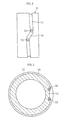
- [Fig. 2] A plan view of a screw shaft as seen in the direction of the arrow II of Fig. 1.
- [Fig. 3] A cross-sectional view of the screw shaft of Fig. 2.
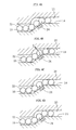
- [Fig. 4A] A schematic sectional view showing the behavior of balls at an inlet of a circulating portion.
- [Fig. 4B] A schematic sectional view showing the behavior of the balls at the inlet of the circulating portion.
- [Fig. 4C] A schematic sectional view showing the behavior of the balls at the inlet of the circulating portion.
- [Fig. 4D] A schematic sectional view showing the behavior of the balls at the inlet of the circulating portion.
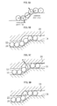
- [Fig. 5A] A vector diagram showing forces acting on balls.
- [Fig. 5B] A schematic sectional view of a circulating portion, showing the behavior of balls when there is no magnetic guide in the circulating portion.
- [Fig. 5C] A schematic sectional view of the circulating portion, showing the behavior of the balls when there is no magnetic guide in the circulating portion.
- [Fig. 5D] A schematic sectional view of the circulating portion, showing the behavior of the balls when there is no magnetic guide in the circulating portion.
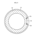
- [Fig. 6] A cross-sectional view similar to Fig. 3, showing another embodiment of the screw groove.
- Fig. 1 shows a screw shaft circulation
type ball screw 10, in which the ball circulating portion is provided on the screw shaft side. Theball screw 10 is composed of ascrew shaft 12, anut 18, andballs 22. Thescrew shaft 12 has aball rolling groove 14 in the outer periphery thereof, and thenut 18 has aball rolling groove 20 in the inner periphery thereof, with theballs 22 running in a circulating manner along both theball rolling grooves ball screw 10 is used as a mechanism for converting a linear motion to a rotational motion or, conversely, a rotational motion to a linear motion between thescrew shaft 12 and thenut 18. - As shown in Fig. 2 and Fig. 3, here, a case is shown in which the
screw shaft 12 is provided with theball rolling groove 14 corresponding to one turn of screw groove. The machining of thescrew groove 12 is performed by a ball end mill, and while smoothly changing the direction and depth of the screw groove by the same end mill, there is machined a circulatingportion 16 connecting the ends of theball rolling groove 14. The circulatingportion 16 is machined to be deep enough to allow theballs 22 to pass through the bore of thenut 18. Here, for smooth circulation, it is necessary to positively cause theballs 22 to move along the groove bottom of the circulatingportion 16 at the deepened inlet of the circulatingportion 16. This is effected by apermanent magnet 24. As shown in Fig. 2, thepermanent magnet 24 is embedded at the inlet of the circulatingportion 16 where the groove starts to deepen. - Here, the operation of the
permanent magnet 24 will be described in detail. Figs. 4A through 4D are schematic sectional views taken along the circulatingportion 16 of thescrew shaft 12. Figs. 5A through 5D are schematic diagrams for comparison, showing the behavior of the balls when there is no magnetic guide in the circulation portion. First, the movement of the balls when there is nopermanent magnet 24, in other words, when there is no means for attracting the balls to the groove bottom, will be discussed with reference to Figs. 5A through 5D. As shown in Fig. 5A, when a ball entering the circulatingportion 16 receives a force from the balls before and behind, an outwardly pressurizing force, that is, a force pushing the ball away from the groove bottom, is applied to that ball at the portion of the inlet having a convex curvature. Thus, as shown in Figs. 5B through 5D, before passing through the circulatingportion 16, the ball a is pressed against theball rolling groove 20 of thenut 18, and gets locked. - In contrast, in a case in which, as shown in Fig. 3, the
permanent magnet 24 is embedded in the portion of the circulatingportion 16 where its groove starts to deepen, the force with which thepermanent magnet 24 attracts the ball a to the groove bottom is stronger than the force F that the ball a receives from the balls before and behind. In other words, there is used a permanent magnet whose magnetic force is stronger than the force pushing the ball away from the groove bottom at the circulatingportion 16. Thus, the ball a moves along the groove bottom and can pass through the circulatingportion 16 without being locked. In this way, while passing thepermanent magnet 24, the ball is not separated from the groove bottom of the circulatingportion 16. In the meantime, the ball passes the convex portion. When, thereafter, it reaches a position where no attracting force is exerted from thepermanent magnet 24, there is generated no more force pushing the ball away from the groove bottom. - While in Fig. 3 the
permanent magnets 24 are embedded, one each, at the inlet and outlet of the circulatingportion 16, it is also possible to arrange a plurality of permanent magnets in the circulatingportion 16, that is, not only at the inlet and outlet of the circulatingportion 16 but also therebetween. Instead of embedding thepermanent magnets 24, the same effect can be obtained by using a permanent magnet material for thescrew shaft 12 and locally magnetizing the circulatingportion 16. Examples of the permanent magnet material include high carbon steel and bearing steel generally used for ball screws and bearings. - When, as shown in Fig. 6, the upper surfaces of the
permanent magnets 24 are sunken from the groove bottom of the circulatingportion 16, the force applied from the balls before and behind is also directed to the groove bottom, which, together with the attraction force of thepermanent magnets 24, helps to achieve an enhancement in stability. - When a single row of ball rolling groove does not provide the requisite load capacity, a plurality of ball rolling grooves (inclusive of the circulating portions 16) are provided. In this case, the circumferential positions of the circulating
portions 16 are designed taking balance into consideration as in a case of the bridge type ball screw. For example, when the grooves are provided in two rows or three rows, it is desirable to arrange them at an interval of 180 degrees or 120 degrees, respectively. - The ball screw device of the present invention is not restricted to the above-described embodiment. Various modifications are of course possible without departing from the gist of the present invention.
Claims (5)
- A ball screw, in which a ball circulating portion is provided on a screw shaft side, wherein permanent magnets are respectively arranged at an inlet and an outlet of the ball circulating portion.
- A ball screw, comprising: a screw shaft having a screw groove in an outer peripheral surface thereof; a nut having a screw groove in an inner peripheral surface thereof; and a plurality of balls provided between the screw groove of the screw shaft and the screw groove of the nut,
wherein the screw groove of the screw shaft forms a closed loop composed of a ball rolling groove corresponding to approximately one turn and a circulating portion connecting a start point and a terminal point of the ball rolling groove,
wherein the circulating portion is composed of an inlet portion gradually deepening from the ball rolling groove, a portion deep enough to allow the balls to pass through a bore of the nut, and an outlet portion gradually lessened in depth toward the ball rolling groove, and
wherein guide means for attracting the balls to the groove bottom are provided at the inlet portion and the outlet portion of the circulating portion. - A ball screw according to Claim 2, wherein the guide means attract a ball with a force larger than a force applied to the ball from contiguous balls before and behind and pushing the ball away from the groove bottom.
- A ball screw according to Claim 2, wherein the guide means are formed by permanent magnets embedded in the screw shaft.
- A ball screw according to Claim 2, wherein the guide means are formed by partially magnetizing the circulating portion of the screw shaft.
Applications Claiming Priority (2)
| Application Number | Priority Date | Filing Date | Title |
|---|---|---|---|
| JP2004163374A JP2005344782A (en) | 2004-06-01 | 2004-06-01 | Ball screw |
| PCT/JP2005/008363 WO2005119095A1 (en) | 2004-06-01 | 2005-05-06 | Ball screw |
Publications (2)
| Publication Number | Publication Date |
|---|---|
| EP1752686A1 true EP1752686A1 (en) | 2007-02-14 |
| EP1752686A4 EP1752686A4 (en) | 2010-08-04 |
Family
ID=35462984
Family Applications (1)
| Application Number | Title | Priority Date | Filing Date |
|---|---|---|---|
| EP05737206A Withdrawn EP1752686A4 (en) | 2004-06-01 | 2005-05-06 | Ball screw |
Country Status (4)
| Country | Link |
|---|---|
| US (1) | US20080229857A1 (en) |
| EP (1) | EP1752686A4 (en) |
| JP (1) | JP2005344782A (en) |
| WO (1) | WO2005119095A1 (en) |
Families Citing this family (5)
| Publication number | Priority date | Publication date | Assignee | Title |
|---|---|---|---|---|
| DE102006027942A1 (en) * | 2006-06-17 | 2007-12-20 | Schaeffler Kg | Ball screw, has spindle nut arranged on threaded spindle provided with recess for accommodating insert and return section formed as groove at inserts, and ball channel comprising load-section |
| JP2008238384A (en) * | 2007-03-29 | 2008-10-09 | Ntn Corp | Ball screw and screw groove machining method therefor |
| JP2011117513A (en) * | 2009-12-02 | 2011-06-16 | Ntn Corp | Electric actuator |
| JP6341419B2 (en) * | 2014-08-01 | 2018-06-13 | 株式会社ジェイテクト | Ball screw device |
| CN113441911B (en) * | 2021-06-23 | 2024-07-09 | 陕西德臻零部件科技有限公司 | Integrated processing method of internal circulation steering nut |
Family Cites Families (29)
| Publication number | Priority date | Publication date | Assignee | Title |
|---|---|---|---|---|
| US2924113A (en) * | 1960-02-09 | Orner | ||
| GB616979A (en) * | 1946-01-18 | 1949-01-31 | Alfred Paul Mill | Worm and nut mechanism |
| GB609854A (en) * | 1946-03-16 | 1948-10-07 | Rotax Ltd | Improvements relating to screw and nut mechanisms |
| US2450282A (en) * | 1946-07-18 | 1948-09-28 | Gen Motors Corp | Antifriction screw and nut actuator |
| US2895343A (en) * | 1954-10-01 | 1959-07-21 | Orner Harry | Ball-bearing screw and nut mechanism |
| US2882742A (en) * | 1955-10-14 | 1959-04-21 | Cleveland Pneumatic Ind Inc | Ball screw and nut construction |
| US3386307A (en) * | 1967-03-15 | 1968-06-04 | Avco Corp | Ball recirculating mechanism for ball screw and nut actuators |
| US3580098A (en) * | 1968-04-29 | 1971-05-25 | Rotax Ltd | Ball screw and nut mechanism |
| US3815435A (en) * | 1972-11-24 | 1974-06-11 | Warner Electric Brake & Clutch | Ball screw mechanism with improved ball guide |
| US4612817A (en) * | 1983-06-29 | 1986-09-23 | Neff Gewindespindeln Gmbh | Circulating ball worm drive |
| US4741221A (en) * | 1986-09-15 | 1988-05-03 | Mechanical Service Co. | Feed and rapid return means for machine tools |
| JPH0566329U (en) * | 1992-02-19 | 1993-09-03 | 光洋精工株式会社 | Direct acting guide device |
| JP3648985B2 (en) * | 1998-06-30 | 2005-05-18 | 日本精工株式会社 | Ball screw with cage type cage |
| NL1014561C2 (en) * | 2000-03-03 | 2001-09-04 | Skf Eng & Res Centre Bv | Screw actuator. |
| JP4786835B2 (en) * | 2001-09-05 | 2011-10-05 | 株式会社ジェイテクト | Ball screw device |
| JP5017761B2 (en) | 2001-09-21 | 2012-09-05 | 株式会社ジェイテクト | Ball screw device |
| CN100344898C (en) * | 2001-09-12 | 2007-10-24 | 株式会社捷太格特 | Ball screw device |
| JP2003166616A (en) * | 2001-09-21 | 2003-06-13 | Koyo Seiko Co Ltd | Ball screw device |
| JP3997759B2 (en) | 2001-11-08 | 2007-10-24 | 日本精工株式会社 | Pulley width adjustment device for continuously variable transmission |
| ITRM20010725A1 (en) * | 2001-12-11 | 2003-06-11 | Umbra Cuscinetti Spa | LONG LIFE AND REDUCED NOISE BALL CIRCULATION SCREW. |
| WO2003089808A2 (en) * | 2002-04-15 | 2003-10-30 | White Stroke, Llc | Internal recirculating ball screw and nut assembly |
| JP2003314658A (en) * | 2002-04-24 | 2003-11-06 | Toyoda Mach Works Ltd | Ball screw device and electric power steering device |
| JP3878068B2 (en) * | 2002-06-26 | 2007-02-07 | 株式会社ジェイテクト | Deflector-type ball screw device and manufacturing method thereof |
| US6813969B2 (en) * | 2002-07-01 | 2004-11-09 | Delphi Technologies, Inc. | Rocker return liner for ball nut |
| JP2004150623A (en) * | 2002-09-06 | 2004-05-27 | Koyo Seiko Co Ltd | Ball screw equipment |
| DE10324465A1 (en) * | 2003-05-30 | 2004-12-16 | Ina-Schaeffler Kg | Ball Screw |
| JP2006090421A (en) * | 2004-09-24 | 2006-04-06 | Nsk Ltd | Ball screw mechanism |
| EP1775063B1 (en) * | 2005-10-12 | 2018-07-11 | NSK Ltd. | Assembly apparatus for ball screw device |
| KR20080064865A (en) * | 2005-10-19 | 2008-07-09 | 티에치케이 가부시끼가이샤 | Ball screw device |
-
2004
- 2004-06-01 JP JP2004163374A patent/JP2005344782A/en active Pending
-
2005
- 2005-05-06 WO PCT/JP2005/008363 patent/WO2005119095A1/en not_active Ceased
- 2005-05-06 EP EP05737206A patent/EP1752686A4/en not_active Withdrawn
- 2005-05-06 US US11/596,116 patent/US20080229857A1/en not_active Abandoned
Also Published As
| Publication number | Publication date |
|---|---|
| WO2005119095A1 (en) | 2005-12-15 |
| US20080229857A1 (en) | 2008-09-25 |
| JP2005344782A (en) | 2005-12-15 |
| EP1752686A4 (en) | 2010-08-04 |
Similar Documents
| Publication | Publication Date | Title |
|---|---|---|
| JP5307803B2 (en) | Electromagnetic drive device | |
| JP6962398B2 (en) | Ball screw device | |
| DE102010047945B4 (en) | Clutch mechanism and clutch system with this | |
| US10228051B2 (en) | Two-piece molded pulley having radial bearing distortion-reducing characteristics | |
| JPH0361046B2 (en) | ||
| DE102015121406B4 (en) | Brushless electric motor with variable field magnetization | |
| JP3648985B2 (en) | Ball screw with cage type cage | |
| US20030132677A1 (en) | Rotator with bearing, and method for manufacturing the same | |
| EP1709722B1 (en) | Segment motor | |
| EP2068016A1 (en) | Linear guidance device | |
| US20080229857A1 (en) | Ball Screw | |
| CN108799603A (en) | Electromagnetic actuators | |
| EP1783385B1 (en) | Rolling guiding device | |
| JPH11315835A (en) | Linear motion device | |
| US20130303316A1 (en) | Belt-driven continuously variable transmission | |
| JP5001871B2 (en) | Cross head bearing device | |
| US7121723B2 (en) | Linear guide apparatus | |
| JP2008202672A (en) | Ball screw and its manufacturing method | |
| DE102017129723A1 (en) | Permanent magnet brake and method for generating a braking and / or holding torque with a permanent magnet brake | |
| TW201303184A (en) | Ball screw | |
| US20070285196A1 (en) | Actuator | |
| EP3967911B1 (en) | Solenoid valve | |
| JP2689541B2 (en) | Roller return passage coating structure in linear guide device and its manufacturing method | |
| DE102009031760A1 (en) | Axial sliding bearing has layout for producing low-friction, wear-free hydrodynamic lubrication pressure, where slide ring is inserted between its two axial bearing surfaces | |
| JP2003080327A (en) | Guide post, guide bush and die set using the same |
Legal Events
| Date | Code | Title | Description |
|---|---|---|---|
| PUAI | Public reference made under article 153(3) epc to a published international application that has entered the european phase |
Free format text: ORIGINAL CODE: 0009012 |
|
| 17P | Request for examination filed |
Effective date: 20061114 |
|
| AK | Designated contracting states |
Kind code of ref document: A1 Designated state(s): AT BE BG CH CY CZ DE DK EE ES FI FR GB GR HU IE IS IT LI LT LU MC NL PL PT RO SE SI SK TR |
|
| DAX | Request for extension of the european patent (deleted) | ||
| A4 | Supplementary search report drawn up and despatched |
Effective date: 20100706 |
|
| 17Q | First examination report despatched |
Effective date: 20101203 |
|
| STAA | Information on the status of an ep patent application or granted ep patent |
Free format text: STATUS: THE APPLICATION IS DEEMED TO BE WITHDRAWN |
|
| 18D | Application deemed to be withdrawn |
Effective date: 20110414 |