EP1752680A2 - Rapid take up and vibration proof adjuster mechanism - Google Patents
Rapid take up and vibration proof adjuster mechanism Download PDFInfo
- Publication number
- EP1752680A2 EP1752680A2 EP06253494A EP06253494A EP1752680A2 EP 1752680 A2 EP1752680 A2 EP 1752680A2 EP 06253494 A EP06253494 A EP 06253494A EP 06253494 A EP06253494 A EP 06253494A EP 1752680 A2 EP1752680 A2 EP 1752680A2
- Authority
- EP
- European Patent Office
- Prior art keywords
- lever
- locking mechanism
- brake
- gear
- gears
- Prior art date
- Legal status (The legal status is an assumption and is not a legal conclusion. Google has not performed a legal analysis and makes no representation as to the accuracy of the status listed.)
- Withdrawn
Links
- 230000007246 mechanism Effects 0.000 title claims description 39
- 230000000284 resting effect Effects 0.000 abstract 1
- 230000000712 assembly Effects 0.000 description 9
- 238000000429 assembly Methods 0.000 description 9
- 238000012986 modification Methods 0.000 description 2
- 230000004048 modification Effects 0.000 description 2
- 230000007423 decrease Effects 0.000 description 1
- 230000003247 decreasing effect Effects 0.000 description 1
- 238000000034 method Methods 0.000 description 1
- 230000001360 synchronised effect Effects 0.000 description 1
Images








Classifications
-
- F—MECHANICAL ENGINEERING; LIGHTING; HEATING; WEAPONS; BLASTING
- F16—ENGINEERING ELEMENTS AND UNITS; GENERAL MEASURES FOR PRODUCING AND MAINTAINING EFFECTIVE FUNCTIONING OF MACHINES OR INSTALLATIONS; THERMAL INSULATION IN GENERAL
- F16D—COUPLINGS FOR TRANSMITTING ROTATION; CLUTCHES; BRAKES
- F16D65/00—Parts or details
- F16D65/38—Slack adjusters
- F16D65/40—Slack adjusters mechanical
- F16D65/52—Slack adjusters mechanical self-acting in one direction for adjusting excessive play
- F16D65/56—Slack adjusters mechanical self-acting in one direction for adjusting excessive play with screw-thread and nut
- F16D65/567—Slack adjusters mechanical self-acting in one direction for adjusting excessive play with screw-thread and nut for mounting on a disc brake
- F16D65/568—Slack adjusters mechanical self-acting in one direction for adjusting excessive play with screw-thread and nut for mounting on a disc brake for synchronous adjustment of actuators arranged in parallel
-
- F—MECHANICAL ENGINEERING; LIGHTING; HEATING; WEAPONS; BLASTING
- F16—ENGINEERING ELEMENTS AND UNITS; GENERAL MEASURES FOR PRODUCING AND MAINTAINING EFFECTIVE FUNCTIONING OF MACHINES OR INSTALLATIONS; THERMAL INSULATION IN GENERAL
- F16D—COUPLINGS FOR TRANSMITTING ROTATION; CLUTCHES; BRAKES
- F16D2121/00—Type of actuator operation force
- F16D2121/14—Mechanical
-
- F—MECHANICAL ENGINEERING; LIGHTING; HEATING; WEAPONS; BLASTING
- F16—ENGINEERING ELEMENTS AND UNITS; GENERAL MEASURES FOR PRODUCING AND MAINTAINING EFFECTIVE FUNCTIONING OF MACHINES OR INSTALLATIONS; THERMAL INSULATION IN GENERAL
- F16D—COUPLINGS FOR TRANSMITTING ROTATION; CLUTCHES; BRAKES
- F16D2125/00—Components of actuators
- F16D2125/18—Mechanical mechanisms
- F16D2125/20—Mechanical mechanisms converting rotation to linear movement or vice versa
- F16D2125/22—Mechanical mechanisms converting rotation to linear movement or vice versa acting transversely to the axis of rotation
- F16D2125/28—Cams; Levers with cams
-
- F—MECHANICAL ENGINEERING; LIGHTING; HEATING; WEAPONS; BLASTING
- F16—ENGINEERING ELEMENTS AND UNITS; GENERAL MEASURES FOR PRODUCING AND MAINTAINING EFFECTIVE FUNCTIONING OF MACHINES OR INSTALLATIONS; THERMAL INSULATION IN GENERAL
- F16D—COUPLINGS FOR TRANSMITTING ROTATION; CLUTCHES; BRAKES
- F16D2125/00—Components of actuators
- F16D2125/18—Mechanical mechanisms
- F16D2125/20—Mechanical mechanisms converting rotation to linear movement or vice versa
- F16D2125/22—Mechanical mechanisms converting rotation to linear movement or vice versa acting transversely to the axis of rotation
- F16D2125/28—Cams; Levers with cams
- F16D2125/32—Cams; Levers with cams acting on one cam follower
-
- F—MECHANICAL ENGINEERING; LIGHTING; HEATING; WEAPONS; BLASTING
- F16—ENGINEERING ELEMENTS AND UNITS; GENERAL MEASURES FOR PRODUCING AND MAINTAINING EFFECTIVE FUNCTIONING OF MACHINES OR INSTALLATIONS; THERMAL INSULATION IN GENERAL
- F16D—COUPLINGS FOR TRANSMITTING ROTATION; CLUTCHES; BRAKES
- F16D2125/00—Components of actuators
- F16D2125/18—Mechanical mechanisms
- F16D2125/58—Mechanical mechanisms transmitting linear movement
- F16D2125/64—Levers
-
- F—MECHANICAL ENGINEERING; LIGHTING; HEATING; WEAPONS; BLASTING
- F16—ENGINEERING ELEMENTS AND UNITS; GENERAL MEASURES FOR PRODUCING AND MAINTAINING EFFECTIVE FUNCTIONING OF MACHINES OR INSTALLATIONS; THERMAL INSULATION IN GENERAL
- F16D—COUPLINGS FOR TRANSMITTING ROTATION; CLUTCHES; BRAKES
- F16D2125/00—Components of actuators
- F16D2125/18—Mechanical mechanisms
- F16D2125/58—Mechanical mechanisms transmitting linear movement
- F16D2125/70—Rods
Definitions
- the present invention relates to an adjuster mechanism for a brake.
- a slack adjustment mechanism moves the brake pads closer to the brake disc prior to brake engagement. This adjustment assures a consistent amount of actuator travel in spite of brake pad wear.
- the adjuster mechanism may shift while the brake is not being applied. Shifting may cause undesirable brake pad wear, or further increase slack in the brake system, which may reduce the brake performance.
- the slack adjustment system provides an adjustment mechanism which utilizes a biasing member to adjust slack in a braking system.
- the biasing member operates independently of the pressure applied by a brake actuator.
- a locking mechanism is utilized to secure the adjustment mechanism in place when adjustment is not desired. Additionally, the locking mechanism controls the desired amount of slack.
- the locking mechanism selectively engages an adjustment gear, or any rotational member engaged with the gear, to prevent the gear from being rotated and undesirably adjusting the gap between the brake pad and the brake disc.
- the locking mechanism prevents adjustment when the brake is not applied.
- the locking mechanism includes a latch interfitting with the gear to prevent rotation when engaged with the gear.
- the latch disengages from the gear after a predetermined amount of movement of the latch. Release of the locking mechanism allows the gear to rotate.
- the biasing member is mounted to engage and rotate the gear when the locking member is not preventing movement.
- the biasing member is of a type which applies a rotational force independent of the amount of pressure applied by the brake actuator.
- the biasing member may be a spring, electric motor, air powered motor or the like.
- the present invention therefore provides a method of automatically adjusting slack independent of the pressure applied to the brake system.
- a locking device prevents undesirable adjustment of slack in the brake system.
- FIG 1 illustrates a disc brake assembly 10 that utilizes a slack adjustment system 12 of the present invention.
- the disc brake assembly 10 has a frame 11, which encloses the internal components and bears the loads generated by them.
- an input load (illustrated by arrow L) is transferred to a lever 14, through an opening 16 in the frame 11.
- the lever 14 is rotatably supported by the frame 11 through a bearing 18. Applying the input load L rotates the lever 14 about a lever axis 20. That is, the lever 14 rotates clockwise about the lever axis 20, as illustrated in Figure 1.
- a cylindrical roller 22 is recessed within the base of the lever 14.
- the roller 22 is eccentrically centered relative the center of rotation of the lever 14. That is, the roller 22 rotates about a roller axis 24 that is offset from the lever axis 20.
- the roller 22 rotates about the roller axis 24. Because the roller axis 24 is offset from the lever axis 20 the roller 22 moves in an arc relative to the lever axis 20 (the position 15 illustrated in phantom shows the extreme of travel available to the lever 14).
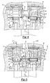
- Figure 2A shows a first thrust assembly 26 and a second thrust assembly 28.
- the eccentric movement of the roller 22 engages the first thrust assembly 26 and the second thrust assembly 28 and applies a load causing the first and second thrust assemblies 26 and 28 to move perpendicularly away from the lever 14, guided by a housing 61 that is attached to frame 11 by fasteners 34, (only one shown in Figure 1).
- This motion defines a first thrust axis 27 perpendicular to the lever axis 20 and roller axis 24 along which the first thrust assembly 26 moves.
- the axial movement of the first thrust assembly 26 along the first thrust axis 27 engages the brake pad 30 by way of a first thrust plate 62.
- axial movement of the second thrust assembly 28 along a second thrust axis 32 engages the brake pad 30 by way of a second thrust plate 60.
- the brake pad 30 then engages the brake disc 29.
- first return spring 31 and second return spring 33 drive the first and second thrust assemblies 26 and 28 to the original positions.
- the lever 14 and roller 22 also return to the original positions.
- the first and second return springs 31 and 33 restrain the first thrust assembly 26, second thrust assembly 28, roller 22 and lever 14 in the original positions when no input load L is being applied.
- the first thrust assembly 26 consists of internally threaded first nut 63 and externally threaded first screw 64.
- the first nut 63 is rotationally constrained by the housing 61, such that when the first screw 64 is rotated, the length of the first thrust assembly 26 along the thrust axis 27 is altered.
- the second thrust assembly 28 has a similar screw and nut arrangement where the second thrust assembly 28 consists of internally threaded second nut 65 and an externally threaded second screw 67 (shown in Figure 2B).
- the lengths of the first thrust assembly 26 and second thrust assembly 28 are synchronized by a rotational member 48, which is permanently engaged with the first and second screws 64 and 67 by way of a gear 68. If no constraint was in place the rotational member 48 might cause rotation of the first and second screws 64 and 67 lengthening the first and second thrust assemblies 26 and 28 until the brake pad 30 and brake disc 29 were touching.
- Figure 2B shows the slack adjustment system 12 with a locking mechanism 42 that selectively engages the gear 68 to prevent the first screw 64 and second screw 67 from being rotated and undesirably adjusting the gap between the brake pad 30 and the brake disc 29.
- the locking mechanism 42 includes a latch 54 mounted to a link 56, which may be a rod or the like, which is fixed to move with lever 14.
- the latch 54 may engage the gear 68 on rotational member 48 preventing rotation of the rotational member 48.
- the latch 54 engages the gear 68 when the brake is not applied, and when the brake is applied but the first thrust assembly 26 and second thrust assembly 28 have moved by less than the pre-defined slack such that no adjustment is required.
- the locking mechanism 42 When the brake is not applied, or during normal braking movement, as shown in Figure 3, the locking mechanism 42 is engaged and the rotational member 48 cannot rotate to lengthen the first thrust assembly 26 and second thrust assembly 28.
- the axial force applied to first screw 64 and second screw 67 by rotation of lever 14 axially drives the first thrust assembly 26 and second thrust assembly 28 along the first and second thrust axes 27 and 32 toward the brake disc 29.
- the locking mechanism 42 and latch 54 driven by the lever 14 via a link 56 move relative to the gear 68 on the outside of the rotational member 48 (shown in Figure 3 to be moving along an axis parallel to the first thrust axis 27, but alternatively could be moved radially away from the first thrust axis 27 by re-arranging the connecting link 56).
- the link 56 may be rotatably connected to the lever 14 such that when lever 14 is driven forward link 56 rotates to maintain the relative position between latch 54 and gear 68 at an equivalent height.
- the point at which the latch 54 disengages from the gear 68 is determined by the geometry of the link 56.
- the geometry is designed such that when a pre-defined slack between the brake pad 30 and disc 29 has been taken up, the latch 54 disengages from the gear 68.
- load starts to be applied to the first thrust assembly 26 and second thrust assembly 28 via the brake pad 30 that engages the brake disc 29.
- This load produces a friction torque between the first nut 63 and first screw 64, and the second nut 65 and the second screw 67, preventing any relative rotation and, hence, adjustment when the brake is applied, shown in Figure 4.
- the brake is released, all components are returned to their original positions by the return springs 31 and 33.
- the latch 54 engages gear 68 again and no adjustment of the length of the first thrust assembly 26 and second thrust assembly 28 takes place.
- the first thrust assembly 26 and second thrust assembly 28 must move a greater distance along the thrust axis 27 in order to engage the brake pad 30 with the brake disc 29.
- the first and second screws 64 and 67 are adjusted to increase the overall length of the thrust assembly 26, resulting in a constant distance being maintained between the brake pad 30 and brake disc 29.
- the adjuster system 12 of the present invention is utilized to adjust the slack in the brake assembly 10.
- the rotational member 48 includes a biasing member 44 and the gear 68 mounted in the housing 61.
- the biasing member 44 causes the gear 68 to rotate about a biasing axis 46.
- the biasing axis 46 is preferably parallel to and offset from the first thrust axis 27, but could be in any position or angle inside or outside the frame 11 where the rotational member 48 can still be engaged directly or indirectly to the first and second screws 64 and 67.
- the biasing member 44 is preferably a coil spring but may take other forms such as an electric motor, air motor, or the like.
- the gear 68 is mounted about the biasing member 44 and is driven by the biasing member 44 in a first rotational direction 50 about the biasing axis 46.
- the gear 68 engages with the first and second screws 64 and 67 preferably by gear teeth, but other means of engagement may be used.
- the first and second screws 64 and 67 rotate about the thrust axes 27 and 32 in a second rotational direction 52. That is, rotational member 48 rotates in a clockwise direction, which rotates the first and second screws 64 and 67 in a counter-clockwise direction, as illustrated in Figure 6. Rotation of the first and second screws 64 and 67 causes the first and second nuts 63 and 65 to move toward the brake pad 30, thereby lengthening the thrust assemblies 26 and 28, and decreasing the slack.
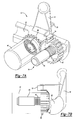
- Figures 7A and 7B show an alternate embodiment.
- the lever 14 is in a position when no load is being applied.
- Rotational member 48 is prevented from rotation by latch 54 that engages a first gear 66 on the first screw 64.
- First gear 66 meshes with the gear 68 on the rotation member 48.
- Latch 54 prevents rotation of first gear 66 and in turn prevents rotation of gear 68.
- a second gear meshes with gear 68, as shown in Figure 1, in a similar manner as the first gear 66.
- the second gear 70 is prevented from rotation by gear 68 that also acts to synchronize the first gear 66 with the second gear 70 ensuring that the first thrust assembly 26 and second thrust assembly 28 are adjusted the same length.
- Figures 8A and 8B show the lever 14 when the brake is applied and the thrust assembly 26 has moved through the pre-defined slack.
- the latch 54 disengages with first gear 66.
- the gear 68 is free to rotate from the torque created by the biasing member 44. As gear 68 rotates this cause the first gear 66 to rotate, thus rotating the first screw 64.
- the first gear 66 is driven in the counter-clockwise direction 52, lengthening the thrust assembly 26 and reducing the slack. A similar rotation occurs on for the second screw 67 lengthening the second thrust assembly 28 (not shown).
- Figure 9A and 9B show the lever 14, rotational member 48, latch 54, and the first gear 66 on the first screw 64 during a full brake position.
- the latch 54 has disengaged from the first gear 66.
- first thrust assembly 26 when the brake pad 30 and brake disc 29 are in contact load is applied through the first thrust assembly 26.
- the load prevents rotation of the first nut 63 and first screw 64 hence no adjustment occurs.
- second thrust assembly is prevented from rotation.
- the preferred directions of rotation are shown in Figure 6.
- Figure 10A shows another embodiment slack adjustment system 100 where a locking mechanism 102 is located adjacent the roller 22.
- the roller 22 is recessed within the base of the lever 14.
- an input load (illustrated by arrow L) is transferred to a lever 14.
- Applying the input load L rotates the lever 14 causing the roller 22 to rotate (illustrated by arrow R).
- Figure 10B shows the lever 14 and roller 22 with a cam 108 mounted on the end of the roller 22. The cam 108 rotates with the roller 22.
- the locking mechanism 102 includes a latch 110 that engages the first gear 66.
- a spring 114 drives the latch 110 into the first gear 66 to maintain engagement between the first gear 66 and the latch 110.
- Figure 12A shows the latch 110 and the spring 114 within a frame 11 for the brake assembly 10.
- the spring 114 is within a screw 118 that is threaded into the frame 11.
- the screw 118 can be rotated to adjust the force the spring 114 applies to the latch 110.
- Figure 12B shows the latch 110 within the frame 11 and contacting the first gear 66.
- the cam 108 and screw 118 are not shown so the engagement between the latch 110 and first gear 66 can be seen.
- Figure 12C shows the locking mechanism 102 including the latch 110 and screw 118 within the frame 11 with the cam 108 and first gear 66.
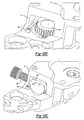
- Figure 13A shows the cam 108 engaging the latch 110 when no pressure is applied to the lever 14. Rotating the lever 14 rotates the cam 108 driving the latch 110 away from the first gear 66 as shown in Figure 13B. If there is only a minimal amount of slack in the brake system 10 then the roller 22 will not rotate far enough to disengage the latch 110 from the first gear 66. Tooth 111 on the latch 110 sits between teeth on the gear 66, preventing rotation, and hence preventing undesired adjustment. As the slack in the brake system increases the roller 22 must be rotated farther to engage the brakes. The farther the roller 22 rotates the more the cam 108 drives the latch 110 away from the first gear 66.
- Figure 13C shows the latch 110 and cam 108 when undesirable slack is in the system and the roller 22 rotates a sufficient amount to disengage the latch 110 from the first gear 66.
- a tooth 111 no longer engage between gear teeth on the gear 66, and no longer preventing the gear 66 from rotating.
- the position of the first gear 66 and latch 110 at this point are shown in Figure 14.
- the latch 110 is disengaged the first gear 66 can rotate freely to lengthen the thrust assemblies 26 and 28 adjusting the slack.
- Figure 13D shows the cam 108 and latch 110 when the roller is fully rotated.
- the cam 108 is designed such that once the latch 110 has disengaged from the gear 66 the cam 108 will not move the latch 110 further away from the first gear 66.
- the amount of slack in the brake system 10 is controlled by the distance that the cam 108 pushes the latch 110 away from the first gear 66.
- a biasing member 120 engages the first gear 66 through a gear 122 (shown in Figure 15).
- the biasing member 120 is preferably an air motor but may take other forms such as a spring, electric motor, or the like.
- the biasing member 120 rotates the first gear 66 when the latch 110 is disengaged. Rotation of the first gear 66 causes the thrust assemblies 26 and 28 to lengthen and decreases the slack in the brake system 10.
- the force used to adjust the slack adjustment system is 100 is independent of the load L applied to the lever.
- the biasing member 120 provides the load used to rotate the first gear 66. By providing an independent source to bias the slack adjustment system 100 the load L applied to the lever is not used, increasing the efficiency of the slack adjustment system 100.
Landscapes
- Engineering & Computer Science (AREA)
- General Engineering & Computer Science (AREA)
- Mechanical Engineering (AREA)
- Braking Arrangements (AREA)
Abstract
Description
- The present invention relates to an adjuster mechanism for a brake.
- As brake pads or a brake disc wear a gap between the brake pads and brake disc increases. Due to the increase in the gap between the brake pads and the brake disc a brake actuator must travel farther to engage the brake. In other words, there is more slack when the brake is applied, which causes the brakes to become less effective. In order to compensate for slack, a slack adjustment mechanism moves the brake pads closer to the brake disc prior to brake engagement. This adjustment assures a consistent amount of actuator travel in spite of brake pad wear.
- Conventional brake adjuster mechanisms use relatively complex mechanical assemblies to perform this function. Force from the brake actuator is commonly utilized to drive the adjuster mechanism, which may reduce brake effectiveness and efficiency.
- In addition, the adjuster mechanism may shift while the brake is not being applied. Shifting may cause undesirable brake pad wear, or further increase slack in the brake system, which may reduce the brake performance.
- Accordingly, it is desirable to provide an adjuster mechanism which is not effective when the brake is not being utilized.
- The slack adjustment system according to the present invention provides an adjustment mechanism which utilizes a biasing member to adjust slack in a braking system. The biasing member operates independently of the pressure applied by a brake actuator. A locking mechanism is utilized to secure the adjustment mechanism in place when adjustment is not desired. Additionally, the locking mechanism controls the desired amount of slack.
- The locking mechanism selectively engages an adjustment gear, or any rotational member engaged with the gear, to prevent the gear from being rotated and undesirably adjusting the gap between the brake pad and the brake disc. The locking mechanism prevents adjustment when the brake is not applied. The locking mechanism includes a latch interfitting with the gear to prevent rotation when engaged with the gear. The latch disengages from the gear after a predetermined amount of movement of the latch. Release of the locking mechanism allows the gear to rotate. The biasing member is mounted to engage and rotate the gear when the locking member is not preventing movement. The biasing member is of a type which applies a rotational force independent of the amount of pressure applied by the brake actuator. The biasing member may be a spring, electric motor, air powered motor or the like.
- The present invention therefore provides a method of automatically adjusting slack independent of the pressure applied to the brake system. In addition, a locking device prevents undesirable adjustment of slack in the brake system.
- The various features and advantages of this invention will become apparent to those skilled in the art from the following detailed description of the currently preferred embodiment. The drawings that accompany the detailed description can be briefly described as follows:
- Figure 1 is a sectional side-view of a brake assembly with one embodiment of a slack adjustment system according to the present invention;
- Figure 2A is a sectional plan-view of a brake assembly;
- Figure 2B is a perspective view of one embodiment of the slack adjustment system with the latch engaged on a rotational member;
- Figure 3 is a sectional plan-view of the slack adjustment system according to the present invention showing a gear moved forward by a distance equal to the desired amount of slack, with the latch still engaged with the rotational member;
- Figure 4 is a sectional plan view of the slack adjustment system according to the present invention showing all components in the brake fully applied position;
- Figure 5 is a sectional plan-view of the slack adjustment system according to the present invention shown in the disengaged position;
- Figure 6 is a sectional end-view of the rotational member and gear-train showing the preferred directions of rotation;
- Figure 7A is a perspective view of one embodiment of the slack adjustment system of the present invention in a non-braking position;
- Figure 7B is a side view of the Figure 7A embodiment of the slack adjustment system of the present invention in a non-braking position;
- Figure 8A is a perspective view of the Figure 7A embodiment of the slack adjustment system of the present invention in a partial braking position;
- Figure 8B is a side view of the slack adjustment system of Figure 8A;
- Figure 9A is a perspective view of the slack adjustment system of the Figure 7A embodiment of the present invention in a full braking position;
- Figure 9B is a side view of the slack adjustment system of Figure 9A;
- Figure 10A shows another embodiment of the slack adjustment system where a locking mechanism is located adjacent a roller;
- Figure 10B shows the Figure 10A embodiment of the slack adjustment system with a lever and roller having a cam mounted on the end of the roller;
- Figure 11 shows an embodiment of the slack adjustment system where the locking mechanism has a latch;
- Figure 12A shows a frame for the brake assembly with the latch and the spring;
- Figure 12B shows a frame for the brake assembly with the latch and the first gear;
- Figure 12C shows a frame for the brake assembly with the latch and the screw within the frame;
- Figure 13A shows the cam engaging the latch when no pressure is applied to the lever;
- Figure 13B shows the lever rotating the cam to drive the latch away from the first gear;
- Figure 13C shows the latch and cam when a sufficient amount slack is in the system to disengage the latch from the first gear;
- Figure 13D shows the cam and latch when the roller is fully rotated;
- Figure 14 shows the latch and gear when a sufficient amount slack is in the system to disengage the latch from the first gear; and
- Figure 15 shows a biasing member engaging the first gear.
- Figure 1 illustrates a
disc brake assembly 10 that utilizes aslack adjustment system 12 of the present invention. Thedisc brake assembly 10 has aframe 11, which encloses the internal components and bears the loads generated by them. As a driver operates a brake (not shown) an input load (illustrated by arrow L) is transferred to alever 14, through anopening 16 in theframe 11. Thelever 14 is rotatably supported by theframe 11 through abearing 18. Applying the input load L rotates thelever 14 about alever axis 20. That is, thelever 14 rotates clockwise about thelever axis 20, as illustrated in Figure 1. - A
cylindrical roller 22 is recessed within the base of thelever 14. Theroller 22 is eccentrically centered relative the center of rotation of thelever 14. That is, theroller 22 rotates about a roller axis 24 that is offset from thelever axis 20. When the input load L causes thelever 14 to rotate about thelever axis 20 theroller 22 rotates about the roller axis 24. Because the roller axis 24 is offset from thelever axis 20 theroller 22 moves in an arc relative to the lever axis 20 (theposition 15 illustrated in phantom shows the extreme of travel available to the lever 14). - Figure 2A shows a
first thrust assembly 26 and asecond thrust assembly 28. The eccentric movement of theroller 22 engages thefirst thrust assembly 26 and thesecond thrust assembly 28 and applies a load causing the first andsecond thrust assemblies lever 14, guided by ahousing 61 that is attached to frame 11 by fasteners 34, (only one shown in Figure 1). This motion defines afirst thrust axis 27 perpendicular to thelever axis 20 and roller axis 24 along which thefirst thrust assembly 26 moves. The axial movement of thefirst thrust assembly 26 along thefirst thrust axis 27 engages thebrake pad 30 by way of afirst thrust plate 62. Similarly, axial movement of thesecond thrust assembly 28 along asecond thrust axis 32 engages thebrake pad 30 by way of asecond thrust plate 60. Thebrake pad 30 then engages thebrake disc 29. - When the driver releases the brake, the input load L is reduced and a
first return spring 31 andsecond return spring 33 drive the first andsecond thrust assemblies lever 14 androller 22 also return to the original positions. The first and second return springs 31 and 33 restrain thefirst thrust assembly 26,second thrust assembly 28,roller 22 andlever 14 in the original positions when no input load L is being applied. - As a result of use,
brake pad 30 wears away and a gap between thebrake pad 30 and thebrake disc 29 becomes greater over time. The first andsecond thrust assemblies brake pad 30 to engage thebrake disc 29. To eliminate the need for thebrake pad 30 to travel further the first andsecond thrust assemblies brake pad 30 andbrake disc 29 over time. Thefirst thrust assembly 26 consists of internally threadedfirst nut 63 and externally threadedfirst screw 64. Thefirst nut 63 is rotationally constrained by thehousing 61, such that when thefirst screw 64 is rotated, the length of thefirst thrust assembly 26 along thethrust axis 27 is altered. Thesecond thrust assembly 28 has a similar screw and nut arrangement where thesecond thrust assembly 28 consists of internally threadedsecond nut 65 and an externally threaded second screw 67 (shown in Figure 2B). The lengths of thefirst thrust assembly 26 andsecond thrust assembly 28 are synchronized by arotational member 48, which is permanently engaged with the first andsecond screws 64 and 67 by way of agear 68. If no constraint was in place therotational member 48 might cause rotation of the first andsecond screws 64 and 67 lengthening the first andsecond thrust assemblies brake pad 30 andbrake disc 29 were touching. - Figure 2B shows the
slack adjustment system 12 with alocking mechanism 42 that selectively engages thegear 68 to prevent thefirst screw 64 and second screw 67 from being rotated and undesirably adjusting the gap between thebrake pad 30 and thebrake disc 29. Thelocking mechanism 42 includes alatch 54 mounted to alink 56, which may be a rod or the like, which is fixed to move withlever 14. Thelatch 54 may engage thegear 68 onrotational member 48 preventing rotation of therotational member 48. Thelatch 54 engages thegear 68 when the brake is not applied, and when the brake is applied but thefirst thrust assembly 26 andsecond thrust assembly 28 have moved by less than the pre-defined slack such that no adjustment is required. - When the brake is not applied, or during normal braking movement, as shown in Figure 3, the
locking mechanism 42 is engaged and therotational member 48 cannot rotate to lengthen thefirst thrust assembly 26 andsecond thrust assembly 28. The axial force applied tofirst screw 64 and second screw 67 by rotation oflever 14 axially drives thefirst thrust assembly 26 andsecond thrust assembly 28 along the first and second thrust axes 27 and 32 toward thebrake disc 29. Thelocking mechanism 42 and latch 54 driven by thelever 14 via alink 56, move relative to thegear 68 on the outside of the rotational member 48 (shown in Figure 3 to be moving along an axis parallel to thefirst thrust axis 27, but alternatively could be moved radially away from thefirst thrust axis 27 by re-arranging the connecting link 56). Thelink 56 may be rotatably connected to thelever 14 such that whenlever 14 is drivenforward link 56 rotates to maintain the relative position betweenlatch 54 andgear 68 at an equivalent height. - The point at which the
latch 54 disengages from thegear 68 is determined by the geometry of thelink 56. The geometry is designed such that when a pre-defined slack between thebrake pad 30 anddisc 29 has been taken up, thelatch 54 disengages from thegear 68. Simultaneously, load starts to be applied to thefirst thrust assembly 26 andsecond thrust assembly 28 via thebrake pad 30 that engages thebrake disc 29. This load produces a friction torque between thefirst nut 63 andfirst screw 64, and thesecond nut 65 and the second screw 67, preventing any relative rotation and, hence, adjustment when the brake is applied, shown in Figure 4. When the brake is released, all components are returned to their original positions by the return springs 31 and 33. Thelatch 54 engagesgear 68 again and no adjustment of the length of thefirst thrust assembly 26 andsecond thrust assembly 28 takes place. - As the
brake pad 30 wears, the slack between thebrake pad 30 and thebrake disc 29 increases, and thefirst thrust assembly 26 andsecond thrust assembly 28 must move a greater distance along thethrust axis 27 in order to engage thebrake pad 30 with thebrake disc 29. To compensate for the wear on thebrake pad 30, the first andsecond screws 64 and 67 are adjusted to increase the overall length of thethrust assembly 26, resulting in a constant distance being maintained between thebrake pad 30 andbrake disc 29. - Referring to Figure 5, the
adjuster system 12 of the present invention is utilized to adjust the slack in thebrake assembly 10. When thelocking mechanism 42 is released, as shown, therotational member 48 and first andsecond screws 64 and 67 can rotate. Therotational member 48 includes a biasingmember 44 and thegear 68 mounted in thehousing 61. The biasingmember 44 causes thegear 68 to rotate about a biasingaxis 46. The biasingaxis 46 is preferably parallel to and offset from thefirst thrust axis 27, but could be in any position or angle inside or outside theframe 11 where therotational member 48 can still be engaged directly or indirectly to the first andsecond screws 64 and 67. The biasingmember 44 is preferably a coil spring but may take other forms such as an electric motor, air motor, or the like. Thegear 68 is mounted about the biasingmember 44 and is driven by the biasingmember 44 in a firstrotational direction 50 about the biasingaxis 46. Thegear 68 engages with the first andsecond screws 64 and 67 preferably by gear teeth, but other means of engagement may be used. The first andsecond screws 64 and 67 rotate about the thrust axes 27 and 32 in a secondrotational direction 52. That is,rotational member 48 rotates in a clockwise direction, which rotates the first andsecond screws 64 and 67 in a counter-clockwise direction, as illustrated in Figure 6. Rotation of the first andsecond screws 64 and 67 causes the first andsecond nuts brake pad 30, thereby lengthening thethrust assemblies - Figures 7A and 7B show an alternate embodiment. The
lever 14 is in a position when no load is being applied.Rotational member 48 is prevented from rotation bylatch 54 that engages afirst gear 66 on thefirst screw 64.First gear 66 meshes with thegear 68 on therotation member 48.Latch 54 prevents rotation offirst gear 66 and in turn prevents rotation ofgear 68. A second gear meshes withgear 68, as shown in Figure 1, in a similar manner as thefirst gear 66. Thesecond gear 70 is prevented from rotation bygear 68 that also acts to synchronize thefirst gear 66 with thesecond gear 70 ensuring that thefirst thrust assembly 26 andsecond thrust assembly 28 are adjusted the same length. - Figures 8A and 8B show the
lever 14 when the brake is applied and thethrust assembly 26 has moved through the pre-defined slack. Thelatch 54 disengages withfirst gear 66. Thegear 68 is free to rotate from the torque created by the biasingmember 44. Asgear 68 rotates this cause thefirst gear 66 to rotate, thus rotating thefirst screw 64. Thefirst gear 66 is driven in thecounter-clockwise direction 52, lengthening thethrust assembly 26 and reducing the slack. A similar rotation occurs on for the second screw 67 lengthening the second thrust assembly 28 (not shown). - Figure 9A and 9B show the
lever 14,rotational member 48,latch 54, and thefirst gear 66 on thefirst screw 64 during a full brake position. Thelatch 54 has disengaged from thefirst gear 66. However, when thebrake pad 30 andbrake disc 29 are in contact load is applied through thefirst thrust assembly 26. The load prevents rotation of thefirst nut 63 andfirst screw 64 hence no adjustment occurs. Likewise the second thrust assembly is prevented from rotation. The preferred directions of rotation are shown in Figure 6. - When the brake is released, if there is still excess slack when all load is released from the
thrust assembly 26, therotational member 48 andfirst screw 64 will be rotated further as shown in Figures 8A and 8B. Thefirst screw 64 will continue to rotate until the travel of thethrust assembly 26 becomes equal to the predefined slack. The second screw 67 (not shown) will also rotate. At this point thelatch 54 then re-engages with thefirst gear 66 preventing any further rotation. - Figure 10A shows another embodiment
slack adjustment system 100 where alocking mechanism 102 is located adjacent theroller 22. Theroller 22 is recessed within the base of thelever 14. As a driver operates a brake (not shown) an input load (illustrated by arrow L) is transferred to alever 14. Applying the input load L rotates thelever 14 causing theroller 22 to rotate (illustrated by arrow R). Figure 10B shows thelever 14 androller 22 with acam 108 mounted on the end of theroller 22. Thecam 108 rotates with theroller 22. - Referring to Figure 11, the
locking mechanism 102 includes alatch 110 that engages thefirst gear 66. Aspring 114 drives thelatch 110 into thefirst gear 66 to maintain engagement between thefirst gear 66 and thelatch 110. - Figure 12A shows the
latch 110 and thespring 114 within aframe 11 for thebrake assembly 10. Thespring 114 is within ascrew 118 that is threaded into theframe 11. Thescrew 118 can be rotated to adjust the force thespring 114 applies to thelatch 110. Figure 12B shows thelatch 110 within theframe 11 and contacting thefirst gear 66. Thecam 108 and screw 118 are not shown so the engagement between thelatch 110 andfirst gear 66 can be seen. Figure 12C shows thelocking mechanism 102 including thelatch 110 and screw 118 within theframe 11 with thecam 108 andfirst gear 66. - Figure 13A shows the
cam 108 engaging thelatch 110 when no pressure is applied to thelever 14. Rotating thelever 14 rotates thecam 108 driving thelatch 110 away from thefirst gear 66 as shown in Figure 13B. If there is only a minimal amount of slack in thebrake system 10 then theroller 22 will not rotate far enough to disengage thelatch 110 from thefirst gear 66.Tooth 111 on thelatch 110 sits between teeth on thegear 66, preventing rotation, and hence preventing undesired adjustment. As the slack in the brake system increases theroller 22 must be rotated farther to engage the brakes. The farther theroller 22 rotates the more thecam 108 drives thelatch 110 away from thefirst gear 66. Figure 13C shows thelatch 110 andcam 108 when undesirable slack is in the system and theroller 22 rotates a sufficient amount to disengage thelatch 110 from thefirst gear 66. As shown atooth 111 no longer engage between gear teeth on thegear 66, and no longer preventing thegear 66 from rotating. The position of thefirst gear 66 and latch 110 at this point are shown in Figure 14. When thelatch 110 is disengaged thefirst gear 66 can rotate freely to lengthen thethrust assemblies - Figure 13D shows the
cam 108 and latch 110 when the roller is fully rotated. Thecam 108 is designed such that once thelatch 110 has disengaged from thegear 66 thecam 108 will not move thelatch 110 further away from thefirst gear 66. Thus, the amount of slack in thebrake system 10 is controlled by the distance that thecam 108 pushes thelatch 110 away from thefirst gear 66. - A biasing member 120 (not shown) engages the
first gear 66 through a gear 122 (shown in Figure 15). The biasing member 120 is preferably an air motor but may take other forms such as a spring, electric motor, or the like. The biasing member 120 rotates thefirst gear 66 when thelatch 110 is disengaged. Rotation of thefirst gear 66 causes thethrust assemblies brake system 10. The force used to adjust the slack adjustment system is 100 is independent of the load L applied to the lever. The biasing member 120 provides the load used to rotate thefirst gear 66. By providing an independent source to bias theslack adjustment system 100 the load L applied to the lever is not used, increasing the efficiency of theslack adjustment system 100. - The foregoing description is only illustrative of the principles of the invention. Many modifications and variations of the present invention are possible in light of the above teachings. The preferred embodiments of this invention have been disclosed, however, so that one of ordinary skill in the art would recognize that certain modifications would come within the scope of this invention. It is, therefore, to be understood that within the scope of the appended claims, the invention may be practiced otherwise than as specially described. For that reason the following claims should be studied to determine the true scope and content of this invention.
Claims (15)
- A slack adjustment system for a disc brake comprising:a cam mounted on an end of a lever;a plurality of gears engaged with a rotational member for rotation about a plurality of thrust axes; anda locking mechanism mounted adjacent said cam to selectively engage at least one of said plurality of gears to prevent rotation thereof.
- The system as recited in claim 1, wherein said cam disengages said locking mechanism from one of said plurality of gears.
- A slack adjustment system for a disc brake comprising:a lever mounted for rotation about a lever axis;a rotational member biased in a first direction about a biasing axis wherein said bias is independent of a force applied to said lever;a plurality of gears engaged with said rotational member for rotation in a second direction about a plurality of thrust axes parallel to said biasing axis; anda locking mechanism mounted adjacent said lever to selectively engage at least one of said plurality of gears to prevent rotation thereof.
- The system as recited in claim 3, wherein said locking mechanism couples with teeth of said at least one of said plurality of gears.
- The system as recited in claim 3 or 4, wherein said locking mechanism disengages said one of said plurality of gears in response to rotation of said lever about said lever axis.
- The system as recited in claim 5, wherein said lever rotates through a predetermined amount before said locking mechanism is disengaged.
- The system as recited in any preceding claim, wherein said locking mechanism engages between teeth on said at least one of said plurality of gears to prevent rotation.
- The system as recited in any preceding claim, wherein said locking mechanism is a wedge.
- The system as recited in any preceding claim, wherein a spring biases said locking mechanism towards said one of said plurality of gears.
- The system as recited in claim 9, wherein a cam on said lever disengages said locking mechanism from one of said plurality of gears.
- The system as recited in any of claims I to 8, wherein said biasing member is an air motor.
- A disc brake comprising:a slack adjustment system having a rotational member biased in a first direction about a biasing axis;a plurality of gears engaged with said rotational member for rotation in a second direction about a plurality of thrust axes parallel to said biasing axis; anda locking mechanism mounted to selectively engage at least one of said plurality of gears to prevent rotation thereof.
- The system as recited in claim 12, wherein said locking mechanism disengages from said one of said plurality of gears in response to rotation of a lever about a lever axis.
- The system as recited in claim 12 or 13, wherein a or the lever rotates through a predetermined amount before said locking mechanism is disengaged.
- The system as recited in any of claims 12 to 14, wherein said locking mechanism engages between teeth on said at least one of said plurality of gears to prevent rotation.
Applications Claiming Priority (1)
| Application Number | Priority Date | Filing Date | Title |
|---|---|---|---|
| US11/199,003 US7931129B2 (en) | 2003-01-31 | 2005-08-08 | Rapid take up and vibration proof adjuster mechanism |
Publications (2)
| Publication Number | Publication Date |
|---|---|
| EP1752680A2 true EP1752680A2 (en) | 2007-02-14 |
| EP1752680A3 EP1752680A3 (en) | 2007-04-25 |
Family
ID=37453387
Family Applications (1)
| Application Number | Title | Priority Date | Filing Date |
|---|---|---|---|
| EP06253494A Withdrawn EP1752680A3 (en) | 2005-08-08 | 2006-07-04 | Rapid take up and vibration proof adjuster mechanism |
Country Status (5)
| Country | Link |
|---|---|
| US (1) | US7931129B2 (en) |
| EP (1) | EP1752680A3 (en) |
| JP (1) | JP2007051776A (en) |
| CN (1) | CN1912416A (en) |
| BR (1) | BRPI0603163A (en) |
Cited By (1)
| Publication number | Priority date | Publication date | Assignee | Title |
|---|---|---|---|---|
| US9002603B2 (en) | 2010-12-14 | 2015-04-07 | Zf Friedrichshafen Ag | Method for the operation of a transmission device in a vehicle drive train when a request is made to change gears |
Families Citing this family (15)
| Publication number | Priority date | Publication date | Assignee | Title |
|---|---|---|---|---|
| US20100252380A1 (en) * | 2009-04-03 | 2010-10-07 | Bill Nguyen | Bicycle or motorcycle brake lever lock |
| US8820490B2 (en) | 2012-03-16 | 2014-09-02 | Arvinmeritor Technology, Llc | Manual adjuster for automatic slack adjuster |
| DE102012102583A1 (en) * | 2012-03-26 | 2013-09-26 | Knorr-Bremse Systeme für Nutzfahrzeuge GmbH | Adjustment device for a disc brake |
| JP5944583B2 (en) * | 2012-07-31 | 2016-07-05 | サンシン ブレーキ カンパニー リミティドSangsin Brake Co., Ltd. | Vehicle disc brake having guide pins |
| KR101525147B1 (en) * | 2012-07-31 | 2015-06-03 | 상신브레이크주식회사 | Disc brake for vehicle having gear connection |
| DE102012108676B3 (en) * | 2012-09-17 | 2014-02-06 | Knorr-Bremse Systeme für Nutzfahrzeuge GmbH | Disc brake with a wear adjusting device |
| CN103423347A (en) * | 2013-07-03 | 2013-12-04 | 李应声 | Gap adjusting mechanism based on air pressure disc brake |
| CN103486167A (en) * | 2013-07-03 | 2014-01-01 | 李应声 | Braking-clearance compensating mechanism based on atmospheric-pressure disc type brake |
| US10058032B2 (en) | 2015-07-31 | 2018-08-28 | Parker-Hannifin Corporation | Mowing machine brake apparatus with slideable engagement |
| DE102015114546A1 (en) * | 2015-09-01 | 2017-03-02 | Knorr-Bremse Systeme für Nutzfahrzeuge GmbH | Disc brake for a vehicle, in particular for a commercial vehicle |
| FR3045754B1 (en) * | 2015-12-17 | 2019-06-14 | Foundation Brakes France | ELECTROMECHANIC ACTUATOR WITH REDUCED SIZE FOR DISC BRAKE |
| CN107366697B (en) * | 2017-08-30 | 2023-08-01 | 隆中控股集团股份有限公司 | Braking mechanism |
| KR102022403B1 (en) * | 2018-01-17 | 2019-09-18 | 현대모비스 주식회사 | Brake apparatus for vehicle |
| KR102404524B1 (en) * | 2020-08-25 | 2022-06-02 | 현대모비스 주식회사 | Parking brake apparatus for vehicle |
| KR20220162461A (en) * | 2021-06-01 | 2022-12-08 | 현대모비스 주식회사 | Parking brake apparatus for vehicle |
Family Cites Families (10)
| Publication number | Priority date | Publication date | Assignee | Title |
|---|---|---|---|---|
| US5201387A (en) * | 1991-05-22 | 1993-04-13 | Allied-Signal Inc. | Disc brake with variable width caliper and powered actuation |
| DE4334914A1 (en) | 1993-10-13 | 1995-04-20 | Knorr Bremse Systeme | Air operated disc brake |
| DE59508013D1 (en) * | 1994-01-18 | 2000-04-20 | Meritor Automotive Inc | Application device for a disc brake, especially for heavy commercial vehicles |
| US5722516A (en) * | 1996-11-12 | 1998-03-03 | Meritor Heavy Vehicle Systems, Llc | Disc brake with rigid connection between load plate and adjusting piston |
| DE19807328C2 (en) * | 1998-02-20 | 2003-08-28 | Lucas Ind Plc | Electromechanically actuated disc brake |
| JP4271852B2 (en) * | 1998-03-05 | 2009-06-03 | コンティネンタル・テーベス・アクチエンゲゼルシヤフト・ウント・コンパニー・オッフェネ・ハンデルスゲゼルシヤフト | Electromechanical control unit for disc brakes |
| DE19945543A1 (en) * | 1999-09-23 | 2001-03-29 | Continental Teves Ag & Co Ohg | Actuating unit for an electromechanically actuated disc brake |
| CN1168913C (en) * | 1999-11-18 | 2004-09-29 | Skf工程研究中心公司 | Actuator driving method and disc brake caliper driving method |
| SE517117C2 (en) * | 1999-12-02 | 2002-04-16 | Haldex Brake Prod Ab | DISC BRAKE |
| US6955246B2 (en) | 2003-01-31 | 2005-10-18 | Arvinmeritor Technology, Llc | Rapid take up and vibration proof adjuster mechanism |
-
2005
- 2005-08-08 US US11/199,003 patent/US7931129B2/en not_active Expired - Fee Related
-
2006
- 2006-07-04 EP EP06253494A patent/EP1752680A3/en not_active Withdrawn
- 2006-08-04 CN CNA2006101038726A patent/CN1912416A/en active Pending
- 2006-08-07 JP JP2006214759A patent/JP2007051776A/en active Pending
- 2006-08-08 BR BRPI0603163-3A patent/BRPI0603163A/en not_active Application Discontinuation
Non-Patent Citations (1)
| Title |
|---|
| None |
Cited By (1)
| Publication number | Priority date | Publication date | Assignee | Title |
|---|---|---|---|---|
| US9002603B2 (en) | 2010-12-14 | 2015-04-07 | Zf Friedrichshafen Ag | Method for the operation of a transmission device in a vehicle drive train when a request is made to change gears |
Also Published As
| Publication number | Publication date |
|---|---|
| US20050269171A1 (en) | 2005-12-08 |
| JP2007051776A (en) | 2007-03-01 |
| CN1912416A (en) | 2007-02-14 |
| EP1752680A3 (en) | 2007-04-25 |
| US7931129B2 (en) | 2011-04-26 |
| BRPI0603163A (en) | 2007-03-27 |
Similar Documents
| Publication | Publication Date | Title |
|---|---|---|
| US7931129B2 (en) | Rapid take up and vibration proof adjuster mechanism | |
| US6955246B2 (en) | Rapid take up and vibration proof adjuster mechanism | |
| RU2095657C1 (en) | Brake lever for securing to spline shaft with s-shaped expansion cam of car drum brake | |
| CN101391604B (en) | Single motor electronic wedge brake system locking parking force | |
| US7588128B2 (en) | Self-boosting electromechanical vehicle brake | |
| US20070151818A1 (en) | Electromechanically actuated parking brake | |
| US10161466B2 (en) | Brake device | |
| US7484601B2 (en) | Self-boosting electromechanical disk brake | |
| CN116529499B (en) | Braking device | |
| JP2001503841A (en) | Disc brake with gear-driven adjusting piston | |
| WO2010059423A1 (en) | Self-setting automatic slack adjuster with increased durability | |
| US8393440B2 (en) | Brake device having an elastic energy accumulator | |
| US11994182B2 (en) | Electro-mechanical brake | |
| EP4098903B1 (en) | Brake apparatus and automobile | |
| US8002088B2 (en) | Self boosting electromechanical friction brake | |
| KR102443769B1 (en) | High-efficiency actuator for electronic parking brake with magnetic restraint function | |
| RU2221174C2 (en) | Brake drum with automatic wear adjuster and device for selective release and locking | |
| US6293371B1 (en) | Disc brake assembly | |
| US3482661A (en) | Automatic self-adjusting mechanism for disk brakes | |
| JPH10318305A (en) | Adjuster for disc brake device | |
| JP2004068976A (en) | Wedge-operated brake device | |
| US4483424A (en) | Automatic slack adjuster | |
| WO2025086010A1 (en) | Wear adjuster for braking system | |
| JP2004211844A (en) | Disc brake device | |
| JP2004239331A (en) | Disc brake device with parking brake mechanism |
Legal Events
| Date | Code | Title | Description |
|---|---|---|---|
| PUAI | Public reference made under article 153(3) epc to a published international application that has entered the european phase |
Free format text: ORIGINAL CODE: 0009012 |
|
| AK | Designated contracting states |
Kind code of ref document: A2 Designated state(s): AT BE BG CH CY CZ DE DK EE ES FI FR GB GR HU IE IS IT LI LT LU LV MC NL PL PT RO SE SI SK TR |
|
| AX | Request for extension of the european patent |
Extension state: AL BA HR MK YU |
|
| PUAL | Search report despatched |
Free format text: ORIGINAL CODE: 0009013 |
|
| AK | Designated contracting states |
Kind code of ref document: A3 Designated state(s): AT BE BG CH CY CZ DE DK EE ES FI FR GB GR HU IE IS IT LI LT LU LV MC NL PL PT RO SE SI SK TR |
|
| AX | Request for extension of the european patent |
Extension state: AL BA HR MK YU |
|
| 17P | Request for examination filed |
Effective date: 20071012 |
|
| 17Q | First examination report despatched |
Effective date: 20071112 |
|
| AKX | Designation fees paid |
Designated state(s): AT BE BG CH CY CZ DE DK EE ES FI FR GB GR HU IE IS IT LI LT LU LV MC NL PL PT RO SE SI SK TR |
|
| GRAP | Despatch of communication of intention to grant a patent |
Free format text: ORIGINAL CODE: EPIDOSNIGR1 |
|
| INTG | Intention to grant announced |
Effective date: 20160609 |
|
| STAA | Information on the status of an ep patent application or granted ep patent |
Free format text: STATUS: GRANT OF PATENT IS INTENDED |
|
| STAA | Information on the status of an ep patent application or granted ep patent |
Free format text: STATUS: THE APPLICATION IS DEEMED TO BE WITHDRAWN |
|
| 18D | Application deemed to be withdrawn |
Effective date: 20161020 |