EP1752641A1 - "Engine control method and apparatus capable of performing said method" - Google Patents
"Engine control method and apparatus capable of performing said method" Download PDFInfo
- Publication number
- EP1752641A1 EP1752641A1 EP05017539A EP05017539A EP1752641A1 EP 1752641 A1 EP1752641 A1 EP 1752641A1 EP 05017539 A EP05017539 A EP 05017539A EP 05017539 A EP05017539 A EP 05017539A EP 1752641 A1 EP1752641 A1 EP 1752641A1
- Authority
- EP
- European Patent Office
- Prior art keywords
- egr
- rate
- engine
- misfire
- crankshaft
- Prior art date
- Legal status (The legal status is an assumption and is not a legal conclusion. Google has not performed a legal analysis and makes no representation as to the accuracy of the status listed.)
- Granted
Links
Images


Classifications
-
- F—MECHANICAL ENGINEERING; LIGHTING; HEATING; WEAPONS; BLASTING
- F02—COMBUSTION ENGINES; HOT-GAS OR COMBUSTION-PRODUCT ENGINE PLANTS
- F02D—CONTROLLING COMBUSTION ENGINES
- F02D41/00—Electrical control of supply of combustible mixture or its constituents
- F02D41/0025—Controlling engines characterised by use of non-liquid fuels, pluralities of fuels, or non-fuel substances added to the combustible mixtures
- F02D41/0047—Controlling exhaust gas recirculation [EGR]
- F02D41/005—Controlling exhaust gas recirculation [EGR] according to engine operating conditions
-
- F—MECHANICAL ENGINEERING; LIGHTING; HEATING; WEAPONS; BLASTING
- F02—COMBUSTION ENGINES; HOT-GAS OR COMBUSTION-PRODUCT ENGINE PLANTS
- F02D—CONTROLLING COMBUSTION ENGINES
- F02D41/00—Electrical control of supply of combustible mixture or its constituents
- F02D41/02—Circuit arrangements for generating control signals
- F02D41/14—Introducing closed-loop corrections
- F02D41/1497—With detection of the mechanical response of the engine
- F02D41/1498—With detection of the mechanical response of the engine measuring engine roughness
-
- F—MECHANICAL ENGINEERING; LIGHTING; HEATING; WEAPONS; BLASTING
- F02—COMBUSTION ENGINES; HOT-GAS OR COMBUSTION-PRODUCT ENGINE PLANTS
- F02D—CONTROLLING COMBUSTION ENGINES
- F02D2200/00—Input parameters for engine control
- F02D2200/02—Input parameters for engine control the parameters being related to the engine
- F02D2200/10—Parameters related to the engine output, e.g. engine torque or engine speed
- F02D2200/1012—Engine speed gradient
-
- F—MECHANICAL ENGINEERING; LIGHTING; HEATING; WEAPONS; BLASTING
- F02—COMBUSTION ENGINES; HOT-GAS OR COMBUSTION-PRODUCT ENGINE PLANTS
- F02D—CONTROLLING COMBUSTION ENGINES
- F02D2200/00—Input parameters for engine control
- F02D2200/02—Input parameters for engine control the parameters being related to the engine
- F02D2200/10—Parameters related to the engine output, e.g. engine torque or engine speed
- F02D2200/1015—Engines misfires
-
- Y—GENERAL TAGGING OF NEW TECHNOLOGICAL DEVELOPMENTS; GENERAL TAGGING OF CROSS-SECTIONAL TECHNOLOGIES SPANNING OVER SEVERAL SECTIONS OF THE IPC; TECHNICAL SUBJECTS COVERED BY FORMER USPC CROSS-REFERENCE ART COLLECTIONS [XRACs] AND DIGESTS
- Y02—TECHNOLOGIES OR APPLICATIONS FOR MITIGATION OR ADAPTATION AGAINST CLIMATE CHANGE
- Y02T—CLIMATE CHANGE MITIGATION TECHNOLOGIES RELATED TO TRANSPORTATION
- Y02T10/00—Road transport of goods or passengers
- Y02T10/10—Internal combustion engine [ICE] based vehicles
- Y02T10/40—Engine management systems
Definitions
- the present invention relates to an engine control method, more particularly to a method for controlling and/or correcting a rate of recirculated exhaust gas without causing combustion instability.
- Exhaust gas recirculation - EGR - is a well-known method to reduce NOx emissions.
- Current approaches for EGR are based on calibrated EGR rates. That is, the EGR ratio, i.e. the ratio of recirculated exhaust gas to fresh air, is calibrated on the relevant engine at the time of production. High EGR rates can have a negative impact on combustion stability and lead to misfires. Therefore, when calibrating an EGR rate for a certain type of engine, two major constraints apply. Higher EGR rates allow for maximal NOx reduction. However, higher EGR rates increase the possibility of misfires.
- the optimal EGR rate might work for some engines of a relevant engine type, while for other engines or under conditions different from the conditions applied when calculating the optimal EGR rate the same optimal EGR rate might induce undesired misfires or the optimal EGR rate might work for most engines during a certain amount of time while, once the engines are further operated beyond this amount of time, undesired misfires increase. Accordingly, in practice, a suboptimal EGR rate is calibrated to all engines of the same or a sufficiently similar type in order to prevent misfires from occurring.
- US 6,367,462 discloses a torque management control that coordinates engine throttle, spark and EGR under predefined highly throttled conditions so as to maximize the fuel economy improvement of EGR without degrading engine performance.
- EGR is increased to a level that maximises the fuel economy improvement without causing combustion instability, and the throttle position and spark timing are controlled to compensate for the anticipated torque loss while increasing volumetric efficiency and reducing pumping losses.
- engine throttle position is controlled to regulate the estimated engine output torque in accordance with the driver requested output torque.
- throttle control alone is used to regulate the output torque
- the throttle position is maintained and spark timing is used to regulate the output torque.
- the above object of the invention is achieved by carrying out the method having the features defined in claim 1.
- the engine control method more particularly the method for controlling an exhaust gas rate - EGR rate - for an internal combustion engine, according to the invention is characterised in the method comprising the steps of obtaining a value indicative of a combustion stability, hereinafter in short referred to as "misfire rate", and correcting the EGR rate on account of said value, i.e. on account of said "misfire rate".
- misfire rate being used synonymously for "a value indicative of combustion stability
- "misfire” or “misfires” in turn will be used synonymously for "decreased combustion stability”.
- the present invention is particularly concerned with providing a solution which directly links the occurrence of misfire or more specifically, the frequency of occurrence of misfire, basically resulting from excess EGR rate, to the EGR rate, therefore allowing for an EGR rate to be applied to the engine which would result in NOx reductions and misfires being minimised or at least significantly reduced.
- the misfire rate is obtained by applying a derivative of a rotational speed of a crankshaft of the engine controlled by the method. It has to be understood that observing the rotational speed of the crankshaft is only one method for obtaining a measure indicative of a misfire rate.
- the misfire rate is obtained only when a desired EGR rate (EGR demand) exceeds a predetermined EGR demand threshold and/or the engine is operated in quasi steady state conditions. Furthermore, while it is possible to obtain the misfire rate even during transient condition, the misfire rate is preferably only applied when the EGR demand exceeds a predetermined EGR demand threshold and the engine is operated in quasi steady state conditions. This ensures that the method according to the invention is applied only under conditions which have been recognised as providing sufficiently manageable circumstances and effects.
- said quasi steady state operation is recognised by torque changes of the engine, during a predetermined time interval, not exceeding a predetermined torque threshold.
- said correction of the EGR rate on account of said misfire rate is obtained by applying a misfire gain derived from said misfire rate, wherein said misfire gain is arithmetically combined, more particularly multiplicatively combined, with said EGR demand, and wherein said misfire gain is set to a neutral value, such as "1.0" for multiplicative combination, on account of said EGR demand not exceeding said predetermined EGR demand threshold or on account of the engine not operating in quasi steady state conditions.
- these means for performing the method steps comprise a sensor, preferably a motion sensor or acceleration sensor, associated to a crankshaft of the engine controlled by the apparatus, provided as a means for obtaining a value representative of the crankshaft rotation and/or the crankshaft acceleration.
- said means comprise at least one differentiator, more particularly said at least one differentiator and a filter, more particularly a low-pass filter, provided for obtaining the misfire rate by applying a derivative of a rotational speed of the crankshaft of the engine.
- said means comprise threshold means, provided for asserting if an EGR demand exceeds a predetermined EGR demand threshold and/or if torque changes of the engine during a predetermined time interval exceed a predetermined torque threshold.
- An output of these threshold means preferably logically combined, for example combined by means of an AND-Gate, beneficially functions as a trigger for applying the correction of the EGR rate on account of the misfire rate detected, i.e. as a trigger for applying the control scheme of the invention to the engine control.
- the invention also encompasses the implementation of the invention as a computer program with the appropriate computer readable program code for implementing the method steps described above and a respective computer program product, such as a storage medium, comprising said computer program or computer readable program code.
- Fig. 1 is a simplified block diagram of a combustion engine 10, where a motor block 12 comprises a number of cylinders 14 and a crank shaft 16. Upstream of the motor block 12 is an intake manifold 18, a throttle 20, a fresh air cooler 22, and an air filter 24 functioning as fresh air intake 26. Downstream of the motor block 12 is an exhaust manifold 28 and an exhaust line 30.
- At least part of the exhaust gas leaving the engine 10 through the exhaust manifold 28 is recirculated from the exhaust manifold via an EGR valve 32, and more specifically via an EGR valve 32 and an EGR cooler 34, to the intake manifold 18 and from there back into the engine 10.
- crankshaft motion sensor 36 is provided and associated with the crankshaft 16 for detecting a crankshaft motion, such as crankshaft angle, crankshaft rotation or crankshaft acceleration, etc.
- the output of the crankshaft motion sensor 36 is indicative of an injection speed 37.
- the crankshaft motion sensor 36 is connected to a crankshaft motion processing means 38, the injection speed 37 being an input to the crankshaft motion processing means 38 and an output 40 of the crankshaft motion processing means 38 is fed to a control unit 42.
- crankshaft motion processing means 38 while shown as a separate unit, could also be implemented as an integral part of the control unit 42, and more particularly implemented with the relevant functionality included in the functionality of the control unit 42 when implemented in software or similar.
- the output 40 preferably is a derivative of a rotational speed of the crankshaft 16, more particularly the second derivative of the rotational speed of the crankshaft 16. It has been found that misfires lead to changes in the rotation of the crankshaft 16. More specifically, upon the occurrence of misfires the rotational speed and thus the acceleration of the crankshaft 16 changes. Thus the characteristics of the injection speed 37, i.e. a proportion of the rotational speed or the acceleration of the crankshaft 16, is indicative of misfires. It has further been found that applying the second derivative of the rotational speed of the crankshaft 16 is the preferred characteristic when detecting misfires.
- Crankshaft motion processing means 38 are therefore to be understood as comprising means, such as differentiator means (not shown in Fig. 1; cf. Fig. 4), for obtaining a derivative of the rotational speed of the crankshaft 16, more specifically for obtaining the second derivative of the rotational speed of the crankshaft 16.
- the motion processing means 38 are to be understood as comprising two successive differentiator means (Fig. 4: 62, 64).
- Output 40 and the relevant signal or data transmitted to the control unit 42, i.e. data indicative of misfires or a misfire rate 40, are denoted by the same reference numerals.
- An output 44 of the control unit 42 is used for applying an EGR rate 44 to the EGR valve 32.
- Output 44 and the relevant signal or data transmitted to the EGR valve 32, i.e. the EGR rate 44, are therefore also denoted by the same reference numerals.
- the EGR rate 44 is effectively an output of control unit 42, the EGR rate 44 more specifically is a corrected EGR rate 44, where the correction has been performed on account of said misfire rate 40.
- the invention provides for the misfire rate 40 only being obtained, or the EGR rate 44 only being corrected, i.e. the position of the EGR valve 32 only being affected, once a desired EGR rate (EGR demand) 46 exceeds a predetermined EGR demand threshold 48 and/or the engine is operated in quasi steady state conditions.
- EGR demand EGR demand
- the EGR demand 46 is fed to the control unit 42 via a further relevant input 46.
- the output 44 i.e. the EGR rate 44, is based on the EGR demand 46. More specifically the EGR rate 44 is a result of a mathematical combination, where the EGR demand 46 and the misfire rate 40, i.e. the output 40 or a proportion of the output 40, apply as factors.
- the EGR demand threshold 48 is a predefined or predetermined value also available in the control unit 42, for example by means of a further input 48.
- the control unit 42 comprise means for comparing the EGR demand 46 and the EGR demand threshold. An example of said means is a comparator (not shown). Thus, whether or not the EGR demand 46 exceeds the predetermined EGR demand threshold 48 is available in the control unit 42 by evaluating the output of such a comparator.
- Whether or not the engine 10 operates in a quasi steady state condition is recognised by torque changes of the engine 10 not exceeding a predetermined torque threshold, more particularly by torque changes of the engine 10, during a predetermined time interval, not exceeding the torque threshold.
- Torque changes can be detected by driver torque demand, where driver torque demands would be derivable amongst others for example from the position of the accelerator pedal.
- a value representative of the torque demand can be expected to be available in the engine control unit. Therefore, a further input 50 for transmitting a signal indicative of the torque demand, derived e.g. from the accelerator pedal position or directly from the engine control unit (not shown), is fed to the control unit 42.
- Analysing a signal such as the characteristics of input 50 during a predetermined time interval and checking whether or not that signal during the time interval exceeds a predetermined threshold, such as the aforementioned predetermined torque threshold, is a well-known matter in the art and is readily available by implementing the relevant means, more specifically by implementing the relevant programme code e.g. program code for detecting the relevant time interval and for comparing two values, into the control unit 42.
- a value representative of the duration of the time interval and another value representative of the relevant torque threshold could be fed to the control unit 42 by means of further inputs (not shown in Fig. 1; cf. Fig. 2).
- the time interval and/or the torque threshold could also be stored in digital form in the control unit 42.
- Fig. 2 is a simplified block diagram of the control unit 42 and some of the functionality comprised therein.
- output 44 is an EGR rate 44 for controlling the position of EGR valve 32.
- the EGR rate 44 is obtained on the basis of an EGR demand 46 provided as an input to the control unit 42.
- the EGR rate 44 is influenced by a misfire rate 40, more specifically a misfire gain 52 derived from the misfire rate 40 through a misfire rate calculation means 54 implemented within the control unit 42.
- the EGR rate 44 is obtained by means of an EGR rate calculation means 56 on the basis of a mathematical combination of at least the aforementioned parameters 44, 48, 52, preferably by multiplicatively combining at least these parameters 44, 48, 52.
- the misfire rate calculation means 54 analyses whether or not the engine 10 is operated in a quasi steady state condition. As aforementioned, quasi steady state conditions are found to be present once torque changes of the engine 10 during a predetermined time interval do not exceed a predetermined threshold value. A representation of said predetermined torque threshold is provided as a further input 58 to the misfire rate calculation means 54. Furthermore, a representation of said predetermined time interval, during which torque changes are observed, is provided as a still further input 60 to the misfire rate calculation means 54.
- the misfire rate calculation means 54 is able to detect whether or not the engine 10 is operated in quasi steady state conditions and further able to output the misfire gain 52 on account of whether or not the engine 10 is operated in quasi steady state conditions. This, for example, is achieved by providing the processed input 40 or a proportion of processed input 40 as output 52 once inputs 50, 58, 60 indicate steady state conditions while providing as output 52 a neutral value, such as "1.0", once inputs 50, 58, 60 indicate transient conditions, i.e. non-steady state conditions.
- Fig. 3 is a graph of the injection speed 37, misfire rate 40 and the misfire gain 52.
- the abscissa is a time axis.
- the right hand ordinate refers to revolutions per minute (RPM) of the engine 10.
- the left hand ordinate is scaled from "0.0" to "1.2” to allow for the misfire gain 52, which is a multiplier, usually of a value close to "1.0", to be displayed in the same coordinate system.
- Graphs 37, 40 are seen as being related in that the amplitude of the misfire rate graph 40 is higher the more noise, i.e. oscillations, are present on the injection speed graph 37.
- the misfire gain preferably is a value close to "1.0", where "1.0” effectively is a "neutral value” resulting in a proportion of the EGR demand 46, suitable for and provided to actuate the EGR valve 32, being applied to said EGR valve 32.
- the EGR rate is reduced and an appropriate fraction the EGR demand 46 is applied for actuating the EGR valve 32, where the "appropriate fraction" is the current value of the misfire gain 52 or a proportion of the current value of the misfire gain 52, e.g. a value of "0.9" for the misfire gain 52 would result in "90%" of the EGR demand 46 being applied for actuating the EGR valve 32.
- the graphs 37, 40, 52 shown reflect the results of the control scheme according to the invention applied.
- the control scheme is manually disabled in order to prove the effect of the control scheme once applied.
- manually disabling the control scheme is effected by setting the misfire gain 52 to the neutral value, i.e. "1.0".
- the neutral value for the misfire gain 52 has the effect that the EGR rate 44 in the EGR rate calculation means 56 is solely calculated on the basis of the EGR demand 46, i.e. the EGR rate 44 equals the EGR demand 46.
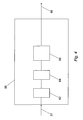
- Fig. 4 is a simplified block diagram of the crankshaft motion processing means 38 from Fig. 2.
- the function block 38 comprises a first and second differentiator 62, 64 and a filter, more particularly a low-pass filter 66.
- the signal behind the second differentiator 64 is thus effectively the second derivative of injection speed 37.
- the filter 66 basically functions as a smoothing means for smoothing the signal prior to outputting it as the misfire rate 40 to the control unit 42 or, more specifically, to the misfire rate calculation means 54.
- the control scheme involves observing the injection speed 37 being indicative of misfires.
- the injection speed 37 functions as an error signal which is to be minimised.
- a maximum EGR rate 44 which is as close as possible to the EGR rate demand 46, which in turn preferably is the optimal EGR rate for NOx reduction etc., is applied to the engine 10.
Landscapes
- Engineering & Computer Science (AREA)
- Chemical & Material Sciences (AREA)
- Combustion & Propulsion (AREA)
- Mechanical Engineering (AREA)
- General Engineering & Computer Science (AREA)
- Combined Controls Of Internal Combustion Engines (AREA)
- Control Of Electric Motors In General (AREA)
- Control Of Motors That Do Not Use Commutators (AREA)
- Control Of Direct Current Motors (AREA)
- Output Control And Ontrol Of Special Type Engine (AREA)
Abstract
Description
- The present invention relates to an engine control method, more particularly to a method for controlling and/or correcting a rate of recirculated exhaust gas without causing combustion instability.
- Exhaust gas recirculation - EGR - is a well-known method to reduce NOx emissions. Current approaches for EGR are based on calibrated EGR rates. That is, the EGR ratio, i.e. the ratio of recirculated exhaust gas to fresh air, is calibrated on the relevant engine at the time of production. High EGR rates can have a negative impact on combustion stability and lead to misfires. Therefore, when calibrating an EGR rate for a certain type of engine, two major constraints apply. Higher EGR rates allow for maximal NOx reduction. However, higher EGR rates increase the possibility of misfires. However, even if an optimal EGR rate, calculated for example on the basis of a mathematical model of the combustion engine, might be available for engine calibration, this optimal value cannot be applied on account of individual engines deviating from the model engine, which for example might be due to production tolerances, ageing or drift effects, with the drift effects, for example, resulting from drift in the intake air (temperature, humidity, etc.) or the combustion. This in turn means that the optimal EGR rate might work for some engines of a relevant engine type, while for other engines or under conditions different from the conditions applied when calculating the optimal EGR rate the same optimal EGR rate might induce undesired misfires or the optimal EGR rate might work for most engines during a certain amount of time while, once the engines are further operated beyond this amount of time, undesired misfires increase. Accordingly, in practice, a suboptimal EGR rate is calibrated to all engines of the same or a sufficiently similar type in order to prevent misfires from occurring.
- It is therefore an object of the present invention to overcome the defects in the prior art, more specifically to allow the engines to be calibrated with an EGR rate as high as possible under the physical constraints involved and at the same time maintain combustion stability.
-
US 6,367,462 discloses a torque management control that coordinates engine throttle, spark and EGR under predefined highly throttled conditions so as to maximize the fuel economy improvement of EGR without degrading engine performance. Under the predefined conditions, EGR is increased to a level that maximises the fuel economy improvement without causing combustion instability, and the throttle position and spark timing are controlled to compensate for the anticipated torque loss while increasing volumetric efficiency and reducing pumping losses. During idle and steady state cruising operation, EGR is increased, and engine throttle position is controlled to regulate the estimated engine output torque in accordance with the driver requested output torque. During transient torque increases, throttle control alone is used to regulate the output torque, while in transient torque decreases, the throttle position is maintained and spark timing is used to regulate the output torque. - The above object of the invention is achieved by carrying out the method having the features defined in
claim 1. The engine control method, more particularly the method for controlling an exhaust gas rate - EGR rate - for an internal combustion engine, according to the invention is characterised in the method comprising the steps of obtaining a value indicative of a combustion stability, hereinafter in short referred to as "misfire rate", and correcting the EGR rate on account of said value, i.e. on account of said "misfire rate". In line with "misfire rate" being used synonymously for "a value indicative of combustion stability", "misfire" or "misfires" in turn will be used synonymously for "decreased combustion stability". - The present invention is particularly concerned with providing a solution which directly links the occurrence of misfire or more specifically, the frequency of occurrence of misfire, basically resulting from excess EGR rate, to the EGR rate, therefore allowing for an EGR rate to be applied to the engine which would result in NOx reductions and misfires being minimised or at least significantly reduced.
- The dependent claims outline advantageous forms of embodiment of the method according to the invention.
- In further accord with the present invention, the misfire rate is obtained by applying a derivative of a rotational speed of a crankshaft of the engine controlled by the method. It has to be understood that observing the rotational speed of the crankshaft is only one method for obtaining a measure indicative of a misfire rate.
- In still further accord with the present invention, the misfire rate is obtained only when a desired EGR rate (EGR demand) exceeds a predetermined EGR demand threshold and/or the engine is operated in quasi steady state conditions. Furthermore, while it is possible to obtain the misfire rate even during transient condition, the misfire rate is preferably only applied when the EGR demand exceeds a predetermined EGR demand threshold and the engine is operated in quasi steady state conditions. This ensures that the method according to the invention is applied only under conditions which have been recognised as providing sufficiently manageable circumstances and effects.
- Advantageously, said quasi steady state operation is recognised by torque changes of the engine, during a predetermined time interval, not exceeding a predetermined torque threshold.
- Further advantageously, said correction of the EGR rate on account of said misfire rate is obtained by applying a misfire gain derived from said misfire rate, wherein said misfire gain is arithmetically combined, more particularly multiplicatively combined, with said EGR demand, and wherein said misfire gain is set to a neutral value, such as "1.0" for multiplicative combination, on account of said EGR demand not exceeding said predetermined EGR demand threshold or on account of the engine not operating in quasi steady state conditions.
- It is a further object of the invention to provide an apparatus capable of solving the above identified problem. This is achieved by an apparatus comprising means for performing the above described steps.
- In accordance with the invention these means for performing the method steps comprise a sensor, preferably a motion sensor or acceleration sensor, associated to a crankshaft of the engine controlled by the apparatus, provided as a means for obtaining a value representative of the crankshaft rotation and/or the crankshaft acceleration.
- In further accordance with the invention said means comprise at least one differentiator, more particularly said at least one differentiator and a filter, more particularly a low-pass filter, provided for obtaining the misfire rate by applying a derivative of a rotational speed of the crankshaft of the engine.
- In still further accordance with the invention said means comprise threshold means, provided for asserting if an EGR demand exceeds a predetermined EGR demand threshold and/or if torque changes of the engine during a predetermined time interval exceed a predetermined torque threshold. An output of these threshold means, preferably logically combined, for example combined by means of an AND-Gate, beneficially functions as a trigger for applying the correction of the EGR rate on account of the misfire rate detected, i.e. as a trigger for applying the control scheme of the invention to the engine control.
- The invention also encompasses the implementation of the invention as a computer program with the appropriate computer readable program code for implementing the method steps described above and a respective computer program product, such as a storage medium, comprising said computer program or computer readable program code.
- Other features and advantages of the present invention will be apparent from the following description of a preferred embodiment of the invention, given as a non-limiting example, illustrated in the drawings. All the elements which are not required for the immediate understanding of the invention are omitted. In the drawings, the same elements are provided with the same reference numerals in the various figures, and in which:
- Fig. 1
- is a simplified block diagram of a combustion engine,
- Fig. 2
- is a simplified block diagram of an apparatus capable of performing the method according to the invention,
- Fig. 3
- is a graph of measured values when applying the invention, and
- Fig. 4
- is a simplified block diagram of a function block from Fig. 2
- In the following description, for purposes of explanation and not limitation, specific details are set forth, such as particular embodiments, data flows, signalling implementations, interfaces, techniques, etc. in order to provide a thorough understanding of the present invention. However, it will be apparent to one skilled in the art that the present invention may be practised in other embodiments that depart from these specific details. For example, while the present invention is sometimes described in the context and terminology of petrol-operated engines, those skilled in the art will appreciate that the present invention can be implemented in any combustion engines, including diesel engines.
- In other instances, detailed descriptions of well-known methods, interfaces, devices, and signalling techniques are omitted so as not to obscure the description of the present invention with unnecessary detail. Moreover, individual function blocks are shown in some of the figures. Those skilled in the art will appreciate that the functions may be implemented using individual hardware circuits, using software functioning in conjunction with a suitably programmed digital microprocessor or general purpose computer, using an application specific integrated circuit (ASIC), and/or using one or more digital signal processors (DSPs).
- Fig. 1 is a simplified block diagram of a
combustion engine 10, where a motor block 12 comprises a number ofcylinders 14 and acrank shaft 16. Upstream of the motor block 12 is anintake manifold 18, athrottle 20, afresh air cooler 22, and anair filter 24 functioning asfresh air intake 26. Downstream of the motor block 12 is anexhaust manifold 28 and anexhaust line 30. - At least part of the exhaust gas leaving the
engine 10 through theexhaust manifold 28 is recirculated from the exhaust manifold via anEGR valve 32, and more specifically via anEGR valve 32 and anEGR cooler 34, to theintake manifold 18 and from there back into theengine 10. - The invention now provides for a solution allowing to feed back a maximum amount of exhaust gas while at the same time maintaining combustion stability. To this end a
crankshaft motion sensor 36 is provided and associated with thecrankshaft 16 for detecting a crankshaft motion, such as crankshaft angle, crankshaft rotation or crankshaft acceleration, etc. The output of thecrankshaft motion sensor 36 is indicative of aninjection speed 37. Thecrankshaft motion sensor 36 is connected to a crankshaft motion processing means 38, theinjection speed 37 being an input to the crankshaft motion processing means 38 and anoutput 40 of the crankshaft motion processing means 38 is fed to acontrol unit 42. - The crankshaft motion processing means 38, while shown as a separate unit, could also be implemented as an integral part of the
control unit 42, and more particularly implemented with the relevant functionality included in the functionality of thecontrol unit 42 when implemented in software or similar. - Depending on the processing of the output of the
crankshaft motion sensor 36, i.e. theinjection speed 37, in the processing means 38 theoutput 40 preferably is a derivative of a rotational speed of thecrankshaft 16, more particularly the second derivative of the rotational speed of thecrankshaft 16. It has been found that misfires lead to changes in the rotation of thecrankshaft 16. More specifically, upon the occurrence of misfires the rotational speed and thus the acceleration of thecrankshaft 16 changes. Thus the characteristics of theinjection speed 37, i.e. a proportion of the rotational speed or the acceleration of thecrankshaft 16, is indicative of misfires. It has further been found that applying the second derivative of the rotational speed of thecrankshaft 16 is the preferred characteristic when detecting misfires. Crankshaft motion processing means 38 are therefore to be understood as comprising means, such as differentiator means (not shown in Fig. 1; cf. Fig. 4), for obtaining a derivative of the rotational speed of thecrankshaft 16, more specifically for obtaining the second derivative of the rotational speed of thecrankshaft 16. To this end the motion processing means 38 are to be understood as comprising two successive differentiator means (Fig. 4: 62, 64). -
Output 40 and the relevant signal or data transmitted to thecontrol unit 42, i.e. data indicative of misfires or amisfire rate 40, are denoted by the same reference numerals. - An
output 44 of thecontrol unit 42, where thecontrol unit 42 may be comprised in the motor electronic or implemented as part of the motor electronic, is used for applying anEGR rate 44 to theEGR valve 32.Output 44 and the relevant signal or data transmitted to theEGR valve 32, i.e. theEGR rate 44, are therefore also denoted by the same reference numerals. - Since the
EGR rate 44 is effectively an output ofcontrol unit 42, theEGR rate 44 more specifically is a correctedEGR rate 44, where the correction has been performed on account of saidmisfire rate 40. - While the
output 40 is indicative of misfires, the invention, according to a further aspect, provides for themisfire rate 40 only being obtained, or theEGR rate 44 only being corrected, i.e. the position of theEGR valve 32 only being affected, once a desired EGR rate (EGR demand) 46 exceeds a predeterminedEGR demand threshold 48 and/or the engine is operated in quasi steady state conditions. - The
EGR demand 46 is fed to thecontrol unit 42 via a furtherrelevant input 46. Theoutput 44, i.e. theEGR rate 44, is based on theEGR demand 46. More specifically theEGR rate 44 is a result of a mathematical combination, where theEGR demand 46 and themisfire rate 40, i.e. theoutput 40 or a proportion of theoutput 40, apply as factors. Furthermore, theEGR demand threshold 48 is a predefined or predetermined value also available in thecontrol unit 42, for example by means of afurther input 48. Thecontrol unit 42 comprise means for comparing theEGR demand 46 and the EGR demand threshold. An example of said means is a comparator (not shown). Thus, whether or not theEGR demand 46 exceeds the predeterminedEGR demand threshold 48 is available in thecontrol unit 42 by evaluating the output of such a comparator. - Whether or not the
engine 10 operates in a quasi steady state condition is recognised by torque changes of theengine 10 not exceeding a predetermined torque threshold, more particularly by torque changes of theengine 10, during a predetermined time interval, not exceeding the torque threshold. - Torque changes can be detected by driver torque demand, where driver torque demands would be derivable amongst others for example from the position of the accelerator pedal. On the other hand, a value representative of the torque demand can be expected to be available in the engine control unit. Therefore, a
further input 50 for transmitting a signal indicative of the torque demand, derived e.g. from the accelerator pedal position or directly from the engine control unit (not shown), is fed to thecontrol unit 42. - Analysing a signal, such as the characteristics of
input 50 during a predetermined time interval and checking whether or not that signal during the time interval exceeds a predetermined threshold, such as the aforementioned predetermined torque threshold, is a well-known matter in the art and is readily available by implementing the relevant means, more specifically by implementing the relevant programme code e.g. program code for detecting the relevant time interval and for comparing two values, into thecontrol unit 42. A value representative of the duration of the time interval and another value representative of the relevant torque threshold could be fed to thecontrol unit 42 by means of further inputs (not shown in Fig. 1; cf. Fig. 2). The time interval and/or the torque threshold could also be stored in digital form in thecontrol unit 42. - Fig. 2 is a simplified block diagram of the
control unit 42 and some of the functionality comprised therein. According to what is described above,output 44 is anEGR rate 44 for controlling the position ofEGR valve 32. TheEGR rate 44 is obtained on the basis of anEGR demand 46 provided as an input to thecontrol unit 42. Furthermore, theEGR rate 44 is influenced by amisfire rate 40, more specifically amisfire gain 52 derived from themisfire rate 40 through a misfire rate calculation means 54 implemented within thecontrol unit 42. - On the basis of the
EGR demand 46 and themisfire gain 52, theEGR rate 44 is obtained by means of an EGR rate calculation means 56 on the basis of a mathematical combination of at least theaforementioned parameters parameters - On the basis of
further output 50 of thecrankshaft motion sensor 36, and more specifically of the crankshaft motion processing means 38, the misfire rate calculation means 54 analyses whether or not theengine 10 is operated in a quasi steady state condition. As aforementioned, quasi steady state conditions are found to be present once torque changes of theengine 10 during a predetermined time interval do not exceed a predetermined threshold value. A representation of said predetermined torque threshold is provided as afurther input 58 to the misfire rate calculation means 54. Furthermore, a representation of said predetermined time interval, during which torque changes are observed, is provided as a stillfurther input 60 to the misfire rate calculation means 54. On the basis ofinputs engine 10 is operated in quasi steady state conditions and further able to output themisfire gain 52 on account of whether or not theengine 10 is operated in quasi steady state conditions. This, for example, is achieved by providing the processedinput 40 or a proportion of processedinput 40 asoutput 52 onceinputs inputs - Fig. 3 is a graph of the
injection speed 37,misfire rate 40 and themisfire gain 52. The abscissa is a time axis. The right hand ordinate refers to revolutions per minute (RPM) of theengine 10. The left hand ordinate is scaled from "0.0" to "1.2" to allow for themisfire gain 52, which is a multiplier, usually of a value close to "1.0", to be displayed in the same coordinate system. - Misfires are present when oscillations are seen on the
injection speed graph 37.Graphs misfire rate graph 40 is higher the more noise, i.e. oscillations, are present on theinjection speed graph 37. - As would be apparent from Fig. 3 the misfire gain preferably is a value close to "1.0", where "1.0" effectively is a "neutral value" resulting in a proportion of the
EGR demand 46, suitable for and provided to actuate theEGR valve 32, being applied to saidEGR valve 32. However, once misfire occurs, the EGR rate is reduced and an appropriate fraction theEGR demand 46 is applied for actuating theEGR valve 32, where the "appropriate fraction" is the current value of themisfire gain 52 or a proportion of the current value of themisfire gain 52, e.g. a value of "0.9" for themisfire gain 52 would result in "90%" of theEGR demand 46 being applied for actuating theEGR valve 32. - Up to the first vertical line in Fig. 3 the
graphs misfire gain 52 to the neutral value, i.e. "1.0". The neutral value for themisfire gain 52 has the effect that theEGR rate 44 in the EGR rate calculation means 56 is solely calculated on the basis of theEGR demand 46, i.e. theEGR rate 44 equals theEGR demand 46. This, as will be apparent form the relevant section of theinjection speed graph 37, leads to significant changes in the rotational speed of thecrankshaft 16, i.e. significant changes in theinjection speed 37, which in turn is an indicated for decreased combustion stability, e.g. increased of misfires. It has to be understood that the ramp in themisfire gain graph 52 immediately after the first vertical line is an effect of manually deactivating the control scheme. In the section after the second vertical line, the control scheme is applied again and it can be seen that the combustion stability improves soon, since the noise, i.e. high frequent oscillation, on theinjection speed graph 37 is significantly reduced immediately after reactivating the control scheme according to the invention. - Fig. 4 is a simplified block diagram of the crankshaft motion processing means 38 from Fig. 2. According to Fig. 4 the
function block 38 comprises a first andsecond differentiator pass filter 66. The signal behind thesecond differentiator 64 is thus effectively the second derivative ofinjection speed 37. Thefilter 66 basically functions as a smoothing means for smoothing the signal prior to outputting it as themisfire rate 40 to thecontrol unit 42 or, more specifically, to the misfire rate calculation means 54. - Although a preferred embodiment of the invention has been illustrated and described herein, it is recognised that changes and variations may be made without departing from the invention as set forth in the claims. More specifically, while the particular engine control method and the corresponding apparatus as herein shown and described in detail is fully capable of attaining the above-described objects of the invention, it is to be understood that it is the presently preferred embodiment of the invention and thus is representative of the subject matter which is broadly contemplated by the present invention. However, the scope of the present invention fully encompasses other embodiments which may become obvious to those skilled in the art. Accordingly, the scope of the present invention is to be limited by nothing other than the appended claims, in which for example, reference to an element in the singular is not intended to mean "one and only one" unless explicitly so stated, but rather "one or more". All structural and functional equivalents to the elements of the above-described preferred embodiment that are known, or later come to be known, to those of ordinary skill in the art are expressly incorporated herein by reference and are intended to be encompassed by the present claims. Moreover, it is not necessary for a device or method to address each and every problem sought to be solved by the present invention, in order to be regarded as being encompassed by the present claims.
- Summarising the invention described above it can shortly be described as proposing a control scheme allowing at each instance of time maximum EGR to be recirculated without effecting combustion stability. To this end, the control scheme involves observing the
injection speed 37 being indicative of misfires. Thus effectively, the control scheme aims to reduce misfires. In control theory terminology theinjection speed 37 functions as an error signal which is to be minimised. By correcting theEGR rate 44 in accordance with the injection speed 37 amaximum EGR rate 44, which is as close as possible to theEGR rate demand 46, which in turn preferably is the optimal EGR rate for NOx reduction etc., is applied to theengine 10. -
- 10
- combustion engine
- 12
- motor block
- 14
- cylinder
- 16
- crank shaft
- 18
- intake manifold
- 20
- throttle
- 22
- fresh air cooler
- 24
- air filter
- 26
- fresh air intake
- 28
- exhaust manifold
- 30
- exhaust line
- 32
- EGR valve
- 34
- EGR cooler
- 36
- crankshaft motion sensor
- 37
- injection speed
- 38
- crankshaft motion processing means
- 40
- misfire rate
- 42
- control unit
- 44
- EGR rate
- 46
- desired EGR rate/EGR demand
- 48
- EGR demand threshold
- 50
- further output
- 52
- misfire gain
- 54
- misfire rate calculation means
- 56
- EGR rate calculation means
- 58
- input
- 60
- input
- 62
- first differentiator
- 64
- second differentiator
- 66
- filter
Claims (11)
- An engine control method, more particularly, a method for controlling an exhaust gas rate - EGR rate (44) - for an internal combustion engine (10),
characterised in the method comprising the steps of:obtaining a misfire rate (40) andcorrecting an EGR rate (44) on account of said misfire rate (40). - The method of claim 1, wherein
the misfire rate (40) is obtained by applying a derivative of a rotational speed of a crankshaft (16) of the engine (10) controlled by the method. - The method of claim 1 or claim 2, wherein
the misfire rate (40) is obtained once an EGR demand (46) exceeds a predetermined EGR demand threshold (48) and/or the engine (10) is operated in quasi steady state conditions. - The method of claim 3, wherein
said quasi steady state operation is recognised by torque changes of the engine, during a predetermined time interval, not exceeding a predetermined torque threshold. - The method of claim 3 or claim 4, wherein
said correction of the EGR rate (44) on account of said misfire rate (40) is obtained by applying a misfire gain (52) derived from said misfire rate (40),
wherein said misfire gain (52) is arithmetically combined with said EGR demand (46), and
wherein said misfire gain (52) is set to a neutral value on account of said EGR demand (46) not exceeding said predetermined EGR demand threshold (48) or on account of the engine (10) not operating in quasi steady state conditions. - Engine control apparatus, more particularly, apparatus for controlling an exhaust gas rate - EGR rate (44) - for an internal combustion engine,
characterised in
comprising means (36, 38, 42, 54, 56) for performing the steps of the method in any of claims 1 to 5. - The engine control apparatus of claim 6,
wherein said means (36, 38, 42, 54, 56) comprise a sensor (36), associated to a crankshaft (16) of the engine (10) controlled by the apparatus, provided as a means for obtaining a value representative of the crankshaft rotation and/or the crankshaft acceleration. - The engine control apparatus of claim 7,
wherein said means (36, 38, 42, 54, 56) comprise at least one differentiator (62, 64), more particularly said at least one differentiator (62, 64) and a filter (66), more particularly a low-pass filter (66), provided for obtaining the misfire rate (40) by applying a derivative of a rotational speed of the crankshaft (16) of the engine (10). - The engine control apparatus of claim 6, claim 7 or claim 8,
wherein said means (36, 38, 42, 54, 56) comprise threshold means provided for asserting if an EGR demand (46) exceeds a predetermined EGR demand threshold (48) and/or if torque changes of the engine (10) during a predetermined time interval exceed a predetermined torque threshold. - A computer program with a computer readable program code for implementing the method according to one of claims 1 to 5 when the program code is run on a computer.
- A computer program product, such as a storage medium, with a computer readable program code for implementing the method according to any one of claims 1 to 5 when the program code is run on a computer.
Priority Applications (3)
| Application Number | Priority Date | Filing Date | Title |
|---|---|---|---|
| AT05017539T ATE413525T1 (en) | 2005-08-11 | 2005-08-11 | METHOD AND DEVICE FOR CONTROLLING A MOTOR |
| DE602005010856T DE602005010856D1 (en) | 2005-08-11 | 2005-08-11 | Method and device for controlling a motor |
| EP05017539A EP1752641B1 (en) | 2005-08-11 | 2005-08-11 | Engine control method and apparatus capable of performing said method |
Applications Claiming Priority (1)
| Application Number | Priority Date | Filing Date | Title |
|---|---|---|---|
| EP05017539A EP1752641B1 (en) | 2005-08-11 | 2005-08-11 | Engine control method and apparatus capable of performing said method |
Publications (2)
| Publication Number | Publication Date |
|---|---|
| EP1752641A1 true EP1752641A1 (en) | 2007-02-14 |
| EP1752641B1 EP1752641B1 (en) | 2008-11-05 |
Family
ID=35457040
Family Applications (1)
| Application Number | Title | Priority Date | Filing Date |
|---|---|---|---|
| EP05017539A Expired - Lifetime EP1752641B1 (en) | 2005-08-11 | 2005-08-11 | Engine control method and apparatus capable of performing said method |
Country Status (3)
| Country | Link |
|---|---|
| EP (1) | EP1752641B1 (en) |
| AT (1) | ATE413525T1 (en) |
| DE (1) | DE602005010856D1 (en) |
Cited By (2)
| Publication number | Priority date | Publication date | Assignee | Title |
|---|---|---|---|---|
| CN103732887A (en) * | 2011-08-03 | 2014-04-16 | 丰田自动车株式会社 | Control apparatus for internal combustion engine and method therefor |
| CN115559822A (en) * | 2022-09-27 | 2023-01-03 | 东风汽车集团股份有限公司 | Method for controlling target EGR rate |
Citations (7)
| Publication number | Priority date | Publication date | Assignee | Title |
|---|---|---|---|---|
| US3872846A (en) * | 1972-04-24 | 1975-03-25 | Bendix Corp | Exhaust gas recirculation (EGR) internal combustion engine roughness control system |
| US4186701A (en) * | 1976-08-23 | 1980-02-05 | Nissan Motor Company Limited | Feedback control of exhaust gas recirculation based on combustion condition |
| EP0829633A1 (en) * | 1996-03-08 | 1998-03-18 | Mitsubishi Jidosha Kogyo Kabushiki Kaisha | Device for controlling cylinder fuel injection type internal combustion engine |
| US5806014A (en) * | 1995-05-01 | 1998-09-08 | Motorola Inc. | Combustion control of an internal combustion engine proximate an extinction limit |
| DE19727793A1 (en) * | 1997-06-30 | 1999-01-07 | Siemens Ag | Combustion engine control method |
| FR2798963A1 (en) * | 1999-09-29 | 2001-03-30 | Siemens Ag | METHOD FOR CONTROLLING AN INTERNAL COMBUSTION ENGINE EQUIPPED WITH A DEVICE FOR RECYCLING EXHAUST GASES, AND OPERATING WITH A LAMINATED LOAD |
| US6367462B1 (en) | 2000-09-13 | 2002-04-09 | Delphi Technologies, Inc. | Engine torque management method with high dilution EGR control |
-
2005
- 2005-08-11 EP EP05017539A patent/EP1752641B1/en not_active Expired - Lifetime
- 2005-08-11 DE DE602005010856T patent/DE602005010856D1/en not_active Expired - Lifetime
- 2005-08-11 AT AT05017539T patent/ATE413525T1/en not_active IP Right Cessation
Patent Citations (7)
| Publication number | Priority date | Publication date | Assignee | Title |
|---|---|---|---|---|
| US3872846A (en) * | 1972-04-24 | 1975-03-25 | Bendix Corp | Exhaust gas recirculation (EGR) internal combustion engine roughness control system |
| US4186701A (en) * | 1976-08-23 | 1980-02-05 | Nissan Motor Company Limited | Feedback control of exhaust gas recirculation based on combustion condition |
| US5806014A (en) * | 1995-05-01 | 1998-09-08 | Motorola Inc. | Combustion control of an internal combustion engine proximate an extinction limit |
| EP0829633A1 (en) * | 1996-03-08 | 1998-03-18 | Mitsubishi Jidosha Kogyo Kabushiki Kaisha | Device for controlling cylinder fuel injection type internal combustion engine |
| DE19727793A1 (en) * | 1997-06-30 | 1999-01-07 | Siemens Ag | Combustion engine control method |
| FR2798963A1 (en) * | 1999-09-29 | 2001-03-30 | Siemens Ag | METHOD FOR CONTROLLING AN INTERNAL COMBUSTION ENGINE EQUIPPED WITH A DEVICE FOR RECYCLING EXHAUST GASES, AND OPERATING WITH A LAMINATED LOAD |
| US6367462B1 (en) | 2000-09-13 | 2002-04-09 | Delphi Technologies, Inc. | Engine torque management method with high dilution EGR control |
Cited By (3)
| Publication number | Priority date | Publication date | Assignee | Title |
|---|---|---|---|---|
| CN103732887A (en) * | 2011-08-03 | 2014-04-16 | 丰田自动车株式会社 | Control apparatus for internal combustion engine and method therefor |
| CN103732887B (en) * | 2011-08-03 | 2016-07-06 | 丰田自动车株式会社 | Control equipment and control method for internal combustion engine |
| CN115559822A (en) * | 2022-09-27 | 2023-01-03 | 东风汽车集团股份有限公司 | Method for controlling target EGR rate |
Also Published As
| Publication number | Publication date |
|---|---|
| EP1752641B1 (en) | 2008-11-05 |
| ATE413525T1 (en) | 2008-11-15 |
| DE602005010856D1 (en) | 2008-12-18 |
Similar Documents
| Publication | Publication Date | Title |
|---|---|---|
| JP6245221B2 (en) | Control device for internal combustion engine | |
| US7272486B2 (en) | Method of controlling an internal combustion engine with a common rail fuel injection system | |
| EP2532867A2 (en) | An exhaust gas recirculation system for an internal combustion engine | |
| CN104420979A (en) | Method of operating an internal combustion engine with a turbocharger and control device | |
| EP2574762A1 (en) | Soot emission estimation method and arrangement | |
| CN106605055B (en) | Method and apparatus for actuating an exhaust gas recirculation valve of a supercharged internal combustion engine with exhaust gas recirculation | |
| JP2009281143A (en) | Fuel control for internal combustion engine | |
| JP4861915B2 (en) | Control device for internal combustion engine | |
| US8170776B2 (en) | Method and device for controlling an internal combustion engine | |
| KR102692489B1 (en) | Control method of engine combustion for decreasing irregular vibration | |
| JP5387914B2 (en) | In-cylinder inflow EGR gas flow rate estimation device for internal combustion engine | |
| CN105422294B (en) | Method for identifying and interpreting transient driving conditions | |
| WO2014080523A1 (en) | Control device of internal combustion engine | |
| EP1752641B1 (en) | Engine control method and apparatus capable of performing said method | |
| JP2018044462A (en) | Turbo rotation speed control device and turbo rotation speed control method | |
| CN113006953B (en) | Gas amount control method and system for improving oil injection performance | |
| JP2004019629A (en) | Control device for internal combustion engine | |
| JP2007278223A (en) | In-cylinder injection type spark ignition internal combustion engine control device | |
| JP2006090204A (en) | Intake flow control device for internal combustion engine | |
| JP2015190397A (en) | Soot emission estimation device for internal combustion engine | |
| JP2010025126A (en) | Method for detecting engine air volume | |
| JP4382851B2 (en) | Control method and control apparatus for internal combustion engine | |
| JP2002047994A (en) | Knock control system of internal combustion engine | |
| CN114962042A (en) | Method for controlling mixed injection of fuel in an engine, device and vehicle therefor | |
| JP2016200034A (en) | Control device for internal combustion engine |
Legal Events
| Date | Code | Title | Description |
|---|---|---|---|
| PUAI | Public reference made under article 153(3) epc to a published international application that has entered the european phase |
Free format text: ORIGINAL CODE: 0009012 |
|
| 17P | Request for examination filed |
Effective date: 20060324 |
|
| AK | Designated contracting states |
Kind code of ref document: A1 Designated state(s): AT BE BG CH CY CZ DE DK EE ES FI FR GB GR HU IE IS IT LI LT LU LV MC NL PL PT RO SE SI SK TR |
|
| AX | Request for extension of the european patent |
Extension state: AL BA HR MK YU |
|
| RTI1 | Title (correction) |
Free format text: ENGINE CONTROL METHOD AND APPARATUS CAPABLE OF PERFORMING SAID METHOD |
|
| AKX | Designation fees paid |
Designated state(s): AT BE BG CH CY CZ DE DK EE ES FI FR GB GR HU IE IS IT LI LT LU LV MC NL PL PT RO SE SI SK TR |
|
| GRAP | Despatch of communication of intention to grant a patent |
Free format text: ORIGINAL CODE: EPIDOSNIGR1 |
|
| GRAS | Grant fee paid |
Free format text: ORIGINAL CODE: EPIDOSNIGR3 |
|
| GRAA | (expected) grant |
Free format text: ORIGINAL CODE: 0009210 |
|
| AK | Designated contracting states |
Kind code of ref document: B1 Designated state(s): AT BE BG CH CY CZ DE DK EE ES FI FR GB GR HU IE IS IT LI LT LU LV MC NL PL PT RO SE SI SK TR |
|
| REG | Reference to a national code |
Ref country code: GB Ref legal event code: FG4D |
|
| REG | Reference to a national code |
Ref country code: CH Ref legal event code: EP |
|
| REG | Reference to a national code |
Ref country code: IE Ref legal event code: FG4D |
|
| REF | Corresponds to: |
Ref document number: 602005010856 Country of ref document: DE Date of ref document: 20081218 Kind code of ref document: P |
|
| NLV1 | Nl: lapsed or annulled due to failure to fulfill the requirements of art. 29p and 29m of the patents act | ||
| LTIE | Lt: invalidation of european patent or patent extension |
Effective date: 20081105 |
|
| PG25 | Lapsed in a contracting state [announced via postgrant information from national office to epo] |
Ref country code: ES Free format text: LAPSE BECAUSE OF FAILURE TO SUBMIT A TRANSLATION OF THE DESCRIPTION OR TO PAY THE FEE WITHIN THE PRESCRIBED TIME-LIMIT Effective date: 20090216 Ref country code: LT Free format text: LAPSE BECAUSE OF FAILURE TO SUBMIT A TRANSLATION OF THE DESCRIPTION OR TO PAY THE FEE WITHIN THE PRESCRIBED TIME-LIMIT Effective date: 20081105 Ref country code: AT Free format text: LAPSE BECAUSE OF FAILURE TO SUBMIT A TRANSLATION OF THE DESCRIPTION OR TO PAY THE FEE WITHIN THE PRESCRIBED TIME-LIMIT Effective date: 20081105 |
|
| PG25 | Lapsed in a contracting state [announced via postgrant information from national office to epo] |
Ref country code: SI Free format text: LAPSE BECAUSE OF FAILURE TO SUBMIT A TRANSLATION OF THE DESCRIPTION OR TO PAY THE FEE WITHIN THE PRESCRIBED TIME-LIMIT Effective date: 20081105 Ref country code: PL Free format text: LAPSE BECAUSE OF FAILURE TO SUBMIT A TRANSLATION OF THE DESCRIPTION OR TO PAY THE FEE WITHIN THE PRESCRIBED TIME-LIMIT Effective date: 20081105 Ref country code: NL Free format text: LAPSE BECAUSE OF FAILURE TO SUBMIT A TRANSLATION OF THE DESCRIPTION OR TO PAY THE FEE WITHIN THE PRESCRIBED TIME-LIMIT Effective date: 20081105 Ref country code: FI Free format text: LAPSE BECAUSE OF FAILURE TO SUBMIT A TRANSLATION OF THE DESCRIPTION OR TO PAY THE FEE WITHIN THE PRESCRIBED TIME-LIMIT Effective date: 20081105 Ref country code: IS Free format text: LAPSE BECAUSE OF FAILURE TO SUBMIT A TRANSLATION OF THE DESCRIPTION OR TO PAY THE FEE WITHIN THE PRESCRIBED TIME-LIMIT Effective date: 20090305 Ref country code: LV Free format text: LAPSE BECAUSE OF FAILURE TO SUBMIT A TRANSLATION OF THE DESCRIPTION OR TO PAY THE FEE WITHIN THE PRESCRIBED TIME-LIMIT Effective date: 20081105 |
|
| PG25 | Lapsed in a contracting state [announced via postgrant information from national office to epo] |
Ref country code: BG Free format text: LAPSE BECAUSE OF FAILURE TO SUBMIT A TRANSLATION OF THE DESCRIPTION OR TO PAY THE FEE WITHIN THE PRESCRIBED TIME-LIMIT Effective date: 20090205 Ref country code: DK Free format text: LAPSE BECAUSE OF FAILURE TO SUBMIT A TRANSLATION OF THE DESCRIPTION OR TO PAY THE FEE WITHIN THE PRESCRIBED TIME-LIMIT Effective date: 20081105 Ref country code: BE Free format text: LAPSE BECAUSE OF FAILURE TO SUBMIT A TRANSLATION OF THE DESCRIPTION OR TO PAY THE FEE WITHIN THE PRESCRIBED TIME-LIMIT Effective date: 20081105 Ref country code: EE Free format text: LAPSE BECAUSE OF FAILURE TO SUBMIT A TRANSLATION OF THE DESCRIPTION OR TO PAY THE FEE WITHIN THE PRESCRIBED TIME-LIMIT Effective date: 20081105 Ref country code: RO Free format text: LAPSE BECAUSE OF FAILURE TO SUBMIT A TRANSLATION OF THE DESCRIPTION OR TO PAY THE FEE WITHIN THE PRESCRIBED TIME-LIMIT Effective date: 20081105 |
|
| PG25 | Lapsed in a contracting state [announced via postgrant information from national office to epo] |
Ref country code: CZ Free format text: LAPSE BECAUSE OF FAILURE TO SUBMIT A TRANSLATION OF THE DESCRIPTION OR TO PAY THE FEE WITHIN THE PRESCRIBED TIME-LIMIT Effective date: 20081105 Ref country code: SE Free format text: LAPSE BECAUSE OF FAILURE TO SUBMIT A TRANSLATION OF THE DESCRIPTION OR TO PAY THE FEE WITHIN THE PRESCRIBED TIME-LIMIT Effective date: 20090205 Ref country code: PT Free format text: LAPSE BECAUSE OF FAILURE TO SUBMIT A TRANSLATION OF THE DESCRIPTION OR TO PAY THE FEE WITHIN THE PRESCRIBED TIME-LIMIT Effective date: 20090406 |
|
| PLBE | No opposition filed within time limit |
Free format text: ORIGINAL CODE: 0009261 |
|
| STAA | Information on the status of an ep patent application or granted ep patent |
Free format text: STATUS: NO OPPOSITION FILED WITHIN TIME LIMIT |
|
| PG25 | Lapsed in a contracting state [announced via postgrant information from national office to epo] |
Ref country code: SK Free format text: LAPSE BECAUSE OF FAILURE TO SUBMIT A TRANSLATION OF THE DESCRIPTION OR TO PAY THE FEE WITHIN THE PRESCRIBED TIME-LIMIT Effective date: 20081105 |
|
| 26N | No opposition filed |
Effective date: 20090806 |
|
| PG25 | Lapsed in a contracting state [announced via postgrant information from national office to epo] |
Ref country code: MC Free format text: LAPSE BECAUSE OF NON-PAYMENT OF DUE FEES Effective date: 20090831 |
|
| REG | Reference to a national code |
Ref country code: CH Ref legal event code: PL |
|
| PG25 | Lapsed in a contracting state [announced via postgrant information from national office to epo] |
Ref country code: CH Free format text: LAPSE BECAUSE OF NON-PAYMENT OF DUE FEES Effective date: 20090831 Ref country code: LI Free format text: LAPSE BECAUSE OF NON-PAYMENT OF DUE FEES Effective date: 20090831 |
|
| REG | Reference to a national code |
Ref country code: IE Ref legal event code: MM4A |
|
| PG25 | Lapsed in a contracting state [announced via postgrant information from national office to epo] |
Ref country code: IE Free format text: LAPSE BECAUSE OF NON-PAYMENT OF DUE FEES Effective date: 20090811 |
|
| PG25 | Lapsed in a contracting state [announced via postgrant information from national office to epo] |
Ref country code: GR Free format text: LAPSE BECAUSE OF FAILURE TO SUBMIT A TRANSLATION OF THE DESCRIPTION OR TO PAY THE FEE WITHIN THE PRESCRIBED TIME-LIMIT Effective date: 20090206 |
|
| PG25 | Lapsed in a contracting state [announced via postgrant information from national office to epo] |
Ref country code: IT Free format text: LAPSE BECAUSE OF FAILURE TO SUBMIT A TRANSLATION OF THE DESCRIPTION OR TO PAY THE FEE WITHIN THE PRESCRIBED TIME-LIMIT Effective date: 20081105 |
|
| REG | Reference to a national code |
Ref country code: FR Ref legal event code: TP |
|
| PG25 | Lapsed in a contracting state [announced via postgrant information from national office to epo] |
Ref country code: LU Free format text: LAPSE BECAUSE OF NON-PAYMENT OF DUE FEES Effective date: 20090811 |
|
| PG25 | Lapsed in a contracting state [announced via postgrant information from national office to epo] |
Ref country code: HU Free format text: LAPSE BECAUSE OF FAILURE TO SUBMIT A TRANSLATION OF THE DESCRIPTION OR TO PAY THE FEE WITHIN THE PRESCRIBED TIME-LIMIT Effective date: 20090506 |
|
| PG25 | Lapsed in a contracting state [announced via postgrant information from national office to epo] |
Ref country code: TR Free format text: LAPSE BECAUSE OF FAILURE TO SUBMIT A TRANSLATION OF THE DESCRIPTION OR TO PAY THE FEE WITHIN THE PRESCRIBED TIME-LIMIT Effective date: 20081105 |
|
| PG25 | Lapsed in a contracting state [announced via postgrant information from national office to epo] |
Ref country code: CY Free format text: LAPSE BECAUSE OF FAILURE TO SUBMIT A TRANSLATION OF THE DESCRIPTION OR TO PAY THE FEE WITHIN THE PRESCRIBED TIME-LIMIT Effective date: 20081105 |
|
| REG | Reference to a national code |
Ref country code: GB Ref legal event code: 732E Free format text: REGISTERED BETWEEN 20130425 AND 20130501 |
|
| REG | Reference to a national code |
Ref country code: GB Ref legal event code: 732E Free format text: REGISTERED BETWEEN 20140220 AND 20140226 |
|
| REG | Reference to a national code |
Ref country code: FR Ref legal event code: TP Owner name: DELPHI INTERNATIONAL OPERATIONS LUXEMBOURG S.A, LU Effective date: 20140516 |
|
| REG | Reference to a national code |
Ref country code: DE Ref legal event code: R082 Ref document number: 602005010856 Country of ref document: DE Representative=s name: MANITZ, FINSTERWALD & PARTNER GBR, DE |
|
| REG | Reference to a national code |
Ref country code: DE Ref legal event code: R081 Ref document number: 602005010856 Country of ref document: DE Owner name: DELPHI INTERNATIONAL OPERATIONS LUXEMBOURG S.A, LU Free format text: FORMER OWNER: DELPHI TECHNOLOGIES HOLDING S.A.R.L., BASCHARAGE, LU Effective date: 20140702 Ref country code: DE Ref legal event code: R082 Ref document number: 602005010856 Country of ref document: DE Representative=s name: MANITZ, FINSTERWALD & PARTNER GBR, DE Effective date: 20140702 Ref country code: DE Ref legal event code: R082 Ref document number: 602005010856 Country of ref document: DE Representative=s name: MANITZ FINSTERWALD PATENTANWAELTE PARTMBB, DE Effective date: 20140702 |
|
| REG | Reference to a national code |
Ref country code: FR Ref legal event code: PLFP Year of fee payment: 11 |
|
| REG | Reference to a national code |
Ref country code: FR Ref legal event code: PLFP Year of fee payment: 12 |
|
| REG | Reference to a national code |
Ref country code: FR Ref legal event code: PLFP Year of fee payment: 13 |
|
| REG | Reference to a national code |
Ref country code: FR Ref legal event code: PLFP Year of fee payment: 14 |
|
| REG | Reference to a national code |
Ref country code: DE Ref legal event code: R082 Ref document number: 602005010856 Country of ref document: DE Representative=s name: MANITZ FINSTERWALD PATENT- UND RECHTSANWALTSPA, DE Ref country code: DE Ref legal event code: R081 Ref document number: 602005010856 Country of ref document: DE Owner name: DELPHI AUTOMOTIVE SYSTEMS LUXEMBOURG S.A., LU Free format text: FORMER OWNER: DELPHI INTERNATIONAL OPERATIONS LUXEMBOURG S.A R.L., BASCHARAGE, LU |
|
| REG | Reference to a national code |
Ref country code: GB Ref legal event code: 732E Free format text: REGISTERED BETWEEN 20190222 AND 20190227 |
|
| P01 | Opt-out of the competence of the unified patent court (upc) registered |
Effective date: 20230327 |
|
| REG | Reference to a national code |
Ref country code: GB Ref legal event code: 732E Free format text: REGISTERED BETWEEN 20240718 AND 20240724 |
|
| PGFP | Annual fee paid to national office [announced via postgrant information from national office to epo] |
Ref country code: DE Payment date: 20240709 Year of fee payment: 20 |
|
| PGFP | Annual fee paid to national office [announced via postgrant information from national office to epo] |
Ref country code: GB Payment date: 20240711 Year of fee payment: 20 |
|
| PGFP | Annual fee paid to national office [announced via postgrant information from national office to epo] |
Ref country code: FR Payment date: 20240710 Year of fee payment: 20 |
|
| REG | Reference to a national code |
Ref country code: DE Ref legal event code: R081 Ref document number: 602005010856 Country of ref document: DE Owner name: PHINIA DELPHI LUXEMBOURG SARL, LU Free format text: FORMER OWNER: DELPHI AUTOMOTIVE SYSTEMS LUXEMBOURG S.A., BASCHARAGE, LU |
|
| REG | Reference to a national code |
Ref country code: DE Ref legal event code: R071 Ref document number: 602005010856 Country of ref document: DE |
|
| REG | Reference to a national code |
Ref country code: GB Ref legal event code: PE20 Expiry date: 20250810 |