EP1752330A2 - Vehicle drive power distribution - Google Patents
Vehicle drive power distribution Download PDFInfo
- Publication number
- EP1752330A2 EP1752330A2 EP06253977A EP06253977A EP1752330A2 EP 1752330 A2 EP1752330 A2 EP 1752330A2 EP 06253977 A EP06253977 A EP 06253977A EP 06253977 A EP06253977 A EP 06253977A EP 1752330 A2 EP1752330 A2 EP 1752330A2
- Authority
- EP
- European Patent Office
- Prior art keywords
- clutch
- transfer
- motive power
- wheels
- speed
- Prior art date
- Legal status (The legal status is an assumption and is not a legal conclusion. Google has not performed a legal analysis and makes no representation as to the accuracy of the status listed.)
- Granted
Links
Images

Classifications
-
- B—PERFORMING OPERATIONS; TRANSPORTING
- B60—VEHICLES IN GENERAL
- B60K—ARRANGEMENT OR MOUNTING OF PROPULSION UNITS OR OF TRANSMISSIONS IN VEHICLES; ARRANGEMENT OR MOUNTING OF PLURAL DIVERSE PRIME-MOVERS IN VEHICLES; AUXILIARY DRIVES FOR VEHICLES; INSTRUMENTATION OR DASHBOARDS FOR VEHICLES; ARRANGEMENTS IN CONNECTION WITH COOLING, AIR INTAKE, GAS EXHAUST OR FUEL SUPPLY OF PROPULSION UNITS IN VEHICLES
- B60K23/00—Arrangement or mounting of control devices for vehicle transmissions, or parts thereof, not otherwise provided for
- B60K23/04—Arrangement or mounting of control devices for vehicle transmissions, or parts thereof, not otherwise provided for for differential gearing
-
- B—PERFORMING OPERATIONS; TRANSPORTING
- B60—VEHICLES IN GENERAL
- B60K—ARRANGEMENT OR MOUNTING OF PROPULSION UNITS OR OF TRANSMISSIONS IN VEHICLES; ARRANGEMENT OR MOUNTING OF PLURAL DIVERSE PRIME-MOVERS IN VEHICLES; AUXILIARY DRIVES FOR VEHICLES; INSTRUMENTATION OR DASHBOARDS FOR VEHICLES; ARRANGEMENTS IN CONNECTION WITH COOLING, AIR INTAKE, GAS EXHAUST OR FUEL SUPPLY OF PROPULSION UNITS IN VEHICLES
- B60K17/00—Arrangement or mounting of transmissions in vehicles
- B60K17/34—Arrangement or mounting of transmissions in vehicles for driving both front and rear wheels, e.g. four wheel drive vehicles
- B60K17/344—Arrangement or mounting of transmissions in vehicles for driving both front and rear wheels, e.g. four wheel drive vehicles having a transfer gear
-
- B—PERFORMING OPERATIONS; TRANSPORTING
- B60—VEHICLES IN GENERAL
- B60K—ARRANGEMENT OR MOUNTING OF PROPULSION UNITS OR OF TRANSMISSIONS IN VEHICLES; ARRANGEMENT OR MOUNTING OF PLURAL DIVERSE PRIME-MOVERS IN VEHICLES; AUXILIARY DRIVES FOR VEHICLES; INSTRUMENTATION OR DASHBOARDS FOR VEHICLES; ARRANGEMENTS IN CONNECTION WITH COOLING, AIR INTAKE, GAS EXHAUST OR FUEL SUPPLY OF PROPULSION UNITS IN VEHICLES
- B60K23/00—Arrangement or mounting of control devices for vehicle transmissions, or parts thereof, not otherwise provided for
- B60K23/08—Arrangement or mounting of control devices for vehicle transmissions, or parts thereof, not otherwise provided for for changing number of driven wheels, for switching from driving one axle to driving two or more axles
- B60K23/0808—Arrangement or mounting of control devices for vehicle transmissions, or parts thereof, not otherwise provided for for changing number of driven wheels, for switching from driving one axle to driving two or more axles for varying torque distribution between driven axles, e.g. by transfer clutch
-
- B—PERFORMING OPERATIONS; TRANSPORTING
- B60—VEHICLES IN GENERAL
- B60W—CONJOINT CONTROL OF VEHICLE SUB-UNITS OF DIFFERENT TYPE OR DIFFERENT FUNCTION; CONTROL SYSTEMS SPECIALLY ADAPTED FOR HYBRID VEHICLES; ROAD VEHICLE DRIVE CONTROL SYSTEMS FOR PURPOSES NOT RELATED TO THE CONTROL OF A PARTICULAR SUB-UNIT
- B60W30/00—Purposes of road vehicle drive control systems not related to the control of a particular sub-unit, e.g. of systems using conjoint control of vehicle sub-units
- B60W30/18—Propelling the vehicle
- B60W30/18009—Propelling the vehicle related to particular drive situations
- B60W30/18145—Cornering
-
- F—MECHANICAL ENGINEERING; LIGHTING; HEATING; WEAPONS; BLASTING
- F16—ENGINEERING ELEMENTS AND UNITS; GENERAL MEASURES FOR PRODUCING AND MAINTAINING EFFECTIVE FUNCTIONING OF MACHINES OR INSTALLATIONS; THERMAL INSULATION IN GENERAL
- F16D—COUPLINGS FOR TRANSMITTING ROTATION; CLUTCHES; BRAKES
- F16D27/00—Magnetically- or electrically- actuated clutches; Control or electric circuits therefor
- F16D27/10—Magnetically- or electrically- actuated clutches; Control or electric circuits therefor with an electromagnet not rotating with a clutching member, i.e. without collecting rings
- F16D27/108—Magnetically- or electrically- actuated clutches; Control or electric circuits therefor with an electromagnet not rotating with a clutching member, i.e. without collecting rings with axially movable clutching members
- F16D27/112—Magnetically- or electrically- actuated clutches; Control or electric circuits therefor with an electromagnet not rotating with a clutching member, i.e. without collecting rings with axially movable clutching members with flat friction surfaces, e.g. discs
- F16D27/115—Magnetically- or electrically- actuated clutches; Control or electric circuits therefor with an electromagnet not rotating with a clutching member, i.e. without collecting rings with axially movable clutching members with flat friction surfaces, e.g. discs with more than two discs, e.g. multiple lamellae
-
- F—MECHANICAL ENGINEERING; LIGHTING; HEATING; WEAPONS; BLASTING
- F16—ENGINEERING ELEMENTS AND UNITS; GENERAL MEASURES FOR PRODUCING AND MAINTAINING EFFECTIVE FUNCTIONING OF MACHINES OR INSTALLATIONS; THERMAL INSULATION IN GENERAL
- F16D—COUPLINGS FOR TRANSMITTING ROTATION; CLUTCHES; BRAKES
- F16D28/00—Electrically-actuated clutches
-
- F—MECHANICAL ENGINEERING; LIGHTING; HEATING; WEAPONS; BLASTING
- F16—ENGINEERING ELEMENTS AND UNITS; GENERAL MEASURES FOR PRODUCING AND MAINTAINING EFFECTIVE FUNCTIONING OF MACHINES OR INSTALLATIONS; THERMAL INSULATION IN GENERAL
- F16H—GEARING
- F16H48/00—Differential gearings
- F16H48/20—Arrangements for suppressing or influencing the differential action, e.g. locking devices
- F16H48/30—Arrangements for suppressing or influencing the differential action, e.g. locking devices using externally-actuatable means
-
- F—MECHANICAL ENGINEERING; LIGHTING; HEATING; WEAPONS; BLASTING
- F16—ENGINEERING ELEMENTS AND UNITS; GENERAL MEASURES FOR PRODUCING AND MAINTAINING EFFECTIVE FUNCTIONING OF MACHINES OR INSTALLATIONS; THERMAL INSULATION IN GENERAL
- F16D—COUPLINGS FOR TRANSMITTING ROTATION; CLUTCHES; BRAKES
- F16D23/00—Details of mechanically-actuated clutches not specific for one distinct type
- F16D23/12—Mechanical clutch-actuating mechanisms arranged outside the clutch as such
- F16D2023/123—Clutch actuation by cams, ramps or ball-screw mechanisms
-
- F—MECHANICAL ENGINEERING; LIGHTING; HEATING; WEAPONS; BLASTING
- F16—ENGINEERING ELEMENTS AND UNITS; GENERAL MEASURES FOR PRODUCING AND MAINTAINING EFFECTIVE FUNCTIONING OF MACHINES OR INSTALLATIONS; THERMAL INSULATION IN GENERAL
- F16D—COUPLINGS FOR TRANSMITTING ROTATION; CLUTCHES; BRAKES
- F16D27/00—Magnetically- or electrically- actuated clutches; Control or electric circuits therefor
- F16D27/004—Magnetically- or electrically- actuated clutches; Control or electric circuits therefor with permanent magnets combined with electromagnets
-
- F—MECHANICAL ENGINEERING; LIGHTING; HEATING; WEAPONS; BLASTING
- F16—ENGINEERING ELEMENTS AND UNITS; GENERAL MEASURES FOR PRODUCING AND MAINTAINING EFFECTIVE FUNCTIONING OF MACHINES OR INSTALLATIONS; THERMAL INSULATION IN GENERAL
- F16H—GEARING
- F16H48/00—Differential gearings
- F16H48/20—Arrangements for suppressing or influencing the differential action, e.g. locking devices
- F16H48/30—Arrangements for suppressing or influencing the differential action, e.g. locking devices using externally-actuatable means
- F16H48/34—Arrangements for suppressing or influencing the differential action, e.g. locking devices using externally-actuatable means using electromagnetic or electric actuators
- F16H2048/343—Arrangements for suppressing or influencing the differential action, e.g. locking devices using externally-actuatable means using electromagnetic or electric actuators using a rotary motor
-
- F—MECHANICAL ENGINEERING; LIGHTING; HEATING; WEAPONS; BLASTING
- F16—ENGINEERING ELEMENTS AND UNITS; GENERAL MEASURES FOR PRODUCING AND MAINTAINING EFFECTIVE FUNCTIONING OF MACHINES OR INSTALLATIONS; THERMAL INSULATION IN GENERAL
- F16H—GEARING
- F16H48/00—Differential gearings
- F16H48/20—Arrangements for suppressing or influencing the differential action, e.g. locking devices
- F16H48/30—Arrangements for suppressing or influencing the differential action, e.g. locking devices using externally-actuatable means
- F16H48/34—Arrangements for suppressing or influencing the differential action, e.g. locking devices using externally-actuatable means using electromagnetic or electric actuators
- F16H2048/346—Arrangements for suppressing or influencing the differential action, e.g. locking devices using externally-actuatable means using electromagnetic or electric actuators using a linear motor
-
- F—MECHANICAL ENGINEERING; LIGHTING; HEATING; WEAPONS; BLASTING
- F16—ENGINEERING ELEMENTS AND UNITS; GENERAL MEASURES FOR PRODUCING AND MAINTAINING EFFECTIVE FUNCTIONING OF MACHINES OR INSTALLATIONS; THERMAL INSULATION IN GENERAL
- F16H—GEARING
- F16H48/00—Differential gearings
- F16H48/20—Arrangements for suppressing or influencing the differential action, e.g. locking devices
- F16H48/22—Arrangements for suppressing or influencing the differential action, e.g. locking devices using friction clutches or brakes
Definitions
- the present invention is concerned generally with vehicle drive power distribution and relates particularly, but not exclusively, to a vehicle drive power distribution device in which the front wheels and rear wheels are driven by motive power from a motive power source. Aspects of the invention also relate to an apparatus, to a method and to a vehicle.
- An example, such as unexamined Patent Application Publication No. H2-283529 , of conventional technology for a vehicle drive power distribution device is one in which the drive power distribution device is for a vehicle equipped with a front wheel power transfer pathway that transfers motive power from a power source to the right and left front wheels and a rear wheel power transfer pathway that transfers the motive power from the power source to the right and left rear wheels via a clutch.
- a propeller shaft that is partitioned into two parts is provided between the transfer mechanism at the front wheel side and the rear differential mechanism at the rear wheel side, a transmission is provided between this partitioned propeller shaft, and the rear differential mechanism is linked to the left and right rear wheels via the clutch to constitute the rear wheel power transfer pathway.
- a vehicle drive power distribution device in which left and right front wheels thereof and left and right rear wheels thereof are driven by a motive power source
- the vehicle drive power distribution device comprising a transfer mechanism that distributes motive power from the motive power source to the left and right front wheels and left and right rear wheels, a rear differential mechanism that transfers the motive power transferred from the motive power source via the transfer mechanism to the left and right rear wheels, a first clutch provided between the rear differential mechanism and the left rear wheel, a second clutch provided between the rear differential mechanism and the right rear wheel, a control device that independently controls an engaged state of the first clutch and an engaged state of the second clutch and a speed-increasing mechanism that sets a revolution speed of an output shaft of the transfer mechanism and a revolution speed of an input shaft of the rear differential mechanism to be the same and sets a speed of the outer circumference of the rear wheel to which the motive power is transferred via the engaged clutch to be faster than a speed of the outer circumference of the left and right front wheels, while at least one of either the first
- the device may comprise a front differential mechanism that transfers the motive power from the motive power source to the left and right front wheels, wherein the transfer mechanism is linked to the front differential mechanism.
- the device may comprise a propeller shaft having a first end directly linked to the transfer mechanism and a second end directly linked to the rear differential mechanism.
- first end of the propeller shaft is the output shaft of the transfer mechanism and the second end of the propeller shaft is the input shaft of the rear differential mechanism.
- the transfer mechanism consists of a gear mechanism
- the rear differential mechanism consists of a gear mechanism
- the speed-increasing mechanism is composed at least one of a gear ratio of the gear mechanism of the transfer mechanism or a gear ratio of the gear mechanism of the rear differential mechanism.
- a vehicle drive power distribution device in which left and right front wheels thereof and left and right rear wheels thereof are driven by a motive power source, the vehicle drive power distribution device comprising a front wheel power transfer pathway that transfers motive power from the motive power source to the left and right front wheels, a rear wheel power transfer pathway that transfers the motive power from the motive power source to the left and right rear wheels and a linking pathway that links the front wheel power transfer pathway to the rear wheel power transfer pathway, wherein the linking pathway consists only of a transfer gear mechanism and a propeller shaft, wherein the rear wheel power transfer pathway comprises a rear final gear mechanism that is linked to the linking pathway, a left rear wheel drive shaft that is linked to the rear final gear mechanism via a first clutch, and a right rear wheel drive shaft that is linked to the rear final gear mechanism via a second clutch, wherein at least one of a transfer mechanism gear ratio or a rear final gear mechanism gear ratio is a speed-increasing gear ratio that increases the speed of the left and right rear wheels more than that of
- the front wheel power transfer pathway comprises a front differential gear mechanism provided between the motive power source and the left and right front wheels, and the front differential gear mechanism is linked to the transfer gear mechanism.
- the front wheel power transfer pathway is linked to the transfer gear mechanism and the rear wheel power transfer pathway is linked to the propeller shaft.
- the speed-increasing gear ratio is set to increase the speed of the rear wheels by about 2 to about 5 percent more than that of the front wheels.
- the rear final gear mechanism comprises a hypoid gear provided on an end of the propeller shaft and a ring gear that engages with the hypoid gear, the ring gear fixed to a cylindrical differential case.
- a partition wall is provided in the middle of an inner surface of the cylinder of the cylindrical differential case and a first clutch chamber and a second clutch chamber are formed separately on either side of the partition wall, the first clutch is disposed in the first clutch chamber and the second clutch is disposed in the second clutch chamber.
- the first clutch is a multiple disk clutch comprising a first clutch plate inserted between first spline teeth formed on the inner surface of the first clutch chamber of the cylindrical differential case and an end of the left rear wheel drive shaft which is inserted into the first clutch chamber
- the second clutch is a multiple disk clutch comprising a second clutch plate inserted between second spline teeth formed on the inner surface of the second clutch chamber of the cylindrical differential case and an end of the right rear wheel drive shaft which is inserted into the second clutch chamber.
- the cylindrical differential case forms a plurality of through holes that penetrate through the partition wall in an axial direction
- the cylindrical differential case also forms shared spline teeth shared by the first and second spline teeth along an entire length of the case only at a portion where the plurality of through holes are formed.
- the first and second clutches each comprise a pilot clutch plate that generates constraining torque in accordance with a coil current command sent to an electromagnet of the respective clutch, a ball cam that generates cam force in accordance with the constraining torque of the pilot clutch plate, and a main clutch plate that generates transfer torque by means of thrust from the cam force of the ball cam.
- first and second clutches each comprise a motor that is driven in accordance with a drive command, a cam plate that is drived by the motor, a ball cam that generates a cam force via a cam plate and a clutch plate that generates transfer torque by means of thrust from the cam force of the ball cam, and wherein a first motor shaft for the motor of the first clutch and a second motor shaft for the motor of the second clutch are parallel with an axle of the left and right rear wheels and are arranged so as to overlap with one another in a circumferential direction by differing positions in which the cam plate of the first clutch and the cam plate of the second clutch engage with one another on their circumference.
- a vehicle drive power distribution device in which left and right front wheels thereof and left and right rear wheels thereof are driven by a motive power source, the vehicle drive power distribution device comprising a transfer mechanism that distributes the motive power from the motive power source to the left and right front wheels and left and right rear wheels, a rear differential mechanism that transfers the motive power transferred from the motive power source via the transfer mechanism to the left and right rear wheels, a first clutch provided between the rear differential mechanism and the left rear wheel, a second clutch provided between the rear differential mechanism and the right rear wheel, a control device that independently controls an engaged state of the first clutch and an engaged state of the second clutch and a speed-increasing mechanism that sets a revolution speed of an output shaft of the transfer mechanism and a revolution speed of an input shaft of the rear differential mechanism to be the same and sets a revolution speed of an output shaft of the engaged clutch to be larger than that of the input shaft of the transfer mechanism while at least one of either the first clutch or second clutch is in the engaged state.
- a vehicle drive power distribution device in which left and right front wheels thereof and left and right rear wheels thereof are driven by a motive power source, the vehicle drive power distribution device comprising a transfer mechanism that distributes the motive power from the motive power source to the left and right front wheels and left and right rear wheels, a rear differential mechanism that transfers the motive power transferred from the motive power source via the transfer mechanism to the left and right rear wheels, a first clutch provided between the rear differential mechanism and the left rear wheel, a second clutch provided between the rear differential mechanism and the right rear wheel, a control device that independently controls an engaged state of the first clutch and an engaged state of the second clutch and a speed-increasing mechanism that sets a revolution speed of an output shaft of the transfer mechanism and a revolution speed of an input shaft of the rear differential mechanism to be the same and sets a revolution speed of the rear wheel to which the motive power is transferred via the engaged clutch to be faster than a revolution speed of the left and right front wheels while at least one of either the first or second clutch is in the engaged state
- a vehicle drive power distribution device in which left and right front wheels thereof and left and right rear wheels thereof are driven by a motive power source, the vehicle drive power distribution device comprising a motive power distribution means that distributes the motive power from the motive power source to the left and right front wheels and left and right rear wheels, rear-wheel-side motive power transfer means that transfers the motive power distributed by the motive power distribution means to the left and right rear wheels, a first transfer power control means that controls the motive power transferred to the left rear wheel from the rear-wheel-side motive power transfer means, a second transfer power control means that controls the motive power transferred to the right rear wheel from the rear-wheel-side motive power transfer means and a speed-increasing means that sets revolution speeds of an output shaft of the motive power distribution means and an input shaft of the rear-wheel-side motive power transfer means to be the same, and sets a speed of the left and right rear wheels to be faster than that of the left and right front wheels.
- a vehicle drive power distribution device in which left and right front wheels thereof and left and right rear wheels thereof are driven by a motive power source
- the vehicle drive power distribution device comprising means for distributing the motive power from the motive power source to the left and right front wheels and left and right rear wheels, means for transferring the motive power distributed by the motive power distributing means to the left and right rear wheels, means for controlling the motive power transferred to the left rear wheel from the motive power transferring means, means for controlling the motive power transferred to the right rear wheel from the motive power transferring means and means for setting revolution speeds of an output shaft of the motive power distribution means and an input shaft of the motive power transferring means to be the same, and for setting a speed of the left and right rear wheels to be faster than that of the left and right front wheels.
- a method for distributing motive power to left and right front wheels and left and right rear wheels of a motor vehicle comprising forming a front wheel power transfer pathway between the left and right front wheels and a motive power source, forming a rear wheel power transfer pathway between the left and right rear wheels and the motive power source and forming a linking pathway that links the front wheel power transfer pathway to the rear wheel power transfer pathway, wherein the linking pathway consists only of a transfer gear mechanism and a propeller shaft, wherein the rear wheel power transfer pathway comprises a rear final gear mechanism that is linked to the linking pathway, a left rear wheel drive shaft that is linked to the rear final gear mechanism via a first clutch, and a right rear wheel drive shaft that is linked to the rear final gear mechanism via a second clutch, wherein at least one of gear ratios of either a transfer mechanism gear ratio or a rear final gear mechanism gear ratio is a speed-increasing gear ratio that increases the speed of the left and right rear wheels more than that of the left and right front wheels
- An embodiment of the present invention provides a vehicle drive power distribution device that can achieve a rear wheel speed-increasing function and a left and right drive power independent control function, while ensuring the space between the transfer mechanism and the rear differential mechanism.
- a vehicle drive power distribution device in which the left and right front wheels and left and right rear wheels are driven by motive power from a motive power source, includes a transfer mechanism that distributes the motive power from the aforementioned power source to the left and right front wheels and the left and right rear wheels, a rear differential mechanism that transfers the motive power transferred from the aforementioned power source via the aforementioned transfer mechanism to the left and right rear wheels, a first clutch provided between the rear differential mechanism and the left rear wheel, a second clutch provided between the rear differential mechanism and the right rear wheel, a control device that independently controls the engaged state of the first clutch and the engaged state of the second clutch, and a speed-increasing mechanism that sets the revolution speed of the output shaft of the transfer mechanism and the revolution speed of the input shaft of the rear differential mechanism to be the same and sets the speed of the outer circumference of the rear wheel to which the motive power is transferred via the engaged clutch to be faster than the speed of the outer circumference of the left and right front wheels, while at least one of either the first or second clutche
- the moving speed of the rear wheels can be made faster than that of the front wheels without shifting gears between the transfer mechanism and the rear differential at the rear wheel side.
- the space between the transfer mechanism and the rear differential mechanism can be ensured, thus allowing for a greater degree of freedom in constituting the layout as compared to when a transmission for shifting gears is disposed between the transfer mechanism and the rear differential mechanism at the rear wheel side.
- FIG. 1 is a skeleton diagram of the drive system for a four-wheel drive vehicle with a four-wheel drive base to which the drive power distribution device for Embodiment 1 has been applied.
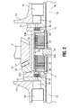
- FIG. 2 is a cross section diagram showing the rear final gear mechanism (rear differential mechanism) and the rear clutch mechanism of the rear wheel power transfer pathway for Embodiment 1.
- the vehicle drive power distribution device for Embodiment 1 is equipped with engine 1, transmission 2, front differential mechanism 3, left front wheel drive shaft 4, right front wheel drive shaft 5, left front wheel 6, right front wheel 7, transfer gear mechanism 8 (the transfer mechanism), propeller shaft 9, rear final gear mechanism 10 (the rear differential mechanism), first clutch 11, second clutch 12, left rear wheel drive shaft 13, right rear wheel drive shaft 14, left rear wheel 15 and right rear wheel 16.
- the power source is made up of engine 1 and transmission 2.
- the front wheel power transfer pathway which transfers the motive power from the power source to the left and right front wheels 6 and 7, is comprised of transmission output gear 17, drive gear 18, front differential mechanism 3, which permits the differential of the motive power from the power source to left and right front wheels 6 and 7 and performs equidistribution.
- the front wheel power transfer pathway further includes and left front wheel drive shaft 4 and right front wheel drive shaft 5 provided on side gears 19 and 20 of front differential mechanism 3.
- the rear wheel power transfer pathway that transfers the motive power from the power source by means of engine 1 and transmission 2 via the clutch to left and right rear wheels 15 and 16 links transfer gear mechanism 8 on the front wheel side to rear final gear mechanism 10 on the rear wheel side via only propeller shaft 9, links rear final gear mechanism 10 from its drive output portion to left rear wheel drive shaft 13 via first clutch 11 and links rear final gear mechanism 10 from its drive output portion to right rear wheel drive shaft 14 via second clutch 12.
- Transfer gear mechanism 8 comprises input gear 22, which is integrally rotatable with differential case 21 of front differential mechanism 3, counter gear 23 that engages with said input gear 22, counter shaft 24 on which is provided said counter gear 23, first ring gear 25 provided on the end of said counter shaft 24, and first hypoid gear 26 provided on the end of propeller shaft 9 at the front wheel side and that engages with said first ring gear 25.
- Rear final gear mechanism 10 comprises second hypoid gear 27 (hypoid gear) provided on the end of propeller shaft 9 and second ring gear 29 (ring gear) fixed to cylindrical differential case 28 that has axis RL.
- Axis RL is the central axis of cylindrical differential case 28, left rear wheel drive shaft 13 and right rear wheel drive shaft 14.
- Second ring gear 29 engages with said second hypoid gear 27.
- Gear ratio TG of transfer gear mechanism 8 and gear ratio FG of rear final gear mechanism 10 is set as a speed-increasing gear ratio that increases the speed of rear wheels 15 and 16 more than that of front wheels 6 and 7.
- This speed-increasing gear ratio is set so that the speed of rear wheels 15 and 16 is about 2 to about 5 percent faster than that of front wheels 6 and 7 by suppressing the difference in the clutch input revolution speed to the rear wheel on the outside turning wheel side of left and right rear wheels 15 and 16 to a minimum when a great deal of cornering is required for the turn in order to reduce the drive power transfer loss.
- First clutch 11 and second clutch 12 are independent variable control type clutches that independently control the switching of the transfer torque from the outside.
- Cylindrical differential case 28 is provided with partition wall 30 in the middle of the inner surface of the cylinder, first clutch chamber 31 and second clutch chamber 32 are formed separately from said partition wall 30, and first clutch 11 is disposed in first clutch chamber 31 and second clutch 12 is disposed in second clutch chamber 32.
- first clutch 11 is a multiple disk clutch comprised of first spline teeth 33a formed on the inner surface of first clutch chamber 31 of cylindrical differential case 28 and first main clutch plate 37 (the first clutch plate) inserted between the ends of left rear wheel drive shaft 13, which is inserted into first clutch chamber 31.
- This electromagnetic clutch, first clutch 11 comprises first pilot clutch plate 35 that generates constraining torque in accordance with the coil current command sent to first electromagnet 34, first ball cam 36 that generates the cam force in accordance with the constraining torque of first pilot clutch plate 35, and first main clutch plate 37 that generates the transfer torque by means of the thrust from the cam force of first ball cam 36.
- second clutch 12 is a multiple disk clutch comprised of second spline teeth 33b formed on the inner surface of second clutch chamber 32 of cylindrical differential case 28 and second main clutch plate 47 (the second clutch plate) inserted between the ends of right rear wheel drive shaft 14, which is inserted into second clutch chamber 32.
- This electromagnetic clutch, second clutch 12 comprises second pilot clutch plate 45 that generates constraining torque in accordance with the coil current command sent to second electromagnet 44, second ball cam 46 that generates the cam force in accordance with the constraining torque of second pilot clutch plate 45, and second main clutch plate 47 that generates the transfer torque by means of the thrust from the cam force of second ball cam 46.
- reference numbers 51 and 52 refer to end covers for cylindrical differential case 28
- reference number 53 refers to a unit housing
- reference numbers 54 and 55 refer to bearings that support end covers 51 and 52 to unit housing 53.
- Cylindrical differential case 28 forms a plurality of through holes 30a that penetrate through partition wall 30 in the axial direction and also forms shared spline teeth 33, which are shared by first spline teeth 33a and second spline teeth 33b, along the entire length of the case only at the portion where the plurality of through holes 30a are formed.
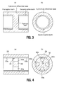
- Four through holes are formed for through holes 30a by forming 45 degree spread angles, as shown in Fig. 4, for example, to create fan-shaped through holes at equal intervals in the circumferential direction.
- the drive power distribution control to the front and rear wheels is performed by reinforcing the engaging force between first clutch 11 and second clutch 12 from the front wheel drive state in which first clutch 11 and second clutch 12 are released in order to gradually increase the drive power distribution to the rear wheels so as to reinforce the 4-wheel drive tendency, thus allowing for a seamless front-to-rear distribution.
- the drive power distribution control to left and right rear wheels 15 and 16 is performed by independently controlling the engagement/release of first clutch 11 and second clutch 12 in order to provide continuous distribution from 100 vs. 0 to 0 vs. 100, thus allowing for a seamless rear-wheel left-to-right distribution.
- the front-to-rear/rear-wheel left-to-right drive power distribution control is performed by a controller not shown in the drawing that calculates the optimum drive power distribution by detecting the operation performed by the driver and the behavior and running state of the vehicle based on information from the steering angle sensor, the transverse G sensor, the yaw rate sensor, the vehicle speed sensor and the accelerator opening sensor, and based on the result of the calculation, outputs a separate coil current command for first electromagnet 34 of first clutch 11 and second electromagnet 35 of second clutch 12.
- second clutch 12 is strongly engaged while the difference in the input/output revolution speed for clutch 12 is minimized due to the increase in speed, and first clutch 11 is either released or slightly engaged so as to create a difference in torque between left and right rear wheels 15 and 16 by making the drive torque of left rear wheel 15, which is the inside turning wheel, low, and the drive torque for right rear wheel 16, which is the outside turning wheel, high, and due to this difference in torque, a yaw moment occurs in the turning direction around the center of gravity of the vehicle and the cornering performance is improved.
- control is performed by applying a difference in torque between left and right rear wheels 15 and 16 so that a yaw moment occurs in the direction in which the behavior of the vehicle is stabilized due to the difference in torque between left and right rear wheels 15 and 16, or in other words, if the vehicle has a tendency to oversteer, the direction in which the vehicle will understeer around its center of gravity, thus ensuring turning stability.
- control when controlling the behavior of the vehicle by a sudden maneuver of the steering wheel when trying to avoid an obstacle or avoid swerving, control can be performed by applying a difference in torque between left and right rear wheels 15 and 16 in order to generate a yaw moment in a direction that avoids obstacles or swerving around the center of gravity of the vehicle and thereby assist in avoiding such obstacles or veering off course.
- first clutch 11 and second clutch 12 are provided on the left and right sides and the rear clutch mechanism, which independently controls the drive power of these clutches, is integrally installed as one unit on cylindrical differential case 28, said cylindrical differential case 28 must have a function in which it is mated to the clutch plate and a function in which it receives the reactive force of first clutch 11 and second clutch 12.
- a structure such as that shown in Fig. 3, is provided in which first spline teeth and second spline teeth are formed on the inner surface of the case so as to mate with the clutch plate, and a partition wall is provided in the middle for receiving the reactive force, thus forming the first spline teeth and the second spline teeth by means of a milling process performed from both sides.
- the spline teeth processing performance deteriorates because the tooth-cutting process involves two processes, and the spline teeth can only be processed up to the area near the partition wall.
- a problem occurs in that the total mass increases in order to ensure the thickness of the partition wall.
- cylindrical differential case 28 forms a plurality of through holes 30a that penetrate through partition wall 30 in the axial direction and also forms shared spline teeth 33, which are shared by first spline teeth 33a and second spline teeth 33b, along the entire length of the case only at the portion where the plurality of through holes 30a are formed. Therefore, only one process from one direction need be performed for the tooth-cutting process and shared spline teeth 33 that are formed continuously even at partition wall 30 can be processed, resulting in improved processing performance of shared spline teeth 33.
- through-holes 30a in partition wall 30, for which the thickness has been ensured the total mass is reduced by the amount that is taken up by through-holes 30a, allowing for a reduction in weight.
- Effect 1 For the vehicle drive power distribution device equipped with a front wheel power transfer pathway that transfers the motive power from the motive power source to left and right front wheels 6 and 7 and a rear wheel power transfer pathway that transfers the motive power from the motive power source to left and right rear wheels 15 and 16 via a clutch, the aforementioned rear wheel power transfer pathway links transfer gear mechanism 8 at the front wheel side to rear final gear mechanism 10 at the rear wheel side via only propeller shaft 9, links aforementioned rear final gear mechanism 10 from its drive output portion to left rear wheel drive shaft 13 via first clutch 11, links aforementioned rear final gear mechanism 10 from its drive output portion to right rear wheel drive shaft 14 via second clutch 12, sets the gear ratio TG of aforementioned transfer gear mechanism 8 and the gear ratio FG of aforementioned rear final gear mechanism 10 to the speed-increasing gear ratio that increases the speed of rear wheels 15 and 16 to be faster than that of front wheels 6 and 7, and since first clutch 11 and second clutch 12 are independent variable control type clutches that independently control the switching of the transfer torque from the outside, a greater degree of freedom in constitu
- Effect 2 Since the speed-increasing gear ratio obtained from the gear ratio TG of transfer gear mechanism 8 and the gear ratio FG of rear final gear mechanism 10 is set to increase the speed of rear wheels 15 and 16 by about 2 to about 5 percent more than that of front wheels 6 and 7, when the clutch on the right rear wheel side, which is the outside turning wheel of left and right rear wheels 15 and 16, is engaged when accelerating while turning, the drive power transfer loss is appropriately reduced and the cornering performance can be improved.
- Rear final gear mechanism 10 is fixed to second hypoid gear 27 provided on the end of propeller shaft 9 and cylindrical differential case 28 that is the central axis of axle RL of left and right rear wheels 15 and 16 and is comprised of second hypoid gear 27 and second ring gear 29 that engages with second hypoid gear 27.
- Cylindrical differential case 28 is provided with partition wall 30 positioned in its middle portion on the inner surface of the cylinder.
- First clutch chamber 31 and second clutch chamber 32 are formed separately from the partition wall 30, and first clutch 11 is disposed in first clutch chamber 31 and second clutch 12 is disposed in second clutch chamber 32 so as to ensure that partition wall 30 serves to receive the reactive force of clutches 11 and 12 and allow for first clutch 11 and second clutch 12 to be compactly housed inside of cylindrical differential case 28.
- first clutch 11 is a multiple disk clutch with first spline teeth 33a formed on the inner surface of first clutch chamber 31 of cylindrical differential case 28 and first main clutch plate 37 inserted between the ends of left rear wheel drive shaft 13, which is inserted into first clutch chamber
- second clutch 12 is a multiple disk clutch with second spline teeth 33b formed on the inner surface of second clutch chamber 32 of cylindrical differential case 28 and second main clutch plate 47 inserted between the ends of right rear wheel drive shaft 14, which is inserted into second clutch chamber 32, the function whereby clutch plates 37 and 47 are mated together is ensured while allowing for first clutch 11 and second clutch 12 to be compactly housed inside of cylindrical differential case 28.
- cylindrical differential case 28 forms a plurality of through holes 30a that penetrate through partition wall 30 in the axial direction and also forms shared spline teeth 33 shared by first spline teeth 33a and second spline teeth 33b along the entire length of the case only at the portion where the plurality of through holes 30a are formed, improved workability can be achieved in the spline processing and a lighter device can be realized.
- first clutch 11 and second clutch 12 each comprise pilot clutch plates 35 and 45 that generate constraining torque in accordance with the coil current command sent to electromagnets 34 and 44, ball cams 36 and 46 that generate the cam force in accordance with the constraining torque of pilot clutch plates 35 and 45, and main clutch plates 37 and 47 that generate the transfer torque by means of the thrust from the cam force of ball cams 36 and 46, first clutch 11 and second clutch 12, including the clutch control actuator, can be more compactly housed into the unit than if a motor-type clutch or a hydraulic-type clutch were used.
- Embodiment 2 is an example of a motor-type clutch in which the motor of clutch 1 and clutch 2 functions as an actuator.
- first clutch 11 comprises first ball cam 63 that generates the cam force via first cam plate 62 in accordance with the drive command sent to first motor 61 and first clutch plate 64 that generates the transfer torque by means of the thrust from the cam force of first ball cam 63.
- Second clutch 12 comprises second ball cam 73 that generates the cam force via second cam plate 72 in accordance with the drive command sent to second motor 71 and second clutch plate 74 that generates the transfer torque by means of the thrust from the cam force of second ball cam 73.
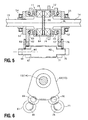
- first motor axis M1 and second motor axis M2 are parallel to axle RL of left and right rear wheels 15 and 16, and as shown in Fig. 6, are disposed so as to overlap with one another in the circumferential direction by differing the positions in which first cam plate 62 and second cam plate 72 engage with one another on their circumference.
- the rest of the constitution for Embodiment 2 is the same as that of Embodiment 1, so an explanation has been omitted for the same reference symbols that correspond to the same constitution.
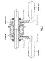
- the two motor axes M1 and M2 are parallel to axle RL of left and right rear wheels 15 and 16, and are disposed so as to overlap with one another in the circumferential direction by differing the positions in which first cam plate 62 and second cam plate 72 engage with one another on their circumference so that the space in the axial direction that is occupied by the two motors, as shown in Fig. 5, is reduced substantially compared to that shown in Fig. 7, the freedom in constituting the layout is improved, and the problem of interfering with the surrounding members can be avoided.
- the drive power distribution control operation for Embodiment 2 is the same as that for Embodiment 1 so further explanation has been omitted.
- first clutch 11 and second clutch 12 each comprise ball cams 63 and 73 that generate the cam force via cam plates 62 and 72, in accordance with the drive command sent to motors 61 and 71, and clutch plates 64 and 74 that generate the transfer torque by means of the thrust from the cam force of said ball cams 63 and 73 and since the two motor axes M1 and M2 of first motor 61 of first clutch 11 and second motor 71 of second clutch 12 are parallel to axle RL of left and right rear wheels 15 and 16 and are disposed so as to overlap with one another in the circumferential direction by differing the positions in which first cam plate 62 and second cam plate 72 engage with one another on their circumference, first clutch 11 and second clutch 12 can be compactly housed inside the unit, even though a motor-type clutch is used, and a great deal of freedom can be ensured in constituting the layout.
- the vehicle drive power distribution device for the present invention has been explained based on Embodiments 1 and 2, but in terms of a specific constitution, the device is not limited to these embodiments and modifications and additions may be made to the design as long as they do not deviate from the gist of the invention pertaining to all of the claims of the present patent.
- Embodiment 1 For the purposes of Embodiment 1, an example of a solenoid-type clutch was used for the first and second clutches and for Embodiment 2, an example of a motor-type clutch was used.
- a hydraulic-type clutch may also be used and essentially, as long as the first clutch and second clutch are independent variable control-type clutches that independently control the switching of the transfer torque from the outside, the present invention is not limited to Embodiment 1 or 2.
- Embodiments 1 and 2 an example was provided in which the first and second clutches were built into the cylindrical differential case, but the first and second clutches could be set up independently of the drive output portion of the rear final gear mechanism and essentially, as long as the rear final gear mechanism is linked from its drive output portion to the rear wheel drive shaft via the first clutch and is linked from its drive output portion to the right rear wheel drive shaft via the second clutch, the present invention is not limited to Embodiment 1 or 2.
- a drive power distribution device for an engine-type vehicle loaded with only an engine as the motive power source was shown, but the present invention could also be applied to a hybrid vehicle loaded with an engine and a motor as the motive power source or an electrically-powered vehicle or fuel cell vehicle loaded with a motor as the motive power source. So, essentially, it can be applied to a drive power distribution device for a vehicle equipped with a front wheel power transfer pathway that transfers the motive power from the power source to the left and right front wheels and a rear wheel power transfer pathway that transfers the motive power from the power source to the left and right rear wheels via a clutch.
Landscapes
- Engineering & Computer Science (AREA)
- Mechanical Engineering (AREA)
- General Engineering & Computer Science (AREA)
- Transportation (AREA)
- Chemical & Material Sciences (AREA)
- Combustion & Propulsion (AREA)
- Physics & Mathematics (AREA)
- Electromagnetism (AREA)
- Automation & Control Theory (AREA)
- Arrangement And Driving Of Transmission Devices (AREA)
Abstract
Description
- The present invention is concerned generally with vehicle drive power distribution and relates particularly, but not exclusively, to a vehicle drive power distribution device in which the front wheels and rear wheels are driven by motive power from a motive power source. Aspects of the invention also relate to an apparatus, to a method and to a vehicle.
- An example, such as unexamined Patent Application Publication No.
H2-283529 - For the conventional vehicle drive power distribution device, since the transmission provided midstream of the propeller shaft arranged between the transfer mechanism and the rear differential mechanism comprised a speed-increasing gear train, a constant speed clutch, and a speed-increasing clutch, this created a problem in that no other component could be disposed between the transfer mechanism and the rear differential mechanism.
- It is an aim of the invention to improve upon such known technology. Other aims and advantages of the invention will become apparent from the following description, claims and drawings.
- Aspects of the invention provide an apparatus, a method and a vehicle as claimed in the appended claims.
- According to another aspect of the invention there is provided a vehicle drive power distribution device in which left and right front wheels thereof and left and right rear wheels thereof are driven by a motive power source, the vehicle drive power distribution device comprising a transfer mechanism that distributes motive power from the motive power source to the left and right front wheels and left and right rear wheels, a rear differential mechanism that transfers the motive power transferred from the motive power source via the transfer mechanism to the left and right rear wheels, a first clutch provided between the rear differential mechanism and the left rear wheel, a second clutch provided between the rear differential mechanism and the right rear wheel, a control device that independently controls an engaged state of the first clutch and an engaged state of the second clutch and a speed-increasing mechanism that sets a revolution speed of an output shaft of the transfer mechanism and a revolution speed of an input shaft of the rear differential mechanism to be the same and sets a speed of the outer circumference of the rear wheel to which the motive power is transferred via the engaged clutch to be faster than a speed of the outer circumference of the left and right front wheels, while at least one of either the first or second clutches is in the engaged state.
- The device may comprise a front differential mechanism that transfers the motive power from the motive power source to the left and right front wheels, wherein the transfer mechanism is linked to the front differential mechanism.
- The device may comprise a propeller shaft having a first end directly linked to the transfer mechanism and a second end directly linked to the rear differential mechanism.
- In an embodiment the first end of the propeller shaft is the output shaft of the transfer mechanism and the second end of the propeller shaft is the input shaft of the rear differential mechanism.
- In an embodiment, the transfer mechanism consists of a gear mechanism, the rear differential mechanism consists of a gear mechanism, and the speed-increasing mechanism is composed at least one of a gear ratio of the gear mechanism of the transfer mechanism or a gear ratio of the gear mechanism of the rear differential mechanism.
- According to another aspect of the invention there is provided a vehicle drive power distribution device in which left and right front wheels thereof and left and right rear wheels thereof are driven by a motive power source, the vehicle drive power distribution device comprising a front wheel power transfer pathway that transfers motive power from the motive power source to the left and right front wheels, a rear wheel power transfer pathway that transfers the motive power from the motive power source to the left and right rear wheels and a linking pathway that links the front wheel power transfer pathway to the rear wheel power transfer pathway, wherein the linking pathway consists only of a transfer gear mechanism and a propeller shaft, wherein the rear wheel power transfer pathway comprises a rear final gear mechanism that is linked to the linking pathway, a left rear wheel drive shaft that is linked to the rear final gear mechanism via a first clutch, and a right rear wheel drive shaft that is linked to the rear final gear mechanism via a second clutch, wherein at least one of a transfer mechanism gear ratio or a rear final gear mechanism gear ratio is a speed-increasing gear ratio that increases the speed of the left and right rear wheels more than that of the left and right front wheels and wherein the first clutch and the second clutch are independent variable control type clutches that control the motive power that is independently transferred by each clutch.
- In an embodiment, the front wheel power transfer pathway comprises a front differential gear mechanism provided between the motive power source and the left and right front wheels, and the front differential gear mechanism is linked to the transfer gear mechanism.
- In an embodiment, the front wheel power transfer pathway is linked to the transfer gear mechanism and the rear wheel power transfer pathway is linked to the propeller shaft.
- In an embodiment, the speed-increasing gear ratio is set to increase the speed of the rear wheels by about 2 to about 5 percent more than that of the front wheels.
- In an embodiment, the rear final gear mechanism comprises a hypoid gear provided on an end of the propeller shaft and a ring gear that engages with the hypoid gear, the ring gear fixed to a cylindrical differential case.
- In an embodiment, a partition wall is provided in the middle of an inner surface of the cylinder of the cylindrical differential case and a first clutch chamber and a second clutch chamber are formed separately on either side of the partition wall, the first clutch is disposed in the first clutch chamber and the second clutch is disposed in the second clutch chamber.
- In an embodiment, the first clutch is a multiple disk clutch comprising a first clutch plate inserted between first spline teeth formed on the inner surface of the first clutch chamber of the cylindrical differential case and an end of the left rear wheel drive shaft which is inserted into the first clutch chamber, and wherein the second clutch is a multiple disk clutch comprising a second clutch plate inserted between second spline teeth formed on the inner surface of the second clutch chamber of the cylindrical differential case and an end of the right rear wheel drive shaft which is inserted into the second clutch chamber.
- In an embodiment, the cylindrical differential case forms a plurality of through holes that penetrate through the partition wall in an axial direction, the cylindrical differential case also forms shared spline teeth shared by the first and second spline teeth along an entire length of the case only at a portion where the plurality of through holes are formed.
- In an embodiment, the first and second clutches each comprise a pilot clutch plate that generates constraining torque in accordance with a coil current command sent to an electromagnet of the respective clutch, a ball cam that generates cam force in accordance with the constraining torque of the pilot clutch plate, and a main clutch plate that generates transfer torque by means of thrust from the cam force of the ball cam.
- In an embodiment, wherein the first and second clutches each comprise a motor that is driven in accordance with a drive command, a cam plate that is drived by the motor, a ball cam that generates a cam force via a cam plate and a clutch plate that generates transfer torque by means of thrust from the cam force of the ball cam, and wherein a first motor shaft for the motor of the first clutch and a second motor shaft for the motor of the second clutch are parallel with an axle of the left and right rear wheels and are arranged so as to overlap with one another in a circumferential direction by differing positions in which the cam plate of the first clutch and the cam plate of the second clutch engage with one another on their circumference.
- According to a further aspect of the invention there is provided a vehicle drive power distribution device in which left and right front wheels thereof and left and right rear wheels thereof are driven by a motive power source, the vehicle drive power distribution device comprising a transfer mechanism that distributes the motive power from the motive power source to the left and right front wheels and left and right rear wheels, a rear differential mechanism that transfers the motive power transferred from the motive power source via the transfer mechanism to the left and right rear wheels, a first clutch provided between the rear differential mechanism and the left rear wheel, a second clutch provided between the rear differential mechanism and the right rear wheel, a control device that independently controls an engaged state of the first clutch and an engaged state of the second clutch and a speed-increasing mechanism that sets a revolution speed of an output shaft of the transfer mechanism and a revolution speed of an input shaft of the rear differential mechanism to be the same and sets a revolution speed of an output shaft of the engaged clutch to be larger than that of the input shaft of the transfer mechanism while at least one of either the first clutch or second clutch is in the engaged state.
- According to a still further embodiment there is provided a vehicle drive power distribution device in which left and right front wheels thereof and left and right rear wheels thereof are driven by a motive power source, the vehicle drive power distribution device comprising a transfer mechanism that distributes the motive power from the motive power source to the left and right front wheels and left and right rear wheels, a rear differential mechanism that transfers the motive power transferred from the motive power source via the transfer mechanism to the left and right rear wheels, a first clutch provided between the rear differential mechanism and the left rear wheel, a second clutch provided between the rear differential mechanism and the right rear wheel, a control device that independently controls an engaged state of the first clutch and an engaged state of the second clutch and a speed-increasing mechanism that sets a revolution speed of an output shaft of the transfer mechanism and a revolution speed of an input shaft of the rear differential mechanism to be the same and sets a revolution speed of the rear wheel to which the motive power is transferred via the engaged clutch to be faster than a revolution speed of the left and right front wheels while at least one of either the first or second clutch is in the engaged state.
- According to yet another aspect of the invention there is provided a vehicle drive power distribution device in which left and right front wheels thereof and left and right rear wheels thereof are driven by a motive power source, the vehicle drive power distribution device comprising a motive power distribution means that distributes the motive power from the motive power source to the left and right front wheels and left and right rear wheels, rear-wheel-side motive power transfer means that transfers the motive power distributed by the motive power distribution means to the left and right rear wheels, a first transfer power control means that controls the motive power transferred to the left rear wheel from the rear-wheel-side motive power transfer means, a second transfer power control means that controls the motive power transferred to the right rear wheel from the rear-wheel-side motive power transfer means and a speed-increasing means that sets revolution speeds of an output shaft of the motive power distribution means and an input shaft of the rear-wheel-side motive power transfer means to be the same, and sets a speed of the left and right rear wheels to be faster than that of the left and right front wheels.
- According to another aspect of the invention there is provided a vehicle drive power distribution device in which left and right front wheels thereof and left and right rear wheels thereof are driven by a motive power source, the vehicle drive power distribution device comprising means for distributing the motive power from the motive power source to the left and right front wheels and left and right rear wheels, means for transferring the motive power distributed by the motive power distributing means to the left and right rear wheels, means for controlling the motive power transferred to the left rear wheel from the motive power transferring means, means for controlling the motive power transferred to the right rear wheel from the motive power transferring means and means for setting revolution speeds of an output shaft of the motive power distribution means and an input shaft of the motive power transferring means to be the same, and for setting a speed of the left and right rear wheels to be faster than that of the left and right front wheels.
- According to a further aspect of the invention there is provided a method for distributing motive power to left and right front wheels and left and right rear wheels of a motor vehicle, comprising forming a front wheel power transfer pathway between the left and right front wheels and a motive power source, forming a rear wheel power transfer pathway between the left and right rear wheels and the motive power source and forming a linking pathway that links the front wheel power transfer pathway to the rear wheel power transfer pathway, wherein the linking pathway consists only of a transfer gear mechanism and a propeller shaft, wherein the rear wheel power transfer pathway comprises a rear final gear mechanism that is linked to the linking pathway, a left rear wheel drive shaft that is linked to the rear final gear mechanism via a first clutch, and a right rear wheel drive shaft that is linked to the rear final gear mechanism via a second clutch, wherein at least one of gear ratios of either a transfer mechanism gear ratio or a rear final gear mechanism gear ratio is a speed-increasing gear ratio that increases the speed of the left and right rear wheels more than that of the left and right front wheels and wherein the first clutch and the second clutch are independent variable control type clutches that control motive power that is independently transferred by each clutch.
- An embodiment of the present invention provides a vehicle drive power distribution device that can achieve a rear wheel speed-increasing function and a left and right drive power independent control function, while ensuring the space between the transfer mechanism and the rear differential mechanism.
- For one embodiment, a vehicle drive power distribution device, in which the left and right front wheels and left and right rear wheels are driven by motive power from a motive power source, includes a transfer mechanism that distributes the motive power from the aforementioned power source to the left and right front wheels and the left and right rear wheels, a rear differential mechanism that transfers the motive power transferred from the aforementioned power source via the aforementioned transfer mechanism to the left and right rear wheels, a first clutch provided between the rear differential mechanism and the left rear wheel, a second clutch provided between the rear differential mechanism and the right rear wheel, a control device that independently controls the engaged state of the first clutch and the engaged state of the second clutch, and a speed-increasing mechanism that sets the revolution speed of the output shaft of the transfer mechanism and the revolution speed of the input shaft of the rear differential mechanism to be the same and sets the speed of the outer circumference of the rear wheel to which the motive power is transferred via the engaged clutch to be faster than the speed of the outer circumference of the left and right front wheels, while at least one of either the first or second clutches is in the engaged state.
- For other embodiments of the vehicle drive power distribution device, the moving speed of the rear wheels can be made faster than that of the front wheels without shifting gears between the transfer mechanism and the rear differential at the rear wheel side. In other words, the space between the transfer mechanism and the rear differential mechanism can be ensured, thus allowing for a greater degree of freedom in constituting the layout as compared to when a transmission for shifting gears is disposed between the transfer mechanism and the rear differential mechanism at the rear wheel side.
- Within the scope of this application it is envisaged that the various aspects, embodiments and alternatives set out in the preceding paragraphs, in the claims and in the following description may be taken individually or in any combination thereof.
- The present invention will now be described, by way of example only, with reference to the accompanying drawings in which:
- FIG. 1 is a skeleton diagram showing the drive system for a four-wheel drive vehicle with a four-wheel drive base to which the drive power distribution device for Embodiment 1 has been applied;
- FIG. 2 is a cross-sectional diagram showing the rear final gear mechanism and the rear clutch mechanism of the rear wheel power transfer pathway for Embodiment 1;
- FIG. 3 is a cross-sectional diagram showing an example of conventional spline teeth processing for when a partition wall is installed in the middle of the inner surface of the cylindrical differential case;
- FIG. 4 is a cross-sectional diagram showing the spline teeth processing for when a partition wall with a plurality of through-holes is installed in the middle of the inner surface of the cylindrical differential case for Embodiment 1;
- FIG. 5 is a cross-sectional diagram showing the rear final gear mechanism and the rear clutch mechanism of the rear wheel power transfer pathway for
Embodiment 2; - FIG. 6 is a side view of the positional relationship between the first motor of the first clutch and the second motor of the second clutch for
Embodiment 2; and - FIG. 7 is a cross section diagram showing an example of a conventional rear final gear mechanism and the rear clutch mechanism of the rear wheel power transfer pathway for when a motor-type clutch is used.
- Next is provided a detailed explanation of exemplary embodiments of the present invention with reference to
Embodiments 1 and 2, as shown in the drawings. - FIG. 1 is a skeleton diagram of the drive system for a four-wheel drive vehicle with a four-wheel drive base to which the drive power distribution device for Embodiment 1 has been applied. FIG. 2 is a cross section diagram showing the rear final gear mechanism (rear differential mechanism) and the rear clutch mechanism of the rear wheel power transfer pathway for Embodiment 1. As shown in FIG. 1, the vehicle drive power distribution device for Embodiment 1 is equipped with engine 1,
transmission 2, frontdifferential mechanism 3, left frontwheel drive shaft 4, right frontwheel drive shaft 5, left front wheel 6, right front wheel 7, transfer gear mechanism 8 (the transfer mechanism),propeller shaft 9, rear final gear mechanism 10 (the rear differential mechanism), first clutch 11, second clutch 12, left rearwheel drive shaft 13, right rearwheel drive shaft 14, leftrear wheel 15 and right rear wheel 16. - The power source is made up of engine 1 and
transmission 2. The front wheel power transfer pathway, which transfers the motive power from the power source to the left and right front wheels 6 and 7, is comprised oftransmission output gear 17,drive gear 18, frontdifferential mechanism 3, which permits the differential of the motive power from the power source to left and right front wheels 6 and 7 and performs equidistribution. The front wheel power transfer pathway further includes and left frontwheel drive shaft 4 and right frontwheel drive shaft 5 provided on side gears 19 and 20 of frontdifferential mechanism 3. - The rear wheel power transfer pathway that transfers the motive power from the power source by means of engine 1 and
transmission 2 via the clutch to left and rightrear wheels 15 and 16 links transfergear mechanism 8 on the front wheel side to rearfinal gear mechanism 10 on the rear wheel side viaonly propeller shaft 9, links rearfinal gear mechanism 10 from its drive output portion to left rearwheel drive shaft 13 via first clutch 11 and links rearfinal gear mechanism 10 from its drive output portion to right rearwheel drive shaft 14 viasecond clutch 12. -
Transfer gear mechanism 8 comprisesinput gear 22, which is integrally rotatable withdifferential case 21 of frontdifferential mechanism 3,counter gear 23 that engages with saidinput gear 22,counter shaft 24 on which is provided saidcounter gear 23,first ring gear 25 provided on the end of saidcounter shaft 24, andfirst hypoid gear 26 provided on the end ofpropeller shaft 9 at the front wheel side and that engages with saidfirst ring gear 25. - Rear
final gear mechanism 10 comprises second hypoid gear 27 (hypoid gear) provided on the end ofpropeller shaft 9 and second ring gear 29 (ring gear) fixed to cylindricaldifferential case 28 that has axis RL. Axis RL is the central axis of cylindricaldifferential case 28, left rearwheel drive shaft 13 and right rearwheel drive shaft 14.Second ring gear 29 engages with saidsecond hypoid gear 27. - Gear ratio TG of
transfer gear mechanism 8 and gear ratio FG of rearfinal gear mechanism 10 is set as a speed-increasing gear ratio that increases the speed ofrear wheels 15 and 16 more than that of front wheels 6 and 7. This speed-increasing gear ratio is set so that the speed ofrear wheels 15 and 16 is about 2 to about 5 percent faster than that of front wheels 6 and 7 by suppressing the difference in the clutch input revolution speed to the rear wheel on the outside turning wheel side of left and rightrear wheels 15 and 16 to a minimum when a great deal of cornering is required for the turn in order to reduce the drive power transfer loss. - First clutch 11 and second clutch 12 are independent variable control type clutches that independently control the switching of the transfer torque from the outside. Cylindrical
differential case 28 is provided withpartition wall 30 in the middle of the inner surface of the cylinder, firstclutch chamber 31 and secondclutch chamber 32 are formed separately from saidpartition wall 30, and first clutch 11 is disposed in firstclutch chamber 31 and second clutch 12 is disposed in secondclutch chamber 32. - As shown in Fig. 2, aforementioned first clutch 11 is a multiple disk clutch comprised of
first spline teeth 33a formed on the inner surface of firstclutch chamber 31 of cylindricaldifferential case 28 and first main clutch plate 37 (the first clutch plate) inserted between the ends of left rearwheel drive shaft 13, which is inserted into firstclutch chamber 31. This electromagnetic clutch, first clutch 11, comprises first pilotclutch plate 35 that generates constraining torque in accordance with the coil current command sent tofirst electromagnet 34,first ball cam 36 that generates the cam force in accordance with the constraining torque of first pilotclutch plate 35, and first mainclutch plate 37 that generates the transfer torque by means of the thrust from the cam force offirst ball cam 36. - As shown in Fig. 2, second clutch 12 is a multiple disk clutch comprised of
second spline teeth 33b formed on the inner surface of secondclutch chamber 32 of cylindricaldifferential case 28 and second main clutch plate 47 (the second clutch plate) inserted between the ends of right rearwheel drive shaft 14, which is inserted into secondclutch chamber 32. This electromagnetic clutch, second clutch 12, comprises second pilotclutch plate 45 that generates constraining torque in accordance with the coil current command sent tosecond electromagnet 44,second ball cam 46 that generates the cam force in accordance with the constraining torque of second pilotclutch plate 45, and second mainclutch plate 47 that generates the transfer torque by means of the thrust from the cam force ofsecond ball cam 46. In Fig. 2,reference numbers differential case 28,reference number 53 refers to a unit housing, andreference numbers unit housing 53. - Cylindrical
differential case 28 forms a plurality of throughholes 30a that penetrate throughpartition wall 30 in the axial direction and also forms sharedspline teeth 33, which are shared byfirst spline teeth 33a andsecond spline teeth 33b, along the entire length of the case only at the portion where the plurality of throughholes 30a are formed. Four through holes are formed for throughholes 30a by forming 45 degree spread angles, as shown in Fig. 4, for example, to create fan-shaped through holes at equal intervals in the circumferential direction. - For the drive power distribution device described in Embodiment 1, the drive power distribution control to the front and rear wheels is performed by reinforcing the engaging force between first clutch 11 and second clutch 12 from the front wheel drive state in which first clutch 11 and second clutch 12 are released in order to gradually increase the drive power distribution to the rear wheels so as to reinforce the 4-wheel drive tendency, thus allowing for a seamless front-to-rear distribution. In addition, the drive power distribution control to left and right
rear wheels 15 and 16 is performed by independently controlling the engagement/release of first clutch 11 and second clutch 12 in order to provide continuous distribution from 100 vs. 0 to 0 vs. 100, thus allowing for a seamless rear-wheel left-to-right distribution. - Furthermore, the front-to-rear/rear-wheel left-to-right drive power distribution control is performed by a controller not shown in the drawing that calculates the optimum drive power distribution by detecting the operation performed by the driver and the behavior and running state of the vehicle based on information from the steering angle sensor, the transverse G sensor, the yaw rate sensor, the vehicle speed sensor and the accelerator opening sensor, and based on the result of the calculation, outputs a separate coil current command for
first electromagnet 34 of first clutch 11 andsecond electromagnet 35 of second clutch 12. - Therefore, when traveling at cruising speed on straight roads in the front-wheel drive state in which first clutch 11 and second clutch 12 are released, loss can be suppressed to a minimum and an excellent fuel consumption rate can be achieved. In addition, when taking off or accelerating forward in a straight direction, the drive power distribution to the rear wheels is gradually increased so as to reinforce the 4-wheel drive tendency and achieve excellent drive performance by suppressing the drive slip.
- On the other hand, when accelerating while turning, since the rear wheel on the outside turning wheel side of left and right
rear wheels 15 and 16 passes through a trajectory that is more on the outside than the average trajectory of left and right front wheels 6 and 7, the rear wheel on the outside turning wheel side cannot catch up with the front wheels if all four wheels are rotating at the same speed, resulting in a phenomenon whereby the drive power cannot be efficiently transferred to the rear wheel on the outside turning wheel side. Conversely, for Embodiment 1, since the speed ofrear wheels 15 and 16 is set to be faster than that of front wheels 6 and 7 by means of the gear ratio TG setting fortransfer gear mechanism 8 and the gear ratio FG setting for rearfinal gear mechanism 10, the loss in drive power transfer is reduced due to the difference in trajectory between the front and rear wheels when turning, resulting in improved turning movement performance of the vehicle. - Therefore, for example, when right rear wheel 16 is the outside turning wheel when the vehicle turns left, second clutch 12 is strongly engaged while the difference in the input/output revolution speed for
clutch 12 is minimized due to the increase in speed, and first clutch 11 is either released or slightly engaged so as to create a difference in torque between left and rightrear wheels 15 and 16 by making the drive torque of leftrear wheel 15, which is the inside turning wheel, low, and the drive torque for right rear wheel 16, which is the outside turning wheel, high, and due to this difference in torque, a yaw moment occurs in the turning direction around the center of gravity of the vehicle and the cornering performance is improved. - Furthermore, when decelerating during the turn with the accelerator off, control is performed by applying a difference in torque between left and right
rear wheels 15 and 16 so that a yaw moment occurs in the direction in which the behavior of the vehicle is stabilized due to the difference in torque between left and rightrear wheels 15 and 16, or in other words, if the vehicle has a tendency to oversteer, the direction in which the vehicle will understeer around its center of gravity, thus ensuring turning stability. - In addition, when controlling the behavior of the vehicle by a sudden maneuver of the steering wheel when trying to avoid an obstacle or avoid swerving, control can be performed by applying a difference in torque between left and right
rear wheels 15 and 16 in order to generate a yaw moment in a direction that avoids obstacles or swerving around the center of gravity of the vehicle and thereby assist in avoiding such obstacles or veering off course. - For a constitution in which first clutch 11 and second clutch 12 are provided on the left and right sides and the rear clutch mechanism, which independently controls the drive power of these clutches, is integrally installed as one unit on cylindrical
differential case 28, said cylindricaldifferential case 28 must have a function in which it is mated to the clutch plate and a function in which it receives the reactive force of first clutch 11 and second clutch 12. - In order to satisfy the aforementioned functions, a structure, such as that shown in Fig. 3, is provided in which first spline teeth and second spline teeth are formed on the inner surface of the case so as to mate with the clutch plate, and a partition wall is provided in the middle for receiving the reactive force, thus forming the first spline teeth and the second spline teeth by means of a milling process performed from both sides. However, when this is performed, the spline teeth processing performance deteriorates because the tooth-cutting process involves two processes, and the spline teeth can only be processed up to the area near the partition wall. In addition, a problem occurs in that the total mass increases in order to ensure the thickness of the partition wall.
- In order to counteract the aforementioned problems, for the drive power distribution device in Embodiment 1, cylindrical
differential case 28 forms a plurality of throughholes 30a that penetrate throughpartition wall 30 in the axial direction and also forms sharedspline teeth 33, which are shared byfirst spline teeth 33a andsecond spline teeth 33b, along the entire length of the case only at the portion where the plurality of throughholes 30a are formed. Therefore, only one process from one direction need be performed for the tooth-cutting process and sharedspline teeth 33 that are formed continuously even atpartition wall 30 can be processed, resulting in improved processing performance of sharedspline teeth 33. In addition, by forming through-holes 30a inpartition wall 30, for which the thickness has been ensured, the total mass is reduced by the amount that is taken up by through-holes 30a, allowing for a reduction in weight. - The following effects, as described below, can be achieved for the vehicle drive power distribution device pertaining to Embodiment 1.
- Effect 1: For the vehicle drive power distribution device equipped with a front wheel power transfer pathway that transfers the motive power from the motive power source to left and right front wheels 6 and 7 and a rear wheel power transfer pathway that transfers the motive power from the motive power source to left and right rear wheels 15 and 16 via a clutch, the aforementioned rear wheel power transfer pathway links transfer gear mechanism 8 at the front wheel side to rear final gear mechanism 10 at the rear wheel side via only propeller shaft 9, links aforementioned rear final gear mechanism 10 from its drive output portion to left rear wheel drive shaft 13 via first clutch 11, links aforementioned rear final gear mechanism 10 from its drive output portion to right rear wheel drive shaft 14 via second clutch 12, sets the gear ratio TG of aforementioned transfer gear mechanism 8 and the gear ratio FG of aforementioned rear final gear mechanism 10 to the speed-increasing gear ratio that increases the speed of rear wheels 15 and 16 to be faster than that of front wheels 6 and 7, and since first clutch 11 and second clutch 12 are independent variable control type clutches that independently control the switching of the transfer torque from the outside, a greater degree of freedom in constituting the layout is ensured, friction loss, the cost and the weight can be reduced and a rear wheel speed-increasing function as well as a left/right drive power independent control function are achieved.
- Effect 2: Since the speed-increasing gear ratio obtained from the gear ratio TG of
transfer gear mechanism 8 and the gear ratio FG of rearfinal gear mechanism 10 is set to increase the speed ofrear wheels 15 and 16 by about 2 to about 5 percent more than that of front wheels 6 and 7, when the clutch on the right rear wheel side, which is the outside turning wheel of left and rightrear wheels 15 and 16, is engaged when accelerating while turning, the drive power transfer loss is appropriately reduced and the cornering performance can be improved. - Effect 3: Rear
final gear mechanism 10 is fixed tosecond hypoid gear 27 provided on the end ofpropeller shaft 9 and cylindricaldifferential case 28 that is the central axis of axle RL of left and rightrear wheels 15 and 16 and is comprised ofsecond hypoid gear 27 andsecond ring gear 29 that engages withsecond hypoid gear 27. Cylindricaldifferential case 28 is provided withpartition wall 30 positioned in its middle portion on the inner surface of the cylinder. Firstclutch chamber 31 and secondclutch chamber 32 are formed separately from thepartition wall 30, and first clutch 11 is disposed in firstclutch chamber 31 and second clutch 12 is disposed in secondclutch chamber 32 so as to ensure thatpartition wall 30 serves to receive the reactive force ofclutches differential case 28. - Effect 4: Since first clutch 11 is a multiple disk clutch with
first spline teeth 33a formed on the inner surface of firstclutch chamber 31 of cylindricaldifferential case 28 and first mainclutch plate 37 inserted between the ends of left rearwheel drive shaft 13, which is inserted into firstclutch chamber 31, and second clutch 12 is a multiple disk clutch withsecond spline teeth 33b formed on the inner surface of secondclutch chamber 32 of cylindricaldifferential case 28 and second mainclutch plate 47 inserted between the ends of right rearwheel drive shaft 14, which is inserted into secondclutch chamber 32, the function wherebyclutch plates differential case 28. - Effect 5: Since cylindrical
differential case 28 forms a plurality of throughholes 30a that penetrate throughpartition wall 30 in the axial direction and also forms sharedspline teeth 33 shared byfirst spline teeth 33a andsecond spline teeth 33b along the entire length of the case only at the portion where the plurality of throughholes 30a are formed, improved workability can be achieved in the spline processing and a lighter device can be realized. - Effect 6: Since first clutch 11 and second clutch 12 each comprise pilot
clutch plates electromagnets ball cams clutch plates clutch plates ball cams -
Embodiment 2 is an example of a motor-type clutch in which the motor of clutch 1 and clutch 2 functions as an actuator. - As shown in Fig. 5, first clutch 11 comprises
first ball cam 63 that generates the cam force viafirst cam plate 62 in accordance with the drive command sent tofirst motor 61 and firstclutch plate 64 that generates the transfer torque by means of the thrust from the cam force offirst ball cam 63. Second clutch 12 comprisessecond ball cam 73 that generates the cam force viasecond cam plate 72 in accordance with the drive command sent tosecond motor 71 and secondclutch plate 74 that generates the transfer torque by means of the thrust from the cam force ofsecond ball cam 73. - As shown in Fig. 5, for
first motor 61 of first clutch 11 andsecond motor 71 of second clutch 12, first motor axis M1 and second motor axis M2 are parallel to axle RL of left and rightrear wheels 15 and 16, and as shown in Fig. 6, are disposed so as to overlap with one another in the circumferential direction by differing the positions in whichfirst cam plate 62 andsecond cam plate 72 engage with one another on their circumference. -
First motor gear 65 andfirst cam plate 62 provided on the motor shaft offirst motor 61 engage viafirst decelerating gear 66.Second motor gear 75 andsecond cam plate 72 provided on the motor shaft ofsecond motor 71 engage viasecond decelerating gear 76. The rest of the constitution forEmbodiment 2 is the same as that of Embodiment 1, so an explanation has been omitted for the same reference symbols that correspond to the same constitution. - When 2 motors are provided in the same position in the circumferential direction so as to not interfere with one another in relation to the two clutches, as shown in Fig. 7, the first clutch and the second clutch and the first motor gear and the second motor gear are positioned inward facing one another and the rear ends of the first and second motors are both positioned to face outward. In this case, the space occupied by the two motors expands in the axial direction and creates a problem by interfering with the surrounding members, resulting is less freedom in the layout of the constitution.
- On the other hand, for the drive distribution device in
Embodiment 2, the two motor axes M1 and M2 are parallel to axle RL of left and rightrear wheels 15 and 16, and are disposed so as to overlap with one another in the circumferential direction by differing the positions in whichfirst cam plate 62 andsecond cam plate 72 engage with one another on their circumference so that the space in the axial direction that is occupied by the two motors, as shown in Fig. 5, is reduced substantially compared to that shown in Fig. 7, the freedom in constituting the layout is improved, and the problem of interfering with the surrounding members can be avoided. The drive power distribution control operation forEmbodiment 2 is the same as that for Embodiment 1 so further explanation has been omitted. - For the vehicle drive power distribution device for
Embodiment 2, in addition to Effects 1-5 described above in conjunction with Embodiment 1, the following effect can also be achieved. - Effect 7: Since first clutch 11 and second clutch 12 each comprise
ball cams cam plates motors clutch plates ball cams first motor 61 of first clutch 11 andsecond motor 71 of second clutch 12 are parallel to axle RL of left and rightrear wheels 15 and 16 and are disposed so as to overlap with one another in the circumferential direction by differing the positions in whichfirst cam plate 62 andsecond cam plate 72 engage with one another on their circumference, first clutch 11 and second clutch 12 can be compactly housed inside the unit, even though a motor-type clutch is used, and a great deal of freedom can be ensured in constituting the layout. - The vehicle drive power distribution device for the present invention has been explained based on
Embodiments 1 and 2, but in terms of a specific constitution, the device is not limited to these embodiments and modifications and additions may be made to the design as long as they do not deviate from the gist of the invention pertaining to all of the claims of the present patent. - For the purposes of Embodiment 1, an example of a solenoid-type clutch was used for the first and second clutches and for
Embodiment 2, an example of a motor-type clutch was used. However, a hydraulic-type clutch may also be used and essentially, as long as the first clutch and second clutch are independent variable control-type clutches that independently control the switching of the transfer torque from the outside, the present invention is not limited toEmbodiment 1 or 2. - For the purposes of
Embodiments 1 and 2, an example was provided in which the first and second clutches were built into the cylindrical differential case, but the first and second clutches could be set up independently of the drive output portion of the rear final gear mechanism and essentially, as long as the rear final gear mechanism is linked from its drive output portion to the rear wheel drive shaft via the first clutch and is linked from its drive output portion to the right rear wheel drive shaft via the second clutch, the present invention is not limited toEmbodiment 1 or 2. - For the purposes of
Embodiments 1 and 2, a drive power distribution device for an engine-type vehicle loaded with only an engine as the motive power source was shown, but the present invention could also be applied to a hybrid vehicle loaded with an engine and a motor as the motive power source or an electrically-powered vehicle or fuel cell vehicle loaded with a motor as the motive power source. So, essentially, it can be applied to a drive power distribution device for a vehicle equipped with a front wheel power transfer pathway that transfers the motive power from the power source to the left and right front wheels and a rear wheel power transfer pathway that transfers the motive power from the power source to the left and right rear wheels via a clutch. - The present application claims priority from
Japanese Patent Application No. 2005- 228982
Claims (14)
- An apparatus for distribution drive power in a vehicle in which left and right front wheels thereof and left and right rear wheels thereof are driven by a motive power source, the apparatus comprising:transfer means for distributing motive power from the motive power source to the left and right front wheels and left and right rear wheels;rear differential means for transferring the motive power transferred from the motive power source via the transfer means to the left and right rear wheels;first clutch means provided between the rear differential means and the left rear wheel;second clutch means provided between the rear differential mechanism and the right rear wheel;control means for controlling an engaged state of the first clutch means and an engaged state of the second clutch means; andspeed-increasing means for setting a revolution speed of an output shaft of the transfer means and a revolution speed of an input shaft of the rear differential means to be the same and for setting at least one of:i) a revolution speed of an output shaft of the engaged clutch to be greater than that of an input shaft of the transfer means; andii) a revolution speed of the rear wheel to which the motive power is transferred via the engaged clutch means to be faster than a revolution speed of the left and right front wheels;while at least one of the first clutch means and the second clutch means is in the engaged state.
- An apparatus as claimed in claim 1 comprising front differential moeans for transferring the motive power from the motive power source to the left and right front wheels, wherein the transfer means is linked to the front differential means.
- An apparatus as claimed in claim 1 or claim 2 comprising propeller shaft means having a first end directly linked to the transfer means and a second end directly linked to the rear differential means.
- An apparatus as claimed in claim 3 wherein the first end of the propeller shaft means is the output shaft of the transfer means and the second end of the propeller shaft means is the input shaft of the rear differential means.
- An apparatus as claimed in any preceding claim wherein the transfer means comprises a first gear mechanism, the rear differential means comprises a second gear mechanism and the speed-increasing means comprises at least one of a gear ratio of the first or second gear mechanisms.
- An apparatus as claimed in claim 5 wherein the speed-increasing gear ratio is arranged to increase the speed of the rear wheels by about 2 to about 5 percent more than that of the front wheels.
- An apparatus as claimed in any of claims 3 to 6 wherein the rear differential means includes a hypoid gear provided on an end of the propeller shaft means and a ring gear that engages with the hypoid gear, the ring gear being fixed to a cylindrical differential case.
- An apparatus as claimed in claim 7 wherein a partition wall is provided in the middle of an inner surface of the cylinder of the cylindrical differential case and a first clutch chamber and a second clutch chamber are formed separately on either side of the partition wall, the first clutch means being disposed in the first clutch chamber and the second clutch means being disposed in the second clutch chamber.
- An apparatus as claimed in claim 8 wherein the first clutch means is a multiple disk clutch comprising a first clutch plate inserted between first spline teeth formed on the inner surface of the first clutch chamber of the cylindrical differential case and an end of a left rear wheel drive shaft which is inserted into the first clutch chamber, and wherein the second clutch means is a multiple disk clutch comprising a second clutch plate inserted between second spline teeth formed on the inner surface of the second clutch chamber of the cylindrical differential case and an end of a right rear wheel drive shaft which is inserted into the second clutch chamber.
- An apparatus as claimed in claim 9 wherein wherein the cylindrical differential case forms a plurality of through holes that penetrate through the partition wall in an axial direction, the cylindrical differential case also forms shared spline teeth shared by the first and second spline teeth along an entire length of the case only at a portion where the plurality of through holes are formed.
- An apparatus as claimed in any preceding claim wherein the first and second clutch means each comprise a pilot clutch plate that generates constraining torque in accordance with a coil current command sent to an electromagnet of the respective clutch means, a ball cam that generates cam force in accordance with the constraining torque of the pilot clutch plate, and a main clutch plate that generates transfer torque by means of thrust from the cam force of the ball cam.
- An apparatus as claimed in any preceding claim wherein the first and second clutch means each comprise a motor that is driven in accordance with a drive command, a cam plate that is drived by the motor, a ball cam that generates a cam force via a cam plate and a clutch plate that generates transfer torque by means of thrust from the cam force of the ball cam, and wherein a first motor shaft for the motor of the first clutch means and a second motor shaft for the motor of the second clutch means are parallel with an axle of the left and right rear wheels and are arranged so as to overlap with one another in a circumferential direction by differing positions in which the cam plate of the first clutch means and the cam plate of the second clutch means engage with one another on their circumference.
- A method for distributing motive power to left and right front wheels and left and right rear wheels of a motor vehicle, comprising:forming a front wheel power transfer pathway between the left and right front wheels and a motive power source;forming a rear wheel power transfer pathway between the left and right rear wheels and the motive power source; andforming a linking pathway that links the front wheel power transfer pathway to the rear wheel power transfer pathway;wherein the linking pathway consists only of a transfer gear mechanism and a propeller shaft;
wherein the rear wheel power transfer pathway comprises a rear final gear mechanism that is linked to the linking pathway, a left rear wheel drive shaft that is linked to the rear final gear mechanism via a first clutch, and a right rear wheel drive shaft that is linked to the rear final gear mechanism via a second clutch;
wherein at least one of gear ratios of either a transfer mechanism gear ratio or a rear final gear mechanism gear ratio is a speed-increasing gear ratio that increases the speed of the left and right rear wheels more than that of the left and right front wheels; and
wherein the first clutch and the second clutch are independent variable control type clutches that control motive power that is independently transferred by each clutch. - A vehicle having an apparatus or adapted to use a method as claimed in any preceding claim.
Applications Claiming Priority (1)
| Application Number | Priority Date | Filing Date | Title |
|---|---|---|---|
| JP2005228982A JP4821208B2 (en) | 2005-08-08 | 2005-08-08 | Vehicle driving force distribution device |
Publications (3)
| Publication Number | Publication Date |
|---|---|
| EP1752330A2 true EP1752330A2 (en) | 2007-02-14 |
| EP1752330A3 EP1752330A3 (en) | 2009-11-04 |
| EP1752330B1 EP1752330B1 (en) | 2013-09-11 |
Family
ID=37421151
Family Applications (1)
| Application Number | Title | Priority Date | Filing Date |
|---|---|---|---|
| EP06253977.0A Active EP1752330B1 (en) | 2005-08-08 | 2006-07-28 | Vehicle drive power distribution |
Country Status (4)
| Country | Link |
|---|---|
| US (1) | US7530421B2 (en) |
| EP (1) | EP1752330B1 (en) |
| JP (1) | JP4821208B2 (en) |
| CN (1) | CN100475592C (en) |
Cited By (3)
| Publication number | Priority date | Publication date | Assignee | Title |
|---|---|---|---|---|
| FR2914260A1 (en) * | 2007-03-27 | 2008-10-03 | Renault Sas | Four wheeled motor vehicle e.g. industrial vehicle, for e.g. building site, has electronic control unit including auxiliary units decelerating torques to be applied on wheels found at interior or exterior of turning via units, respectively |
| WO2012072202A1 (en) * | 2010-11-30 | 2012-06-07 | Daimler Ag | Motor vehicle drive train device |
| CN105502230A (en) * | 2016-01-21 | 2016-04-20 | 安徽农业大学 | Hybrid power forklift transmission system |
Families Citing this family (41)
| Publication number | Priority date | Publication date | Assignee | Title |
|---|---|---|---|---|
| JP4783312B2 (en) * | 2007-02-27 | 2011-09-28 | 本田技研工業株式会社 | Electric vehicle |
| JP5262588B2 (en) * | 2007-12-26 | 2013-08-14 | 日産自動車株式会社 | Driving force distribution device |
| US8567540B2 (en) * | 2008-01-25 | 2013-10-29 | Ford Global Technologies, Llc | Drive unit for an electric hybrid vehicle |
| DE102008042044A1 (en) * | 2008-09-12 | 2010-03-18 | Zf Friedrichshafen Ag | Drive train arrangement for a vehicle |
| DE102008043849A1 (en) * | 2008-11-19 | 2010-05-20 | Zf Friedrichshafen Ag | Multi-axis hybrid propulsion system for a vehicle |
| KR20110129887A (en) * | 2009-03-09 | 2011-12-02 | 마그나 파워트레인 오브 아메리카, 인크. | Front wheel drive with active dry disconnect system |
| GB0910242D0 (en) * | 2009-06-15 | 2009-07-29 | Bamford Excavators Ltd | Hybrid transmission |
| EP2591936B1 (en) * | 2010-07-09 | 2015-05-20 | Nissan Motor Co., Ltd | Drive power distribution control device for four wheel drive vehicle |
| JP5720165B2 (en) | 2010-10-05 | 2015-05-20 | 株式会社ジェイテクト | Four-wheel drive vehicle |
| JP5817104B2 (en) * | 2010-11-18 | 2015-11-18 | 日産自動車株式会社 | Roller friction transmission unit |
| JP2012127235A (en) * | 2010-12-14 | 2012-07-05 | Toyota Motor Corp | Automatic engine control system |
| KR20130005407A (en) * | 2011-07-06 | 2013-01-16 | 현대모비스 주식회사 | Electric vehicle 4-wheel driven transfer apparatus |
| JP2013060147A (en) * | 2011-09-14 | 2013-04-04 | Toyota Motor Corp | Four-wheel drive vehicle |
| JP5483770B2 (en) * | 2012-09-21 | 2014-05-07 | 富士重工業株式会社 | Control device for four-wheel drive vehicle |
| JP6412678B2 (en) * | 2012-12-06 | 2018-10-24 | 株式会社ジェイテクト | Driving force transmission control device |
| JP5904185B2 (en) * | 2013-10-07 | 2016-04-13 | トヨタ自動車株式会社 | Control device for four-wheel drive vehicle |
| CN105658504B (en) * | 2013-10-21 | 2017-06-16 | 株式会社神崎高级工机制作所 | The travel transmission case of working truck |
| JP5907142B2 (en) * | 2013-10-22 | 2016-04-20 | トヨタ自動車株式会社 | Control device for four-wheel drive vehicle |
| US10295036B2 (en) | 2013-12-18 | 2019-05-21 | Gkn Automotive Ltd. | Balancing unit of a motor vehicle and method for controlling same |
| CN104742718A (en) * | 2013-12-25 | 2015-07-01 | 联合汽车电子有限公司 | Hybrid power assembly structure and control method thereof |
| US10220702B2 (en) | 2014-03-27 | 2019-03-05 | Mazda Motor Corporation | Motive force transmission device and production method therefor |
| DE102014005517A1 (en) * | 2014-04-15 | 2015-10-15 | Renk Aktiengesellschaft | Power split transmission |
| DE102015207248A1 (en) * | 2014-05-02 | 2015-11-05 | Borgwarner Inc. | DISTRIBUTION GEAR (PTU) ON FORWARD DRIVE BASE WITH HYDRAULICALLY OPERATED SEPARATION |
| WO2016011096A1 (en) | 2014-07-16 | 2016-01-21 | Dana Automotives Systems Group, LLC | A drive unit with twin side shaft torque coupling |
| US9746064B2 (en) | 2015-01-16 | 2017-08-29 | American Axle & Manufacturing, Inc. | Dual clutch drive module with single servo hydraulic pump and normally-open valve actuation |
| WO2016146201A1 (en) | 2015-03-19 | 2016-09-22 | Gkn Driveline International Gmbh | Balancing unit of a motor vehicle and method for controlling same |
| CN104859441B (en) * | 2015-05-18 | 2018-10-30 | 山东理工大学 | One kind being based on single-ended dual output operation/traveling driving motor special-purpose vehicle dynamical system |
| CN104875611A (en) * | 2015-05-18 | 2015-09-02 | 山东理工大学 | Special vehicle power system based on dual-end output work/traveling driving motor |
| US10197144B2 (en) | 2017-01-20 | 2019-02-05 | Dana Heavy Vehicle Systems Group, Llc | Drive unit with torque vectoring and an axle disconnect and reconnect mechanism |
| JP6819526B2 (en) | 2017-09-21 | 2021-01-27 | トヨタ自動車株式会社 | Control device for four-wheel drive vehicles |
| JP7136548B2 (en) | 2017-10-30 | 2022-09-13 | トヨタ自動車株式会社 | wheel speed estimator |
| JP6836196B2 (en) | 2017-11-16 | 2021-02-24 | トヨタ自動車株式会社 | Control device for four-wheel drive vehicles |
| JP6662368B2 (en) | 2017-12-28 | 2020-03-11 | トヨタ自動車株式会社 | Control device for four-wheel drive vehicle |
| JP6977685B2 (en) * | 2018-07-27 | 2021-12-08 | トヨタ自動車株式会社 | Behavior control device for four-wheel drive vehicles |
| CN109291791A (en) * | 2018-08-24 | 2019-02-01 | 平湖市科苑技术服务有限公司 | electric stroller |
| JP7159768B2 (en) | 2018-10-09 | 2022-10-25 | トヨタ自動車株式会社 | Driving control device for four-wheel drive vehicle |
| JP7089225B2 (en) * | 2018-11-13 | 2022-06-22 | トヨタ自動車株式会社 | Travel control device |
| JP7031565B2 (en) * | 2018-11-27 | 2022-03-08 | トヨタ自動車株式会社 | Control device for four-wheel drive vehicles |
| JP7414442B2 (en) * | 2019-09-20 | 2024-01-16 | 株式会社Subaru | Four-wheel drive vehicle drive system |
| US11607956B2 (en) * | 2019-10-31 | 2023-03-21 | Deere & Company | Trailing vehicle traction control system with a disconnect device |
| CN117067903A (en) * | 2023-09-21 | 2023-11-17 | 中国第一汽车股份有限公司 | All-wheel drive electric drive device and vehicle having the same |
Citations (1)
| Publication number | Priority date | Publication date | Assignee | Title |
|---|---|---|---|---|
| JPH02283529A (en) | 1989-04-24 | 1990-11-21 | Honda Motor Co Ltd | Front and rear wheels drive device for vehicle |
Family Cites Families (20)
| Publication number | Priority date | Publication date | Assignee | Title |
|---|---|---|---|---|
| JPH0680348B2 (en) * | 1984-12-13 | 1994-10-12 | アイシン・エィ・ダブリュ株式会社 | Automatic transmission for four-wheel drive vehicles |
| JPH055060Y2 (en) * | 1986-08-11 | 1993-02-09 | ||
| JPS6378821A (en) * | 1987-09-11 | 1988-04-08 | Norin Kikai Kenkyusho:Kk | All-wheel drive type vehicle |
| JP2641724B2 (en) * | 1988-01-11 | 1997-08-20 | 本田技研工業株式会社 | Left and right wheel drive system for vehicles |
| US5086867A (en) * | 1988-07-08 | 1992-02-11 | Tochigifujisangyo Kabushiki Kaisha | Power transmission apparatus |
| US5135071A (en) * | 1989-01-11 | 1992-08-04 | Honda Giken Kogyo Kabushiki Kaisha | Power transmitting apparatus for four-wheel-drive motor vehicle |
| JPH03525A (en) * | 1989-05-30 | 1991-01-07 | Honda Motor Co Ltd | Drive force distribution control device for front and rear wheel drive vehicles |
| JP2883897B2 (en) * | 1990-05-23 | 1999-04-19 | 富士重工業 株式会社 | 4-wheel drive vehicle with multi-stage automatic transmission |
| JP2738225B2 (en) * | 1992-06-15 | 1998-04-08 | 三菱自動車工業株式会社 | Left and right driving force adjustment device for vehicles |
| JP3269873B2 (en) * | 1993-02-19 | 2002-04-02 | 本田技研工業株式会社 | Power transmission device |
| JPH08247177A (en) * | 1995-03-09 | 1996-09-24 | Tochigi Fuji Ind Co Ltd | Clutch device |
| US5868642A (en) * | 1996-09-26 | 1999-02-09 | Fuji Jukogyo Kabushiki Kaisha | Right/left driving torque distributing device for vehicle |
| JP3430824B2 (en) * | 1996-11-01 | 2003-07-28 | 日産自動車株式会社 | Vehicle driving force transmission device |
| JP3652462B2 (en) * | 1997-01-14 | 2005-05-25 | 本田技研工業株式会社 | Rear differential casing structure for vehicles |
| JPH10231862A (en) * | 1997-02-21 | 1998-09-02 | Tochigi Fuji Ind Co Ltd | Clutch mechanism and differential device having the same |
| JP3505975B2 (en) * | 1997-09-19 | 2004-03-15 | 日産自動車株式会社 | Driving force transmission device for four-wheel drive vehicle |
| US5984821A (en) * | 1998-11-13 | 1999-11-16 | Borg-Warner Automotive, Inc. | Transfer case with four-wheel underdrive operating mode |
| JP2002187446A (en) * | 2000-12-21 | 2002-07-02 | Fuji Heavy Ind Ltd | Power distribution device for four-wheel drive vehicles |
| US6533090B2 (en) * | 2001-08-03 | 2003-03-18 | Gkn Automotive, Inc. | Integrated axle module with twin electronic torque management |
| JP3813561B2 (en) * | 2002-09-25 | 2006-08-23 | 本田技研工業株式会社 | Power transmission device |
-
2005
- 2005-08-08 JP JP2005228982A patent/JP4821208B2/en not_active Expired - Lifetime
-
2006
- 2006-07-28 EP EP06253977.0A patent/EP1752330B1/en active Active
- 2006-08-07 US US11/500,198 patent/US7530421B2/en active Active
- 2006-08-08 CN CNB2006101093028A patent/CN100475592C/en active Active
Patent Citations (1)
| Publication number | Priority date | Publication date | Assignee | Title |
|---|---|---|---|---|
| JPH02283529A (en) | 1989-04-24 | 1990-11-21 | Honda Motor Co Ltd | Front and rear wheels drive device for vehicle |
Cited By (5)
| Publication number | Priority date | Publication date | Assignee | Title |
|---|---|---|---|---|
| FR2914260A1 (en) * | 2007-03-27 | 2008-10-03 | Renault Sas | Four wheeled motor vehicle e.g. industrial vehicle, for e.g. building site, has electronic control unit including auxiliary units decelerating torques to be applied on wheels found at interior or exterior of turning via units, respectively |
| WO2012072202A1 (en) * | 2010-11-30 | 2012-06-07 | Daimler Ag | Motor vehicle drive train device |
| US8893584B2 (en) | 2010-11-30 | 2014-11-25 | Daimler Ag | Motor vehicle drive train device |
| CN105502230A (en) * | 2016-01-21 | 2016-04-20 | 安徽农业大学 | Hybrid power forklift transmission system |
| CN105502230B (en) * | 2016-01-21 | 2017-10-27 | 安徽农业大学 | A kind of hybrid electric forklift transmission system |
Also Published As
| Publication number | Publication date |
|---|---|
| CN100475592C (en) | 2009-04-08 |
| JP2007045194A (en) | 2007-02-22 |
| JP4821208B2 (en) | 2011-11-24 |
| US7530421B2 (en) | 2009-05-12 |
| US20070029127A1 (en) | 2007-02-08 |
| EP1752330B1 (en) | 2013-09-11 |
| EP1752330A3 (en) | 2009-11-04 |
| CN1911700A (en) | 2007-02-14 |
Similar Documents
| Publication | Publication Date | Title |
|---|---|---|
| EP1752330B1 (en) | Vehicle drive power distribution | |
| US7467678B2 (en) | Hybrid four-wheel-drive | |
| EP3380352B1 (en) | A vehicle driveline system | |
| EP2727757B1 (en) | Driving force transmission device and vehicle having said driving force transmission device | |
| US9333853B2 (en) | Torque vectoring axle assembly | |
| EP2701935B1 (en) | Vehicle and method of controlling a vehicle | |
| US10059323B2 (en) | Vehicle driving system | |
| US20100285917A1 (en) | Differential gear | |
| CN101315122A (en) | means operable to distribute driving force | |
| EP1841614B1 (en) | Torque vectoring axle assembly | |
| US12472809B2 (en) | Hybrid rear axle drive | |
| US12409717B2 (en) | Compact E-axle assembly | |
| JPH11315905A (en) | Differential device | |
| KR100802260B1 (en) | Driving force distribution device of vehicle | |
| JP7674935B2 (en) | Power distribution device for four-wheel drive vehicles | |
| WO2009124018A2 (en) | Diagonal drive system for motor vehicle | |
| JP2023012113A (en) | Power distribution device for four-wheel drive vehicles | |
| JP4142768B2 (en) | Differential device | |
| EP1339559B1 (en) | Motor vehicle and a method for propelling the same | |
| JP4626747B2 (en) | Torque distribution control device | |
| WO2025242890A1 (en) | Vehicle powertrain with inboard brake | |
| JPH11336877A (en) | Differential device | |
| JPH0818500B2 (en) | Front and rear wheel drive system | |
| JP4209479B2 (en) | transfer | |
| JP6025901B2 (en) | Vehicle drive device |
Legal Events
| Date | Code | Title | Description |
|---|---|---|---|
| PUAI | Public reference made under article 153(3) epc to a published international application that has entered the european phase |
Free format text: ORIGINAL CODE: 0009012 |
|
| AK | Designated contracting states |
Kind code of ref document: A2 Designated state(s): AT BE BG CH CY CZ DE DK EE ES FI FR GB GR HU IE IS IT LI LT LU LV MC NL PL PT RO SE SI SK TR |
|
| AX | Request for extension of the european patent |
Extension state: AL BA HR MK YU |
|
| PUAL | Search report despatched |
Free format text: ORIGINAL CODE: 0009013 |
|
| AK | Designated contracting states |
Kind code of ref document: A3 Designated state(s): AT BE BG CH CY CZ DE DK EE ES FI FR GB GR HU IE IS IT LI LT LU LV MC NL PL PT RO SE SI SK TR |
|
| AX | Request for extension of the european patent |
Extension state: AL BA HR MK RS |
|
| 17P | Request for examination filed |
Effective date: 20100504 |
|
| 17Q | First examination report despatched |
Effective date: 20100601 |
|
| AKX | Designation fees paid |
Designated state(s): DE FR GB |
|
| GRAP | Despatch of communication of intention to grant a patent |
Free format text: ORIGINAL CODE: EPIDOSNIGR1 |
|
| GRAS | Grant fee paid |
Free format text: ORIGINAL CODE: EPIDOSNIGR3 |
|
| GRAA | (expected) grant |
Free format text: ORIGINAL CODE: 0009210 |
|
| AK | Designated contracting states |
Kind code of ref document: B1 Designated state(s): DE FR GB |
|
| REG | Reference to a national code |
Ref country code: GB Ref legal event code: FG4D |
|
| REG | Reference to a national code |
Ref country code: DE Ref legal event code: R096 Ref document number: 602006038333 Country of ref document: DE Effective date: 20131107 |
|
| REG | Reference to a national code |
Ref country code: DE Ref legal event code: R097 Ref document number: 602006038333 Country of ref document: DE |
|
| PLBE | No opposition filed within time limit |
Free format text: ORIGINAL CODE: 0009261 |
|
| STAA | Information on the status of an ep patent application or granted ep patent |
Free format text: STATUS: NO OPPOSITION FILED WITHIN TIME LIMIT |
|
| 26N | No opposition filed |
Effective date: 20140612 |
|
| REG | Reference to a national code |
Ref country code: DE Ref legal event code: R097 Ref document number: 602006038333 Country of ref document: DE Effective date: 20140612 |
|
| REG | Reference to a national code |
Ref country code: FR Ref legal event code: PLFP Year of fee payment: 11 |
|
| REG | Reference to a national code |
Ref country code: FR Ref legal event code: PLFP Year of fee payment: 12 |
|
| REG | Reference to a national code |
Ref country code: FR Ref legal event code: PLFP Year of fee payment: 13 |
|
| PGFP | Annual fee paid to national office [announced via postgrant information from national office to epo] |
Ref country code: GB Payment date: 20250619 Year of fee payment: 20 |
|
| PGFP | Annual fee paid to national office [announced via postgrant information from national office to epo] |
Ref country code: FR Payment date: 20250620 Year of fee payment: 20 |
|
| PGFP | Annual fee paid to national office [announced via postgrant information from national office to epo] |
Ref country code: DE Payment date: 20250620 Year of fee payment: 20 |