EP1751478B1 - Hot gas heat treatment system - Google Patents
Hot gas heat treatment system Download PDFInfo
- Publication number
- EP1751478B1 EP1751478B1 EP05743068.8A EP05743068A EP1751478B1 EP 1751478 B1 EP1751478 B1 EP 1751478B1 EP 05743068 A EP05743068 A EP 05743068A EP 1751478 B1 EP1751478 B1 EP 1751478B1
- Authority
- EP
- European Patent Office
- Prior art keywords
- cylinder
- heat exchanger
- hopper
- solenoid valve
- refrigerant
- Prior art date
- Legal status (The legal status is an assumption and is not a legal conclusion. Google has not performed a legal analysis and makes no representation as to the accuracy of the status listed.)
- Expired - Lifetime
Links
Images

Classifications
-
- A—HUMAN NECESSITIES
- A23—FOODS OR FOODSTUFFS; TREATMENT THEREOF, NOT COVERED BY OTHER CLASSES
- A23G—COCOA; COCOA PRODUCTS, e.g. CHOCOLATE; SUBSTITUTES FOR COCOA OR COCOA PRODUCTS; CONFECTIONERY; CHEWING GUM; ICE-CREAM; PREPARATION THEREOF
- A23G9/00—Frozen sweets, e.g. ice confectionery, ice-cream; Mixtures therefor
- A23G9/04—Production of frozen sweets, e.g. ice-cream
- A23G9/08—Batch production
-
- A—HUMAN NECESSITIES
- A23—FOODS OR FOODSTUFFS; TREATMENT THEREOF, NOT COVERED BY OTHER CLASSES
- A23G—COCOA; COCOA PRODUCTS, e.g. CHOCOLATE; SUBSTITUTES FOR COCOA OR COCOA PRODUCTS; CONFECTIONERY; CHEWING GUM; ICE-CREAM; PREPARATION THEREOF
- A23G9/00—Frozen sweets, e.g. ice confectionery, ice-cream; Mixtures therefor
- A23G9/04—Production of frozen sweets, e.g. ice-cream
- A23G9/14—Continuous production
- A23G9/16—Continuous production the products being within a cooled chamber, e.g. drum
- A23G9/163—Continuous production the products being within a cooled chamber, e.g. drum with intermittent operation
-
- A—HUMAN NECESSITIES
- A23—FOODS OR FOODSTUFFS; TREATMENT THEREOF, NOT COVERED BY OTHER CLASSES
- A23G—COCOA; COCOA PRODUCTS, e.g. CHOCOLATE; SUBSTITUTES FOR COCOA OR COCOA PRODUCTS; CONFECTIONERY; CHEWING GUM; ICE-CREAM; PREPARATION THEREOF
- A23G9/00—Frozen sweets, e.g. ice confectionery, ice-cream; Mixtures therefor
- A23G9/04—Production of frozen sweets, e.g. ice-cream
- A23G9/22—Details, component parts or accessories of apparatus insofar as not peculiar to a single one of the preceding groups
-
- A—HUMAN NECESSITIES
- A23—FOODS OR FOODSTUFFS; TREATMENT THEREOF, NOT COVERED BY OTHER CLASSES
- A23G—COCOA; COCOA PRODUCTS, e.g. CHOCOLATE; SUBSTITUTES FOR COCOA OR COCOA PRODUCTS; CONFECTIONERY; CHEWING GUM; ICE-CREAM; PREPARATION THEREOF
- A23G9/00—Frozen sweets, e.g. ice confectionery, ice-cream; Mixtures therefor
- A23G9/04—Production of frozen sweets, e.g. ice-cream
- A23G9/22—Details, component parts or accessories of apparatus insofar as not peculiar to a single one of the preceding groups
- A23G9/222—Freezing drums
-
- A—HUMAN NECESSITIES
- A23—FOODS OR FOODSTUFFS; TREATMENT THEREOF, NOT COVERED BY OTHER CLASSES
- A23G—COCOA; COCOA PRODUCTS, e.g. CHOCOLATE; SUBSTITUTES FOR COCOA OR COCOA PRODUCTS; CONFECTIONERY; CHEWING GUM; ICE-CREAM; PREPARATION THEREOF
- A23G9/00—Frozen sweets, e.g. ice confectionery, ice-cream; Mixtures therefor
- A23G9/04—Production of frozen sweets, e.g. ice-cream
- A23G9/22—Details, component parts or accessories of apparatus insofar as not peculiar to a single one of the preceding groups
- A23G9/225—Ice-cream freezing and storing cabinets
-
- A—HUMAN NECESSITIES
- A23—FOODS OR FOODSTUFFS; TREATMENT THEREOF, NOT COVERED BY OTHER CLASSES
- A23G—COCOA; COCOA PRODUCTS, e.g. CHOCOLATE; SUBSTITUTES FOR COCOA OR COCOA PRODUCTS; CONFECTIONERY; CHEWING GUM; ICE-CREAM; PREPARATION THEREOF
- A23G9/00—Frozen sweets, e.g. ice confectionery, ice-cream; Mixtures therefor
- A23G9/04—Production of frozen sweets, e.g. ice-cream
- A23G9/22—Details, component parts or accessories of apparatus insofar as not peculiar to a single one of the preceding groups
- A23G9/228—Arrangement and mounting of control or safety devices
-
- F—MECHANICAL ENGINEERING; LIGHTING; HEATING; WEAPONS; BLASTING
- F25—REFRIGERATION OR COOLING; COMBINED HEATING AND REFRIGERATION SYSTEMS; HEAT PUMP SYSTEMS; MANUFACTURE OR STORAGE OF ICE; LIQUEFACTION SOLIDIFICATION OF GASES
- F25B—REFRIGERATION MACHINES, PLANTS OR SYSTEMS; COMBINED HEATING AND REFRIGERATION SYSTEMS; HEAT PUMP SYSTEMS
- F25B41/00—Fluid-circulation arrangements
- F25B41/20—Disposition of valves, e.g. of on-off valves or flow control valves
-
- F—MECHANICAL ENGINEERING; LIGHTING; HEATING; WEAPONS; BLASTING
- F25—REFRIGERATION OR COOLING; COMBINED HEATING AND REFRIGERATION SYSTEMS; HEAT PUMP SYSTEMS; MANUFACTURE OR STORAGE OF ICE; LIQUEFACTION SOLIDIFICATION OF GASES
- F25B—REFRIGERATION MACHINES, PLANTS OR SYSTEMS; COMBINED HEATING AND REFRIGERATION SYSTEMS; HEAT PUMP SYSTEMS
- F25B41/00—Fluid-circulation arrangements
- F25B41/20—Disposition of valves, e.g. of on-off valves or flow control valves
- F25B41/24—Arrangement of shut-off valves for disconnecting a part of the refrigerant cycle, e.g. an outdoor part
-
- F—MECHANICAL ENGINEERING; LIGHTING; HEATING; WEAPONS; BLASTING
- F25—REFRIGERATION OR COOLING; COMBINED HEATING AND REFRIGERATION SYSTEMS; HEAT PUMP SYSTEMS; MANUFACTURE OR STORAGE OF ICE; LIQUEFACTION SOLIDIFICATION OF GASES
- F25B—REFRIGERATION MACHINES, PLANTS OR SYSTEMS; COMBINED HEATING AND REFRIGERATION SYSTEMS; HEAT PUMP SYSTEMS
- F25B47/00—Arrangements for preventing or removing deposits or corrosion, not provided for in another subclass
- F25B47/02—Defrosting cycles
- F25B47/022—Defrosting cycles hot gas defrosting
-
- F—MECHANICAL ENGINEERING; LIGHTING; HEATING; WEAPONS; BLASTING
- F25—REFRIGERATION OR COOLING; COMBINED HEATING AND REFRIGERATION SYSTEMS; HEAT PUMP SYSTEMS; MANUFACTURE OR STORAGE OF ICE; LIQUEFACTION SOLIDIFICATION OF GASES
- F25B—REFRIGERATION MACHINES, PLANTS OR SYSTEMS; COMBINED HEATING AND REFRIGERATION SYSTEMS; HEAT PUMP SYSTEMS
- F25B5/00—Compression machines, plants or systems, with several evaporator circuits, e.g. for varying refrigerating capacity
- F25B5/02—Compression machines, plants or systems, with several evaporator circuits, e.g. for varying refrigerating capacity arranged in parallel
-
- F—MECHANICAL ENGINEERING; LIGHTING; HEATING; WEAPONS; BLASTING
- F25—REFRIGERATION OR COOLING; COMBINED HEATING AND REFRIGERATION SYSTEMS; HEAT PUMP SYSTEMS; MANUFACTURE OR STORAGE OF ICE; LIQUEFACTION SOLIDIFICATION OF GASES
- F25B—REFRIGERATION MACHINES, PLANTS OR SYSTEMS; COMBINED HEATING AND REFRIGERATION SYSTEMS; HEAT PUMP SYSTEMS
- F25B2400/00—Component parts or details not otherwise provided for in this subclass
- F25B2400/04—Refrigeration circuit bypassing means
- F25B2400/0403—Refrigeration circuit bypassing means for condensers
-
- F—MECHANICAL ENGINEERING; LIGHTING; HEATING; WEAPONS; BLASTING
- F25—REFRIGERATION OR COOLING; COMBINED HEATING AND REFRIGERATION SYSTEMS; HEAT PUMP SYSTEMS; MANUFACTURE OR STORAGE OF ICE; LIQUEFACTION SOLIDIFICATION OF GASES
- F25B—REFRIGERATION MACHINES, PLANTS OR SYSTEMS; COMBINED HEATING AND REFRIGERATION SYSTEMS; HEAT PUMP SYSTEMS
- F25B2600/00—Control issues
- F25B2600/02—Compressor control
- F25B2600/026—Compressor control by controlling unloaders
- F25B2600/0261—Compressor control by controlling unloaders external to the compressor
-
- F—MECHANICAL ENGINEERING; LIGHTING; HEATING; WEAPONS; BLASTING
- F25—REFRIGERATION OR COOLING; COMBINED HEATING AND REFRIGERATION SYSTEMS; HEAT PUMP SYSTEMS; MANUFACTURE OR STORAGE OF ICE; LIQUEFACTION SOLIDIFICATION OF GASES
- F25B—REFRIGERATION MACHINES, PLANTS OR SYSTEMS; COMBINED HEATING AND REFRIGERATION SYSTEMS; HEAT PUMP SYSTEMS
- F25B2600/00—Control issues
- F25B2600/02—Compressor control
- F25B2600/027—Compressor control by controlling pressure
- F25B2600/0272—Compressor control by controlling pressure the suction pressure
-
- F—MECHANICAL ENGINEERING; LIGHTING; HEATING; WEAPONS; BLASTING
- F25—REFRIGERATION OR COOLING; COMBINED HEATING AND REFRIGERATION SYSTEMS; HEAT PUMP SYSTEMS; MANUFACTURE OR STORAGE OF ICE; LIQUEFACTION SOLIDIFICATION OF GASES
- F25B—REFRIGERATION MACHINES, PLANTS OR SYSTEMS; COMBINED HEATING AND REFRIGERATION SYSTEMS; HEAT PUMP SYSTEMS
- F25B2600/00—Control issues
- F25B2600/25—Control of valves
- F25B2600/2501—Bypass valves
-
- F—MECHANICAL ENGINEERING; LIGHTING; HEATING; WEAPONS; BLASTING
- F25—REFRIGERATION OR COOLING; COMBINED HEATING AND REFRIGERATION SYSTEMS; HEAT PUMP SYSTEMS; MANUFACTURE OR STORAGE OF ICE; LIQUEFACTION SOLIDIFICATION OF GASES
- F25B—REFRIGERATION MACHINES, PLANTS OR SYSTEMS; COMBINED HEATING AND REFRIGERATION SYSTEMS; HEAT PUMP SYSTEMS
- F25B2600/00—Control issues
- F25B2600/25—Control of valves
- F25B2600/2513—Expansion valves
-
- F—MECHANICAL ENGINEERING; LIGHTING; HEATING; WEAPONS; BLASTING
- F25—REFRIGERATION OR COOLING; COMBINED HEATING AND REFRIGERATION SYSTEMS; HEAT PUMP SYSTEMS; MANUFACTURE OR STORAGE OF ICE; LIQUEFACTION SOLIDIFICATION OF GASES
- F25B—REFRIGERATION MACHINES, PLANTS OR SYSTEMS; COMBINED HEATING AND REFRIGERATION SYSTEMS; HEAT PUMP SYSTEMS
- F25B2600/00—Control issues
- F25B2600/25—Control of valves
- F25B2600/2519—On-off valves
-
- F—MECHANICAL ENGINEERING; LIGHTING; HEATING; WEAPONS; BLASTING
- F25—REFRIGERATION OR COOLING; COMBINED HEATING AND REFRIGERATION SYSTEMS; HEAT PUMP SYSTEMS; MANUFACTURE OR STORAGE OF ICE; LIQUEFACTION SOLIDIFICATION OF GASES
- F25B—REFRIGERATION MACHINES, PLANTS OR SYSTEMS; COMBINED HEATING AND REFRIGERATION SYSTEMS; HEAT PUMP SYSTEMS
- F25B2700/00—Sensing or detecting of parameters; Sensors therefor
- F25B2700/21—Temperatures
- F25B2700/2115—Temperatures of a compressor or the drive means therefor
- F25B2700/21152—Temperatures of a compressor or the drive means therefor at the discharge side of the compressor
-
- F—MECHANICAL ENGINEERING; LIGHTING; HEATING; WEAPONS; BLASTING
- F25—REFRIGERATION OR COOLING; COMBINED HEATING AND REFRIGERATION SYSTEMS; HEAT PUMP SYSTEMS; MANUFACTURE OR STORAGE OF ICE; LIQUEFACTION SOLIDIFICATION OF GASES
- F25B—REFRIGERATION MACHINES, PLANTS OR SYSTEMS; COMBINED HEATING AND REFRIGERATION SYSTEMS; HEAT PUMP SYSTEMS
- F25B40/00—Subcoolers, desuperheaters or superheaters
-
- F—MECHANICAL ENGINEERING; LIGHTING; HEATING; WEAPONS; BLASTING
- F25—REFRIGERATION OR COOLING; COMBINED HEATING AND REFRIGERATION SYSTEMS; HEAT PUMP SYSTEMS; MANUFACTURE OR STORAGE OF ICE; LIQUEFACTION SOLIDIFICATION OF GASES
- F25B—REFRIGERATION MACHINES, PLANTS OR SYSTEMS; COMBINED HEATING AND REFRIGERATION SYSTEMS; HEAT PUMP SYSTEMS
- F25B41/00—Fluid-circulation arrangements
- F25B41/20—Disposition of valves, e.g. of on-off valves or flow control valves
- F25B41/22—Disposition of valves, e.g. of on-off valves or flow control valves between evaporator and compressor
Definitions
- the present invention relates generally a hot gas heat treatment system used in a frozen dessert system to cool frozen dessert mix for serving and to heat the frozen dessert mix during heat treatment. More specifically, the present invention relates to a frozen dessert system including more than one hopper and more than one freezing cylinder.
- a refrigeration system is employed to cool a mix in a frozen dessert system.
- the frozen dessert system typically includes a hopper which stores the mix and a freezing cylinder that cools and adds air into the mix prior to serving.
- the freezing cylinder is cooled by a refrigeration system.
- Refrigerant is compressed in a compressor to a high pressure and a high enthalpy.
- the refrigerant flows through a condenser and rejects heat to a fluid medium and is cooled.
- the high pressure and low enthalpy refrigerant is then expanded to a low pressure.
- the refrigerant flows through tubing encircling the freezing cylinder and cools the mix in the freezing cylinder.
- the low pressure and high enthalpy refrigerant returns to the compressor, completing the cycle.
- the hopper is cooled by a separate glycol system including tubes that wrap around both the hopper and the freezing cylinder.
- the glycol first flows around the freezing cylinder and is cooled.
- the cooled glycol then flows around the hopper to cool the mix in the hopper.
- the mix in the hopper is generally maintained below 5°C (41°F).
- the mix is heat treated every night to kill any bacteria.
- the mix is heated for approximately 90 minutes to a temperature of at least 65°C (150°F).
- the mix is maintained at a temperature over 65°C (150°F) for 30 minutes and then cooled to 5°C (41°F) within 120 minutes.
- the mix is heated by heating the glycol with an electrical resistance heater or a gas burner.
- the heated glycol flows around the hopper and the freezing cylinder to heat the mix.
- a drawback to this system is that the freezing cylinder and the hopper are coupled by the glycol system.
- the glycol is heated.
- the heated glycol then flows around the freezing cylinder, which can melt the mix in the freezing cylinder.
- the glycol first heats the mix in the freezing cylinder.
- the glycol is cooled and therefore less effective in heating the mix in the hopper. It takes longer to heat the mix in the hopper, possibly increasing the length of the heat treatment cycle to over three hours.
- the heat treatment cycle can change the flavor of the mix, and a longer heat treatment cycle can negatively affect the flavor of the frozen dessert.
- the mix in the hopper and the freezing cylinder cannot be separately cooled. If one of the hopper and the freezing cylinder required cooling, the other has to be cooled as well.
- the suction lines of the hopper and the freezing cylinder of the prior art system are coupled, and therefore it is difficult to vary the pressure, and hence the temperature, of the refrigerant flowing around the hopper and the freezing cylinder. It is preferably for the refrigerant cooling the mix in the hopper to have a different temperature and pressure than the refrigerant freezing the mix in the freezing cylinder.
- Another drawback of the prior art hot gas heat treatment system is that the system has a low capacity, and therefore the compressor is undersized to attain compressor reliability.
- a refrigeration system in which two systems each comprising a hopper and freezing cylinder share a compressor is disclosed in US 2004/0079095 A1 .
- a refrigeration system according to the preamble of claim 1 is known from US 5 159 818 A .
- the present invention provides a refrigeration system as set forth in claim 1.
- the disclosed hot gas heat treat system includes a first hopper and a second hopper which each store a mix for forming a frozen product.
- the mix from the first hopper and the second hopper flow into a first freezing cylinder and a second freezing cylinder, respectively, for cooling and mixing with air to form a frozen dessert.
- the mix in the first hopper and the first freezing cylinder can have a first flavor
- the mix in the second hopper and the second freezing cylinder can have a second flavor.
- Refrigerant is compressed in a compressor and then cooled by a condenser.
- the liquid refrigerant is then split into four paths, and one path flows to each of the hoppers and freezing cylinders.
- the refrigerant flowing to the freezing cylinders is expanded to a low pressure by an AXV expansion valve and cools the mix in the freezing cylinders.
- the refrigerant flowing to the hoppers is expanded to a low pressure by a TXV expansion valve and cools the mix in the hoppers.
- the refrigerant After cooling the mix in the freezing cylinders and the hoppers, the refrigerant is at a low pressure and high enthalpy.
- the refrigerant paths merge, and the refrigerant returns to the compressor for compression.
- a liquid line solenoid valve is positioned before each of the expansion valves proximate to the inlets of the hoppers and the freezing cylinder to control the flow of cool high pressure liquid refrigerant from the condenser.
- a hot gas solenoid valve is also positioned at each of the inlets of the hoppers and the freezing cylinders to control flow of hot gaseous refrigerant from the compressor.
- the hot gas solenoid valves When the system is operating in a heating mode for nightly heat treatment, the hot gas solenoid valves are opened and the liquid line solenoid valves are closed to allow the flow of hot refrigerant from the compressor into the hoppers and the freezing cylinders to heat the mix.
- the system further includes a hot gas bypass valve to allow refrigerant gas from the compressor discharge to flow to the compressor suction to increase compressor load.
- An EPR valve is positioned proximate to each of the hopper discharges to maintain the evaporator pressure, and therefore the temperature, of the refrigerant flowing through the hoppers.
- the system includes a CPR valve to limit the inlet pressure of the compressor by reducing the amount of refrigerant flowing into the compressor suction.
- the system also includes a TREV valve that allows the high pressure liquid refrigerant from the condenser to flow into the compressor suction to cool both the compressor suction and discharge.
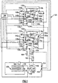
- FIG. 1 schematically illustrates a hot gas heat treatment system 120 not part of the invention.
- the system 120 includes a first hopper 122a and a second hopper 122b which each store a mix for making a frozen dessert product, such as soft service ice cream or a milkshake.
- the mix in the first hopper 122a and the mix in the second hopper 122b can be different flavors. That is, the mix in the first hopper 122a and the first freezing cylinder 124a can have one flavor, and the mix in the second hopper 122b and the second freezing cylinder 124b can have a different flavor.
- the hoppers 122a and 122b are each 20 quart hoppers.
- the mix in the first hopper 122a flows into a first freezing cylinder 124a, and the mix in the second hopper 122a flows into a second freezing cylinder 124b.
- the mix is frozen and mixed with air to form the frozen dessert product.
- a standard air-mix feed tube is used to meter the air into the freezing cylinders 124a and 124b.
- air is metered into the freezing cylinders 124a and 124b by a pump.
- the freezing cylinders 124a and 124b are each made of stainless steel.
- the frozen product is then dispensed from the freezing cylinders 124a and 124b for serving.
- the frozen product in the freezing cylinders 124a and 124b can also be twisted together to form a frozen dessert with two flavors.
- the hoppers 122a and 122b and the freezing cylinders 124a and 124b are cooled by a refrigeration system.
- Refrigerant flows through the closed circuit system.
- the refrigerant is R404A.
- the hot gas refrigerant is compressed in a compressor 126 to a high pressure and a high enthalpy.
- the compressor 126 can be a single speed, a two speed, or other variable speed compressor.
- the compressor 126 can also have variable displacement or capacity.
- the refrigerant then flows through a condenser 128 and rejects heat to a fluid medium.
- the refrigerant is cooled by a fan 130 driven by a motor 132.
- the condenser 128 is a three row 5/16 inch tube and raised lanced fin condenser.
- the condenser 128 can be either a water cooled condenser or an air cooled condenser. However, it is to be understood that other types of condensers 128 can be employed. Due to the high refrigeration loads during the heating mode, the capacity of the condenser 128 must be increased versus similar capacity non-heat treat configurations. The size of the compressor 126 and the size of the condenser 128 are balanced and related to each other.
- the refrigerant cooled by the condenser 128 is split into four paths 134a, 134b, 136a and 136b.
- the path 134a leads to the first freezing cylinder 124a
- the path 134b leads to the second freezing cylinder 124b
- the path 136a leads to the first hopper 122a
- the path 136b leads to the second hopper 122b.
- the refrigerant flowing along the path 134a passes through an expansion valve 138a and is expanded to a low pressure.
- the expansion valve 138a is an AXV expansion valve.
- An AXV expansion valve is an automatic expansion valve that constantly regulates pressure to control the evaporating pressure of the refrigerant flowing around the first freezing cylinder 124a at 0,24-0,25 MPa (20-22 psig), which corresponds to approximately -26°C (-15°F). Because the mix in the first freezing cylinder 124a is sensitive to the fixed evaporator temperature, this allows for consistent product quality. The mix in the first freezing cylinder 124a usually takes less time to cool than the mix in the first hopper 122a.
- the refrigerant flows through tubing encircling the first freezing cylinder 124a, accepting heat from and cooling the mix in the first freezing cylinder 124a.
- the refrigerant exits the tubing around the first freezing cylinder 124a through a path 144a.
- tubing has been described, it is to be understood that the refrigerant can also flow through a chamber that is proximate to the first freezing cylinder 124a.
- the refrigerant flowing along the path 136a passes through an expansion valve 140a and is expanded to a low pressure.
- the expansion valve 140a is a TXV expansion valve.
- a TXV expansion valve, or thermal expansion valve has a higher capacity for heat removal.
- the refrigeration capacity required to cool the first hopper 122a varies and is proportional to the mix level in the first hopper 122a.
- the TXV expansion valve 140a provides control of the refrigerant massflow to the first hopper 122a and maintains the set amount of superheat to assure compressor 126 reliability.
- the TXV expansion valve 140a attempts to maintain a superheat of 10°F.
- the TXV expansion valve 140a is controlled by a temperature sensing bulb 192a.
- the temperature sensing bulb 192a senses the temperature of the refrigerant exiting the first hopper 122a. Based on the value detected by the temperature sensing bulb 192a, the TXV expansion valve 140a controls the pressure, and therefore the temperature, of the refrigerant entering the first hopper 122a by controlling the amount of refrigerant that enters the first hopper 122a.
- the TXV expansion valve 140a is a pressuring limiting TXV expansion valve that regulates the suction pressure of the first hopper 122a to regulate the superheat out of the first hopper 122a.
- the refrigerant flows through tubing encircling the first hopper 122a, accepting heat from and cooling the mix in the first hopper 122a.
- the tubing encircling the first hopper 122a is a copper tube refrigeration line wrapped around and soldered to the bottom and the walls of the first hopper 122a and have a diameter of approximately 5/16 of an inch in diameter.
- the tubing can have other diameters or be made of other materials.
- the surface area of the refrigeration line soldered to the bottom of the first hopper 122a is maximized.
- the refrigerant that cools the mix in the first hopper 122a is between -5,6°C (22°F) and -4,4°C (24°F), keeping the mix in the first hopper 122a between: 2,8°C (37°F) and 3,9°C (39°F), below the standard of 5°C (41°F).
- the refrigerant exits the first hopper 122a through a path 142a.
- the refrigerant flowing along the path 134b passes through an expansion valve 138b and is expanded to a low pressure.
- the expansion valve 138b is an AXV expansion valve.
- An AXV expansion valve is an automatic expansion valve that constantly regulates pressure to control the evaporating pressure of the refrigerant flowing around the second freezing cylinder 124b at 20-22 psig, which corresponds to approximately -26°C (-15°F). Because the mix in the second freezing cylinder 124b is sensitive to the fixed evaporator temperature, this allows for consistent product quality. The mix in the second freezing cylinder 124b usually takes less time to cool than the mix in the hopper 122b.
- the refrigerant flows through tubing encircling the second freezing cylinder 124b, accepting heat from and cooling the mix in the second freezing cylinder 124b.
- the refrigerant exits the tubing around the second freezing cylinder 124b through a path 144b.
- tubing has been described, it is to be understood that the refrigerant can also flow through a chamber that is proximate to the second freezing cylinder 124b.
- the refrigerant flowing along the path 136b passes through an expansion valve 140b and is expanded to a low pressure.
- the expansion valve 140b is a TXV expansion valve.
- a TXV expansion valve, or thermal expansion valve has a higher capacity for heat removal.
- the refrigeration capacity required to cool the second hopper 122b varies and is proportional to the mix level in the second hopper 122b.
- the TXV expansion valve 140b provides control of the refrigerant massflow to the second hopper 122b and maintains the set amount of superheat to assure compressor 126 reliability.
- the TXV expansion valve 140b attempts to maintain a superheat of 10°F.
- the TXV expansion valve 140b is controlled by a temperature sensing bulb 192b.
- the temperature sensing bulb 192b senses the temperature of the refrigerant exiting the second hopper 122b. Based on the value detected by the temperature sensing bulb 192b, the TXV expansion valve 140b controls the pressure, and therefore the temperature, of the refrigerant entering the second hopper 122b by controlling the amount of refrigerant that enters the second hopper 122b.
- the TXV expansion valve 140b is a pressuring limiting TXV expansion valve that regulates the suction pressure of the second hopper 122b to regulate the superheat out of the second hopper 122b.
- the refrigerant flows through tubing encircling the second hopper 122b, accepting heat from and cooling the mix in the second hopper 122b.
- the tubing encircling the second hopper 122b is a copper tube refrigeration line wrapped around and soldered to the bottom and the walls of the second hopper 122b and have a diameter of approximately 5/16 of an inch in diameter.
- the tubing can have other diameters or be made of other materials.
- the surface area of the refrigeration line soldered to the bottom of the second hopper 122b is maximized.
- the refrigerant that cools the mix in the second hopper 122b is between 22° and 24°F (-5,6° and -4,4°C), keeping the mix in the second hopper 122b between 37° and 39°F (2,8 and 3,9°C), below the standard of 41°F(5°C).
- the refrigerant exits the second hopper 122b through a path 142b.
- the refrigerant After cooling the mix in the freezing cylinders 124a and 124b and the hoppers 122a and 122b, the refrigerant is at a low pressure and a high enthalpy.
- the refrigerant paths 142a, 142b, 144a and 144b merge and the refrigerant returns to the compressor 126 for compression, completing the cycle.
- the system 120 further includes a receiver 180 that stores excess refrigerant and controls the variable amount of free refrigerant in the system 120.
- a heat exchanger/sub-cooler 182 is employed to exchange heat between the gaseous refrigerant exiting the hoppers 122a and 122b and the freezing cylinders 124a and 124b and the liquid refrigerant flowing towards the expansion valves 138a, 138b, 140a and 140b to further increase capacity.
- the heat exchanger/sub-cooler 182 warms the suction gas entering the compressor 126, ensuring that only gaseous refrigerant, and not liquid refrigerant, enters the compressor 126 and increasing compressor 126 life.
- a filter/dryer 184 is employed to trap any debris in the refrigerant and to remove any water which may have leaked into the refrigeration system 120.
- the system 120 operates in a heating mode to heat treat the mix in the hoppers 122a and 122b and the freezing cylinders 124a and 124b.
- the system 120 further includes hot gas solenoid valves 150a, 150b, 152a and 152b that control the flow of refrigerant from the compressor discharge 158 to the freezing cylinders 124a and 124b and the hoppers 122a and 122b, respectively.
- the hot gas solenoid valves 150a, 150b, 152a and 152b are opened to allow hot gas refrigerant from the compressor discharge 158 of the compressor 126 to bypass the condenser 128 and flow around the hoppers 122a and 122b and the freezing cylinders 124a and 124b.
- the liquid line solenoid valves 146a, 146b, 148a and 148b are closed to prevent the cooled refrigerant from the condenser 128 from flowing to around the hoppers 122a and 122b and the freezing cylinders 124a and 124b.
- the mix is heated to at least 150°F (65°C) for at least 30 minutes every night to heat treat the mix and kill any bacteria.
- the refrigeration line is soldered to both the bottom and the walls of the hoppers 122a and 122b, increasing the surface area and reducing baking of the mix on the walls of the hoppers 122a and 122b.
- the mix bakes when a mix film clings to the walls of the hoppers 122a and 122b as the mix level drops.
- the hoppers 122a and 122b and the freezing cylinders 124a and 124b are heated separately, and therefore the mix can be both cooled and heated faster, reducing the time of the heat treatment cycle.
- the hot gas solenoid valves 152a and 152b are controlled separately and can be de-energized asynchronously. Temperatures sensors 172a, 172b, 174a and 174b provide temperature feedback from the freezing cylinders 124a and 124b and the hoppers 122a and 122b, respectively, to indicate when the mix has reached the desired temperature. The temperatures of the mix in the hoppers 122a and 122b and the freezing cylinders 124a and 124b are provided to a control 186 which controls the system 120.
- the liquid line solenoid valves 146a, 146b, 148a and 148b and the hot gas solenoid valves 150a, 150b, 152a and 152b are controlled separately by the control 186.
- the hoppers 122a and 122b and the freezing cylinders 124a and 124b can therefore be cooled and heated separately.
- a hot gas bypass valve 154 may be opened to allow hot refrigerant from the compressor discharge 158 to flow into the compressor suction 160, applying extra load to the compressor 126.
- the hot gas bypass valve 154 is self-regulated. The refrigerant gas is diverted from performing any refrigerant effect, but provides a load to the compressor 126 to maintain the suction pressure of the compressor 126 above 0,17 MPa (10 psig).
- the hot gas bypass valve 154 is closed at all other times. However, it is possible that the hot gas bypass valve 154 may not completely close, resulting in an undesirable leakage of refrigerant into the system 120.
- a hot gas bypass solenoid valve 156 can be employed in series with the hot gas bypass valve 154 to prevent undesirable leakage of refrigerant from the compressor discharge 158 into the system 120.
- the hot gas bypass solenoid valve 156 is activated in parallel with the liquid line solenoid valves 148a and 148b so that the hot gas bypass solenoid valve 156 only opens when the liquid line solenoid valves 148a and 148b are opened. Alternately, the hot gas bypass solenoid valve 156 is activated by the control 186.
- the hot gas bypass solenoid valve 156 is also opened with the hot gas bypass valve 154 to provide additional load on the compressor 126.
- the hot gas bypass solenoid valve 156 is closed at all other times to prevent the leakage of refrigerant from the compressor discharge 158 into the system 120.
- the system 120 further includes an evaporator pressure regulator valve, or an EPR valve 162a and 162b, positioned proximate to the discharge of each of the hoppers 122a and 122b, respectively.
- the EPR valves 162a and 162b are self-regulated.
- the refrigerant exchanging heat with the mix in the hoppers 122a and 122b and the freezing cylinders 124a and 124b is pumped from the same compressor 126.
- the refrigerant flowing around the hoppers 122a and 122b needs to be between -5,6 to -4,4°C (22° to 24°F) to cool the mix in the hoppers 122a and 122b to 2,8° to 3,9°C (37° to 39°F) and the refrigerant flowing around the freezing cylinders 124a and 124b needs to be about -26°C (-15°F) to cool the mix in the freezing cylinders 124a and 124b to -6,7°C (20°F).
- the EPR valves 162a and 162b maintain the pressure of the refrigerant exchanging heat with the mix in the hoppers 122a and 122b at 0,52 MPa (60 psig), and therefore maintain the temperature of the refrigerant flowing around the hoppers 122a and 122b at the desired temperature.
- a crankcase pressure regulator valve, or CPR valve 164 is employed to control the inlet pressure of the refrigerant entering the compressor 126 and to maintain the compressor suction pressure below 40 psig.
- the CPR valve 164 is also self-regulated. If the compressor suction pressure increases above 40 psig, the compressor 126 can stall.
- the CPR valve 164 is throttled or restricted to reduce the amount of hot refrigerant flowing into the compressor suction 160.
- the pressure of the refrigerant flowing into the compressor suction 160 decreases, and therefore the pressure of the refrigerant flowing through the compressor discharge 158 decreases.
- the CPR valve 164 can be eliminated if the orifices in the hot gas solenoid valves 150a, 150b, 152a and 152b are sized to adequately limit refrigeration flow.
- the system 120 further includes a liquid bypass valve or a temperature responsive expansion valve, or TREV valve 166, to adjust liquid refrigerant injection to the compressor suction 160 to control excessive compressor discharge temperature during the cooling mode.
- TREV valve 166 is also self-regulating.
- a TREV bulb 168 positioned proximate to the compressor discharge 158 senses the temperature of the refrigerant at the compressor discharge 158.
- the TREV bulb 168 is positioned proximate to the compressor suction 160 to monitor the suction temperature of the compressor 126.
- the TREV valve 166 and the TREV bulb 168 are connected by a capillary tube.
- the TREV valve 166 opens to allow the cool high pressure liquid refrigerant from the condenser 128 to flow into the compressor suction 160, cooling the compressor suction 160 and therefore the compressor discharge 158. Therefore, the compressor discharge 158 temperature can be kept below than 250°F (121°C).
- the system 120 further includes a pressure switch 194 at the compressor discharge 158.
- a pressure switch 194 at the compressor discharge 158. When the pressure of the refrigerant exiting the compressor 126 is greater than 440 psig (3,1 MPa), the compressor 126 shuts off.
- a suction solenoid valve 170a and 170b is located proximate to each of the discharge 188a of the first freezing cylinder 124a and the discharge 188b of the second freezing cylinder 124b, respectively.
- the suction solenoid valves 170a and 170b are closed to prevent refrigerant from migrating out of the freezing cylinders 124a and 124b.
- the hot gas solenoid valves 152a and 152b are first opened to heat the mix in the hoppers 122a and 122b first.
- the hot gas solenoid valves 150a and 150b are then opened to heat the mix in the freezing cylinders 124a and 124b.
- the hot gas solenoid valves 150a and 150b are opened after a set amount of time, for example after 10 minutes.
- the suction solenoid valves 170a and 170b are opened at the same time the hot gas solenoid valves 152a and 152b are opened to allow any refrigerant in the freezing cylinders 124a and 124b to boil off, preventing the refrigerant from flowing into and slugging the compressor 126.
- the hot gas solenoid valves 150a, 150b, 152a and 152b and the suction solenoid valves 170a and 170b are opened at the same time.
- the temperature sensors 172a, 172b, 174a and 174b detect the temperature of the mix in the freezing cylinders 124a and 124b and the hoppers 122a and 122b, respectively.
- the system 120 is activated and the cooling mode begins to cool the mix in the hoppers 122a and 122b to 2,8°C (37°F).
- the freezing cylinders 124a and 124b each further include a beater 176a and 176b, respectively.
- the beaters 176a and 176b are activated to stir the mix in the freezing cylinders 124a and 124b and equalize the product temperature.
- Agitators 178a and 178b also stir the mix in the respective hoppers 122a and 122b.
- the agitators 178a and 178b are an auto stepping motor assembly mounted to the bottom of the hoppers 122a and 122b and turn an agitator blade suspended in the mix.
- the temperature of the mix in the hoppers 122a and 122b is monitored by the temperature sensors 174a and 174b prior to shutting the compressor 126 off. If the temperature of the mix in the hoppers 122a and 122b is detected to be greater than 2,8°C (37°F), the cool refrigerant is sent to the hoppers 122a and 122b for cooling the mix.
- the mix in the hoppers 122a and 122b is cooled at this time because it is more efficient to cool the hoppers 122a and 122b while the system 120 is already operating in the cooling mode.
- the liquid line solenoid valves 146a, 146b, 148a and 148b, the hot gas solenoid valves 150a, 150b, 152a and 152b, the suction solenoid valves 170a and 170b, and the hot gas bypass solenoid valve 156 are all controlled by the control 186, which is the main control 186 of the system 120.
- the hot gas bypass valve 154, the EPR valves 162a and 162b, the CPR valve 164, the TREV valve 166, and the expansion valves 138a, 138b, 140a and 140b are self-regulated.
- the control 186 When the control 186 detects that it is necessary to cool the mix in one of the hoppers 122a and 122b and the freezing cylinders 124a and 124b, the control 186 activates the system 120 and opens the liquid line solenoid valves 146a, 146b, 148a and 148b. When the control 186 detects that it is necessary to heat the mix in one of the hoppers 122a and 122b and the freezing cylinders 124a and 124b, the control 186 activates the system 120 and opens the hot gas solenoid valves 150a, 150b, 152a and 152b and the suction solenoid valves 170a and 170b.
- the hoppers 122a and 122b and the freezing cylinders 124a and 124b can also be separately cooled and heated depending on system 120 requirements.
- the cooling mode is operated as needed when instructed by the control 186 to maintain the temperature of the mix in the hoppers 122a and 122b and the freezing cylinders 124a and 124b within the desired ranges.
- a switch is activated and refrigerant is immediately sent to the freezing cylinders 124a and 124b.
- the system 120 may be placed in a standby mode. The system 120 enters the stand-by mode either manually or after a programmed or manual heat cycle.
- the product in the freezing cylinders 124a and 124b is allowed to melt.
- the mix in the freezing cylinders 124a and 124b is warmed to the temperature of the mix in the hoppers 122a and 122b, reducing the amount of churning, which can ruin the product quality.
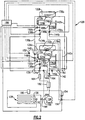
- FIG. 2 illustrates an embodiment of the system 120 of the present invention.
- a TXV expansion valve 140 and liquid line solenoid valve 148 control the flow of liquid refrigerant into both of the hoppers 122a and 122b.
- a hot gas solenoid valve 152 controls the flow of hot gaseous refrigerant from the compressor discharge 158 to the hoppers 122a and 122b.
- An evaporator pressure regulator valve, or an EPR valve 162 is positioned proximate to the discharge of the hoppers 122a and 122b.
- the refrigerant exits the hoppers 122a and 122b through the paths 142a and 142b, respectively.
- the paths 142a and 142b merge into a path 142, and the EPR valve 162 is located on the path 142.
- TXV expansion valves 140a and 140b of Figure 1 are combined into a single TXV expansion valve 140, the liquid line solenoid valves 148a and 148b of Figure 1 are combined into a single liquid line solenoid valve 148, the hot gas solenoid valves 152a and 152b of Figure 1 are combined into a single hot gas solenoid valve 152, and the EPR valves 162a and 162b of Figure 1 are combined into a single EPR valve 162.
- the TXV expansion valve 140 is controlled by a temperature sensing bulb 192.
- the temperature sensing bulb 192 detects the temperature of the refrigerant exiting the hoppers 122a and 122b.
- the TXV expansion valve 140 controls the temperature of the refrigerant entering the hoppers 122a and 122b by controlling the amount of refrigerant that enters the hoppers 122a and 122b based on the value detected by the temperature sensing bulb 192.
- the expansion valve 140 and the liquid line solenoid valve 148 are opened and the hot gas solenoid valve 152 is closed.
- the refrigerant from the compressor 126 is cooled in the condenser 128 and flows along the path 136.
- the path 136 splits into a path 136a that flows to the first hopper 122a and a path 136b that flows to the second hopper 122b to cool the mix in the hoppers 122a and 122b.
- the expansion valve 140 and the liquid line solenoid valve 148 are closed and the hot gas solenoid valve 152 is open.
- the refrigerant from the compressor discharge 158 of the compressor 126 flows along a path 136a that flows to the first hopper 122a and a path 136b that flows to the second hopper 122b to heat the mix in the hoppers 122a and 122b.
- FIG 3 illustrates another embodiment of the system 120 of the present invention.
- the system 120 includes pulse width modulated valves or stepper valves rather than the AXV valves/solenoid valve, TXV valves/solenoid valves of Figures 1 and 2 and eliminating the need for solenoid valves.
- a PWM valve 137a controls the flow of the refrigerant entering the first freezing cylinder 124a
- a PWM valve 137b controls the flow of the refrigerant entering the second freezing cylinder
- a PWM valve 139 controls the flow of the refrigerant entering both the hoppers 122a and 122b.
- a PWM valve 141a controls the flow of hot gas refrigerant from the compressor 126 and entering the first freezing cylinder 124a
- a PWM valve 141b controls the flow of hot gas refrigerant from the compressor 126 and entering the second freezing cylinder 124b
- a PWM valve 143 controls the flow of hot gas refrigerant from the compressor 126 and entering both the hoppers 122a and 122b.
- the system 120 further includes pressure or temperature transducers 145a and 145b at the inlet of the freezing cylinders 124a and 124b, respectively, pressure or temperatures transducers 147a and 147b at the outlet of the freezing cylinders 124a and 124b, respectively, a pressure or temperature transducer 149 on the line leading to the inlets of the hoppers 122a and 122b and a pressure or temperature transducer 151 on the line leading from the outlets of the hoppers 122a and 122b.
- Refrigerant flow through the PWM valves 137a, 137b, 139, 141a, 141b and 143 is based on the values detected by the transducers 145a, 145b, 147a, 147b, 149 and 151. That is, refrigerant flow is adjusted as a function of pressure or superheat.
- An evaporator pressure regulator valve, or an EPR valve 162 is positioned proximate to the discharge of the hoppers 122a and 122b.
- the refrigerant exits the hoppers 122a and 122b through the paths 142a and 142b, respectively.
- the paths 142a and 142b merge into a path 142, and the EPR valve 162 is located on the path 142.
- the PWM valves 137a, 137b and 139 are modulated and the PWM valves 141a, 141b and 142 are closed.
- the refrigerant from the compressor 126 is cooled by the condenser 128 cools the mix in the hoppers 122a and 122b and freezing cylinders 124a and 124b.
- the PWM valves 137a, 137b and 139 are closed and the PWM valves 141a, 141b and 142 are modulated.
- the refrigerant from the compressor 126 heats the mix in the hoppers 122a and 122b and the freezing cylinders 124a and 124b.
- first hopper 122a and a first freezing cylinder 124a for a mix and a second hopper 124a and a second freezing cylinder 124b for another mix have been illustrated and described, it is to be understood that the system 120 can include any number of hoppers and freezing cylinders. Each hopper and freezing cylinder pair can be used for a different flavor of frozen dessert.
Landscapes
- Engineering & Computer Science (AREA)
- Life Sciences & Earth Sciences (AREA)
- Chemical & Material Sciences (AREA)
- Food Science & Technology (AREA)
- Polymers & Plastics (AREA)
- Physics & Mathematics (AREA)
- Mechanical Engineering (AREA)
- Thermal Sciences (AREA)
- General Engineering & Computer Science (AREA)
- Manufacturing & Machinery (AREA)
- Confectionery (AREA)
Description
- The present invention relates generally a hot gas heat treatment system used in a frozen dessert system to cool frozen dessert mix for serving and to heat the frozen dessert mix during heat treatment. More specifically, the present invention relates to a frozen dessert system including more than one hopper and more than one freezing cylinder.
- A refrigeration system is employed to cool a mix in a frozen dessert system. The frozen dessert system typically includes a hopper which stores the mix and a freezing cylinder that cools and adds air into the mix prior to serving. The freezing cylinder is cooled by a refrigeration system. Refrigerant is compressed in a compressor to a high pressure and a high enthalpy. The refrigerant flows through a condenser and rejects heat to a fluid medium and is cooled. The high pressure and low enthalpy refrigerant is then expanded to a low pressure. The refrigerant flows through tubing encircling the freezing cylinder and cools the mix in the freezing cylinder. The low pressure and high enthalpy refrigerant returns to the compressor, completing the cycle.
- The hopper is cooled by a separate glycol system including tubes that wrap around both the hopper and the freezing cylinder. The glycol first flows around the freezing cylinder and is cooled. The cooled glycol then flows around the hopper to cool the mix in the hopper. To meet food safety standards, the mix in the hopper is generally maintained below 5°C (41°F).
- The mix is heat treated every night to kill any bacteria. The mix is heated for approximately 90 minutes to a temperature of at least 65°C (150°F). The mix is maintained at a temperature over 65°C (150°F) for 30 minutes and then cooled to 5°C (41°F) within 120 minutes. The mix is heated by heating the glycol with an electrical resistance heater or a gas burner. The heated glycol flows around the hopper and the freezing cylinder to heat the mix.
- A drawback to this system is that the freezing cylinder and the hopper are coupled by the glycol system. When the cooled glycol flows around the hopper during cooling, the glycol is heated. The heated glycol then flows around the freezing cylinder, which can melt the mix in the freezing cylinder.
- During heat treatment, the glycol first heats the mix in the freezing cylinder. The glycol is cooled and therefore less effective in heating the mix in the hopper. It takes longer to heat the mix in the hopper, possibly increasing the length of the heat treatment cycle to over three hours. The heat treatment cycle can change the flavor of the mix, and a longer heat treatment cycle can negatively affect the flavor of the frozen dessert.
- In prior hot gas heat treatment systems, the mix in the hopper and the freezing cylinder cannot be separately cooled. If one of the hopper and the freezing cylinder required cooling, the other has to be cooled as well. The suction lines of the hopper and the freezing cylinder of the prior art system are coupled, and therefore it is difficult to vary the pressure, and hence the temperature, of the refrigerant flowing around the hopper and the freezing cylinder. It is preferably for the refrigerant cooling the mix in the hopper to have a different temperature and pressure than the refrigerant freezing the mix in the freezing cylinder. Another drawback of the prior art hot gas heat treatment system is that the system has a low capacity, and therefore the compressor is undersized to attain compressor reliability.
- A refrigeration system in which two systems each comprising a hopper and freezing cylinder share a compressor is disclosed in
US 2004/0079095 A1 . A refrigeration system according to the preamble of claim 1 is known fromUS 5 159 818 A . - The present invention provides a refrigeration system as set forth in claim 1.
- The disclosed hot gas heat treat system includes a first hopper and a second hopper which each store a mix for forming a frozen product. The mix from the first hopper and the second hopper flow into a first freezing cylinder and a second freezing cylinder, respectively, for cooling and mixing with air to form a frozen dessert. The mix in the first hopper and the first freezing cylinder can have a first flavor, and the mix in the second hopper and the second freezing cylinder can have a second flavor.
- Refrigerant is compressed in a compressor and then cooled by a condenser. The liquid refrigerant is then split into four paths, and one path flows to each of the hoppers and freezing cylinders. The refrigerant flowing to the freezing cylinders is expanded to a low pressure by an AXV expansion valve and cools the mix in the freezing cylinders. The refrigerant flowing to the hoppers is expanded to a low pressure by a TXV expansion valve and cools the mix in the hoppers. After cooling the mix in the freezing cylinders and the hoppers, the refrigerant is at a low pressure and high enthalpy. The refrigerant paths merge, and the refrigerant returns to the compressor for compression.
- A liquid line solenoid valve is positioned before each of the expansion valves proximate to the inlets of the hoppers and the freezing cylinder to control the flow of cool high pressure liquid refrigerant from the condenser. A hot gas solenoid valve is also positioned at each of the inlets of the hoppers and the freezing cylinders to control flow of hot gaseous refrigerant from the compressor. When the system is operating in a cooling mode, the liquid line solenoid valves are opened and the hot gas solenoid valves are closed to allow the flow of cool liquid refrigerant from the condenser into the hoppers and the freezing cylinders to cool the mix. When the system is operating in a heating mode for nightly heat treatment, the hot gas solenoid valves are opened and the liquid line solenoid valves are closed to allow the flow of hot refrigerant from the compressor into the hoppers and the freezing cylinders to heat the mix.
- The system further includes a hot gas bypass valve to allow refrigerant gas from the compressor discharge to flow to the compressor suction to increase compressor load. An EPR valve is positioned proximate to each of the hopper discharges to maintain the evaporator pressure, and therefore the temperature, of the refrigerant flowing through the hoppers. The system includes a CPR valve to limit the inlet pressure of the compressor by reducing the amount of refrigerant flowing into the compressor suction. The system also includes a TREV valve that allows the high pressure liquid refrigerant from the condenser to flow into the compressor suction to cool both the compressor suction and discharge.
- These and other features of the present invention will be best understood from the following specification and drawings.
- The various features and advantages of the invention will become apparent to those skilled in the art from the following detailed description of the currently preferred embodiment. The drawing that accompany the detailed description can be briefly described as follows:
-
Figure 1 schematically illustrates a first example of the hot gas heat treatment system not part of the claimed invention; -
Figure 2 schematically illustrates an embodiment of the hot gas heat treatment system of the present invention; and -
Figure 3 schematically illustrates another embodiment of the hot gas heat treatment system of the present invention; -
Figure 1 schematically illustrates a hot gasheat treatment system 120 not part of the invention. Thesystem 120 includes afirst hopper 122a and asecond hopper 122b which each store a mix for making a frozen dessert product, such as soft service ice cream or a milkshake. The mix in thefirst hopper 122a and the mix in thesecond hopper 122b can be different flavors. That is, the mix in thefirst hopper 122a and the first freezingcylinder 124a can have one flavor, and the mix in thesecond hopper 122b and the second freezingcylinder 124b can have a different flavor. - In one example, the
hoppers first hopper 122a flows into a first freezingcylinder 124a, and the mix in thesecond hopper 122a flows into asecond freezing cylinder 124b. In the freezingcylinders - In a gravity fed system, a standard air-mix feed tube is used to meter the air into the freezing
cylinders cylinders cylinders cylinders cylinders - The
hoppers cylinders compressor 126 to a high pressure and a high enthalpy. Thecompressor 126 can be a single speed, a two speed, or other variable speed compressor. Thecompressor 126 can also have variable displacement or capacity. The refrigerant then flows through acondenser 128 and rejects heat to a fluid medium. The refrigerant is cooled by afan 130 driven by amotor 132. In one example, thecondenser 128 is a three row 5/16 inch tube and raised lanced fin condenser. Thecondenser 128 can be either a water cooled condenser or an air cooled condenser. However, it is to be understood that other types ofcondensers 128 can be employed. Due to the high refrigeration loads during the heating mode, the capacity of thecondenser 128 must be increased versus similar capacity non-heat treat configurations. The size of thecompressor 126 and the size of thecondenser 128 are balanced and related to each other. - The refrigerant cooled by the
condenser 128 is split into fourpaths path 134a leads to the first freezingcylinder 124a, thepath 134b leads to the second freezingcylinder 124b, thepath 136a leads to thefirst hopper 122a, and thepath 136b leads to thesecond hopper 122b. - The refrigerant flowing along the
path 134a passes through anexpansion valve 138a and is expanded to a low pressure. Preferably, theexpansion valve 138a is an AXV expansion valve. An AXV expansion valve is an automatic expansion valve that constantly regulates pressure to control the evaporating pressure of the refrigerant flowing around the first freezingcylinder 124a at 0,24-0,25 MPa (20-22 psig), which corresponds to approximately -26°C (-15°F). Because the mix in the first freezingcylinder 124a is sensitive to the fixed evaporator temperature, this allows for consistent product quality. The mix in the first freezingcylinder 124a usually takes less time to cool than the mix in thefirst hopper 122a. Although an AXV expansion valve has been described, it is to be understood that other types of expansion valve can be employed. - After expansion, the refrigerant flows through tubing encircling the first freezing
cylinder 124a, accepting heat from and cooling the mix in the first freezingcylinder 124a. The refrigerant exits the tubing around the first freezingcylinder 124a through apath 144a. Although tubing has been described, it is to be understood that the refrigerant can also flow through a chamber that is proximate to the first freezingcylinder 124a. - The refrigerant flowing along the
path 136a passes through anexpansion valve 140a and is expanded to a low pressure. Preferably, theexpansion valve 140a is a TXV expansion valve. A TXV expansion valve, or thermal expansion valve, has a higher capacity for heat removal. The refrigeration capacity required to cool thefirst hopper 122a varies and is proportional to the mix level in thefirst hopper 122a. TheTXV expansion valve 140a provides control of the refrigerant massflow to thefirst hopper 122a and maintains the set amount of superheat to assurecompressor 126 reliability. TheTXV expansion valve 140a attempts to maintain a superheat of 10°F. - The
TXV expansion valve 140a is controlled by atemperature sensing bulb 192a. Thetemperature sensing bulb 192a senses the temperature of the refrigerant exiting thefirst hopper 122a. Based on the value detected by thetemperature sensing bulb 192a, theTXV expansion valve 140a controls the pressure, and therefore the temperature, of the refrigerant entering thefirst hopper 122a by controlling the amount of refrigerant that enters thefirst hopper 122a. In this example, theTXV expansion valve 140a is a pressuring limiting TXV expansion valve that regulates the suction pressure of thefirst hopper 122a to regulate the superheat out of thefirst hopper 122a. - After expansion, the refrigerant flows through tubing encircling the
first hopper 122a, accepting heat from and cooling the mix in thefirst hopper 122a. In one example, the tubing encircling thefirst hopper 122a is a copper tube refrigeration line wrapped around and soldered to the bottom and the walls of thefirst hopper 122a and have a diameter of approximately 5/16 of an inch in diameter. However, it is to be understood that the tubing can have other diameters or be made of other materials. Preferably, the surface area of the refrigeration line soldered to the bottom of thefirst hopper 122a is maximized. Preferably, the refrigerant that cools the mix in thefirst hopper 122a is between -5,6°C (22°F) and -4,4°C (24°F), keeping the mix in thefirst hopper 122a between: 2,8°C (37°F) and 3,9°C (39°F), below the standard of 5°C (41°F). The refrigerant exits thefirst hopper 122a through apath 142a. - The refrigerant flowing along the
path 134b passes through anexpansion valve 138b and is expanded to a low pressure. Preferably, theexpansion valve 138b is an AXV expansion valve. An AXV expansion valve is an automatic expansion valve that constantly regulates pressure to control the evaporating pressure of the refrigerant flowing around the second freezingcylinder 124b at 20-22 psig, which corresponds to approximately -26°C (-15°F). Because the mix in the second freezingcylinder 124b is sensitive to the fixed evaporator temperature, this allows for consistent product quality. The mix in the second freezingcylinder 124b usually takes less time to cool than the mix in thehopper 122b. Although an AXV expansion valve has been described, it is to be understood that other types of expansion valve can be employed. - After expansion, the refrigerant flows through tubing encircling the second freezing
cylinder 124b, accepting heat from and cooling the mix in the second freezingcylinder 124b. The refrigerant exits the tubing around the second freezingcylinder 124b through apath 144b. Although tubing has been described, it is to be understood that the refrigerant can also flow through a chamber that is proximate to the second freezingcylinder 124b. - The refrigerant flowing along the
path 136b passes through anexpansion valve 140b and is expanded to a low pressure. Preferably, theexpansion valve 140b is a TXV expansion valve. A TXV expansion valve, or thermal expansion valve, has a higher capacity for heat removal. The refrigeration capacity required to cool thesecond hopper 122b varies and is proportional to the mix level in thesecond hopper 122b. TheTXV expansion valve 140b provides control of the refrigerant massflow to thesecond hopper 122b and maintains the set amount of superheat to assurecompressor 126 reliability. TheTXV expansion valve 140b attempts to maintain a superheat of 10°F. - The
TXV expansion valve 140b is controlled by atemperature sensing bulb 192b. Thetemperature sensing bulb 192b senses the temperature of the refrigerant exiting thesecond hopper 122b. Based on the value detected by thetemperature sensing bulb 192b, theTXV expansion valve 140b controls the pressure, and therefore the temperature, of the refrigerant entering thesecond hopper 122b by controlling the amount of refrigerant that enters thesecond hopper 122b. In this example, theTXV expansion valve 140b is a pressuring limiting TXV expansion valve that regulates the suction pressure of thesecond hopper 122b to regulate the superheat out of thesecond hopper 122b. - After expansion, the refrigerant flows through tubing encircling the
second hopper 122b, accepting heat from and cooling the mix in thesecond hopper 122b. In one example, the tubing encircling thesecond hopper 122b is a copper tube refrigeration line wrapped around and soldered to the bottom and the walls of thesecond hopper 122b and have a diameter of approximately 5/16 of an inch in diameter. However, it is to be understood that the tubing can have other diameters or be made of other materials. Preferably, the surface area of the refrigeration line soldered to the bottom of thesecond hopper 122b is maximized. Preferably, the refrigerant that cools the mix in thesecond hopper 122b is between 22° and 24°F (-5,6° and -4,4°C), keeping the mix in thesecond hopper 122b between 37° and 39°F (2,8 and 3,9°C), below the standard of 41°F(5°C). The refrigerant exits thesecond hopper 122b through apath 142b. - After cooling the mix in the freezing
cylinders hoppers refrigerant paths compressor 126 for compression, completing the cycle. - The
system 120 further includes areceiver 180 that stores excess refrigerant and controls the variable amount of free refrigerant in thesystem 120. A heat exchanger/sub-cooler 182 is employed to exchange heat between the gaseous refrigerant exiting thehoppers cylinders expansion valves sub-cooler 182 warms the suction gas entering thecompressor 126, ensuring that only gaseous refrigerant, and not liquid refrigerant, enters thecompressor 126 and increasingcompressor 126 life. A filter/dryer 184 is employed to trap any debris in the refrigerant and to remove any water which may have leaked into therefrigeration system 120. - The
system 120 operates in a heating mode to heat treat the mix in thehoppers cylinders system 120 further includes hotgas solenoid valves compressor discharge 158 to the freezingcylinders hoppers gas solenoid valves compressor discharge 158 of thecompressor 126 to bypass thecondenser 128 and flow around thehoppers cylinders line solenoid valves condenser 128 from flowing to around thehoppers cylinders - The mix is heated to at least 150°F (65°C) for at least 30 minutes every night to heat treat the mix and kill any bacteria. The refrigeration line is soldered to both the bottom and the walls of the
hoppers hoppers hoppers hoppers cylinders - During the heating mode, it is preferable to first open the hot
gas solenoid valves hoppers gas solenoid valves cylinders compressor 126 flood back. The hotgas solenoid valves Temperatures sensors cylinders hoppers hoppers cylinders control 186 which controls thesystem 120. - The liquid
line solenoid valves gas solenoid valves control 186. Thehoppers cylinders - When only the
hoppers compressor 126, reducing the suction pressure of thecompressor 126 and affectingcompressor 126 reliability. When only thehoppers line solenoid valves line solenoid valves 148a and 148b are opened. A hotgas bypass valve 154 may be opened to allow hot refrigerant from thecompressor discharge 158 to flow into thecompressor suction 160, applying extra load to thecompressor 126. The hotgas bypass valve 154 is self-regulated. The refrigerant gas is diverted from performing any refrigerant effect, but provides a load to thecompressor 126 to maintain the suction pressure of thecompressor 126 above 0,17 MPa (10 psig). - The hot
gas bypass valve 154 is closed at all other times. However, it is possible that the hotgas bypass valve 154 may not completely close, resulting in an undesirable leakage of refrigerant into thesystem 120. A hot gasbypass solenoid valve 156 can be employed in series with the hotgas bypass valve 154 to prevent undesirable leakage of refrigerant from thecompressor discharge 158 into thesystem 120. - The hot gas
bypass solenoid valve 156 is activated in parallel with the liquidline solenoid valves 148a and 148b so that the hot gasbypass solenoid valve 156 only opens when the liquidline solenoid valves 148a and 148b are opened. Alternately, the hot gasbypass solenoid valve 156 is activated by thecontrol 186. When thecontrol 186 determines that the liquidline solenoid valves 148a and 148b for thehoppers line solenoid valves cylinders hoppers bypass solenoid valve 156 is also opened with the hotgas bypass valve 154 to provide additional load on thecompressor 126. The hot gasbypass solenoid valve 156 is closed at all other times to prevent the leakage of refrigerant from thecompressor discharge 158 into thesystem 120. - The
system 120 further includes an evaporator pressure regulator valve, or anEPR valve hoppers EPR valves hoppers cylinders same compressor 126. However, the refrigerant flowing around thehoppers hoppers cylinders cylinders EPR valves hoppers hoppers - A crankcase pressure regulator valve, or
CPR valve 164, is employed to control the inlet pressure of the refrigerant entering thecompressor 126 and to maintain the compressor suction pressure below 40 psig. TheCPR valve 164 is also self-regulated. If the compressor suction pressure increases above 40 psig, thecompressor 126 can stall. TheCPR valve 164 is throttled or restricted to reduce the amount of hot refrigerant flowing into thecompressor suction 160. The pressure of the refrigerant flowing into thecompressor suction 160 decreases, and therefore the pressure of the refrigerant flowing through thecompressor discharge 158 decreases. Alternately, theCPR valve 164 can be eliminated if the orifices in the hotgas solenoid valves - The
system 120 further includes a liquid bypass valve or a temperature responsive expansion valve, orTREV valve 166, to adjust liquid refrigerant injection to thecompressor suction 160 to control excessive compressor discharge temperature during the cooling mode. TheTREV valve 166 is also self-regulating. ATREV bulb 168 positioned proximate to thecompressor discharge 158 senses the temperature of the refrigerant at thecompressor discharge 158. Alternately, theTREV bulb 168 is positioned proximate to thecompressor suction 160 to monitor the suction temperature of thecompressor 126. In one example, theTREV valve 166 and theTREV bulb 168 are connected by a capillary tube. When theTREV bulb 168 detects that the discharge temperature of the refrigerant approaches 110°C (230°F), theTREV valve 166 opens to allow the cool high pressure liquid refrigerant from thecondenser 128 to flow into thecompressor suction 160, cooling thecompressor suction 160 and therefore thecompressor discharge 158. Therefore, thecompressor discharge 158 temperature can be kept below than 250°F (121°C). - The
system 120 further includes apressure switch 194 at thecompressor discharge 158. When the pressure of the refrigerant exiting thecompressor 126 is greater than 440 psig (3,1 MPa), thecompressor 126 shuts off. - A
suction solenoid valve cylinder 124a and thedischarge 188b of the second freezingcylinder 124b, respectively. When only thehoppers 122 and 122b are being cooled, thesuction solenoid valves cylinders - During the heating mode, the hot
gas solenoid valves hoppers gas solenoid valves cylinders gas solenoid valves suction solenoid valves gas solenoid valves cylinders compressor 126. Alternately, the hotgas solenoid valves suction solenoid valves - The
temperature sensors cylinders hoppers system 120 is inactive and thetemperature sensors 174a and 174b detect that the temperature of the mix in thehoppers system 120 is activated and the cooling mode begins to cool the mix in thehoppers cylinders beater cylinders beaters cylinders Agitators respective hoppers agitators hoppers - If the
system 120 is activated to cool the mix in the freezingcylinders hoppers temperature sensors 174a and 174b prior to shutting thecompressor 126 off. If the temperature of the mix in thehoppers hoppers hoppers hoppers hoppers system 120 is already operating in the cooling mode. - The liquid
line solenoid valves gas solenoid valves suction solenoid valves bypass solenoid valve 156 are all controlled by thecontrol 186, which is themain control 186 of thesystem 120. The hotgas bypass valve 154, theEPR valves CPR valve 164, theTREV valve 166, and theexpansion valves control 186 detects that it is necessary to cool the mix in one of thehoppers cylinders control 186 activates thesystem 120 and opens the liquidline solenoid valves control 186 detects that it is necessary to heat the mix in one of thehoppers cylinders control 186 activates thesystem 120 and opens the hotgas solenoid valves suction solenoid valves hoppers cylinders system 120 requirements. - When the
system 120 is operating in an automatic mode, the cooling mode is operated as needed when instructed by thecontrol 186 to maintain the temperature of the mix in thehoppers cylinders cylinders cylinders cylinders system 120 may be placed in a standby mode. Thesystem 120 enters the stand-by mode either manually or after a programmed or manual heat cycle. When the standby mode is activated, the product in the freezingcylinders cylinders hoppers -
Figure 2 illustrates an embodiment of thesystem 120 of the present invention. ATXV expansion valve 140 and liquidline solenoid valve 148 control the flow of liquid refrigerant into both of thehoppers gas solenoid valve 152 controls the flow of hot gaseous refrigerant from thecompressor discharge 158 to thehoppers EPR valve 162, is positioned proximate to the discharge of thehoppers hoppers paths paths path 142, and theEPR valve 162 is located on thepath 142. - The
TXV expansion valves Figure 1 are combined into a singleTXV expansion valve 140, the liquidline solenoid valves 148a and 148b ofFigure 1 are combined into a single liquidline solenoid valve 148, the hotgas solenoid valves Figure 1 are combined into a single hotgas solenoid valve 152, and theEPR valves Figure 1 are combined into asingle EPR valve 162. - The
TXV expansion valve 140 is controlled by atemperature sensing bulb 192. Thetemperature sensing bulb 192 detects the temperature of the refrigerant exiting thehoppers TXV expansion valve 140 controls the temperature of the refrigerant entering thehoppers hoppers temperature sensing bulb 192. - During the cooling mode, the
expansion valve 140 and the liquidline solenoid valve 148 are opened and the hotgas solenoid valve 152 is closed. The refrigerant from thecompressor 126 is cooled in thecondenser 128 and flows along thepath 136. Thepath 136 splits into apath 136a that flows to thefirst hopper 122a and apath 136b that flows to thesecond hopper 122b to cool the mix in thehoppers - During the heating mode, the
expansion valve 140 and the liquidline solenoid valve 148 are closed and the hotgas solenoid valve 152 is open. The refrigerant from thecompressor discharge 158 of thecompressor 126 flows along apath 136a that flows to thefirst hopper 122a and apath 136b that flows to thesecond hopper 122b to heat the mix in thehoppers -
Figure 3 illustrates another embodiment of thesystem 120 of the present invention. Thesystem 120 includes pulse width modulated valves or stepper valves rather than the AXV valves/solenoid valve, TXV valves/solenoid valves ofFigures 1 and2 and eliminating the need for solenoid valves. APWM valve 137a controls the flow of the refrigerant entering the first freezingcylinder 124a, aPWM valve 137b controls the flow of the refrigerant entering the second freezing cylinder, and aPWM valve 139 controls the flow of the refrigerant entering both thehoppers PWM valve 141a controls the flow of hot gas refrigerant from thecompressor 126 and entering the first freezingcylinder 124a, aPWM valve 141b controls the flow of hot gas refrigerant from thecompressor 126 and entering the second freezingcylinder 124b, and aPWM valve 143 controls the flow of hot gas refrigerant from thecompressor 126 and entering both thehoppers - The
system 120 further includes pressure ortemperature transducers cylinders temperatures transducers cylinders temperature transducer 149 on the line leading to the inlets of thehoppers temperature transducer 151 on the line leading from the outlets of thehoppers PWM valves transducers - An evaporator pressure regulator valve, or an
EPR valve 162, is positioned proximate to the discharge of thehoppers hoppers paths paths path 142, and theEPR valve 162 is located on thepath 142. - During the cooling mode, the
PWM valves PWM valves compressor 126 is cooled by thecondenser 128 cools the mix in thehoppers cylinders - During the heating mode, the
PWM valves PWM valves compressor 126 heats the mix in thehoppers cylinders - Although a
first hopper 122a and a first freezingcylinder 124a for a mix and asecond hopper 124a and asecond freezing cylinder 124b for another mix have been illustrated and described, it is to be understood that thesystem 120 can include any number of hoppers and freezing cylinders. Each hopper and freezing cylinder pair can be used for a different flavor of frozen dessert.
Claims (17)
- A refrigeration system comprising:a first hopper (122a) heat exchanger and a second hopper (122b) heat exchanger each configured to store a respective first and second mix for making a frozen dessert product;a compression device (126) to compress a refrigerant to a high pressure, said compression device (126) including a compressor suction and a compressor discharge;a heat rejecting heat exchanger (128) for cooling said refrigerant;a first cylinder expansion device (138a; 137a) for expanding a first portion of said refrigerant from said heat rejecting heat exchanger (128) to a first cylinder low pressure;a first cylinder (124a) heat exchanger, said first portion of said refrigerant from said first cylinder expansion device (138a; 137a) exchanging heat with a first mix in said first cylinder (124a) heat exchanger;a second cylinder expansion device (138b; 137b) for expanding a third portion of said refrigerant from said heat rejecting heat exchanger (128) to a second cylinder low pressure; anda second cylinder (124b) heat exchanger, a portion of said third portion of said refrigerant from said second cylinder expansion device (138b; 137b) exchanging heat with a second mix in said second cylinder (124b) heat exhanger, characterized in that it further comprisesa hopper expansion device (140) for expanding a second portion of said refrigerant from said heat rejecting heat exchanger (128) to a hopper low pressure, the hopper expansion device configured to control the flow of the second portion of said refrigeration into the first and second hoppers (122a, 122b);wherein said second portion of said refrigerant from said hopper expansion device (140) exchanges heat with said first mix in said first hopper (122a) heat exchanger and also exchanges heat with said second mix in said second hopper (122b).
- The system as recited in claim 1 further comprising a hopper liquid line solenoid valve (148) positioned between said hopper expansion device (140) and said heat rejecting heat exchanger (128), a first cylinder liquid line solenoid valve (146a) positioned between said first cylinder expansion device (138a) and said heat rejecting heat exchanger (128), and a second cylinder liquid line solenoid valve (146b) positioned between said second cylinder expansion device (138b) and said heat rejecting heat exchanger (128).
- The system as recited in claim 2 further comprising a hopper hot gas solenoid valve (152) positioned between said compressor discharge and said first hopper (122a) heat exchanger and additionally positioned between said compressor discharge and said second hopper (122b) heat exchanger, a first cylinder hot gas solenoid valve (150a) positioned between said compressor discharge and said first cylinder (122a) heat exchanger, and a second cylinder hot gas solenoid valve (150b) positioned between said compressor discharge and said second cylinder (122b) heat exchanger.
- The system as recited in claim 3 wherein said hopper liquid line solenoid valve (152), said first cylinder liquid line solenoid valve (146a), said hopper liquid line solenoid valve (148), and said second cylinder liquid line solenoid valve (146b) are open and said hopper hot gas solenoid valve (152), said first cylinder hot gas solenoid valve (150a), and said second cylinder hot gas solenoid valve (150b) are closed to allow refrigerant from said heat rejecting heat exchanger (128) to cool said first mix in said first hopper (122a) heat exchanger and said first cylinder (124a) heat exchanger and to cool said second mix in said second hopper (122b) heat exchanger and said second cylinder (124b) heat exchanger.
- The system as recited in claim 3 wherein said hopper liquid line solenoid valve (148), said first cylinder liquid line solenoid valve (146a), and said second cylinder liquid line solenoid valve (146b) are closed and said hopper hot gas solenoid valve (152), said first cylinder hot gas solenoid valve (150a), and said second cylinder hot gas solenoid valve (150b) are open to allow refrigerant from said compressor (128) discharge of said compressor to heat first mix in said first hopper (122a) heat exchanger and said first cylinder (124a) heat exchanger and to heat said second mix in said second hopper (122b) heat exchanger and said second cylinder (124b) heat exchanger.
- The system as recited in claim 3 further including a hot gas bypass valve (154) positioned between said compressor discharge and said compressor suction, and said hot gas bypass valve is opened to increase refrigerant flow from said compressor discharge to said compressor suction when said hopper liquid line solenoid valve (148) is opened, and said first cylinder liquid line solenoid valve (146a), said second cylinder liquid line solenoid valve (146b), said hopper hot gas solenoid valve (152), said first cylinder hot gas solenoid valve (150a) and said second cylinder hot gas solenoid valves (150b) are closed.
- The system as recited in claim 6 further including a hot gas bypass solenoid valve (156) in series with said hot gas bypass valve (154) and activated in parallel with said hopper liquid line solenoid valve (148), and said hot gas bypass solenoid valve (156) is opened when said hopper liquid line solenoid valve (148) is opened.
- The system as recited in claim 3 further including a first suction solenoid valve (170a) positioned proximate to a first cylinder discharge of said first cylinder (124a) heat exchanger and a second suction solenoid valve (170b) positioned proximate to a second cylinder discharge of said second cylinder (124b) heat exchanger, and said first suction solenoid valve (170a) and said second suction solenoid valve (170b) are closed when said system is inactive to prevent said refrigerant from migrating towards said first cylinder (124a) heat exchanger and said second cylinder (124b) heat exchanger.
- The system as recited in claim 3 further including a first suction solenoid valve (170a) positioned proximate to a first cylinder discharge of said first cylinder (124a) heat exchanger and a second suction solenoid valve (170b) positioned proximate to a second cylinder discharge of said second cylinder (124b) heat exchanger, and said first suction solenoid valve (170a), said second suction solenoid valve (170b), and said hopper hot gas solenoid valve (152), are open simultaneously, and said first cylinder hot gas solenoid valve (150a) and said second cylinder hot gas solenoid valve (150b) are opened after said first suction solenoid valve (170a) and said second suction solenoid valve (170b) are opened.
- The system as recited in claim 1 further including an evaporator pressure regulator (EPR) valve (162) positioned proximate to a first hopper discharge of said first hopper (122a) heat exchanger and a second hopper discharge of said second hopper (122b) heat exchanger, and said EPR valve (162) is closed to increase a pressure of said refrigerant in said first hopper (122a) heat exchanger and said second hopper (122b) heat exchanger and to increase a temperature of said refrigerant in said first hopper (122a) heat exchanger and said second hopper (122b) heat exchanger.
- The system as recited in claim 1 further including a crankcase pressure regulator (CPR) valve (164) positioned proximate to said compressor suction, and said CPR valve (164) is restricted to reduce a suction pressure of said refrigerant flowing into said compressor suction and to reduce a discharge pressure of said refrigerant exiting said compressor discharge.
- The system as recited in claim 1 further including a temperature responsive expansive (TREV) valve (166) positioned between an outlet of said heat rejecting heat exchanger (128) and said compressor suction, and said TREV valve (166) opens to allow said refrigerant from said outlet of said heat rejecting heat exchanger (128) to enter said compressor suction when a TREV sensor (168) senses that a compressor discharge temperature is greater than a threshold value.
- The system as recited in claim 12 further including a crankcase pressure regulator (CPR) valve (164) positioned proximate to said compressor suction to reduce a discharge pressure of said refrigerant exiting said compressor discharge, and said TREV valve (166) injects said refrigerant at a location between said CPR valve (164) and said compressor suction.
- The system as recited in claim 1 wherein said first hopper (122a) heat exchanger, said first cylinder (124a) heat exchanger, said second hopper (122b) heat exchanger, and said second cylinder (124b) heat exchanger are a heat accepting heat exchanger when the system operates in a cooling mode and said first hopper (122a) heat exchanger, said first cylinder (124a) heat exchanger, said second hopper (122b) heat exchanger, and said second cylinder (124b) heat exchanger are a heat rejecting heat exchanger when the system operates in a heating mode.
- The system as recited in claim 14 wherein said refrigerant in said first hopper (122a) heat exchanger, said first cylinder (124a) heat exchanger, said second hopper (122b) heat exchanger, and said second cylinder (124b) heat exchanger cools said first mix and said second mix when the system operates in said cooling mode, and said refrigerant in said first hopper (122a) heat exchanger, said first cylinder (124a) heat exchanger, said second hopper (122b) heat exchanger, and said second cylinder (124b) heat exchanger heats said first mix and said second mix when the system operates in said heating mode.
- The system as recited in claim 1 wherein said first cylinder expansion device (138a) and said second cylinder expansion device (138b) are an automatic expansion valve (AXV) valve.
- The system as recited in claim 1 wherein said hopper expansion device (140a) is a thermal expansion valve (TXV) expansion device.
Applications Claiming Priority (2)
| Application Number | Priority Date | Filing Date | Title |
|---|---|---|---|
| US10/847,797 US6948327B2 (en) | 2002-10-23 | 2004-05-18 | Hot gas heat treatment system |
| PCT/US2005/014796 WO2005116539A1 (en) | 2004-05-18 | 2005-04-28 | Hot gas heat treatment system |
Publications (3)
| Publication Number | Publication Date |
|---|---|
| EP1751478A1 EP1751478A1 (en) | 2007-02-14 |
| EP1751478A4 EP1751478A4 (en) | 2010-02-24 |
| EP1751478B1 true EP1751478B1 (en) | 2020-01-29 |
Family
ID=35450973
Family Applications (1)
| Application Number | Title | Priority Date | Filing Date |
|---|---|---|---|
| EP05743068.8A Expired - Lifetime EP1751478B1 (en) | 2004-05-18 | 2005-04-28 | Hot gas heat treatment system |
Country Status (7)
| Country | Link |
|---|---|
| US (1) | US6948327B2 (en) |
| EP (1) | EP1751478B1 (en) |
| JP (1) | JP2007538223A (en) |
| CN (1) | CN100436969C (en) |
| AU (1) | AU2005248321B2 (en) |
| CA (1) | CA2562431C (en) |
| WO (1) | WO2005116539A1 (en) |
Families Citing this family (33)
| Publication number | Priority date | Publication date | Assignee | Title |
|---|---|---|---|---|
| US20100126192A1 (en) * | 2008-11-25 | 2010-05-27 | Sanfanandre Al | Spot cooling system for open boats |
| US20110088869A1 (en) * | 2009-10-13 | 2011-04-21 | Carrier Corporation | Heat treating a dairy product using a heat pump |
| JP4770976B2 (en) * | 2009-11-25 | 2011-09-14 | ダイキン工業株式会社 | Container refrigeration equipment |
| EP2715252A2 (en) * | 2011-06-02 | 2014-04-09 | Carrier Corporation | System using refrigeration system waste heat |
| US20150291002A1 (en) * | 2014-04-15 | 2015-10-15 | Ford Global Technologies, Llc | Vehicle cooling system |
| WO2016185243A1 (en) | 2015-05-15 | 2016-11-24 | Carrier Corporation | Staged expansion system and method |
| ITUB20150731A1 (en) * | 2015-05-18 | 2016-11-18 | Ali Group Srl Carpigiani | METHOD FOR MAKING GELATO. |
| ITUB20155289A1 (en) * | 2015-10-19 | 2017-04-19 | Carpigiani Group Ali Spa | THERMODYNAMIC THERMAL TREATMENT PLANT AND MACHINE FOR LIQUID AND SEMILIQUID PRODUCTS INCLUDING THE PLANT. |
| EP3439485B1 (en) * | 2016-04-07 | 2023-05-03 | Taylor Commercial Foodservice, LLC | Frozen dispensing machine heat treatment system and method |
| WO2017210151A1 (en) | 2016-05-31 | 2017-12-07 | Carrier Commercial Refrigeration, Inc. | Valve assembly for a food product container of a food product dispensing machine |
| US10426180B1 (en) | 2016-06-16 | 2019-10-01 | Sigma Phase, Corp. | System for providing a single serving of a frozen confection |
| JP6971311B2 (en) | 2016-06-16 | 2021-11-24 | コールドスナップ コーポレイション | System for providing one cup of frozen confectionery |
| KR102866352B1 (en) * | 2018-01-12 | 2025-09-30 | 콜드스냅 코포레이션 | A system for providing one serving of shaved ice |
| US10894708B2 (en) | 2018-05-02 | 2021-01-19 | Taylor Commercial Foodservice, Llc | Door and baffle interface assembly for frozen dessert machines |
| US10543978B1 (en) | 2018-08-17 | 2020-01-28 | Sigma Phase, Corp. | Rapidly cooling food and drinks |
| US10612835B2 (en) | 2018-08-17 | 2020-04-07 | Sigma Phase, Corp. | Rapidly cooling food and drinks |
| US11470855B2 (en) | 2018-08-17 | 2022-10-18 | Coldsnap, Corp. | Providing single servings of cooled foods and drinks |
| CN109494430B (en) * | 2018-12-25 | 2024-09-13 | 武汉松芝车用空调有限公司 | Overhead type battery thermal management assembly compressor protection structure and protection method |
| US11497228B2 (en) | 2019-01-16 | 2022-11-15 | Taylor Commercial Foodservice, Llc | Microchannel freezing cylinder assembly |
| US11781808B2 (en) | 2019-04-09 | 2023-10-10 | Coldsnap, Corp. | Brewing and cooling a beverage |
| USD946970S1 (en) | 2019-07-08 | 2022-03-29 | Taylor Commercial Foodservice, Llc | Extrusion fitting |
| USD946350S1 (en) | 2019-07-08 | 2022-03-22 | Taylor Commercial Foodservice, Llc | Extrusion fitting |
| AU2020310850B2 (en) | 2019-07-08 | 2024-12-12 | Taylor Commercial Foodservice, Llc | Fitting for extrusion of frozen food product |
| US11337438B2 (en) | 2020-01-15 | 2022-05-24 | Coldsnap, Corp. | Rapidly cooling food and drinks |
| TW202202790A (en) | 2020-06-01 | 2022-01-16 | 美商寇德斯納普公司 | Refrigeration systems for rapidly cooling food and drinks |
| US11827402B2 (en) | 2021-02-02 | 2023-11-28 | Coldsnap, Corp. | Filling aluminum cans aseptically |
| USD1076580S1 (en) | 2024-01-18 | 2025-05-27 | Sharkninja Operating Llc | Drink maker dasher |
| US12279629B1 (en) | 2024-01-18 | 2025-04-22 | Sharkninja Operating Llc | Mixing vessel baffles for a drink maker |
| US12593855B2 (en) | 2024-01-18 | 2026-04-07 | Sharkninja Operating Llc | Drink maker with detachably connectable mixing vessel |
| US20250234886A1 (en) | 2024-01-18 | 2025-07-24 | Sharkninja Operating Llc | Removeable collection tray for a drink maker |
| US12520857B1 (en) | 2025-01-09 | 2026-01-13 | Sharkninja Operating Llc | Multi-stage dispenser assembly |
| US12514262B1 (en) | 2025-01-10 | 2026-01-06 | Sharkninja Operating Llc | Feature for preventing material buildup in a mixing vessel of a drink maker |
| US12414578B1 (en) | 2025-03-14 | 2025-09-16 | Sharkninja Operating Llc | Shared output connector assembly for two drink maker dispenser assemblies |
Family Cites Families (10)
| Publication number | Priority date | Publication date | Assignee | Title |
|---|---|---|---|---|
| IT1145915B (en) | 1981-02-27 | 1986-11-12 | Carpigiani Bruto Mach | METHOD FOR THE PASTEURIZATION OF FOOD PRODUCTS OR MIXTURES AND FOR THE STERILIZATION OF THE PARTS IN CONTACT WITH SUCH PRODUCTS OR MIXTURES IN THE MACHINES FOR THE MANUFACTURE OF ICE CREAMS OR IN THE MACHINES FOR THE PASTEURIZATION OF FOOD LIQUID MIXES EQUIPPED WITH RELATED GROUPS |
| US4704877A (en) * | 1986-10-02 | 1987-11-10 | Cbi Industries, Inc. | Apparatus and method of freezing a feed liquid |
| US4803847A (en) * | 1987-06-08 | 1989-02-14 | Remcor Products Company | Control system for icemaker and ice dispenser and method |
| US5159818A (en) * | 1990-08-10 | 1992-11-03 | Hideo Asada | Apparatus for preparing a semi-frozen confection |
| WO2000070962A1 (en) * | 1999-05-20 | 2000-11-30 | Specialty Equipment Companies, Inc. | Improved beater/dasher for semi-frozen, frozen food dispensing machines |
| US6494055B1 (en) * | 1999-05-20 | 2002-12-17 | Specialty Equipment Companies, Inc. | Beater/dasher for semi-frozen, frozen food dispensing machines |
| US6490872B1 (en) * | 1999-05-20 | 2002-12-10 | Specialty Equipment Companies, Inc. | Apparatus and a method for clean-in-place for a semi-frozen food dispensing machine |
| US6360547B1 (en) * | 2000-01-07 | 2002-03-26 | Crumbrubber Technology Co., Inc. | Method and apparatus for cooling air to cryogenic temperatures for recycling processes |
| US6374631B1 (en) * | 2000-03-27 | 2002-04-23 | Carrier Corporation | Economizer circuit enhancement |
| US6735967B1 (en) * | 2002-10-23 | 2004-05-18 | Carrier Commercial Refrigeration, Inc. | Heat treat hot gas system |
-
2004
- 2004-05-18 US US10/847,797 patent/US6948327B2/en not_active Expired - Lifetime
-
2005
- 2005-04-28 JP JP2007527254A patent/JP2007538223A/en not_active Withdrawn
- 2005-04-28 AU AU2005248321A patent/AU2005248321B2/en not_active Ceased
- 2005-04-28 WO PCT/US2005/014796 patent/WO2005116539A1/en not_active Ceased
- 2005-04-28 EP EP05743068.8A patent/EP1751478B1/en not_active Expired - Lifetime
- 2005-04-28 CA CA2562431A patent/CA2562431C/en not_active Expired - Fee Related
- 2005-04-28 CN CNB2005800160207A patent/CN100436969C/en not_active Expired - Lifetime
Non-Patent Citations (1)
| Title |
|---|
| None * |
Also Published As
| Publication number | Publication date |
|---|---|
| CN100436969C (en) | 2008-11-26 |
| EP1751478A1 (en) | 2007-02-14 |
| CA2562431C (en) | 2010-03-16 |
| US20040211201A1 (en) | 2004-10-28 |
| JP2007538223A (en) | 2007-12-27 |
| WO2005116539A1 (en) | 2005-12-08 |
| AU2005248321B2 (en) | 2008-02-14 |
| US6948327B2 (en) | 2005-09-27 |
| CA2562431A1 (en) | 2005-12-08 |
| CN1957215A (en) | 2007-05-02 |
| AU2005248321A1 (en) | 2005-12-08 |
| EP1751478A4 (en) | 2010-02-24 |
Similar Documents
| Publication | Publication Date | Title |
|---|---|---|
| CA2562431C (en) | Hot gas heat treatment system | |
| EP1558880B1 (en) | Refrigeration system to cool a mix | |
| EP3159632B1 (en) | Machine for making liquid and semi-liquid products comprising a thermodynamic system | |
| US12209779B2 (en) | Refrigeration system with efficient expansion device control, liquid refrigerant return, oil return, and evaporator defrost | |
| JP3483596B2 (en) | Refrigeration apparatus and operation method thereof | |
| US20140208786A1 (en) | Defrost Control For Multiple Barrel Frozen Product Dispensers | |
| US20080149655A1 (en) | Variable capacity refrigeration system | |
| US20050039473A1 (en) | Defrosting methodology for heat pump water heating system | |
| JP2004028555A (en) | Method and apparatus for controlling flow rate of refrigerant in ice-cream freezer | |
| JPH07218032A (en) | Refrigerating plant and its operation method | |
| US8196423B2 (en) | Automatic recovery system for frozen product machines | |
| JP2004286428A (en) | Multiple area temperature control system | |
| CA2593090A1 (en) | Refrigeration system having adjustable refrigeration capacity | |
| CN103597297B (en) | Food dispenser refrigeration system and method for heating food | |
| JPH1123111A (en) | Freezing system and water cooling freezing apparatus for same system | |
| JPH0156355B2 (en) | ||
| JPH0263152B2 (en) | ||
| JPH01291078A (en) | Refrigerating device | |
| JPS622675B2 (en) | ||
| JPH0289971A (en) | Refrigerating apparatus | |
| JPH01291079A (en) | Refrigerating device | |
| CA2390991A1 (en) | Combined oil return and compressor discharge temperature limitation regarding flooded economizer heat exchanger |
Legal Events
| Date | Code | Title | Description |
|---|---|---|---|
| PUAI | Public reference made under article 153(3) epc to a published international application that has entered the european phase |
Free format text: ORIGINAL CODE: 0009012 |
|
| 17P | Request for examination filed |
Effective date: 20061215 |
|
| AK | Designated contracting states |
Kind code of ref document: A1 Designated state(s): DE FR GB IT |
|
| DAX | Request for extension of the european patent (deleted) | ||
| RBV | Designated contracting states (corrected) |
Designated state(s): DE FR GB IT |
|
| A4 | Supplementary search report drawn up and despatched |
Effective date: 20100127 |
|
| 17Q | First examination report despatched |
Effective date: 20110509 |
|
| RIC1 | Information provided on ipc code assigned before grant |
Ipc: F25B 41/04 20060101ALI20190606BHEP Ipc: A23G 9/16 20060101ALI20190606BHEP Ipc: A23G 9/22 20060101ALI20190606BHEP Ipc: F25B 40/00 20060101ALN20190606BHEP Ipc: A23G 9/08 20060101AFI20190606BHEP Ipc: F25B 47/02 20060101ALI20190606BHEP Ipc: F25B 5/02 20060101ALI20190606BHEP |
|
| REG | Reference to a national code |
Ref country code: DE Ref legal event code: R079 Ref document number: 602005056596 Country of ref document: DE Free format text: PREVIOUS MAIN CLASS: F25B0041000000 Ipc: A23G0009080000 |
|
| GRAP | Despatch of communication of intention to grant a patent |
Free format text: ORIGINAL CODE: EPIDOSNIGR1 |
|
| RIC1 | Information provided on ipc code assigned before grant |
Ipc: F25B 47/02 20060101ALI20190702BHEP Ipc: F25B 40/00 20060101ALN20190702BHEP Ipc: A23G 9/08 20060101AFI20190702BHEP Ipc: A23G 9/22 20060101ALI20190702BHEP Ipc: F25B 41/04 20060101ALI20190702BHEP Ipc: A23G 9/16 20060101ALI20190702BHEP Ipc: F25B 5/02 20060101ALI20190702BHEP |
|
| RIC1 | Information provided on ipc code assigned before grant |
Ipc: A23G 9/16 20060101ALI20190718BHEP Ipc: F25B 41/04 20060101ALI20190718BHEP Ipc: F25B 47/02 20060101ALI20190718BHEP Ipc: F25B 5/02 20060101ALI20190718BHEP Ipc: F25B 40/00 20060101ALN20190718BHEP Ipc: A23G 9/08 20060101AFI20190718BHEP Ipc: A23G 9/22 20060101ALI20190718BHEP |
|
| INTG | Intention to grant announced |
Effective date: 20190730 |
|
| RAP1 | Party data changed (applicant data changed or rights of an application transferred) |
Owner name: TAYLOR COMMERCIAL FOODSERVICE, INC. |
|
| GRAS | Grant fee paid |
Free format text: ORIGINAL CODE: EPIDOSNIGR3 |
|
| GRAA | (expected) grant |
Free format text: ORIGINAL CODE: 0009210 |
|
| REG | Reference to a national code |
Ref country code: DE Ref legal event code: R081 Ref document number: 602005056596 Country of ref document: DE Owner name: TAYLOR COMMERCIAL FOODSERVICE, LLC (N.D.GES. D, US Free format text: FORMER OWNER: CARRIER COMMERCIAL REFRIGERATION, INC., CHARLOTTE, N.C., US |
|
| AK | Designated contracting states |
Kind code of ref document: B1 Designated state(s): DE FR GB IT |
|
| REG | Reference to a national code |
Ref country code: GB Ref legal event code: FG4D |
|
| REG | Reference to a national code |
Ref country code: DE Ref legal event code: R096 Ref document number: 602005056596 Country of ref document: DE |
|
| RAP2 | Party data changed (patent owner data changed or rights of a patent transferred) |
Owner name: TAYLOR COMMERCIAL FOODSERVICE, LLC |
|
| REG | Reference to a national code |
Ref country code: DE Ref legal event code: R097 Ref document number: 602005056596 Country of ref document: DE |
|
| REG | Reference to a national code |
Ref country code: DE Ref legal event code: R082 Ref document number: 602005056596 Country of ref document: DE Representative=s name: NOVAGRAAF BREVETS, FR Ref country code: DE Ref legal event code: R081 Ref document number: 602005056596 Country of ref document: DE Owner name: TAYLOR COMMERCIAL FOODSERVICE, LLC (N.D.GES. D, US Free format text: FORMER OWNER: TAYLOR COMMERCIAL FOODSERVICE, INC., ROCKTON, IL, US |
|
| PLBE | No opposition filed within time limit |
Free format text: ORIGINAL CODE: 0009261 |
|
| STAA | Information on the status of an ep patent application or granted ep patent |
Free format text: STATUS: NO OPPOSITION FILED WITHIN TIME LIMIT |
|
| 26N | No opposition filed |
Effective date: 20201030 |
|
| P01 | Opt-out of the competence of the unified patent court (upc) registered |
Effective date: 20230516 |
|
| PGFP | Annual fee paid to national office [announced via postgrant information from national office to epo] |
Ref country code: GB Payment date: 20240429 Year of fee payment: 20 |
|
| PGFP | Annual fee paid to national office [announced via postgrant information from national office to epo] |
Ref country code: DE Payment date: 20240429 Year of fee payment: 20 |
|
| PGFP | Annual fee paid to national office [announced via postgrant information from national office to epo] |
Ref country code: IT Payment date: 20240422 Year of fee payment: 20 Ref country code: FR Payment date: 20240425 Year of fee payment: 20 |
|
| REG | Reference to a national code |
Ref country code: DE Ref legal event code: R071 Ref document number: 602005056596 Country of ref document: DE |
|
| REG | Reference to a national code |
Ref country code: GB Ref legal event code: PE20 Expiry date: 20250427 |
|
| PG25 | Lapsed in a contracting state [announced via postgrant information from national office to epo] |
Ref country code: GB Free format text: LAPSE BECAUSE OF EXPIRATION OF PROTECTION Effective date: 20250427 |