EP1750900B1 - Overspeed safety device for a rotation motor - Google Patents
Overspeed safety device for a rotation motor Download PDFInfo
- Publication number
- EP1750900B1 EP1750900B1 EP05738280A EP05738280A EP1750900B1 EP 1750900 B1 EP1750900 B1 EP 1750900B1 EP 05738280 A EP05738280 A EP 05738280A EP 05738280 A EP05738280 A EP 05738280A EP 1750900 B1 EP1750900 B1 EP 1750900B1
- Authority
- EP
- European Patent Office
- Prior art keywords
- lid
- actuator
- closed position
- valve element
- end wall
- Prior art date
- Legal status (The legal status is an assumption and is not a legal conclusion. Google has not performed a legal analysis and makes no representation as to the accuracy of the status listed.)
- Expired - Lifetime
Links
Images



Classifications
-
- F—MECHANICAL ENGINEERING; LIGHTING; HEATING; WEAPONS; BLASTING
- F01—MACHINES OR ENGINES IN GENERAL; ENGINE PLANTS IN GENERAL; STEAM ENGINES
- F01C—ROTARY-PISTON OR OSCILLATING-PISTON MACHINES OR ENGINES
- F01C20/00—Control of, monitoring of, or safety arrangements for, machines or engines
- F01C20/28—Safety arrangements; Monitoring
-
- B—PERFORMING OPERATIONS; TRANSPORTING
- B24—GRINDING; POLISHING
- B24B—MACHINES, DEVICES, OR PROCESSES FOR GRINDING OR POLISHING; DRESSING OR CONDITIONING OF ABRADING SURFACES; FEEDING OF GRINDING, POLISHING, OR LAPPING AGENTS
- B24B23/00—Portable grinding machines, e.g. hand-guided; Accessories therefor
- B24B23/02—Portable grinding machines, e.g. hand-guided; Accessories therefor with rotating grinding tools; Accessories therefor
- B24B23/026—Fluid driven
-
- B—PERFORMING OPERATIONS; TRANSPORTING
- B24—GRINDING; POLISHING
- B24B—MACHINES, DEVICES, OR PROCESSES FOR GRINDING OR POLISHING; DRESSING OR CONDITIONING OF ABRADING SURFACES; FEEDING OF GRINDING, POLISHING, OR LAPPING AGENTS
- B24B55/00—Safety devices for grinding or polishing machines; Accessories fitted to grinding or polishing machines for keeping tools or parts of the machine in good working condition
-
- F—MECHANICAL ENGINEERING; LIGHTING; HEATING; WEAPONS; BLASTING
- F01—MACHINES OR ENGINES IN GENERAL; ENGINE PLANTS IN GENERAL; STEAM ENGINES
- F01C—ROTARY-PISTON OR OSCILLATING-PISTON MACHINES OR ENGINES
- F01C1/00—Rotary-piston machines or engines
- F01C1/30—Rotary-piston machines or engines having the characteristics covered by two or more groups F01C1/02, F01C1/08, F01C1/22, F01C1/24 or having the characteristics covered by one of these groups together with some other type of movement between co-operating members
- F01C1/34—Rotary-piston machines or engines having the characteristics covered by two or more groups F01C1/02, F01C1/08, F01C1/22, F01C1/24 or having the characteristics covered by one of these groups together with some other type of movement between co-operating members having the movement defined in group F01C1/08 or F01C1/22 and relative reciprocation between the co-operating members
- F01C1/344—Rotary-piston machines or engines having the characteristics covered by two or more groups F01C1/02, F01C1/08, F01C1/22, F01C1/24 or having the characteristics covered by one of these groups together with some other type of movement between co-operating members having the movement defined in group F01C1/08 or F01C1/22 and relative reciprocation between the co-operating members with vanes reciprocating with respect to the inner member
-
- F—MECHANICAL ENGINEERING; LIGHTING; HEATING; WEAPONS; BLASTING
- F01—MACHINES OR ENGINES IN GENERAL; ENGINE PLANTS IN GENERAL; STEAM ENGINES
- F01C—ROTARY-PISTON OR OSCILLATING-PISTON MACHINES OR ENGINES
- F01C13/00—Adaptations of machines or engines for special use; Combinations of engines with devices driven thereby
- F01C13/02—Adaptations of machines or engines for special use; Combinations of engines with devices driven thereby for driving hand-held tools or the like
-
- F—MECHANICAL ENGINEERING; LIGHTING; HEATING; WEAPONS; BLASTING
- F01—MACHINES OR ENGINES IN GENERAL; ENGINE PLANTS IN GENERAL; STEAM ENGINES
- F01D—NON-POSITIVE DISPLACEMENT MACHINES OR ENGINES, e.g. STEAM TURBINES
- F01D21/00—Shutting-down of machines or engines, e.g. in emergency; Regulating, controlling, or safety means not otherwise provided for
- F01D21/02—Shutting-down responsive to overspeed
-
- Y—GENERAL TAGGING OF NEW TECHNOLOGICAL DEVELOPMENTS; GENERAL TAGGING OF CROSS-SECTIONAL TECHNOLOGIES SPANNING OVER SEVERAL SECTIONS OF THE IPC; TECHNICAL SUBJECTS COVERED BY FORMER USPC CROSS-REFERENCE ART COLLECTIONS [XRACs] AND DIGESTS
- Y10—TECHNICAL SUBJECTS COVERED BY FORMER USPC
- Y10S—TECHNICAL SUBJECTS COVERED BY FORMER USPC CROSS-REFERENCE ART COLLECTIONS [XRACs] AND DIGESTS
- Y10S415/00—Rotary kinetic fluid motors or pumps
- Y10S415/904—Tool drive turbine, e.g. dental drill
Definitions
- the invention relates to an overspeed preventing safety device for a pneumatic rotation motor having a housing with a pressure air inlet passage, and a rotor, wherein the safety device comprises an actuator co-rotative with the rotor and responsive to centrifugal action, and a valve element supported in the housing for controlling the air flow through the inlet passage and shiftable by the actuator from an open position to a closed position as the rotor speed exceeds a predetermined maximum speed level.
- overspeed safety device has to be hundred percent reliable, i.e. it must not get inoperable due to dirt, corrosion etc. or otherwise during a long time of motor operation. Since overspeed safety devices are always fitted to rotation motors having speed governors they will only release in case of malfunction of the speed governor. This means that, hopefully, it will take quite some period of time before the speed governor stops working properly and the safety device has to get into operation. During that period the overspeed safety device must continuously be in an operable stand by condition ready to immediately prevent overspeed should the governor start malfunctioning.
- an overspeed safety device should preferably be compact and simple in design not to add to the over all dimensions of the motor.
- the safety device should not be possible to activate unintentionally, for instance via blows or other external influence on the motor housing.
- the overspeed safety device should not be self-destructive when activated, but be able to be reset and to be used again. If the safety device has a non-destructive release action it could be activated and checked as regard activation speed level before delivery from the factory and reset.
- Manufacturing tolerances of the different parts inevitably cause a scattering of the activation speed levels of the devices after assembly, and by being able to make a non-destructive functional test of the device before delivery it would be possible to increase safety by ruling out devices having an activation speed outside the accepted tolerances.
- the main object of the invention is to create an overspeed safety device for a pneumatic motor which is not only simple and compact in design but which comprises an actuator/valve element arrangement which is non-destructive at release and which is possible to be tested as regard function and to be reset before delivery with a maintained highly reliable function.
- the overspeed safety device illustrated in the drawings is applied on a pneumatic vane motor comprising a cylinder 10, a forward end wall 11, a rear end wall 12, a rotor 13 rotatively journalled in the end walls 11,12, and a pressure air inlet funnel 14 connected to the rear end wall 12.
- the inlet funnel 14 forms an air inlet passage 15 and has a supply opening 16 at its rear end.
- the opening 16 is controlled by a speed governor 17 of a conventional ball activated type connected to the rotor 13 via a spindle 19.
- the speed governor 17, which is not described in further detail, is intended to keep the motor operating at a predetermined speed level at varying loads by controlling the pressure air supply to the motor via the supply opening 16.
- the overspeeed safety device comprises an actuator 18 which is supported on the governor spindle 19 connected to and co-rotating with the rotor 13.
- the overspeed safety device also includes a movable lid 20 which forms a valve element which is supported on the rear end wall 12 of the motor.
- the lid 20 is arranged to be shifted by the actuator 18 from an open position to a closed position as the motor speed exceeds the predetermined speed level normally provided by the speed governor 17. In its closed position the lid 20 is arranged to block the pressure air flow through an inlet opening 21 in the rear end wall 12.
- the actuator 18 is supported on the governor spindle 19 and comprises a circular disc 22 which is provided with a radially extending aperture 23 through whoch the spindle 19 extends.
- a coil spring 24 for biasing the disc 22 into a normal concentric position relative to the spindle 19. Since the disc 22 has a centre of gravity located offset from the geometric centre of the disc 22 the latter is apt to leave its concentric position at high speed rotation. At a certain speed level the centrifugal action on the disc 22 will dominate over the bias force of the spring 24 whereby the disc 22 will move radially.
- the outer periphery of the disc 22 forms a cam surface 25, and when the disc 22 leaves its concentric position the cam surface 25 will get into contact with the lid 20 and displace the latter in a radial direction, thereby initiating a closing movement on the lid 20.
- the lid 20 is tiltable about a pivot axis C which forms a chord in relation to the rotation axis of the rotor 13.
- the tilting movement of the lid 20 is retained by a substantially straight wire spring 26 the ends of which are received in grooves 29,30 in the rear end wall 12 and secured to the rear end wall 12 by two screws 27,28.
- the rear end wall 12 is formed with a flat seat surface 32 surrounding the inlet opening 21, and in its closed position the lid 20 is arranged to cover the inlet opening 21 and engage the seat surface 32.
- the lid 20 is formed with a ridge portions 33,34 which serve to define the open and closed positions of the lid 20. See Fig. 3 .
- the ridge portions 33,34 make the wire spring 26 act in the opening direction of the lid 20, and when moved in its closing direction the lid 20 performs an over-centre movement in which the ridge portions 33,34 lift the lid 20 against the action of the wire spring 26. Having passed the top centre of the ridge portions 33,34 the spring 26 acts to move the lid 20 in the closing direction.
- the lid 20 gets a bi-stable action, which means that the lid 20 is safely maintained in its open position during normal motor operation and distinctly moved to its closed position when activated by the actuator 18.
- the lid 20 When activated the lid 20 is urged into its closed position also by the pressure drop in the air flow through the inlet opening 21, but due to the spring / ridge portion arrangement the lid 20 is maintained in its closed position also after the pressure air supply to the motor has been discontinued and no pressure drop acts on the lid 20.
- the overspeed safety valve according to the invention is advantageous in that the valve lid 20 is movable in the radial direction and that the actuator 18 comprises a cam surface 25 for engaging and shifting the lid 20 by a relatively gentle force. This means that the lid 20 is not exposed to any detrimental impact forces at activation of the device and may very well be reset and used again, with a maintained proper function and reliability.
Landscapes
- Engineering & Computer Science (AREA)
- Mechanical Engineering (AREA)
- General Engineering & Computer Science (AREA)
- Control Of Throttle Valves Provided In The Intake System Or In The Exhaust System (AREA)
- Actuator (AREA)
- Mechanically-Actuated Valves (AREA)
- Safety Valves (AREA)
Description
- The invention relates to an overspeed preventing safety device for a pneumatic rotation motor having a housing with a pressure air inlet passage, and a rotor, wherein the safety device comprises an actuator co-rotative with the rotor and responsive to centrifugal action, and a valve element supported in the housing for controlling the air flow through the inlet passage and shiftable by the actuator from an open position to a closed position as the rotor speed exceeds a predetermined maximum speed level.
- There are a number of problems concerned with creating a good overspeed preventing device for a pneumatic rotation motor. An overspeed safety device has to be hundred percent reliable, i.e. it must not get inoperable due to dirt, corrosion etc. or otherwise during a long time of motor operation. Since overspeed safety devices are always fitted to rotation motors having speed governors they will only release in case of malfunction of the speed governor. This means that, hopefully, it will take quite some period of time before the speed governor stops working properly and the safety device has to get into operation. During that period the overspeed safety device must continuously be in an operable stand by condition ready to immediately prevent overspeed should the governor start malfunctioning.
- Moreover, an overspeed safety device should preferably be compact and simple in design not to add to the over all dimensions of the motor. The safety device should not be possible to activate unintentionally, for instance via blows or other external influence on the motor housing. Preferably, the overspeed safety device should not be self-destructive when activated, but be able to be reset and to be used again. If the safety device has a non-destructive release action it could be activated and checked as regard activation speed level before delivery from the factory and reset. Manufacturing tolerances of the different parts inevitably cause a scattering of the activation speed levels of the devices after assembly, and by being able to make a non-destructive functional test of the device before delivery it would be possible to increase safety by ruling out devices having an activation speed outside the accepted tolerances.
- In
US Patent No. 4,265,604 there is described a pneumatic power tool provided with an overspeed safety device which comprises a pin shaped actuator co-rotative with the motor rotor, and a valve element arranged to be hit and tilted by the actuator from an open position to a closed position. This device suffers from at least one serious drawback, namely that the actuator pin will hit the valve element at a very high speed and most probably tear the said edge of the latter before accomplishing any movement thereof. When the valve element is hit hard enough to be moved toward its closed position there is an obvious risk that the blow delivered by the actuator pin would slam the valve element against the seat surface so violently that the valve element would either break apart or just bounce back towards open position. This problem is due to the fact that the actuator pin hits the valve element in the tangential direction at a very high speed, namely the peripheral velocity of the actuator. Most probably, this device would not be possible to test before delivery as regard function and thereafter be reset in a still perfect condition. - In
US Patent No. 5,297,573 there is described a pneumatic power tool with an over speed safety device wherein the actuator comprises a rotating ring shaped disc which is arranged engage an activation rod by a part circular peripheral outer surface, which means that the rotation movement of the actuator is transferred to the activation rod a via camming action. This means that the activation rod is not exposed to any violent hits by the actuator at overspeed but is pushed in in a more gentle way. However, this known device is rather complicated and bulky and demands a very special type of motor housing. - The main object of the invention is to create an overspeed safety device for a pneumatic motor which is not only simple and compact in design but which comprises an actuator/valve element arrangement which is non-destructive at release and which is possible to be tested as regard function and to be reset before delivery with a maintained highly reliable function.
- This object can be achieved by a device according to claim 1.
- Further objects and advantages with the invention will appear from the following specification and claims.
A preferred embodiment of the invention is below described in detail with reference to the accompanying drawings. - In the drawings
-
Fig. 1 shows a perspective view of an overspeed safety device according to the invention. -
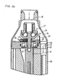
Fig. 2a shows a longitudinal section through the device inFig. 1 and illustrating the normal open position of the device. -
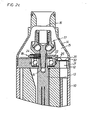
Fig. 2b shows the same section as inFig. 2a but illustrates the device in an activated but not yet closed position. -
Fig. 2c shows the same section as inFig. 2a but illustrates the closed position of the device. -
Fig. 3 shows, on a larger scale, the device inFigs. 1 and2 . - The overspeed safety device illustrated in the drawings is applied on a pneumatic vane motor comprising a
cylinder 10, aforward end wall 11, arear end wall 12, arotor 13 rotatively journalled in theend walls air inlet funnel 14 connected to therear end wall 12. Theinlet funnel 14 forms anair inlet passage 15 and has a supply opening 16 at its rear end. Theopening 16 is controlled by aspeed governor 17 of a conventional ball activated type connected to therotor 13 via aspindle 19. Thespeed governor 17, which is not described in further detail, is intended to keep the motor operating at a predetermined speed level at varying loads by controlling the pressure air supply to the motor via thesupply opening 16. - The overspeeed safety device comprises an
actuator 18 which is supported on thegovernor spindle 19 connected to and co-rotating with therotor 13. The overspeed safety device also includes amovable lid 20 which forms a valve element which is supported on therear end wall 12 of the motor. Thelid 20 is arranged to be shifted by theactuator 18 from an open position to a closed position as the motor speed exceeds the predetermined speed level normally provided by thespeed governor 17. In its closed position thelid 20 is arranged to block the pressure air flow through an inlet opening 21 in therear end wall 12. - The
actuator 18 is supported on thegovernor spindle 19 and comprises acircular disc 22 which is provided with a radially extendingaperture 23 through whoch thespindle 19 extends. In theaperture 23 there is mounted acoil spring 24 for biasing thedisc 22 into a normal concentric position relative to thespindle 19. Since thedisc 22 has a centre of gravity located offset from the geometric centre of thedisc 22 the latter is apt to leave its concentric position at high speed rotation. At a certain speed level the centrifugal action on thedisc 22 will dominate over the bias force of thespring 24 whereby thedisc 22 will move radially. The outer periphery of thedisc 22 forms acam surface 25, and when thedisc 22 leaves its concentric position thecam surface 25 will get into contact with thelid 20 and displace the latter in a radial direction, thereby initiating a closing movement on thelid 20. - The
lid 20 is tiltable about a pivot axis C which forms a chord in relation to the rotation axis of therotor 13. The tilting movement of thelid 20 is retained by a substantiallystraight wire spring 26 the ends of which are received ingrooves rear end wall 12 and secured to therear end wall 12 by twoscrews rear end wall 12 is formed with aflat seat surface 32 surrounding the inlet opening 21, and in its closed position thelid 20 is arranged to cover the inlet opening 21 and engage theseat surface 32. - At its ends, the
lid 20 is formed with aridge portions lid 20. SeeFig. 3 . In the open position of thelid 20 theridge portions wire spring 26 act in the opening direction of thelid 20, and when moved in its closing direction thelid 20 performs an over-centre movement in which theridge portions lid 20 against the action of thewire spring 26. Having passed the top centre of theridge portions spring 26 acts to move thelid 20 in the closing direction. By this over-centre movement accomplished by theridge portions lid 20 gets a bi-stable action, which means that thelid 20 is safely maintained in its open position during normal motor operation and distinctly moved to its closed position when activated by theactuator 18. When activated thelid 20 is urged into its closed position also by the pressure drop in the air flow through the inlet opening 21, but due to the spring / ridge portion arrangement thelid 20 is maintained in its closed position also after the pressure air supply to the motor has been discontinued and no pressure drop acts on thelid 20. - The overspeed safety valve according to the invention is advantageous in that the
valve lid 20 is movable in the radial direction and that theactuator 18 comprises acam surface 25 for engaging and shifting thelid 20 by a relatively gentle force. This means that thelid 20 is not exposed to any detrimental impact forces at activation of the device and may very well be reset and used again, with a maintained proper function and reliability.
Claims (3)
- Overspeed safety device for a pneumatic rotation motor including a cylinder (10), a pressure air inlet opening (21), and a rotor (13), comprising an actuator(18) co-rotating with the rotor (13) and responsive to centrifugal action, and a valve element (20) arranged to control the air flow through the inlet opening (21), said valve element (20) is arranged to be engaged by the actuator (18) for initiating a shifting movement of the valve element (20) from an open position to closed position as the rotor speed exceeds a predetermined maximum speed level, said valve element (20) is formed by a lid which is tiltable about a pivot axis (C) between the open position and the closed position, and said pivot axis (C) extends substantially along a chord related to the centre of the rotor (13), and the actuator (18) is formed with a cam surface (25) for caming engagement with said lid (20) for accomplishing tilting of said lid (20) about said pivot axis (C), wherein• said inlet opening (21) is surrounded by a flat seat surface (32) for sealing engagement by the lid (20) in the closed position of the latter,• said lid (20) is formed with at least one ridge portion (33,34) for resting on said seat surface (32),• a spring (26) is arranged to retain and bias said lid (20) toward said seat surface (32) such that when shifted between the open position and the closed position the lid (20) is made to perform a bi-stable over-centre movement by the ridge portion or portions.
- Device according to claim 1, wherein the motor comprises a forward end wall (11) and a rear end wall (12), and the pressure air inlet opening (21) as well as said lid (20) are located to the rear end wall (12).
- Device according to claim 2, wherein said spring (26) comprises a substantially straight wire spring which at its ends is secured to the rear end wall (12) and tiltably supports the lid (20).
Applications Claiming Priority (2)
| Application Number | Priority Date | Filing Date | Title |
|---|---|---|---|
| SE0401119A SE527476C2 (en) | 2004-04-30 | 2004-04-30 | Surface protection for a rotary motor |
| PCT/SE2005/000632 WO2005105370A1 (en) | 2004-04-30 | 2005-04-29 | Overspeed safety device for a rotation motor |
Publications (2)
| Publication Number | Publication Date |
|---|---|
| EP1750900A1 EP1750900A1 (en) | 2007-02-14 |
| EP1750900B1 true EP1750900B1 (en) | 2009-12-30 |
Family
ID=32322712
Family Applications (1)
| Application Number | Title | Priority Date | Filing Date |
|---|---|---|---|
| EP05738280A Expired - Lifetime EP1750900B1 (en) | 2004-04-30 | 2005-04-29 | Overspeed safety device for a rotation motor |
Country Status (6)
| Country | Link |
|---|---|
| US (1) | US7677863B2 (en) |
| EP (1) | EP1750900B1 (en) |
| JP (1) | JP4610610B2 (en) |
| DE (1) | DE602005018633D1 (en) |
| SE (1) | SE527476C2 (en) |
| WO (1) | WO2005105370A1 (en) |
Families Citing this family (1)
| Publication number | Priority date | Publication date | Assignee | Title |
|---|---|---|---|---|
| US10434327B2 (en) * | 2007-10-31 | 2019-10-08 | The Board Of Trustees Of The Leland Stanford Junior University | Implantable optical stimulators |
Family Cites Families (7)
| Publication number | Priority date | Publication date | Assignee | Title |
|---|---|---|---|---|
| US3767332A (en) * | 1971-08-16 | 1973-10-23 | Black & Decker Mfg Co | Speed control and cut-off device |
| US3923429A (en) * | 1974-06-03 | 1975-12-02 | Chicago Pneumatic Tool Co | Overspeed safety device for rotary tools |
| DE2821074A1 (en) | 1978-05-13 | 1979-11-22 | Bosch Gmbh Robert | COMPRESSED AIR TOOL WITH ROTATING MOTOR |
| JPS6022161B2 (en) * | 1981-02-04 | 1985-05-31 | 瓜生製作株式会社 | Air tool safety device |
| SE9201989L (en) | 1992-06-29 | 1993-08-02 | Atlas Copco Tools Ab | OVERVIEW PROTECTION FOR A PNEUMATIC ROTATION ENGINE |
| SE512868C2 (en) * | 1998-03-27 | 2000-05-29 | Atlas Copco Tools Ab | Speed control unit for a pneumatic rotary motor |
| SE524579C2 (en) * | 2002-10-31 | 2004-08-31 | Atlas Copco Tools Ab | Acquisition protection device for pneumatic rotary motor including a speed dependent actuator |
-
2004
- 2004-04-30 SE SE0401119A patent/SE527476C2/en unknown
-
2005
- 2005-04-29 WO PCT/SE2005/000632 patent/WO2005105370A1/en not_active Ceased
- 2005-04-29 DE DE602005018633T patent/DE602005018633D1/en not_active Expired - Lifetime
- 2005-04-29 EP EP05738280A patent/EP1750900B1/en not_active Expired - Lifetime
- 2005-04-29 US US11/579,218 patent/US7677863B2/en not_active Expired - Fee Related
- 2005-04-29 JP JP2007510661A patent/JP4610610B2/en not_active Expired - Lifetime
Also Published As
| Publication number | Publication date |
|---|---|
| WO2005105370A1 (en) | 2005-11-10 |
| DE602005018633D1 (en) | 2010-02-11 |
| SE0401119L (en) | 2005-10-31 |
| JP2007535638A (en) | 2007-12-06 |
| SE527476C2 (en) | 2006-03-21 |
| US7677863B2 (en) | 2010-03-16 |
| EP1750900A1 (en) | 2007-02-14 |
| US20080025836A1 (en) | 2008-01-31 |
| SE0401119D0 (en) | 2004-04-30 |
| JP4610610B2 (en) | 2011-01-12 |
Similar Documents
| Publication | Publication Date | Title |
|---|---|---|
| US7677863B2 (en) | Overspeed safety device for a rotation motor | |
| US3767332A (en) | Speed control and cut-off device | |
| JPH0474148B2 (en) | ||
| JP3363206B2 (en) | Governor for pneumatic tools | |
| JP4276729B2 (en) | Speed control unit for pneumatic rotary motor | |
| US4346765A (en) | Speed responsive motor shutoff mechanism for fluid operated tool | |
| US4729436A (en) | Ball and disc over-speed shut-off mechanism for a rotary pneumatic tool | |
| EP0010080B1 (en) | Overspeed safety device | |
| US6899514B2 (en) | Overspeed safety device | |
| US4444272A (en) | Overspeed safety device | |
| JP3382668B2 (en) | Safety device in case of overspeed | |
| JP3127374B2 (en) | Air tools with safety devices | |
| US4184819A (en) | Secondary speed sensor for governed air grinders | |
| US4265604A (en) | Rotary pneumatic tool with valve-closing pin actuated upon overspeed | |
| SE528874C2 (en) | Operating device | |
| US3100622A (en) | Turbine governor | |
| JP6260690B2 (en) | Pneumatic power tool with overspeed safety device | |
| JPS6022161B2 (en) | Air tool safety device | |
| US4443164A (en) | Secondary speed sensor for governed air grinders | |
| USRE28573E (en) | Speed control and cut-off device | |
| JPH0420707A (en) | Safety device for gas equipment | |
| JP2008080425A (en) | Device for limiting rotation frequency of air motor | |
| JPS6327153B2 (en) |
Legal Events
| Date | Code | Title | Description |
|---|---|---|---|
| PUAI | Public reference made under article 153(3) epc to a published international application that has entered the european phase |
Free format text: ORIGINAL CODE: 0009012 |
|
| 17P | Request for examination filed |
Effective date: 20061123 |
|
| AK | Designated contracting states |
Kind code of ref document: A1 Designated state(s): DE FR GB IT |
|
| DAX | Request for extension of the european patent (deleted) | ||
| RBV | Designated contracting states (corrected) |
Designated state(s): DE FR GB IT |
|
| GRAP | Despatch of communication of intention to grant a patent |
Free format text: ORIGINAL CODE: EPIDOSNIGR1 |
|
| GRAS | Grant fee paid |
Free format text: ORIGINAL CODE: EPIDOSNIGR3 |
|
| GRAA | (expected) grant |
Free format text: ORIGINAL CODE: 0009210 |
|
| AK | Designated contracting states |
Kind code of ref document: B1 Designated state(s): DE FR GB IT |
|
| REG | Reference to a national code |
Ref country code: GB Ref legal event code: FG4D |
|
| REF | Corresponds to: |
Ref document number: 602005018633 Country of ref document: DE Date of ref document: 20100211 Kind code of ref document: P |
|
| PLBE | No opposition filed within time limit |
Free format text: ORIGINAL CODE: 0009261 |
|
| STAA | Information on the status of an ep patent application or granted ep patent |
Free format text: STATUS: NO OPPOSITION FILED WITHIN TIME LIMIT |
|
| 26N | No opposition filed |
Effective date: 20101001 |
|
| REG | Reference to a national code |
Ref country code: FR Ref legal event code: PLFP Year of fee payment: 12 |
|
| REG | Reference to a national code |
Ref country code: FR Ref legal event code: PLFP Year of fee payment: 13 |
|
| REG | Reference to a national code |
Ref country code: FR Ref legal event code: PLFP Year of fee payment: 14 |
|
| P01 | Opt-out of the competence of the unified patent court (upc) registered |
Effective date: 20230524 |
|
| PGFP | Annual fee paid to national office [announced via postgrant information from national office to epo] |
Ref country code: GB Payment date: 20240429 Year of fee payment: 20 |
|
| PGFP | Annual fee paid to national office [announced via postgrant information from national office to epo] |
Ref country code: DE Payment date: 20240429 Year of fee payment: 20 |
|
| PGFP | Annual fee paid to national office [announced via postgrant information from national office to epo] |
Ref country code: IT Payment date: 20240422 Year of fee payment: 20 Ref country code: FR Payment date: 20240425 Year of fee payment: 20 |
|
| REG | Reference to a national code |
Ref country code: DE Ref legal event code: R071 Ref document number: 602005018633 Country of ref document: DE |
|
| REG | Reference to a national code |
Ref country code: GB Ref legal event code: PE20 Expiry date: 20250428 |
|
| PG25 | Lapsed in a contracting state [announced via postgrant information from national office to epo] |
Ref country code: GB Free format text: LAPSE BECAUSE OF EXPIRATION OF PROTECTION Effective date: 20250428 |