EP1750479A2 - Speaker apparatus, method of manufacturing the same, and frame for the same - Google Patents
Speaker apparatus, method of manufacturing the same, and frame for the same Download PDFInfo
- Publication number
- EP1750479A2 EP1750479A2 EP06118381A EP06118381A EP1750479A2 EP 1750479 A2 EP1750479 A2 EP 1750479A2 EP 06118381 A EP06118381 A EP 06118381A EP 06118381 A EP06118381 A EP 06118381A EP 1750479 A2 EP1750479 A2 EP 1750479A2
- Authority
- EP
- European Patent Office
- Prior art keywords
- frame
- capacitor
- front surface
- terminal lug
- lead wire
- Prior art date
- Legal status (The legal status is an assumption and is not a legal conclusion. Google has not performed a legal analysis and makes no representation as to the accuracy of the status listed.)
- Withdrawn
Links
Images

Classifications
-
- H—ELECTRICITY
- H04—ELECTRIC COMMUNICATION TECHNIQUE
- H04R—LOUDSPEAKERS, MICROPHONES, GRAMOPHONE PICK-UPS OR LIKE ACOUSTIC ELECTROMECHANICAL TRANSDUCERS; ELECTRIC HEARING AIDS; PUBLIC ADDRESS SYSTEMS
- H04R31/00—Apparatus or processes specially adapted for the manufacture of transducers or diaphragms therefor
-
- H—ELECTRICITY
- H04—ELECTRIC COMMUNICATION TECHNIQUE
- H04R—LOUDSPEAKERS, MICROPHONES, GRAMOPHONE PICK-UPS OR LIKE ACOUSTIC ELECTROMECHANICAL TRANSDUCERS; ELECTRIC HEARING AIDS; PUBLIC ADDRESS SYSTEMS
- H04R9/00—Transducers of moving-coil, moving-strip, or moving-wire type
- H04R9/06—Loudspeakers
-
- H—ELECTRICITY
- H04—ELECTRIC COMMUNICATION TECHNIQUE
- H04R—LOUDSPEAKERS, MICROPHONES, GRAMOPHONE PICK-UPS OR LIKE ACOUSTIC ELECTROMECHANICAL TRANSDUCERS; ELECTRIC HEARING AIDS; PUBLIC ADDRESS SYSTEMS
- H04R2499/00—Aspects covered by H04R or H04S not otherwise provided for in their subgroups
- H04R2499/10—General applications
- H04R2499/13—Acoustic transducers and sound field adaptation in vehicles
Definitions
- the present invention relates to a speaker apparatus, a method of manufacturing the speaker apparatus and a frame for the speaker apparatus.
- a capacitor In a small-sized speaker apparatus to be used in an acoustic apparatus for a car, it is a structure in which a capacitor is attached to a frame formed by a resin which constitutes an outer shell of the speaker apparatus, and a capacitor lead wire is connected to a terminal lug of the frame by soldering.
- the capacitor of this type cannot be attached to a front surface side of the frame in respect of a space, and is disposed on a back face or a side portion of the frame.
- JP-A-6-245294 has disclosed an example in which the capacitor is provided in a back part of the frame for the speaker apparatus.
- a U-shaped housing portion is provided on an external wall of a connector terminal portion at the back part of the frame and a protruding dividing plate is provided in a bottom part thereof, a capacitor for reducing a noise is inserted and fixed into the U-shaped housing portion, one of lead wires of the capacitor is connected to the frame along a groove formed in the bottom part of the housing portion and the other lead wire is connected to a terminal of the connector terminal portion, thereby preventing the capacitor from slipping off due to surrounding vibration.
- An attachment of network components such as a capacitor, is formed integrally with a metal frame or a resin frame of a speaker apparatus, or the attachment is molded integrally with the metal frame.
- the reference “ JP-A-2000-152395” discloses such an attachment structure that the capacitor is fitted into the attachment.
- a connecting structure of a lead wire of a speaker and a terminal lug described in Jp-A-6-70395.
- a lead wire is previously cut into a predetermined length set in a design.
- One end of the lead wire has an engaging portion formed by soldering, and the other end of the lead wire is connected to a vibrating system.
- the lead wire is pulled toward the vibrating system side after the lead wire passes through a notched hole of the terminal lug and a clearance between a protrusion of the terminal lug and the terminal lug. In this state, a portion of the lead wire where the lead wire is passed through the notched hole is soldered on the terminal lug.
- a capacitor In a small-sized speaker apparatus, it is hard to provide a capacitor on a front side of the apparatus in respect of a space.
- the capacitor is to be disposed on a back side of a frame of the apparatus.
- a lead wire of the capacitor is usually connected to a terminal portion provided on the frame at the back side of the frame by soldering.
- a voice coil lead wire pulled out of a voice coil is extended toward a front side of the apparatus and is thus connected to the terminal portion of the frame by soldering. Accordingly, a terminal connection of the capacitor lead wire and that of the voice coil lead wire are subjected to a soldering processing on the back and front sides of the apparatus, respectively. Consequently, a processing at another step is forcibly carried out.
- the capacitor to be attached to the speaker described in JP-A-6-245294 is connected between a voice signal terminal and a frame (ground) and is used for reducing a noise. According to an attachment of the capacitor disclosed in JP-A-6-245294 , the capacitor is attached by additional process without changing a conventional process for producing a speaker, and components for attaching the capacitor is reduced. Therefore, An effective structure is not disclosed in JP-A-6-245294 in order to make a work for fixing the capacitor easy and reliable. Also, the effective structure is not disclosed in JP-A-6-245294 in order to make a connection of a capacitor lead terminal reliable.
- a capacitor is inserted into a cylindrical holding piece having a side portion opened. Therefore, the work for attaching the capacitor is easy to perform. However, the capacitor is held by only an elastic force of the holding piece. For this reason, there is a possibility that the capacitor might slip off due to vibration.
- the present invention has been made in view of the following circumstances.
- a capacitor is not fixed securely, and the capacitor slips off if the easiness of a work for attaching the capacitor is to be maintained.
- a work for connecting a capacitor lead wire to a terminal portion and a work for connecting a voice coil lead wire are carried out on both back and front sides of the apparatus in the case in which the capacitor is provided on the back side of the frame.
- These works lead to an increase of producing processes so that a manufacturing cost is increase.
- it is hard to set a plurality of terminal lugs one by one into a mold when the terminal lugs are to be fixed to the frame by insert molding and a workability of a subsequent processing is poor, resulting in a rise in a processing cost.
- a speaker apparatus comprises a frame; a terminal lug attached to a flange portion provided on a front surface of the frame; and a capacitor accommodated in a capacitor housing recessed portion provided on a back face of the frame.
- a voice coil lead wire and a capacitor lead wire of the capacitor are connected to the terminal lug at the front surface of the frame.
- a method of manufacturing a speaker apparatus comprising; fixing a terminal lug to be exposed to a flange portion provided on a front surface of a frame, causing a capacitor lead wire of a capacitor accommodated in a back portion of the frame to penetrate through the terminal lug and protruding the capacitor lead wire toward a front surface of the frame, and connecting the capacitor lead wire to a voice coil lead wire via the terminal lug at the front surface of the frame.
- a speaker apparatus in which a flange portion is formed in connection to a front surface, a capacitor housing recessed portion is formed in a back portion, a terminal lug is fixed to a front surface of the flange portion, and an insertion hole for a capacitor lead wire is formed in the flange portion to penetrate through the terminal lug.
- a frame 1 for a speaker apparatus serves as an outer shell of the speaker apparatus.
- the frame 1 is formed by a resin molded product, and is formed like a cup-shape in order to accommodate a speaker functional portion including a vibrating plate 2 and a voice coil (not shown) on a center of a front surface of the frame.
- a flange portion 5 is formed on an outer periphery in connection to a front surface of the frame 1.
- a capacitor housing recessed portion 6 is formed on a back side of the flange portion 5 provided on the front surface.
- a pair of capacitor lead wire insertion holes 7 and 8 penetrating from a back face of the flange portion 5 to a front surface thereof are formed close to the capacitor housing recessed portion 6.
- the capacitor housing recessed portion 6 is formed, as a rectangular capacitor housing recessed portion.
- the capacitor housing recessed portion 6 has a width to come in pressure contact with the outer peripheral portion of a cylindrical capacitor 9 and a length to come in contact with both end faces of the capacitor 9 (a longitudinal direction of the capacitor).
- An elastic click member 10 for capacitor fixation which serves to push the accommodated capacitor 9 against a wall surface 6a on a front end side (a lead wire pull-out side), is formed on either end in a direction of the length.
- the capacitor 9 is pressed into the capacitor housing recessed portion 6 so as to be pushed in with a finger tip so that an outer peripheral portion thereof is constrained by a capacitor housing recessed portion wall surface 6b in a transverse direction.
- the outer peripheral portion is pushed against the front end side wall surface 6a of the capacitor housing recessed portion 6 by the elastic pressing force of the click member 10.
- the capacitor 9 is thus positioned and fixed into the capacitor housing recessed portion 6 so that the capacitor 9 in not movable.
- a pair of lead wires 11 and 12 of the capacitor 9 is previously bent to form an L-shape.
- a groove portion 13 guides a straight part on the base portion side of the lead wires 11 and 12.
- the groove portion 13 is formed in the back part of the frame 1, and is adjacent to the wall surface 6a on a front end side of the capacitor housing recessed portion 6.
- a position regulating portion 14 has a T-shaped, and the position regulating portion 14 is formed in a central part of the groove portion 13.
- tip portions of the L-shaped lead wires 11 and 12 are inserted into insertion holes 7 and 8 of the capacitor lead wires from the back side of the flange portion 5 so as to be slightly protruded toward the front side of the flange portion 5.
- the separating wall 15 is formed between the insertion holes 7 and 8 of the capacitor lead wires at the back side of the flange portion 5.
- plate-shaped terminal lugs 16 and 17 are fixed to the front surface of the flange portion 5 of the frame 1 in order to surround the insertion holes 7 and 8 of the capacitor lead wires.
- the terminal lug 16 corresponding to the insertion hole 7 of one of the capacitor lead wires and the terminal lug 17 corresponding to the insertion hole 8 of the other capacitor lead wire are separated from each other.
- the terminal lug 16 surrounding the insertion hole 7 has an external connecting end 16a overhung outward from the flange portion 5.
- a third terminal lug 18 is fixed to the front surface of the flange portion 5.
- the third terminal lug 18 is also provided with an external connecting end 18a overhung outward from the flange portion 5.
- the terminal lugs 16 and 17 are provided with holes 20 and 21 for inserting the capacitor lead wires 11 and 12 in order to match the insertion holes 7 and 8 of the capacitor lead wires, respectively.
- the tips of the capacitor lead wires 11 and 12 are slightly protruded from the holes 20 and 21 of the terminal lug 16 and 17 toward the front side of the flange portion 5 through the insertion holes 7 and 8 of the capacitor lead wires in the flange portion 5.
- the capacitor 9 is pressed into the capacitor housing recessed portion 6 on the back face of the frame 1, and the tips of the lead wires 11 and 12 are protruded toward the front surface of the frame 1 via the insertion holes 7 and 8 of the capacitor lead wires in the flange portion 5 and the holes 20 and 21 of the terminal lugs 16 and 17.
- a pair of voice coil lead wires 22 and 23 are pulled from a voice coil (not shown) toward the front surface of the frame 1, and the pair of voice coil lead wires 22, 23 are extended across upper surfaces of the terminal lug 17 where an external connecting end is not provided and the third terminal lug 18 from which the capacitor lead wire is not protruded, respectively.
- the voice coil lead wires 22 and 23 may be tied with outer end portions of the terminal lugs 17 and 18 corresponding thereto and also may be temporarily fixed, respectively.
- the capacitor lead wires 11 and 12 and the terminal lugs 16 and 17 corresponding thereto are soldered in the hole positions of the the terminal lugs 16 and 17 at the front side of the frame 1.
- the voice coil lead wires 22 and 23 and the terminal lugs 17 and 18 corresponding thereto are soldered at the front side of the frame 1 respectively in the same manner.
- the voice coil lead wire 22 is connected to the capacitor lead wire 12 through the terminal lug 17.
- the capacitor lead wire 11 is conducted to the external connecting end 16a of the terminal lug 16 through the terminal lug 16.
- the voice coil lead wire 23 is conducted to the external connecting end 18a through the third terminal lug 18.
- the capacitor 9 and the capacitor lead wires 11 and 12 are reliably fixed to the frame 1 by simply pressing the capacitor 9 into the capacitor housing recessed portion 6 on the back side of the frame 1. Therefore, it is possible to prevent a soldering defect of the terminal lugs 16 and 17 and the capacitor lead wires 11 and 12. Moreover, the capacitor 9 is disposed on the back side of the frame 1 for some reasons of a space. However, the capacitor lead wires 11 and 12 and the voice coil lead wires 22 and 23 can be soldered to the corresponding terminal lugs 16, 17 and 18 at the front side of the frame 1 together, and the capacitor lead wires 11 and 12 and the voice coil lead wires 22 and 23 can be processed in the same process. Consequently, quality of soldering can be enhanced, and furthermore, a cost can be reduced due to a decrease in soldering steps.
- End portions of a pair of terminal lugs 16 and 17 are protruded outward from a side part of a flange portion 5 of a frame 1, and lead wire inserting groove portions 25 and 26 for the lead wires 11 and 12 of a capacitor 9 are formed on which the terminal lugs 16, 17 are protruded.
- the capacitor 9 is pressed into a capacitor housing recessed portion on a back side of the frame 1 in the same manner of the first embodiment.
- the capacitor lead wires 11 and 12 are extended outward from the flange portion 5 of the frame 1, and L-shaped tip portions of the leas wires are directly inserted into the lead wire inserting groove portions 25 and 26 of the terminal lugs 16 and 17, and are thus subjected to a soldering processing.
- a voice coil lead wire 22 pulled to a front surface of the frame 1 is also soldered to the terminal lug 17 in the same manner.
- the capacitor lead wires 11 and 12 and the voice coil lead wire 22 are soldered at the front side of the frame 1 in the same process. Insertion holes of the capacitor lead wires 11 and 12 are not formed on the frame 1.
- the capacitor lead wires 11 and 12 are directly inserted into the groove portions 25 and 26 of the terminal lugs 16 and 17. Therefore, the work can be carried out still more easily.
- the lead wire inserting groove portions 25 and 26 may have a configuration of through holes as in the first embodiment.
- Capacitor lead wires 11 and 12 are not L-shaped, and the capacitor lead wires 11, 12 are extended straight from an end of a capacitor 9.
- a cylindrical capacitor housing recessed portion 27 is formed perpendicularly to a flange portion 5 at a back side of the flange portion 5 of the frame 1.
- Plate-shaped terminal lugs 16 and 17 are fixed to a front surface of the flange portion 5 and insertion holes 28 and 29 for the capacitor lead wires are formed from the flange portion 5 to the terminal lugs 16 and 17 in the same manner as in the first embodiment.
- the capacitor leadwires 11 and 12 are slightly protruded toward the front side of the terminal lugs 16 and 17 through the insertion holes 28 and 29 for the capacitor lead wires.
- a frame body portion formed by a resin and a terminal lug are formed integrally by insert molding.
- a mold in which a rectangular capacitor housing recessed portion 30 is formed on a part of a flange portion 5 of a frame 1.
- an integral terminal lug 31 is disposed on a front surface of the flange portion 5 of the frame 1 across the capacitor housing recessed portion 30.
- the terminal lug 31 has a configuration of a composite terminal taking such a shape that either end side is forked from a central part and the forked portions are positioned into the capacitor housing recessed portion 30 of the frame 1, and the terminal lug 31 and the frame 1 are integrally subjected to insert molding in this state.
- Fig. 7B shows a state obtained after the Insert molding.
- the terminal lug 31 is cut transversely in a position of the capacitor housing recessed portion 30 in the frame 1. Consequently, a pair of branched terminal lugs 16 and 17 is fixed to one of sides of the front surface of the flange portion 5 in the frame 1 and one terminal lug 18 is fixed to the other side.
- the frame 1 for the speaker apparatus has three terminal lugs 16, 17 and 18 separated from each other.
- the lead wires of the capacitor are inserted in the two terminal lugs 16 and 17 on either side and are fixed by soldering respectively, and furthermore, the voice coil lead wire is soldered to one of the two terminal lugs 16 and 17 (having the external connecting end) and the other voice coil lead wire is soldered to the terminal lug 18 on the opposite side which is divided.
- the soldering processing can be carried out in the same process at the front side of the frame 1. Thus, it is possible to reduce a cost by a decrease in steps.
- terminal lugs are molded as single products and are attached one by one to a frame formed by a resin through insert molding or are manually attached by a postprocessing. According to such a method, a processing cost is increased in the case in which the number of the terminals is increased, and it is hard to set a plurality of the terminal lugs into an insert mold or a workability for the postprocessing is deteriorated in the case in which a size of the terminal lug is reduced.
- the terminal lug is integrated and set into the mold together with the frame formed by a resin. Therefore, stable setting can be obtained.
- the capacitor housing recessed portion 30 of the frame 1 may take a U shape, a V shape or a shape of a through hole and the plate-shaped terminal lug 31 may be provided thereacross.
- the capacitor housing recessed portion 30 is not formed on the frame 1 but only the terminal lug is partially protruded outward from the frame 1 and this portion is cut to form a plurality of terminal lugs after insert molding.
- the cut portion of the terminal lug is exposed toward the frame in the fourth embodiment, furthermore, the cut portion of the terminal lug may be covered with such a thin resin that the cutting is not influenced. Moreover, it is also possible to use an integral terminal lug which considers the easiness of press molding of the terminal lug and the readiness of cutting after a postprocessing depending on a shape of a terminal lug which is required.
- the speaker apparatus has such a structure that there are provided the frame 1 for the speaker apparatus, the terminal lugs 16, 17 and 18 alctaohed to the flange portion 5 disposed on the front surface of the frame 1, and the capacitor 9 accommodated in the capacitor housing recessed portion 6 disposed on the back face of the frame 1 and protruded toward the front surface of the frame 1 in such a manner that the capacitor lead wires 11 and 12 penetrate through the terminal lugs 16 and 17, and the voice coil lead wires 22 and 23 and the capacitor lead wires 11 and 12 are connected to the terminal lugs 16, 17 and 18 on the front surface of the frame 1 for the speaker apparatus.
- the capacitor lead wires 11 and 12 are protruded toward the front surface of the frame 1. Therefore, the voice coil lead wires 22 and 23 can be soldered, and at the same time, the capacitor lead wires 11 and 12 can be soldered to the terminal lugs 16, 17 and 18 fixed to the front surface of the frame at the front side of the frame.
- a speaker apparatus in which a workability can be enhanced and high quality of the soldering processing can be obtained.
- the terminal lugs 16, 17 and 18 are fixed to be exposed to the flange portion 5 provided on the front surface of the frame 1 and the lead wires 11 and 12 of the capacitor 9 provided in the back portion of the frame 1 are protruded toward the front surface of the frame 1 through the terminal lugs 16 and 17, and the capacitor lead wires 11 and 12 and the voice coil lead wires 22 and 23 are connected to the front surface of the frame 1 through the terminal luge 16, 17 and 18.
- the capacitor 9 can be attached very easily, and furthermore, the terminal connection of the capacitor lead wires 11 and 12 and the voice coil lead wires 22 and 23 can be carried out in the same process at the front side of the speaker apparatus, and a reduction in a manufacturing cost can be achieved by a decrease in the manufacturing steps and an improvament in a workability.
- the frame for the speaker apparatus has such a structure that the flange portion 5 is formed in connection to the front surface of the frame, the capacitor housing recessed portion 6 is formed in the back portion, the terminal lugs 16, 17 and 18 are fixed to the front surface of the flange portion 5, and the insertion holes 7 and 8 for the capacitor lead wires 11 and 12 are formed in the flange portion 5 in penetration through the terminal lugs 16 and 17.
- the lead wires 11 and 12 of the capacitor 9 pressed into the capacitor housing recessed portion 6 provided on the back face of the frame are protruded toward the front surface of the frame 1. Therefore, the voice coil lead wires 23 and 23 can be soldered, and at the same time, the capacitor lead wires 11 and 12 can be soldered to the terminal lugs 16, 17 and 18 fixed to the front surface of the frame at the front side of the frame.
- the frame 1 for the speaker apparatus in which a workability can be enhanced and high quality of the soldering processing can be obtained.
Landscapes
- Engineering & Computer Science (AREA)
- Physics & Mathematics (AREA)
- Acoustics & Sound (AREA)
- Signal Processing (AREA)
- Manufacturing & Machinery (AREA)
- Audible-Bandwidth Dynamoelectric Transducers Other Than Pickups (AREA)
- Details Of Audible-Bandwidth Transducers (AREA)
Abstract
Description
- The present invention relates to a speaker apparatus, a method of manufacturing the speaker apparatus and a frame for the speaker apparatus.
- In a small-sized speaker apparatus to be used in an acoustic apparatus for a car, it is a structure in which a capacitor is attached to a frame formed by a resin which constitutes an outer shell of the speaker apparatus, and a capacitor lead wire is connected to a terminal lug of the frame by soldering. In many cases, the capacitor of this type cannot be attached to a front surface side of the frame in respect of a space, and is disposed on a back face or a side portion of the frame.
-
JP-A-6-245294 - An attachment of network components, such as a capacitor, is formed integrally with a metal frame or a resin frame of a speaker apparatus, or the attachment is molded integrally with the metal frame. The reference "
JP-A-2000-152395 - In addition, there has been known a connecting structure of a lead wire of a speaker and a terminal lug described in Jp-A-6-70395. In the connecting structure, a lead wire is previously cut into a predetermined length set in a design. One end of the lead wire has an engaging portion formed by soldering, and the other end of the lead wire is connected to a vibrating system. The lead wire is pulled toward the vibrating system side after the lead wire passes through a notched hole of the terminal lug and a clearance between a protrusion of the terminal lug and the terminal lug. In this state, a portion of the lead wire where the lead wire is passed through the notched hole is soldered on the terminal lug.
- In a small-sized speaker apparatus, it is hard to provide a capacitor on a front side of the apparatus in respect of a space. The capacitor is to be disposed on a back side of a frame of the apparatus. A lead wire of the capacitor is usually connected to a terminal portion provided on the frame at the back side of the frame by soldering.
- Moreover, a voice coil lead wire pulled out of a voice coil is extended toward a front side of the apparatus and is thus connected to the terminal portion of the frame by soldering. Accordingly, a terminal connection of the capacitor lead wire and that of the voice coil lead wire are subjected to a soldering processing on the back and front sides of the apparatus, respectively. Consequently, a processing at another step is forcibly carried out.
- The capacitor to be attached to the speaker described in
JP-A-6-245294 JP-A-6-245294 JP-A-6-245294 JP-A-6-245294 - According to an attachment of the network component diclosed in
JP-A-2000-152395 - The present invention has been made in view of the following circumstances. A capacitor is not fixed securely, and the capacitor slips off if the easiness of a work for attaching the capacitor is to be maintained. Also, a work for connecting a capacitor lead wire to a terminal portion and a work for connecting a voice coil lead wire are carried out on both back and front sides of the apparatus in the case in which the capacitor is provided on the back side of the frame. These works lead to an increase of producing processes so that a manufacturing cost is increase. Also, it is hard to set a plurality of terminal lugs one by one into a mold when the terminal lugs are to be fixed to the frame by insert molding and a workability of a subsequent processing is poor, resulting in a rise in a processing cost.
- According an aspect of the invention, a speaker apparatus comprises a frame; a terminal lug attached to a flange portion provided on a front surface of the frame; and a capacitor accommodated in a capacitor housing recessed portion provided on a back face of the frame. A voice coil lead wire and a capacitor lead wire of the capacitor are connected to the terminal lug at the front surface of the frame.
- According to another aspect of the invention, there is provided a method of manufacturing a speaker apparatus comprising; fixing a terminal lug to be exposed to a flange portion provided on a front surface of a frame, causing a capacitor lead wire of a capacitor accommodated in a back portion of the frame to penetrate through the terminal lug and protruding the capacitor lead wire toward a front surface of the frame, and connecting the capacitor lead wire to a voice coil lead wire via the terminal lug at the front surface of the frame.
- According to still another aspect of the invention, there is provide a speaker apparatus in which a flange portion is formed in connection to a front surface, a capacitor housing recessed portion is formed in a back portion, a terminal lug is fixed to a front surface of the flange portion, and an insertion hole for a capacitor lead wire is formed in the flange portion to penetrate through the terminal lug.
-
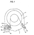
- Fig. 1 is an exemplary plan view showing a speaker apparatus according to a first embodiment of the invention as seen from a front surface thereof;
- Fig. 2 is an exemplary plan view showing the speaker apparatus illustrated in Fig. 1 as seen from a back side thereof;
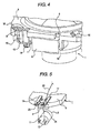
- Fig. 3 is an exemplary partial enlarged perspective view showing a guide portion and a T-shaped position regulating portion in a capacitor lead wire in the speaker apparatus illustrated in Fig. 1;
- Fig. 4 is an exemplary partial enlarged perspective view showing the capacitor lead wire and an insertion hole for the capacitor lead wire of a frame in the speaker apparatus illustrated in Fig. 1;
- Fig. 5 is an exemplary schematic perspective view showing a speaker apparatus according to a second embodiment of the invention;
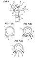
- Fig. 6 is an exemplary schematic perspective view showing a speaker apparatus according to a third embodiment of the invention; and
- Figs. 7A, 7B, and 7C are exemplary views showing a process for manufacturing the frame of the speaker apparatus according to the embodiments.
- With reference to the drawings, embodiments of speaker apparatus and a frame for the speaker apparatus will be described below in detail.
- A frame 1 for a speaker apparatus serves as an outer shell of the speaker apparatus. The frame 1 is formed by a resin molded product, and is formed like a cup-shape in order to accommodate a speaker functional portion including a vibrating plate 2 and a voice coil (not shown) on a center of a front surface of the frame. A
flange portion 5 is formed on an outer periphery in connection to a front surface of the frame 1. - Referring to Fig. 2, a capacitor housing recessed portion 6 is formed on a back side of the
flange portion 5 provided on the front surface. A pair of capacitor leadwire insertion holes 7 and 8 penetrating from a back face of theflange portion 5 to a front surface thereof are formed close to the capacitor housing recessed portion 6. The capacitor housing recessed portion 6 is formed, as a rectangular capacitor housing recessed portion. The capacitor housing recessed portion 6 has a width to come in pressure contact with the outer peripheral portion of a cylindrical capacitor 9 and a length to come in contact with both end faces of the capacitor 9 (a longitudinal direction of the capacitor). Anelastic click member 10 for capacitor fixation, which serves to push the accommodated capacitor 9 against awall surface 6a on a front end side (a lead wire pull-out side), is formed on either end in a direction of the length. - Referring to Figs. 3 and 4, the capacitor 9 is pressed into the capacitor housing recessed portion 6 so as to be pushed in with a finger tip so that an outer peripheral portion thereof is constrained by a capacitor housing recessed
portion wall surface 6b in a transverse direction. The outer peripheral portion is pushed against the front endside wall surface 6a of the capacitor housing recessed portion 6 by the elastic pressing force of theclick member 10. The capacitor 9 is thus positioned and fixed into the capacitor housing recessed portion 6 so that the capacitor 9 in not movable. - According to the first embodiment, a pair of
lead wires groove portion 13 guides a straight part on the base portion side of thelead wires groove portion 13 is formed in the back part of the frame 1, and is adjacent to thewall surface 6a on a front end side of the capacitor housing recessed portion 6. Aposition regulating portion 14 has a T-shaped, and theposition regulating portion 14 is formed in a central part of thegroove portion 13. By theposition regulating portion 14 and a separatingwall 15, the positions of thelead wires - When the capacitor 9 is accommodated in the capacitor housing recessed portion 6, tip portions of the L-shaped
lead wires insertion holes 7 and 8 of the capacitor lead wires from the back side of theflange portion 5 so as to be slightly protruded toward the front side of theflange portion 5. - As shown in Fig. 2, the separating
wall 15 is formed between the insertion holes 7 and 8 of the capacitor lead wires at the back side of theflange portion 5. By theposition regulating portion 14 and the separatingwall 15, a short circuit can be prevented from being caused by an unexpected contact of thelead wires - As shown in Fig. 1, plate-shaped terminal lugs 16 and 17 are fixed to the front surface of the
flange portion 5 of the frame 1 in order to surround the insertion holes 7 and 8 of the capacitor lead wires. Theterminal lug 16 corresponding to the insertion hole 7 of one of the capacitor lead wires and theterminal lug 17 corresponding to theinsertion hole 8 of the other capacitor lead wire are separated from each other. Theterminal lug 16 surrounding the insertion hole 7 has an externalconnecting end 16a overhung outward from theflange portion 5. Separately from the twoterminal luge terminal lug 18 is fixed to the front surface of theflange portion 5. The thirdterminal lug 18 is also provided with an externalconnecting end 18a overhung outward from theflange portion 5. - The terminal lugs 16 and 17 are provided with holes 20 and 21 for inserting the
capacitor lead wires capacitor lead wires terminal lug flange portion 5 through the insertion holes 7 and 8 of the capacitor lead wires in theflange portion 5. - The capacitor 9 is pressed into the capacitor housing recessed portion 6 on the back face of the frame 1, and the tips of the
lead wires flange portion 5 and the holes 20 and 21 of the terminal lugs 16 and 17. A pair of voicecoil lead wires coil lead wires terminal lug 17 where an external connecting end is not provided and the thirdterminal lug 18 from which the capacitor lead wire is not protruded, respectively. The voicecoil lead wires - The
capacitor lead wires coil lead wires coil lead wire 22 is connected to thecapacitor lead wire 12 through theterminal lug 17. Thecapacitor lead wire 11 is conducted to the external connectingend 16a of theterminal lug 16 through theterminal lug 16. The voicecoil lead wire 23 is conducted to the external connectingend 18a through the thirdterminal lug 18. - The capacitor 9 and the
capacitor lead wires capacitor lead wires capacitor lead wires coil lead wires capacitor lead wires coil lead wires - End portions of a pair of terminal lugs 16 and 17 are protruded outward from a side part of a
flange portion 5 of a frame 1, and lead wire insertinggroove portions lead wires capacitor lead wires flange portion 5 of the frame 1, and L-shaped tip portions of the leas wires are directly inserted into the lead wire insertinggroove portions coil lead wire 22 pulled to a front surface of the frame 1 is also soldered to theterminal lug 17 in the same manner. - The
capacitor lead wires coil lead wire 22 are soldered at the front side of the frame 1 in the same process. Insertion holes of thecapacitor lead wires capacitor lead wires groove portions groove portions -
Capacitor lead wires capacitor lead wires portion 27 is formed perpendicularly to aflange portion 5 at a back side of theflange portion 5 of the frame 1. Plate-shaped terminal lugs 16 and 17 are fixed to a front surface of theflange portion 5 and insertion holes 28 and 29 for the capacitor lead wires are formed from theflange portion 5 to the terminal lugs 16 and 17 in the same manner as in the first embodiment. In a state in which the capacitor 9 is pressed into the cylindrical capacitor housing recessedportion 27 from the back side of theflange portion 5, the capacitor leadwires 11 and 12 are slightly protruded toward the front side of the terminal lugs 16 and 17 through the insertion holes 28 and 29 for the capacitor lead wires. In the same manner as in the first and second embodiments, accordingly, it is possible to carry out a soldering processing for thecapacitor lead wires coll lead wire 22 and theterminal lug 17 on the front side of the frame 1 at the same time. Consequently, an L-shape processing for thelead wires - In the frame for the speaker apparatus, a frame body portion formed by a resin and a terminal lug are formed integrally by insert molding. First of all, as shown in Fig. 7A, there is used a mold in which a rectangular capacitor housing recessed
portion 30 is formed on a part of aflange portion 5 of a frame 1. As shown in Fig. 7B, anintegral terminal lug 31 is disposed on a front surface of theflange portion 5 of the frame 1 across the capacitor housing recessedportion 30. In the embodiment, theterminal lug 31 has a configuration of a composite terminal taking such a shape that either end side is forked from a central part and the forked portions are positioned into the capacitor housing recessedportion 30 of the frame 1, and theterminal lug 31 and the frame 1 are integrally subjected to insert molding in this state. Fig. 7B shows a state obtained after the Insert molding. - As shown in Fig. 7C, the
terminal lug 31 is cut transversely in a position of the capacitor housing recessedportion 30 in the frame 1. Consequently, a pair of branchedterminal lugs flange portion 5 in the frame 1 and oneterminal lug 18 is fixed to the other side. The frame 1 for the speaker apparatus has threeterminal lugs - As described in the above embodiments, the lead wires of the capacitor are inserted in the two
terminal lugs terminal lugs 16 and 17 (having the external connecting end) and the other voice coil lead wire is soldered to theterminal lug 18 on the opposite side which is divided. In any case, the soldering processing can be carried out in the same process at the front side of the frame 1. Thus, it is possible to reduce a cost by a decrease in steps. - Referring to the attachment of the terminal to the frame for the speaker apparatus of this type, conventionally, terminal lugs are molded as single products and are attached one by one to a frame formed by a resin through insert molding or are manually attached by a postprocessing. According to such a method, a processing cost is increased in the case in which the number of the terminals is increased, and it is hard to set a plurality of the terminal lugs into an insert mold or a workability for the postprocessing is deteriorated in the case in which a size of the terminal lug is reduced. In the invention, however, the terminal lug is integrated and set into the mold together with the frame formed by a resin. Therefore, stable setting can be obtained.
- While there has been employed the configuration in which the rectangular capacitor housing recessed
portion 30 is formed in theflange portion 5 of the frame 1 and the integral plate-shapedterminal lug 31 is provided across the capacitor housing recessedportion 30 in the seventh embodiment, the capacitor housing recessedportion 30 of the frame 1 may take a U shape, a V shape or a shape of a through hole and the plate-shapedterminal lug 31 may be provided thereacross. Moreover, it is also possible to employ a configuration in which the capacitor housing recessedportion 30 is not formed on the frame 1 but only the terminal lug is partially protruded outward from the frame 1 and this portion is cut to form a plurality of terminal lugs after insert molding. - While the cut portion of the terminal lug is exposed toward the frame in the fourth embodiment, furthermore, the cut portion of the terminal lug may be covered with such a thin resin that the cutting is not influenced. Moreover, it is also possible to use an integral terminal lug which considers the easiness of press molding of the terminal lug and the readiness of cutting after a postprocessing depending on a shape of a terminal lug which is required.
- As described above in detail, the speaker apparatus according to the first embodiment has such a structure that there are provided the frame 1 for the speaker apparatus, the terminal lugs 16, 17 and 18 alctaohed to the
flange portion 5 disposed on the front surface of the frame 1, and the capacitor 9 accommodated in the capacitor housing recessed portion 6 disposed on the back face of the frame 1 and protruded toward the front surface of the frame 1 in such a manner that thecapacitor lead wires coil lead wires capacitor lead wires - By the structure, it is possible to reliably fix the capacitor 9 for characteristic regulation by simply pressing the capacitor 9 into the capacitor housing recessed portion 6 on the back face of the frame. Moreover, the
capacitor lead wires coil lead wires capacitor lead wires - According to the method of manufacturing the speaker apparatus in accordance with the first to third embodiments, moreover, the terminal lugs 16, 17 and 18 are fixed to be exposed to the
flange portion 5 provided on the front surface of the frame 1 and thelead wires capacitor lead wires coil lead wires terminal luge - By the structure, the capacitor 9 can be attached very easily, and furthermore, the terminal connection of the
capacitor lead wires coil lead wires - Moreover, the frame for the speaker apparatus according to the embodiment has such a structure that the
flange portion 5 is formed in connection to the front surface of the frame, the capacitor housing recessed portion 6 is formed in the back portion, the terminal lugs 16, 17 and 18 are fixed to the front surface of theflange portion 5, and the insertion holes 7 and 8 for thecapacitor lead wires flange portion 5 in penetration through the terminal lugs 16 and 17. - By the structure, the
lead wires coil lead wires capacitor lead wires
Claims (5)
- A speaker apparatus comprising:a frame having a flange portion on a front surface thereof and a recessed portion on a back face thereof;a terminal lug attached to the flange portion of the frame;a capacitor accommodated in the recessed portion of the frame, the capacitor having a capacitor lead wire connected to the terminal lug at the front surface of the frame, anda voice coil connected to the terminal lug at the front surface of the frame.
- A method of manufacturing a speaker apparatus comprising:fixing a terminal lug to be exposed to a flange portion provided on a front surface of a frame;causing a capacitor lead wire of a capacitor accommodated in a back portion of the frame to penetrate through the terminal lug and protruding the capacitor lead wire toward a front surface of the frame; andconnecting the capacitor lead wire to a voice coil lead wire via the terminal lug at the front surface of the frame.
- The method of manufacturing a speaker apparatus according to claim 2, comprising:integrating the terminal lug so as to form a plate-shape;insert-molding the integrated terminal luq into the flange portion; anddividing a part of the terminal lug into a plurality of pieces.
- A frame for a speaker apparatus comprising:a flange portion connected to a front surface of the frame;a capacitor housing recessed portion formed in a back portion;a terminal lug fixed to a front surface of the flange portion; andan insertion hole for a capacitor lead wire formed in the flange portion to penetrate via the terminal lug.
- The frame for a speaker apparatus according to claim 4, wherein a position regulating guide portion for the capacitor lead wire is adj acent to the capacitor housing recessed portion.
Applications Claiming Priority (1)
| Application Number | Priority Date | Filing Date | Title |
|---|---|---|---|
| JP2005225463A JP4482500B2 (en) | 2005-08-03 | 2005-08-03 | Speaker device, method for manufacturing speaker device, and frame for speaker device |
Publications (2)
| Publication Number | Publication Date |
|---|---|
| EP1750479A2 true EP1750479A2 (en) | 2007-02-07 |
| EP1750479A3 EP1750479A3 (en) | 2009-09-02 |
Family
ID=37314589
Family Applications (1)
| Application Number | Title | Priority Date | Filing Date |
|---|---|---|---|
| EP06118381A Withdrawn EP1750479A3 (en) | 2005-08-03 | 2006-08-03 | Speaker apparatus, method of manufacturing the same, and frame for the same |
Country Status (4)
| Country | Link |
|---|---|
| US (1) | US20070030994A1 (en) |
| EP (1) | EP1750479A3 (en) |
| JP (1) | JP4482500B2 (en) |
| CN (1) | CN1942021A (en) |
Families Citing this family (24)
| Publication number | Priority date | Publication date | Assignee | Title |
|---|---|---|---|---|
| US10158337B2 (en) | 2004-08-10 | 2018-12-18 | Bongiovi Acoustics Llc | System and method for digital signal processing |
| US10848118B2 (en) | 2004-08-10 | 2020-11-24 | Bongiovi Acoustics Llc | System and method for digital signal processing |
| US11431312B2 (en) | 2004-08-10 | 2022-08-30 | Bongiovi Acoustics Llc | System and method for digital signal processing |
| US8284955B2 (en) | 2006-02-07 | 2012-10-09 | Bongiovi Acoustics Llc | System and method for digital signal processing |
| US10069471B2 (en) | 2006-02-07 | 2018-09-04 | Bongiovi Acoustics Llc | System and method for digital signal processing |
| US10848867B2 (en) | 2006-02-07 | 2020-11-24 | Bongiovi Acoustics Llc | System and method for digital signal processing |
| US10701505B2 (en) | 2006-02-07 | 2020-06-30 | Bongiovi Acoustics Llc. | System, method, and apparatus for generating and digitally processing a head related audio transfer function |
| US11202161B2 (en) | 2006-02-07 | 2021-12-14 | Bongiovi Acoustics Llc | System, method, and apparatus for generating and digitally processing a head related audio transfer function |
| JP5182690B2 (en) * | 2008-02-15 | 2013-04-17 | トヨタ自動車株式会社 | Speaker unit mounting structure and speaker mounting bracket |
| CN103905966A (en) * | 2012-12-28 | 2014-07-02 | 美律电子(深圳)有限公司 | Vibration diaphragm molding and voice coil pasting process |
| US9883318B2 (en) | 2013-06-12 | 2018-01-30 | Bongiovi Acoustics Llc | System and method for stereo field enhancement in two-channel audio systems |
| US9264004B2 (en) | 2013-06-12 | 2016-02-16 | Bongiovi Acoustics Llc | System and method for narrow bandwidth digital signal processing |
| US9906858B2 (en) | 2013-10-22 | 2018-02-27 | Bongiovi Acoustics Llc | System and method for digital signal processing |
| US10639000B2 (en) | 2014-04-16 | 2020-05-05 | Bongiovi Acoustics Llc | Device for wide-band auscultation |
| US10820883B2 (en) | 2014-04-16 | 2020-11-03 | Bongiovi Acoustics Llc | Noise reduction assembly for auscultation of a body |
| CN107949878B (en) * | 2015-09-01 | 2021-12-21 | 株式会社电装电子 | Sound generator |
| JP6572846B2 (en) * | 2015-09-01 | 2019-09-11 | アンデン株式会社 | Sound generator |
| US9906867B2 (en) | 2015-11-16 | 2018-02-27 | Bongiovi Acoustics Llc | Surface acoustic transducer |
| US9621994B1 (en) | 2015-11-16 | 2017-04-11 | Bongiovi Acoustics Llc | Surface acoustic transducer |
| CN107182016B (en) * | 2017-06-29 | 2022-05-03 | 潍坊歌尔丹拿电子科技有限公司 | Loudspeaker |
| US11211043B2 (en) | 2018-04-11 | 2021-12-28 | Bongiovi Acoustics Llc | Audio enhanced hearing protection system |
| WO2020028833A1 (en) | 2018-08-02 | 2020-02-06 | Bongiovi Acoustics Llc | System, method, and apparatus for generating and digitally processing a head related audio transfer function |
| CN108810767B (en) * | 2018-08-03 | 2020-11-17 | 瑞声科技(新加坡)有限公司 | Loudspeaker and manufacturing method thereof |
| CN211019223U (en) * | 2020-01-15 | 2020-07-14 | 声电电子科技(惠州)有限公司 | External magnetic structure voice coil lead wire symmetrical suspension type micro loudspeaker |
Citations (2)
| Publication number | Priority date | Publication date | Assignee | Title |
|---|---|---|---|---|
| JPH06245294A (en) | 1993-02-17 | 1994-09-02 | Matsushita Electric Ind Co Ltd | Speaker |
| JP2000152395A (en) | 1998-11-17 | 2000-05-30 | Kenwood Corp | Attachment structure for network component |
Family Cites Families (4)
| Publication number | Priority date | Publication date | Assignee | Title |
|---|---|---|---|---|
| US4979220A (en) * | 1988-05-05 | 1990-12-18 | Audiovox International Limited | Integral body speaker with detachable terminal plate |
| JPH08140186A (en) * | 1994-11-08 | 1996-05-31 | Matsushita Electric Ind Co Ltd | Speaker |
| US5757945A (en) * | 1995-04-12 | 1998-05-26 | Kabushiki Kaisha Kenwood | Terminal for speaker |
| GB9712964D0 (en) * | 1997-06-19 | 1997-08-27 | Goodmans Loudspeakers Limited | Loudspeakers |
-
2005
- 2005-08-03 JP JP2005225463A patent/JP4482500B2/en not_active Expired - Lifetime
-
2006
- 2006-08-02 US US11/497,522 patent/US20070030994A1/en not_active Abandoned
- 2006-08-03 CN CNA2006101042242A patent/CN1942021A/en active Pending
- 2006-08-03 EP EP06118381A patent/EP1750479A3/en not_active Withdrawn
Patent Citations (2)
| Publication number | Priority date | Publication date | Assignee | Title |
|---|---|---|---|---|
| JPH06245294A (en) | 1993-02-17 | 1994-09-02 | Matsushita Electric Ind Co Ltd | Speaker |
| JP2000152395A (en) | 1998-11-17 | 2000-05-30 | Kenwood Corp | Attachment structure for network component |
Also Published As
| Publication number | Publication date |
|---|---|
| CN1942021A (en) | 2007-04-04 |
| JP2007043484A (en) | 2007-02-15 |
| US20070030994A1 (en) | 2007-02-08 |
| JP4482500B2 (en) | 2010-06-16 |
| EP1750479A3 (en) | 2009-09-02 |
Similar Documents
| Publication | Publication Date | Title |
|---|---|---|
| US20070030994A1 (en) | Speaker apparatus, method of manufacturing the same, and frame for the same | |
| KR101044580B1 (en) | connector | |
| EP2433338B1 (en) | Water seal plug and connector with the water seal plug | |
| US7192301B2 (en) | Electrical connector | |
| CN101673891A (en) | A joint connector, joint terminal, a wiring harness with a joint connector and method of assembling it | |
| KR20130039662A (en) | Coaxial connector apparatus | |
| KR100702399B1 (en) | Flexible printed wiring board crimp terminal and core crimping structure using it | |
| EP3343702A1 (en) | Terminal block | |
| KR20080084638A (en) | Multipole Coaxial Connector | |
| JP2015056209A (en) | Electrical connector terminal and electrical connector | |
| US11909151B2 (en) | Electrical connector which can prevent deformation of core wire of coaxial cable caused by applied pressure onto the coaxial cable at time of crimping outer contact onto the coaxial cable | |
| JP4036370B2 (en) | Electrical connector and manufacturing method thereof | |
| EP2827459A1 (en) | Connector | |
| KR20060050385A (en) | Connector and Cable Retainer | |
| JP4474235B2 (en) | connector | |
| EP3902066A1 (en) | Terminal block | |
| JP6193050B2 (en) | Pressure welding connector, pressure welding connector with wire, and connection method between pressure welding connector and covered wire | |
| JP2001110466A (en) | ID connector | |
| JP2003007408A (en) | Electrical connector | |
| KR101918298B1 (en) | Portable terminal | |
| US9825376B2 (en) | Pressure welding contact having a bellows type terminal and pressure welding connector | |
| JP4102295B2 (en) | Piercing terminal for coaxial cable | |
| CN110768051B (en) | Connector | |
| WO2010029392A1 (en) | Retaining element for a connector | |
| CN212062743U (en) | Connector terminal |
Legal Events
| Date | Code | Title | Description |
|---|---|---|---|
| PUAI | Public reference made under article 153(3) epc to a published international application that has entered the european phase |
Free format text: ORIGINAL CODE: 0009012 |
|
| AK | Designated contracting states |
Kind code of ref document: A2 Designated state(s): AT BE BG CH CY CZ DE DK EE ES FI FR GB GR HU IE IS IT LI LT LU LV MC NL PL PT RO SE SI SK TR |
|
| AX | Request for extension of the european patent |
Extension state: AL BA HR MK YU |
|
| PUAL | Search report despatched |
Free format text: ORIGINAL CODE: 0009013 |
|
| AK | Designated contracting states |
Kind code of ref document: A3 Designated state(s): AT BE BG CH CY CZ DE DK EE ES FI FR GB GR HU IE IS IT LI LT LU LV MC NL PL PT RO SE SI SK TR |
|
| AX | Request for extension of the european patent |
Extension state: AL BA HR MK RS |
|
| AKX | Designation fees paid | ||
| STAA | Information on the status of an ep patent application or granted ep patent |
Free format text: STATUS: THE APPLICATION IS DEEMED TO BE WITHDRAWN |
|
| 18D | Application deemed to be withdrawn |
Effective date: 20100303 |
|
| REG | Reference to a national code |
Ref country code: DE Ref legal event code: 8566 |