EP1750125A1 - Column for liquid chromatography and method of packing a chromatography column - Google Patents
Column for liquid chromatography and method of packing a chromatography column Download PDFInfo
- Publication number
- EP1750125A1 EP1750125A1 EP06253673A EP06253673A EP1750125A1 EP 1750125 A1 EP1750125 A1 EP 1750125A1 EP 06253673 A EP06253673 A EP 06253673A EP 06253673 A EP06253673 A EP 06253673A EP 1750125 A1 EP1750125 A1 EP 1750125A1
- Authority
- EP
- European Patent Office
- Prior art keywords
- column
- piston
- porous plug
- chamber
- bore
- Prior art date
- Legal status (The legal status is an assumption and is not a legal conclusion. Google has not performed a legal analysis and makes no representation as to the accuracy of the status listed.)
- Granted
Links
Images

Classifications
-
- G—PHYSICS
- G01—MEASURING; TESTING
- G01N—INVESTIGATING OR ANALYSING MATERIALS BY DETERMINING THEIR CHEMICAL OR PHYSICAL PROPERTIES
- G01N30/00—Investigating or analysing materials by separation into components using adsorption, absorption or similar phenomena or using ion-exchange, e.g. chromatography or field flow fractionation
- G01N30/02—Column chromatography
- G01N30/60—Construction of the column
- G01N30/6004—Construction of the column end pieces
- G01N30/6021—Adjustable pistons
-
- G—PHYSICS
- G01—MEASURING; TESTING
- G01N—INVESTIGATING OR ANALYSING MATERIALS BY DETERMINING THEIR CHEMICAL OR PHYSICAL PROPERTIES
- G01N30/00—Investigating or analysing materials by separation into components using adsorption, absorption or similar phenomena or using ion-exchange, e.g. chromatography or field flow fractionation
- G01N30/02—Column chromatography
- G01N30/50—Conditioning of the sorbent material or stationary liquid
- G01N30/56—Packing methods or coating methods
-
- G—PHYSICS
- G01—MEASURING; TESTING
- G01N—INVESTIGATING OR ANALYSING MATERIALS BY DETERMINING THEIR CHEMICAL OR PHYSICAL PROPERTIES
- G01N30/00—Investigating or analysing materials by separation into components using adsorption, absorption or similar phenomena or using ion-exchange, e.g. chromatography or field flow fractionation
- G01N30/02—Column chromatography
- G01N30/04—Preparation or injection of sample to be analysed
- G01N30/06—Preparation
- G01N30/08—Preparation using an enricher
- G01N2030/085—Preparation using an enricher using absorbing precolumn
-
- G—PHYSICS
- G01—MEASURING; TESTING
- G01N—INVESTIGATING OR ANALYSING MATERIALS BY DETERMINING THEIR CHEMICAL OR PHYSICAL PROPERTIES
- G01N30/00—Investigating or analysing materials by separation into components using adsorption, absorption or similar phenomena or using ion-exchange, e.g. chromatography or field flow fractionation
- G01N30/02—Column chromatography
- G01N30/60—Construction of the column
- G01N30/6034—Construction of the column joining multiple columns
- G01N30/6039—Construction of the column joining multiple columns in series
-
- Y—GENERAL TAGGING OF NEW TECHNOLOGICAL DEVELOPMENTS; GENERAL TAGGING OF CROSS-SECTIONAL TECHNOLOGIES SPANNING OVER SEVERAL SECTIONS OF THE IPC; TECHNICAL SUBJECTS COVERED BY FORMER USPC CROSS-REFERENCE ART COLLECTIONS [XRACs] AND DIGESTS
- Y10—TECHNICAL SUBJECTS COVERED BY FORMER USPC
- Y10T—TECHNICAL SUBJECTS COVERED BY FORMER US CLASSIFICATION
- Y10T29/00—Metal working
- Y10T29/49—Method of mechanical manufacture
- Y10T29/496—Multiperforated metal article making
Definitions
- the present invention relates to a column for liquid chromatography, preferably with adjustable compression, and to a method of packing a chromatography column.
- High performance liquid chromatography is a process by which one or more compounds from a chemical mixture may be separated and identified.
- a transport liquid for example a solvent
- a sample of the chemical mixture to be analyzed is injected into the column.
- the different compounds each one having a different affinity for the packing medium, move through the column at different speeds.
- Those compounds having greater affinity for the packing material move more slowly through the column than those having less affinity, and this speed differential results in the compounds being separated from one another as they pass through the column.
- the transport liquid with the separated compounds exits the column and passes through a detector, which identifies the molecules, for example by spectrophotometric absorbance measurements.
- a two dimensional plot of the detector measurements against elution time or volume, known as a chromatogram, may be made, and from the chromatogram the compounds may be identified.
- the chromatogram displays a separate curve or "peak". Effective separation of the compounds by the column is advantageous because it provides for measurements yielding well defined peaks having sharp maxima inflection points and narrow base widths, allowing excellent resolution and reliable identification of the mixture constituents. Broad peaks, caused by poor column performance, are undesirable as they may allow minor components of the mixture to be masked by major components and go unidentified.
- the uniformity of the packing medium within the column has a significant effect on column performance. It is desired that the particles comprising the packing medium be perfectly arranged and completely homogeneous so that the transport liquid and the sample mixture move at uniform rates through the column. Areas of loose packing medium create channels causing locally increased flow rates while areas that are partially plugged due to particle aggregation create eddies that retard the flow. Such local variations in the flow rate caused by non-uniform packing medium result in transport liquid mixing that degrades the column performance resulting in broadening of the peaks and a concomitant decrease the resolving capability of the HPLC apparatus.
- Columns for HPLC are packed with packing media comprising, for example, silane derivatized silica spheres having a diameter less than 20 microns.
- Packing is performed at high pressures, typically between 7,000 and 9,000 psi, three to four times the pressure at which the column will operate. Under such high pressures, the columns, made from thick wall steel tubing, will expand radially as much as five packing particle diameters depending upon the ratio of wall thickness to inner diameter.
- the pressure is removed and the remaining column components are installed. Removal of the pressure allows the column to relax and contract radially to its nominal diameter. This places the packing media under compression, and the hydraulically oriented layers of packing media buckle and shift in response. The buckling action disrupts the uniformity of the layers which adversely affects column performance.
- the present invention seeks to provide an improved chromatography column and an improved method of packing a chromatography column.
- the method is preferably for packing a high performance chromatography column.
- the preferred embodiment can provide an HPLC column which does not suffer disruption of the hydraulic orientation of the packing media upon removal of the pressure imposed during packing.
- the preferred column for liquid chromatography is designed to contain a packing medium and comprises a chamber for receiving the packing medium.
- the chamber is in the form of an elongated tube defining an axial bore.
- a first opening is positioned in the chamber for passing liquid through the chamber.
- a first porous plug for example a frit formed of porous stainless steel, is positioned overlying the first opening for retaining the medium within the chamber.
- a second porous plug also for retaining the medium within the chamber, is movable within the chamber.
- a piston is in facing relation with the second porous plug. The piston is movable within the chamber for compressing the second porous plug against the medium.
- a second opening, positioned in the piston cooperates with the first opening and allows liquid to pass through the chamber.
- a fitting is mounted on the chamber and engages the piston. The fitting is adjustably movable for moving the piston within the chamber.
- the first and second porous plugs interfit within the bore with an interference fit.
- a seal is mounted on the piston and positioned between a surface of the piston and the bore of the tube.
- the seal is preferably an extrusion type seal.
- a thrust bearing is positioned between the fitting and the piston.
- the piston may also comprise a chamber positioned between the piston opening and the second porous plug.
- a third porous plug is positioned within the chamber adjacent to the opening.
- a fourth porous plug is positioned within the chamber in spaced relation away from the third porous plug.
- the chamber is adapted to receive the packing medium between the third and fourth porous plugs. The piston thereby acts as a movable guard column.
- the preferred method of packing a high performance liquid chromatography column with a packing medium comprises the steps of securing a first porous plug within a bore of the column, the first porous plug for retaining the packing medium within the column; filling the bore with the packing medium; positioning a movable porous plug within the bore so as to engage the packing medium; positioning a movable piston within the bore so as to engage the movable porous plug; pressurizing the bore; moving the piston into the bore, thereby moving the movable porous plug and compressing the packing medium; holding the piston in position compressing the packing medium; and depressurizing the bore.
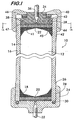
- Figure 1 shows a longitudinal sectional view of an HPLC column 10 according to an embodiment of the invention.
- Column 10 may be any type of column used in liquid chromatography, for example, an analytical column, a preparatory column or a guard column.
- the column 10 comprises a chamber 12, preferably defined by the axial bore 14 of an elongated tube 16.
- a packing medium for example, silane derivatized silica spheres having a diameter less than 20 microns, is received within the bore 14.
- the medium is captured between porous plugs 20 and 22 which are press fit within the bore 14.
- Plugs 20 and 22 are preferably sintered stainless steel frits that allow the transport liquid and the analysis sample to pass while retaining the packing medium in place.
- the plugs 20 and 22 are pressed into bore 14 with an interference fit typically between 0.004 and 0.006 inches depending on the size of the column and the operating pressure. This degree of interference fit allows the plugs to seal against the inner surface of tube 16 and prevent leakage of the packing medium while allowing the plugs to move axially within the bore.
- the press fit of the plugs eliminates the need for additional seals which would increase the cost of the column and decrease its performance by causing dead space that would promote mixing of the transport liquid.
- plug 20 is supported within bore 14 by a fitting 24 that is attached to the tube 16 by complementary threads 26 and 28 on the outer surface of tube 16 and the inner surface of the fitting 24 respectively.
- a seal 30 is positioned between tube 16 and the fitting 24 to prevent leakage of the transport liquid.
- Fitting 24 has an opening 32 that is in fluid communication with the bore 14 through the porous plug 20. Opening 32 allows the transport liquid to pass through the column 10, and may serve as either an inlet or an outlet. In this example, opening 32 in fitting 24 is the column outlet. Opening 32 is adapted to connect to capillary tubing for integration of the column 10 into a high performance liquid chromatograph (not shown).
- Porous plug 22 is engaged with a piston 34 that is movable within axial bore 14.
- Piston 34 has an opening 36 in fluid communication with the bore through plug 22. Opening 36 is also adapted to connect to capillary tubing for integrating the column into a high performance liquid chromatograph.
- opening 36 serves as the inlet to the column, but in some embodiments it could also be an outlet.
- a seal 38 is positioned between the piston 34 and the inner surface of tube 16.
- Seal 38 is preferably formed of perfluoro elastomeric material marketed under the trade names CHEMRAZ and KALREZ.
- Seal 38 is preferably rectangular in cross section and operates as an "extrusion" type seal which seals more tightly without overstressing the seal material by deformation when subjected to increased pressure within bore 14.
- Seal 38 operates effectively when two of its surfaces are in contact with the two parts which are to be sealed (in this example, piston 34 and tube 16), and the space between the parts is sufficiently small so as to prevent extrusion of the seal between them when subjected to pressure.
- Piston 34 is captured within axial bore 14 by a fitting 40.
- Fitting 40 is attached to the tube 16 by threads 42 on the tube that engage complementary threads 44 on the fitting 40.
- a thrust bearing 46 is positioned between the fitting 40 and the piston 34 to reduce the friction between the piston and the fitting as the fitting is turned.
- the thrust bearing is preferably a roller type bearing but may alternately comprise a Teflon washer. Rotation of the fitting 40 forces the piston 34 and the porous plug 22 into axial bore 14 to compress the packing medium 18 as described below.
- a flow distribution disk 41 may be positioned between the piston 34 and the porous plug 22.
- the disk best shown in Figure 1A, has a plurality of radially extending channels 45 and acts as a baffle plate to conduct liquid flowing into column 10 to the circumference 47 of the disk.
- Disk 41 facilitates a more uniform flow of liquid through the column by initially directing the flow away from the centre of the column and thereby counteracting the natural tendency of the fluid to flow faster through the centre of the tube 16 than the flow adjacent to the inner surface of the bore.
- the various components described above are made from materials that are inert to organic solvents comprising the transport liquid as well as to the compounds comprising the analysis sample. Furthermore, the materials must have sufficient strength to withstand the high pressures (12,000 psi and greater) at which the columns are prepared and operated. Stainless steel is a preferred material for the tube 16, the porous plugs 20 and 22, the piston 34 and the fittings 24 and 40 because it has both the properties of inertness and high strength.
- the movable piston 34 and porous plug 22 will provide an improvement in column stability and performance by permitting precise control of the compression of the packing medium 18 within the tube 16 during column preparation and use, as described in the examples provided below.
- porous plug 20 is pressed into bore 14 of tube 16. Fitting 24 with seal 30 is threaded onto the tube to support the plug 20 and engage the seal with the tube in sealing engagement.
- the packing medium 18 is loaded into axial bore 14 and the porous plug 22 is press fit into the bore 14 providing some initial compression to the packing medium.
- Piston 34 (with seal 38) is then inserted into the bore and fitting 40 is threaded onto tube 16 into engagement with the piston 34.
- Column 10 is then connected to a high pressure flushing pump via inlet and outlet openings 36 and 32 and subjected to high internal pressure. This causes the tube to expand radially, and the packing medium 18 is arranged into hydraulically oriented layers supported against porous plug 20.
- fitting 40 While the tube is under pressure from the high pressure flushing pump, fitting 40 is tightened, using a tool if required, to force the piston 34 into the axial bore 14 and force the porous plug 22 against the medium 18. Fitting 40 is tightened sufficiently to capture and hold the packing compression of the medium and the volume expansion of the tube under the high pressure of the flushing pump. By compressing the packing medium when the tube is expanded under pressure using the movable piston and porous plug, the tube is prevented from relaxing and returning to its nominal diameter once the pressure is removed. The hydraulic orientation of the packing medium attained during the high pressure flush is thus preserved, providing a stable, uniform bed of packing medium to maximize column performance.
- Another packing method using the movable piston and porous plug would include the steps of loading the column 10 with packing medium under pressure, removing the pressure and pressing the porous plug 20 into the axial bore 14 to restore the lost packing compression, and then inserting piston 34 into the bore and tightening the fitting 40 to a predetermined torque to maintain the packing medium compression.
- the column is again loaded under pressure, the pressure is removed, and the porous plug is press fit into the axial bore into contact with but not compressing the packing medium.
- the piston is then inserted into the bore and the fitting 40 is tightened to restore the packing medium compression lost when the pressure was removed to install the porous plug and the piston.
- the pitch of threads 42 and 44 can be chosen to provide a convenient rate of advance of piston 34 with rotation of fitting 40. For example, 20 threads per inch would yield a piston advance rate of 0.005 inches per 30 degrees of fitting rotation.
- a fixed circumferential degree scale could be added to the outer surface of tube 16, the scale being used with an index mark positioned on fitting 40 to facilitate precision and reproducibility of the packing medium compression.
- the movable piston and porous plug may also be used to restore packing material compression as the bed of packing material degrades over time.
- the fitting 40 may be tightened to increase the compression of the packing material and thereby eliminate areas of loose packing material detrimental to column performance.
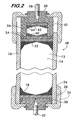
- FIG. 2 shows an embodiment of an HPLC column 48 according to an embodiment of the invention wherein the piston 50 includes a guard column 52.
- Guard columns are positioned upstream of analytical and preparatory columns and are used tc trap impurities or particulates in the analysis sample or the transport liquid that may foul the downstream column and degrade its performance and shorten its useful life.
- piston 50 is movable within axial bore 14 of tube 16 and carries a seal 54 preventing transport fluid leakage.
- Piston 50 engages porous plug 22, which is press fit and movable within the bore 14.
- the piston 50 also has a chamber 56 positioned between its inlet opening 58 and the porous plug 22. Additional porous plugs 60 and 62 are positioned within the chamber 56 in spaced relation to one another defining a space wherein packing medium 64 of the guard column is contained.
- the chamber 56 of the guard column 52 is directly coupled in a through-bore arrangement with axial bore 14 as disclosed in US-A-6,679,989 . Such an arrangement reduces the potential for mixing of the transport liquid as it passes from the guard column into the bore 14 by avoiding an abrupt change in the cross sectional area of the flow path through the column. Mixing of the transport liquid is preferably avoided because it degrades column performance.
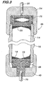
- FIG. 3 Another embodiment of an HPLC column 66 according to an embodiment of the invention is shown in Figure 3.
- Column 66 has a movable piston 68 with an opening 70 that forms the outlet from the column.
- Outlet opening 70 is in fluid communication with the axial bore 14 of tube 16 through the movable porous plug 22 press fit within the bore.
- Fitting 40 is threadedly engaged with tube 16 and rotation of the fitting moves the piston 68 and the porous plug 22 to compress the packing medium 18 similarly to the embodiments described above.
- a guard column 72 is positioned at the opposite end of the tube 16 between the fitting 24 and the porous plug 20. In this embodiment, opening 32 of fitting 24 forms the inlet to the column.
Landscapes
- Physics & Mathematics (AREA)
- Health & Medical Sciences (AREA)
- Life Sciences & Earth Sciences (AREA)
- Chemical & Material Sciences (AREA)
- Analytical Chemistry (AREA)
- Biochemistry (AREA)
- General Health & Medical Sciences (AREA)
- General Physics & Mathematics (AREA)
- Immunology (AREA)
- Pathology (AREA)
- Treatment Of Liquids With Adsorbents In General (AREA)
Abstract
Description
- The present invention relates to a column for liquid chromatography, preferably with adjustable compression, and to a method of packing a chromatography column.
- High performance liquid chromatography (HPLC) is a process by which one or more compounds from a chemical mixture may be separated and identified. A transport liquid, for example a solvent, is pumped under high pressure through a column of packing medium, and a sample of the chemical mixture to be analyzed is injected into the column. As the sample passes through the column with the liquid, the different compounds, each one having a different affinity for the packing medium, move through the column at different speeds. Those compounds having greater affinity for the packing material move more slowly through the column than those having less affinity, and this speed differential results in the compounds being separated from one another as they pass through the column.
- The transport liquid with the separated compounds exits the column and passes through a detector, which identifies the molecules, for example by spectrophotometric absorbance measurements. A two dimensional plot of the detector measurements against elution time or volume, known as a chromatogram, may be made, and from the chromatogram the compounds may be identified.
- For each compound, the chromatogram displays a separate curve or "peak". Effective separation of the compounds by the column is advantageous because it provides for measurements yielding well defined peaks having sharp maxima inflection points and narrow base widths, allowing excellent resolution and reliable identification of the mixture constituents. Broad peaks, caused by poor column performance, are undesirable as they may allow minor components of the mixture to be masked by major components and go unidentified.
- The uniformity of the packing medium within the column has a significant effect on column performance. It is desired that the particles comprising the packing medium be perfectly arranged and completely homogeneous so that the transport liquid and the sample mixture move at uniform rates through the column. Areas of loose packing medium create channels causing locally increased flow rates while areas that are partially plugged due to particle aggregation create eddies that retard the flow. Such local variations in the flow rate caused by non-uniform packing medium result in transport liquid mixing that degrades the column performance resulting in broadening of the peaks and a concomitant decrease the resolving capability of the HPLC apparatus.
- Columns for HPLC are packed with packing media comprising, for example, silane derivatized silica spheres having a diameter less than 20 microns. Packing is performed at high pressures, typically between 7,000 and 9,000 psi, three to four times the pressure at which the column will operate. Under such high pressures, the columns, made from thick wall steel tubing, will expand radially as much as five packing particle diameters depending upon the ratio of wall thickness to inner diameter. Upon completion of packing, the pressure is removed and the remaining column components are installed. Removal of the pressure allows the column to relax and contract radially to its nominal diameter. This places the packing media under compression, and the hydraulically oriented layers of packing media buckle and shift in response. The buckling action disrupts the uniformity of the layers which adversely affects column performance.
- The present invention seeks to provide an improved chromatography column and an improved method of packing a chromatography column.
- According to an aspect of the present invention, there is provided a column for liquid chromatography as specified in claim 1.
- According to another aspect of the present invention, there is provided a method of packing a liquid chromatography column as specified in
claim 10. The method is preferably for packing a high performance chromatography column. - The preferred embodiment can provide an HPLC column which does not suffer disruption of the hydraulic orientation of the packing media upon removal of the pressure imposed during packing.
- The preferred column for liquid chromatography is designed to contain a packing medium and comprises a chamber for receiving the packing medium. Preferably, the chamber is in the form of an elongated tube defining an axial bore. A first opening is positioned in the chamber for passing liquid through the chamber. A first porous plug, for example a frit formed of porous stainless steel, is positioned overlying the first opening for retaining the medium within the chamber. A second porous plug, also for retaining the medium within the chamber, is movable within the chamber. A piston is in facing relation with the second porous plug. The piston is movable within the chamber for compressing the second porous plug against the medium. A second opening, positioned in the piston, cooperates with the first opening and allows liquid to pass through the chamber. A fitting is mounted on the chamber and engages the piston. The fitting is adjustably movable for moving the piston within the chamber.
- Preferably, the first and second porous plugs interfit within the bore with an interference fit. A seal is mounted on the piston and positioned between a surface of the piston and the bore of the tube. The seal is preferably an extrusion type seal. A thrust bearing is positioned between the fitting and the piston.
- The piston may also comprise a chamber positioned between the piston opening and the second porous plug. A third porous plug is positioned within the chamber adjacent to the opening. A fourth porous plug is positioned within the chamber in spaced relation away from the third porous plug. The chamber is adapted to receive the packing medium between the third and fourth porous plugs. The piston thereby acts as a movable guard column.
- The preferred method of packing a high performance liquid chromatography column with a packing medium comprises the steps of securing a first porous plug within a bore of the column, the first porous plug for retaining the packing medium within the column; filling the bore with the packing medium; positioning a movable porous plug within the bore so as to engage the packing medium; positioning a movable piston within the bore so as to engage the movable porous plug; pressurizing the bore; moving the piston into the bore, thereby moving the movable porous plug and compressing the packing medium; holding the piston in position compressing the packing medium; and depressurizing the bore.
- Embodiments of the present invention are described below, by way of example only, with reference to the accompanying drawings, in which:
- Figure 1 is a longitudinal sectional view of an HPLC column according to an embodiment of the invention;
- Figure 1A is a cross-sectional view of the column shown in Figure 1 taken along
line 1A-1A; - Figure 2 is a longitudinal sectional view of an alternate embodiment of an HPLC column according to an embodiment of the invention; and
- Figure 3 is a longitudinal sectional view of another embodiment of an HPLC column according to an embodiment of the invention.
- Figure 1 shows a longitudinal sectional view of an
HPLC column 10 according to an embodiment of the invention.Column 10 may be any type of column used in liquid chromatography, for example, an analytical column, a preparatory column or a guard column. Thecolumn 10 comprises achamber 12, preferably defined by theaxial bore 14 of anelongated tube 16. Apacking medium 18, for example, silane derivatized silica spheres having a diameter less than 20 microns, is received within thebore 14. The medium is captured betweenporous plugs bore 14.Plugs plugs bore 14 with an interference fit typically between 0.004 and 0.006 inches depending on the size of the column and the operating pressure. This degree of interference fit allows the plugs to seal against the inner surface oftube 16 and prevent leakage of the packing medium while allowing the plugs to move axially within the bore. The press fit of the plugs eliminates the need for additional seals which would increase the cost of the column and decrease its performance by causing dead space that would promote mixing of the transport liquid. - In the example column embodiment of Figure 1,
plug 20 is supported withinbore 14 by afitting 24 that is attached to thetube 16 bycomplementary threads tube 16 and the inner surface of thefitting 24 respectively. Aseal 30 is positioned betweentube 16 and thefitting 24 to prevent leakage of the transport liquid. Fitting 24 has anopening 32 that is in fluid communication with thebore 14 through theporous plug 20.Opening 32 allows the transport liquid to pass through thecolumn 10, and may serve as either an inlet or an outlet. In this example, opening 32 infitting 24 is the column outlet.Opening 32 is adapted to connect to capillary tubing for integration of thecolumn 10 into a high performance liquid chromatograph (not shown). -
Porous plug 22 is engaged with apiston 34 that is movable withinaxial bore 14.Piston 34 has anopening 36 in fluid communication with the bore throughplug 22.Opening 36 is also adapted to connect to capillary tubing for integrating the column into a high performance liquid chromatograph. In this example column, opening 36 serves as the inlet to the column, but in some embodiments it could also be an outlet. - A
seal 38 is positioned between thepiston 34 and the inner surface oftube 16.Seal 38 is preferably formed of perfluoro elastomeric material marketed under the trade names CHEMRAZ and KALREZ.Seal 38 is preferably rectangular in cross section and operates as an "extrusion" type seal which seals more tightly without overstressing the seal material by deformation when subjected to increased pressure withinbore 14.Seal 38 operates effectively when two of its surfaces are in contact with the two parts which are to be sealed (in this example,piston 34 and tube 16), and the space between the parts is sufficiently small so as to prevent extrusion of the seal between them when subjected to pressure. -
Piston 34 is captured withinaxial bore 14 by a fitting 40. Fitting 40 is attached to thetube 16 bythreads 42 on the tube that engagecomplementary threads 44 on the fitting 40. Athrust bearing 46 is positioned between the fitting 40 and thepiston 34 to reduce the friction between the piston and the fitting as the fitting is turned. The thrust bearing is preferably a roller type bearing but may alternately comprise a Teflon washer. Rotation of the fitting 40 forces thepiston 34 and theporous plug 22 intoaxial bore 14 to compress the packingmedium 18 as described below. - A
flow distribution disk 41 may be positioned between thepiston 34 and theporous plug 22. The disk, best shown in Figure 1A, has a plurality of radially extendingchannels 45 and acts as a baffle plate to conduct liquid flowing intocolumn 10 to thecircumference 47 of the disk.Disk 41 facilitates a more uniform flow of liquid through the column by initially directing the flow away from the centre of the column and thereby counteracting the natural tendency of the fluid to flow faster through the centre of thetube 16 than the flow adjacent to the inner surface of the bore. - The various components described above are made from materials that are inert to organic solvents comprising the transport liquid as well as to the compounds comprising the analysis sample. Furthermore, the materials must have sufficient strength to withstand the high pressures (12,000 psi and greater) at which the columns are prepared and operated. Stainless steel is a preferred material for the
tube 16, theporous plugs piston 34 and thefittings - The
movable piston 34 andporous plug 22 will provide an improvement in column stability and performance by permitting precise control of the compression of the packingmedium 18 within thetube 16 during column preparation and use, as described in the examples provided below. - With respect to column preparation,
porous plug 20 is pressed intobore 14 oftube 16. Fitting 24 withseal 30 is threaded onto the tube to support theplug 20 and engage the seal with the tube in sealing engagement. The packingmedium 18 is loaded intoaxial bore 14 and theporous plug 22 is press fit into thebore 14 providing some initial compression to the packing medium. Piston 34 (with seal 38) is then inserted into the bore and fitting 40 is threaded ontotube 16 into engagement with thepiston 34.Column 10 is then connected to a high pressure flushing pump via inlet andoutlet openings medium 18 is arranged into hydraulically oriented layers supported againstporous plug 20. While the tube is under pressure from the high pressure flushing pump, fitting 40 is tightened, using a tool if required, to force thepiston 34 into theaxial bore 14 and force theporous plug 22 against the medium 18. Fitting 40 is tightened sufficiently to capture and hold the packing compression of the medium and the volume expansion of the tube under the high pressure of the flushing pump. By compressing the packing medium when the tube is expanded under pressure using the movable piston and porous plug, the tube is prevented from relaxing and returning to its nominal diameter once the pressure is removed. The hydraulic orientation of the packing medium attained during the high pressure flush is thus preserved, providing a stable, uniform bed of packing medium to maximize column performance. - Another packing method using the movable piston and porous plug would include the steps of loading the
column 10 with packing medium under pressure, removing the pressure and pressing theporous plug 20 into theaxial bore 14 to restore the lost packing compression, and then insertingpiston 34 into the bore and tightening the fitting 40 to a predetermined torque to maintain the packing medium compression. - In another method, the column is again loaded under pressure, the pressure is removed, and the porous plug is press fit into the axial bore into contact with but not compressing the packing medium. The piston is then inserted into the bore and the fitting 40 is tightened to restore the packing medium compression lost when the pressure was removed to install the porous plug and the piston.
- To facilitate the packing methods described above, the pitch of
threads piston 34 with rotation of fitting 40. For example, 20 threads per inch would yield a piston advance rate of 0.005 inches per 30 degrees of fitting rotation. A fixed circumferential degree scale could be added to the outer surface oftube 16, the scale being used with an index mark positioned on fitting 40 to facilitate precision and reproducibility of the packing medium compression. - The movable piston and porous plug may also be used to restore packing material compression as the bed of packing material degrades over time. When decreased column performance is detected, for example by broadening of peaks on a chromatogram, the fitting 40 may be tightened to increase the compression of the packing material and thereby eliminate areas of loose packing material detrimental to column performance.
- Figure 2 shows an embodiment of an
HPLC column 48 according to an embodiment of the invention wherein thepiston 50 includes aguard column 52. Guard columns are positioned upstream of analytical and preparatory columns and are used tc trap impurities or particulates in the analysis sample or the transport liquid that may foul the downstream column and degrade its performance and shorten its useful life. - Similar to the embodiment described above,
piston 50 is movable withinaxial bore 14 oftube 16 and carries aseal 54 preventing transport fluid leakage.Piston 50 engagesporous plug 22, which is press fit and movable within thebore 14. Thepiston 50 also has achamber 56 positioned between its inlet opening 58 and theporous plug 22. Additionalporous plugs 60 and 62 are positioned within thechamber 56 in spaced relation to one another defining a space wherein packing medium 64 of the guard column is contained. It is noted that thechamber 56 of theguard column 52 is directly coupled in a through-bore arrangement withaxial bore 14 as disclosed inUS-A-6,679,989 . Such an arrangement reduces the potential for mixing of the transport liquid as it passes from the guard column into thebore 14 by avoiding an abrupt change in the cross sectional area of the flow path through the column. Mixing of the transport liquid is preferably avoided because it degrades column performance. - Another embodiment of an
HPLC column 66 according to an embodiment of the invention is shown in Figure 3.Column 66 has amovable piston 68 with anopening 70 that forms the outlet from the column.Outlet opening 70 is in fluid communication with theaxial bore 14 oftube 16 through the movableporous plug 22 press fit within the bore. Fitting 40 is threadedly engaged withtube 16 and rotation of the fitting moves thepiston 68 and theporous plug 22 to compress the packingmedium 18 similarly to the embodiments described above. Aguard column 72 is positioned at the opposite end of thetube 16 between the fitting 24 and theporous plug 20. In this embodiment, opening 32 of fitting 24 forms the inlet to the column. - An HPLC column having a means for compressing the bed of packing medium is disclosed in
WO-2004/024285 , entitled "A Chromatographic Column and Methods for Controlling Sorbent Density". This publication discloses a column that employs a fixed protruding inlet filter assembly for controlling sorbent bed density. Being fixed, unlike the piston disclosed and claimed herein, the aforementioned inlet filter assembly is not adjustable and thus cannot compensate for degrading column performance due to disruption of the hydraulic orientation of the packing medium or restore packing medium compression as the bed of packing medium deteriorates over time. - The disclosures in
United States patent application no. 11/195,916
Claims (10)
- A column (10) for liquid chromatography, operable to contain a packing medium (18), said column including:a chamber (12) for receiving said packing medium;a first opening (32) positioned in said chamber for passing liquid through said chamber;a first porous plug (20) positioned overlying said first opening for retaining said medium within said chamber;a second porous plug (22) for retaining said medium within said chamber, said second porous plug being movable within said chamber;a piston (34) in facing relation with said second porous plug, said piston being movable within said chamber for compressing said second porous plug against said medium;a second opening (36), positioned in said piston, for passing liquid through said chamber; anda fitting (40) mounted on said chamber and engaging said piston, said fitting being adjustably movable for moving said piston within said chamber.
- A column according to claim 1, wherein said chamber includes an elongated tube (16) providing an axial bore (14).
- A column according to claim 2, including a seal (38) mounted on said piston and positioned between a surface of said piston and said bore (14) of said tube.
- A column according to claim 3, wherein said seal (38) includes an extrusion type seal.
- A column according to any preceding claim, wherein said first and second porous plugs (20, 22) include frits.
- A column according to any preceding claim, wherein said first and second porous plugs (20, 22) interfit within said bore (14) with an interference fit.
- A column according to any preceding claim, including a thrust bearing (46) positioned between said fitting and said piston.
- A column according to any preceding claim, including a guard column (52) positioned between said first porous plug (22) and said first opening (58), said guard column including:a chamber (56) for receiving said packing medium;a third porous plug (60) positioned between said first opening and said packing medium; anda fourth porous plug (62) positioned between said packing medium and said first porous plug.
- A column according to any preceding claim, including a flow distribution disk (41) positioned between said piston and said second porous plug, said flow distribution disk including a surface facing said opening, said surface including a plurality of radially oriented channels (45) for directing flow of liquid from said opening outwardly towards the circumference (47) of said disk.
- A method of packing a liquid chromatography column (10) with a packing medium (18), including the steps of:securing a first porous plug 20) within a bore (14) of said column, said first porous plug for retaining said packing medium within said column;filling said column with said packing medium;positioning a movable porous plug (22) within said bore so as to engage said packing medium;positioning a movable piston (34) within said bore so as to engage said movable porous plug;pressurizing said bore;moving said piston into said bore, thereby moving said movable porous plug and compressing said packing medium;holding said piston in position compressing said packing medium; anddepressurizing said bore.
Applications Claiming Priority (1)
| Application Number | Priority Date | Filing Date | Title |
|---|---|---|---|
| US11/195,916 US7588683B2 (en) | 2005-08-03 | 2005-08-03 | Column for liquid chromatography with adjustable compression |
Publications (2)
| Publication Number | Publication Date |
|---|---|
| EP1750125A1 true EP1750125A1 (en) | 2007-02-07 |
| EP1750125B1 EP1750125B1 (en) | 2011-04-20 |
Family
ID=37038334
Family Applications (1)
| Application Number | Title | Priority Date | Filing Date |
|---|---|---|---|
| EP06253673A Ceased EP1750125B1 (en) | 2005-08-03 | 2006-07-13 | Column for liquid chromatography and method of packing a chromatography column |
Country Status (3)
| Country | Link |
|---|---|
| US (1) | US7588683B2 (en) |
| EP (1) | EP1750125B1 (en) |
| DE (1) | DE602006021368D1 (en) |
Cited By (4)
| Publication number | Priority date | Publication date | Assignee | Title |
|---|---|---|---|---|
| EP2597460A1 (en) * | 2011-11-23 | 2013-05-29 | Agilent Technologies, Inc. | High pressure guard column |
| EP2590722A4 (en) * | 2010-07-07 | 2015-06-24 | Ironstone Separations Inc | Chromatography methods |
| EP3004867A4 (en) * | 2013-06-07 | 2017-03-08 | Waters Technologies Corporation | Chromatographic filter |
| EP2809415B1 (en) * | 2012-01-30 | 2025-07-16 | Repligen Corporation | Method of making and packing chromatography columns |
Families Citing this family (18)
| Publication number | Priority date | Publication date | Assignee | Title |
|---|---|---|---|---|
| US7674383B2 (en) * | 2005-10-25 | 2010-03-09 | Phenomenex, Inc. | Method and apparatus for packing chromatography columns |
| USD601912S1 (en) * | 2006-07-19 | 2009-10-13 | Ge Healthcare Bio-Sciences Ab | Chromatography column |
| CN101978262B (en) * | 2008-03-31 | 2013-12-25 | 积水化学工业株式会社 | Components for Liquid Chromatography |
| EP2376209A4 (en) * | 2008-12-10 | 2014-03-12 | Alltech Associates Inc | Chromatography columns |
| CA2768326C (en) * | 2009-07-30 | 2019-01-08 | F. Hoffmann-La Roche Ag | Moveable chromatography column separator |
| US8936723B2 (en) | 2009-09-02 | 2015-01-20 | Agilent Technologies, Inc. | Chromatography column with large diameter end fitting openings |
| EP2315022B1 (en) * | 2009-10-23 | 2012-01-04 | Agilent Technologies, Inc. | Chromatography column |
| US9290372B2 (en) * | 2010-06-15 | 2016-03-22 | Ge Healthcare Bio-Sciences Ab | Fluid distributor unit |
| JP6034808B2 (en) | 2011-03-10 | 2016-11-30 | ウオーターズ・テクノロジーズ・コーポレイシヨン | Seal assembly for reciprocating and rotating applications |
| WO2013186640A2 (en) | 2012-05-24 | 2013-12-19 | Lundy Douglas H | Threat detection system and method |
| EP2903711B1 (en) * | 2012-10-05 | 2018-11-28 | Horizon Technology, Inc. | Solid phase extraction disk holder apparatus |
| AU2014231762B2 (en) | 2013-03-12 | 2018-08-30 | Eprep Pty Ltd | High pressure seal connector |
| EP3503985B1 (en) * | 2016-08-29 | 2022-09-28 | Mott Corporation | High performance static mixer |
| CN109011697A (en) * | 2018-09-25 | 2018-12-18 | 常州瑞曦生物科技有限公司 | Low pressure chromatography column |
| CN113813648B (en) * | 2021-08-30 | 2025-07-18 | 广东省科学院测试分析研究所(中国广州分析测试中心) | Pre-compression type solid phase extraction column tube with adjustable compression force and use method thereof |
| CN113813647B (en) * | 2021-08-30 | 2025-07-18 | 广东省科学院测试分析研究所(中国广州分析测试中心) | Precompaction type solid phase extraction column tube with adjustable compression amount and use method thereof |
| BE1030295B1 (en) * | 2022-02-24 | 2023-09-18 | Out And Out Chemistry | Cartridge for pre-purification of a sample of radiolabeled compounds for purification by high pressure chromatography, pre-purification and injection device and pre-purification and injection method |
| EP4705759A1 (en) * | 2023-05-02 | 2026-03-11 | Idex Health & Science LLC | High pressure fluid handling device for liquid chromatography |
Citations (6)
| Publication number | Priority date | Publication date | Assignee | Title |
|---|---|---|---|---|
| US4784594A (en) | 1983-03-11 | 1988-11-15 | Mobil Oil Corporation | Single lip rotary tubular extrusion die |
| US4861473A (en) | 1984-02-29 | 1989-08-29 | Rainin Instrument Co., Inc. | Apparatus for facilitating compression of packing material in a liquid chromatography column |
| US4894152A (en) | 1987-08-13 | 1990-01-16 | Cerex Corporation | Fluid control device |
| EP0706047A1 (en) | 1994-10-04 | 1996-04-10 | Curtin Matheson Scientific Inc | Capillary connector |
| US20020179513A1 (en) * | 2001-06-01 | 2002-12-05 | Frank Willis | Integral, thru-bore, direct coupled high pressure liquid chromatography guard column |
| WO2004095019A1 (en) | 2003-03-21 | 2004-11-04 | Millipore Corporation | High velocity chromatography column flow distributor |
Family Cites Families (20)
| Publication number | Priority date | Publication date | Assignee | Title |
|---|---|---|---|---|
| US3504799A (en) * | 1968-04-02 | 1970-04-07 | Beckman Instruments Inc | Sample injector |
| US4026803A (en) | 1975-12-24 | 1977-05-31 | Waters Associates | Chromatographic column with improved end fittings |
| US4185841A (en) * | 1978-10-30 | 1980-01-29 | Brundage Ben W | External swivel joint seal |
| US4313828A (en) | 1979-03-26 | 1982-02-02 | Brownlee Labs, Inc. | High pressure tubing coupler |
| DE3021366A1 (en) * | 1980-06-06 | 1981-12-17 | Merck Patent Gmbh, 6100 Darmstadt | SEPARATION COLUMN FOR THE LIQUID CHROMATOR GRAPHI |
| JPS59199032A (en) * | 1983-04-26 | 1984-11-12 | Asahi Chem Ind Co Ltd | Pressure absorbing mechanism |
| FR2606882B1 (en) * | 1986-11-13 | 1989-01-20 | Couillard Francois | LIQUID PHASE CHROMATOGRAPHY APPARATUS |
| DE4014605A1 (en) * | 1990-05-07 | 1991-11-14 | Kronwald Separationstechnik Gm | MULTI-PIECE CHROMATOGRAPHIC COLUMN CONNECTION |
| GB2248028A (en) * | 1990-09-19 | 1992-03-25 | Amicon Ltd | Improved chromatography column. |
| SE9101396L (en) * | 1991-05-08 | 1992-10-26 | Peter Baeckstroem | COLUMN FOR SEPARATION OF SUBSTANCE MIXTURES WITH A WATER CHEMISTRY |
| US5893971A (en) * | 1997-02-11 | 1999-04-13 | Modcol Corporation | Apparatus that maintains compression in a tube |
| US5919361A (en) * | 1997-12-17 | 1999-07-06 | Uop Llc | Spring-loaded hydraulically active liquid chromatography column |
| US6387256B1 (en) | 2000-07-10 | 2002-05-14 | Waters Investments Limited | Chromatography column |
| US6527951B1 (en) | 2000-11-16 | 2003-03-04 | Waters Investments Limited | Chromatographic column |
| ITGE20020023A1 (en) * | 2002-03-15 | 2003-09-15 | Alfatech S P A | CHROMATOGRAPHIC APPARATUS |
| US6932904B2 (en) * | 2002-04-02 | 2005-08-23 | Alltech Associates Inc. | Chromatographic device and method of forming a chromatographic device |
| US7008532B2 (en) * | 2002-04-12 | 2006-03-07 | Alltech Associates Inc. | Chromatographic device having an elongate rod and method of forming and chromatographic device |
| JP4909513B2 (en) | 2002-09-10 | 2012-04-04 | ウオーターズ・テクノロジーズ・コーポレイシヨン | Method for controlling chromatographic columns and absorbent density |
| GB0230265D0 (en) * | 2002-12-30 | 2003-02-05 | Amersham Biosciences Ab | Piston and scraper assembly |
| EP1606616B1 (en) * | 2003-03-21 | 2006-08-02 | Millipore Corporation | Chromatographic column seal |
-
2005
- 2005-08-03 US US11/195,916 patent/US7588683B2/en active Active
-
2006
- 2006-07-13 DE DE602006021368T patent/DE602006021368D1/en active Active
- 2006-07-13 EP EP06253673A patent/EP1750125B1/en not_active Ceased
Patent Citations (6)
| Publication number | Priority date | Publication date | Assignee | Title |
|---|---|---|---|---|
| US4784594A (en) | 1983-03-11 | 1988-11-15 | Mobil Oil Corporation | Single lip rotary tubular extrusion die |
| US4861473A (en) | 1984-02-29 | 1989-08-29 | Rainin Instrument Co., Inc. | Apparatus for facilitating compression of packing material in a liquid chromatography column |
| US4894152A (en) | 1987-08-13 | 1990-01-16 | Cerex Corporation | Fluid control device |
| EP0706047A1 (en) | 1994-10-04 | 1996-04-10 | Curtin Matheson Scientific Inc | Capillary connector |
| US20020179513A1 (en) * | 2001-06-01 | 2002-12-05 | Frank Willis | Integral, thru-bore, direct coupled high pressure liquid chromatography guard column |
| WO2004095019A1 (en) | 2003-03-21 | 2004-11-04 | Millipore Corporation | High velocity chromatography column flow distributor |
Cited By (5)
| Publication number | Priority date | Publication date | Assignee | Title |
|---|---|---|---|---|
| EP2590722A4 (en) * | 2010-07-07 | 2015-06-24 | Ironstone Separations Inc | Chromatography methods |
| EP2597460A1 (en) * | 2011-11-23 | 2013-05-29 | Agilent Technologies, Inc. | High pressure guard column |
| EP2809415B1 (en) * | 2012-01-30 | 2025-07-16 | Repligen Corporation | Method of making and packing chromatography columns |
| EP3004867A4 (en) * | 2013-06-07 | 2017-03-08 | Waters Technologies Corporation | Chromatographic filter |
| US11389747B2 (en) | 2013-06-07 | 2022-07-19 | Waters Technologies Corporation | Chromatographic filter |
Also Published As
| Publication number | Publication date |
|---|---|
| US7588683B2 (en) | 2009-09-15 |
| DE602006021368D1 (en) | 2011-06-01 |
| EP1750125B1 (en) | 2011-04-20 |
| US20070029241A1 (en) | 2007-02-08 |
Similar Documents
| Publication | Publication Date | Title |
|---|---|---|
| US7588683B2 (en) | Column for liquid chromatography with adjustable compression | |
| US8936723B2 (en) | Chromatography column with large diameter end fitting openings | |
| JP5417480B2 (en) | Chromatography column packing method and apparatus | |
| US6527951B1 (en) | Chromatographic column | |
| DE102011075046B4 (en) | Mounting element with clamping force distributor | |
| US20100189602A1 (en) | Separation device with moveable filling channel | |
| US6436284B1 (en) | Chromatography apparatus | |
| EP1044047A1 (en) | Liquid chromatography column | |
| EP2597460B1 (en) | High pressure guard column | |
| US7101477B1 (en) | Liquid chromatography column having metal to metal seals | |
| US10422452B2 (en) | High pressure fluidic connection assemblies | |
| CA2754544A1 (en) | Connection assembly for ultra high pressure liquid chromatography | |
| WO2012009726A1 (en) | Connection assembly for ultra high pressure liquid chromatography | |
| WO2013130950A1 (en) | Fitting assembly | |
| US9791080B2 (en) | Microfluidic interconnect | |
| Goewie et al. | Optimization of precolumn design in liquid chromatography | |
| EP2148733B1 (en) | Device for performing separations | |
| GB2482488A (en) | Fitting coupler for planar fluid conduit | |
| US20070221557A1 (en) | Chromatography column having flexible substrate | |
| GB2480057A (en) | Separation device having coupled separation device elements | |
| US20170096999A1 (en) | High pressure seal for a pump system for pumping liquid under high pressure | |
| EP3435078A2 (en) | Packed bed | |
| Majors | Column pressure considerations in analytical HPLC | |
| WO2024229239A1 (en) | High pressure fluid handling device for liquid chromatography | |
| AU2013251211A1 (en) | Method and apparatus for packing chromatography columns |
Legal Events
| Date | Code | Title | Description |
|---|---|---|---|
| PUAI | Public reference made under article 153(3) epc to a published international application that has entered the european phase |
Free format text: ORIGINAL CODE: 0009012 |
|
| AK | Designated contracting states |
Kind code of ref document: A1 Designated state(s): AT BE BG CH CY CZ DE DK EE ES FI FR GB GR HU IE IS IT LI LT LU LV MC NL PL PT RO SE SI SK TR |
|
| AX | Request for extension of the european patent |
Extension state: AL BA HR MK YU |
|
| 17P | Request for examination filed |
Effective date: 20070723 |
|
| 17Q | First examination report despatched |
Effective date: 20070827 |
|
| AKX | Designation fees paid |
Designated state(s): DE GB |
|
| GRAP | Despatch of communication of intention to grant a patent |
Free format text: ORIGINAL CODE: EPIDOSNIGR1 |
|
| GRAS | Grant fee paid |
Free format text: ORIGINAL CODE: EPIDOSNIGR3 |
|
| GRAA | (expected) grant |
Free format text: ORIGINAL CODE: 0009210 |
|
| AK | Designated contracting states |
Kind code of ref document: B1 Designated state(s): DE GB |
|
| REG | Reference to a national code |
Ref country code: GB Ref legal event code: FG4D |
|
| REF | Corresponds to: |
Ref document number: 602006021368 Country of ref document: DE Date of ref document: 20110601 Kind code of ref document: P |
|
| REG | Reference to a national code |
Ref country code: DE Ref legal event code: R096 Ref document number: 602006021368 Country of ref document: DE Effective date: 20110601 |
|
| PLBE | No opposition filed within time limit |
Free format text: ORIGINAL CODE: 0009261 |
|
| STAA | Information on the status of an ep patent application or granted ep patent |
Free format text: STATUS: NO OPPOSITION FILED WITHIN TIME LIMIT |
|
| 26N | No opposition filed |
Effective date: 20120123 |
|
| REG | Reference to a national code |
Ref country code: DE Ref legal event code: R097 Ref document number: 602006021368 Country of ref document: DE Effective date: 20120123 |
|
| PGFP | Annual fee paid to national office [announced via postgrant information from national office to epo] |
Ref country code: DE Payment date: 20190702 Year of fee payment: 14 |
|
| PGFP | Annual fee paid to national office [announced via postgrant information from national office to epo] |
Ref country code: GB Payment date: 20190710 Year of fee payment: 14 |
|
| REG | Reference to a national code |
Ref country code: DE Ref legal event code: R119 Ref document number: 602006021368 Country of ref document: DE |
|
| GBPC | Gb: european patent ceased through non-payment of renewal fee |
Effective date: 20200713 |
|
| PG25 | Lapsed in a contracting state [announced via postgrant information from national office to epo] |
Ref country code: GB Free format text: LAPSE BECAUSE OF NON-PAYMENT OF DUE FEES Effective date: 20200713 |
|
| PG25 | Lapsed in a contracting state [announced via postgrant information from national office to epo] |
Ref country code: DE Free format text: LAPSE BECAUSE OF NON-PAYMENT OF DUE FEES Effective date: 20210202 |