EP1749968B1 - Turbine blades - Google Patents
Turbine blades Download PDFInfo
- Publication number
- EP1749968B1 EP1749968B1 EP06253935A EP06253935A EP1749968B1 EP 1749968 B1 EP1749968 B1 EP 1749968B1 EP 06253935 A EP06253935 A EP 06253935A EP 06253935 A EP06253935 A EP 06253935A EP 1749968 B1 EP1749968 B1 EP 1749968B1
- Authority
- EP
- European Patent Office
- Prior art keywords
- neck portion
- platform
- turbine blade
- root
- additional material
- Prior art date
- Legal status (The legal status is an assumption and is not a legal conclusion. Google has not performed a legal analysis and makes no representation as to the accuracy of the status listed.)
- Active
Links
Images




Classifications
-
- F—MECHANICAL ENGINEERING; LIGHTING; HEATING; WEAPONS; BLASTING
- F01—MACHINES OR ENGINES IN GENERAL; ENGINE PLANTS IN GENERAL; STEAM ENGINES
- F01D—NON-POSITIVE DISPLACEMENT MACHINES OR ENGINES, e.g. STEAM TURBINES
- F01D5/00—Blades; Blade-carrying members; Heating, heat-insulating, cooling or antivibration means on the blades or the members
- F01D5/30—Fixing blades to rotors; Blade roots ; Blade spacers
- F01D5/3007—Fixing blades to rotors; Blade roots ; Blade spacers of axial insertion type
-
- F—MECHANICAL ENGINEERING; LIGHTING; HEATING; WEAPONS; BLASTING
- F01—MACHINES OR ENGINES IN GENERAL; ENGINE PLANTS IN GENERAL; STEAM ENGINES
- F01D—NON-POSITIVE DISPLACEMENT MACHINES OR ENGINES, e.g. STEAM TURBINES
- F01D5/00—Blades; Blade-carrying members; Heating, heat-insulating, cooling or antivibration means on the blades or the members
- F01D5/12—Blades
- F01D5/14—Form or construction
- F01D5/147—Construction, i.e. structural features, e.g. of weight-saving hollow blades
-
- F—MECHANICAL ENGINEERING; LIGHTING; HEATING; WEAPONS; BLASTING
- F05—INDEXING SCHEMES RELATING TO ENGINES OR PUMPS IN VARIOUS SUBCLASSES OF CLASSES F01-F04
- F05D—INDEXING SCHEME FOR ASPECTS RELATING TO NON-POSITIVE-DISPLACEMENT MACHINES OR ENGINES, GAS-TURBINES OR JET-PROPULSION PLANTS
- F05D2230/00—Manufacture
- F05D2230/10—Manufacture by removing material
-
- F—MECHANICAL ENGINEERING; LIGHTING; HEATING; WEAPONS; BLASTING
- F05—INDEXING SCHEMES RELATING TO ENGINES OR PUMPS IN VARIOUS SUBCLASSES OF CLASSES F01-F04
- F05D—INDEXING SCHEME FOR ASPECTS RELATING TO NON-POSITIVE-DISPLACEMENT MACHINES OR ENGINES, GAS-TURBINES OR JET-PROPULSION PLANTS
- F05D2230/00—Manufacture
- F05D2230/90—Coating; Surface treatment
-
- F—MECHANICAL ENGINEERING; LIGHTING; HEATING; WEAPONS; BLASTING
- F05—INDEXING SCHEMES RELATING TO ENGINES OR PUMPS IN VARIOUS SUBCLASSES OF CLASSES F01-F04
- F05D—INDEXING SCHEME FOR ASPECTS RELATING TO NON-POSITIVE-DISPLACEMENT MACHINES OR ENGINES, GAS-TURBINES OR JET-PROPULSION PLANTS
- F05D2240/00—Components
- F05D2240/80—Platforms for stationary or moving blades
-
- F—MECHANICAL ENGINEERING; LIGHTING; HEATING; WEAPONS; BLASTING
- F05—INDEXING SCHEMES RELATING TO ENGINES OR PUMPS IN VARIOUS SUBCLASSES OF CLASSES F01-F04
- F05D—INDEXING SCHEME FOR ASPECTS RELATING TO NON-POSITIVE-DISPLACEMENT MACHINES OR ENGINES, GAS-TURBINES OR JET-PROPULSION PLANTS
- F05D2250/00—Geometry
- F05D2250/70—Shape
-
- F—MECHANICAL ENGINEERING; LIGHTING; HEATING; WEAPONS; BLASTING
- F05—INDEXING SCHEMES RELATING TO ENGINES OR PUMPS IN VARIOUS SUBCLASSES OF CLASSES F01-F04
- F05D—INDEXING SCHEME FOR ASPECTS RELATING TO NON-POSITIVE-DISPLACEMENT MACHINES OR ENGINES, GAS-TURBINES OR JET-PROPULSION PLANTS
- F05D2250/00—Geometry
- F05D2250/70—Shape
- F05D2250/71—Shape curved
-
- F—MECHANICAL ENGINEERING; LIGHTING; HEATING; WEAPONS; BLASTING
- F05—INDEXING SCHEMES RELATING TO ENGINES OR PUMPS IN VARIOUS SUBCLASSES OF CLASSES F01-F04
- F05D—INDEXING SCHEME FOR ASPECTS RELATING TO NON-POSITIVE-DISPLACEMENT MACHINES OR ENGINES, GAS-TURBINES OR JET-PROPULSION PLANTS
- F05D2260/00—Function
- F05D2260/94—Functionality given by mechanical stress related aspects such as low cycle fatigue [LCF] of high cycle fatigue [HCF]
- F05D2260/941—Functionality given by mechanical stress related aspects such as low cycle fatigue [LCF] of high cycle fatigue [HCF] particularly aimed at mechanical or thermal stress reduction
Definitions
- the present invention relates to an improved design for a turbine blade to be used in a gas turbine engine
- turbine blades 10 typically used in gas turbine engines include a platform 12, an airfoil 14 extending radially from a first side of the platform, and an attachment or root portion 16 extending from a second side or underside of the platform.
- the root portion 16 typically includes a dovetail portion with a plurality of serrations and a neck portion between the dovetail portion and the underside of the platform.
- the airfoil 14 may overhang the footprint of the root portion 16.
- the neck portion of the attachment or root portion 16 begins just beneath the pocket structure 18 and forms a limiting structure in the sense that significant stresses act in this region - stresses which if not dealt with properly could be the source of cracks and other potential failure modes. Balancing stress concentrations between suction and pressure sides of the neck portion and the stress on the turbine airfoil 14 is highly desirable.
- US-5435694 discloses a stress relieving mount for an axial blade.
- the root axial length of the root portion 16 is generally shorter than the airfoil chord axial component. Most low pressure turbine airfoils also have shorter attachment root neck lengths. The overhung airfoil and short neck length create a load path that will concentrate stress in the root in most cases. This is exemplified in FIG. 2 . In certain cases, these stresses are unacceptable and a potential source of cracks.
- the traditional solution to this problem is to increase root axial length, width, and enlarge serration sizes. This traditional solution requires a new disk design and increases weight.
- the turbine blades of the present invention better balance the stress concentrations between the lower stress and higher stress sides of the turbine blade root neck.
- a turbine blade which broadly comprises a platform, an airfoil radially extending from the platform, an attachment portion including a neck portion with a rear root face and a root higher stress side, and means for dispersing strain in a region where the airfoil overhangs the neck portion.
- FIGS. 3 through 5 illustrate a turbine blade 100 in accordance with the present invention.
- the turbine blade 100 has a platform 102, an airfoil 104 radially extending from a first side 106 of the platform 102, and an attachment or root portion 108 extending from a second side 110 of the platform 102.
- a pocket structure 112 is formed in the sides of the platform 102. Just below the pocket structure 112, there is a neck portion 114 that forms part of the root portion 108.
- the root portion 108 also has a dovetail portion 116 that is used to join the turbine blade 100 to a rotating member (not shown) such as a rotating disk.
- the root portion 108 has a front root face 111 and a rear root face 122.
- the airfoil 104 overhangs the footprint 118 of the root portion 108.
- stresses and strain which are caused by the overhung airfoil 104 are dispersed over an increased area.
- One part of this increased area is formed by additional material 120 along the rear root face 122.
- the additional material 120 may be a cast material or a deposited material and may be the same material as the material forming the turbine blade 100 or may be a material which is compatible with the material forming the turbine blade 100.
- the rear root face 122 has a planar portion 125 extending from an edge or a surface 127.
- the leading edge 129 of the additional material 120 begins at a point spaced from the surface 127.
- the leading edge 129 is preferably arcuately spaced and extends from a first side 133 of the rear root face 122 to a second or opposite side 135 of the rear root face 122.
- the additional material 120 increases in thickness as it goes from the leading edge 129 to a point where it intersects the second side 110 of the platform 102. This causes the rear root face 122, at the point where it contacts the platform 102 to have a curved, non-linear shape 137 as can be seen in FIG. 8 .
- the increased area for dispersing the stresses and strains may include a compound fillet 124 beginning at a point 139 at about 88% of the distance between the forward front root face 111 and the trailing edge 128 of the platform 102.
- the compound fillet 124 is preferably located on the higher stress side 126 of the platform 102.
- the higher stress side 126 is the pressure side of the platform.
- the compound fillet 124 may be a cast structure formed from the same material as that forming the turbine blade 100 or may be a deposited material formed from the same material as, or from a different material compatible with, the material forming the turbine blade 100.
- the compound fillet 124 may be machined if desired.
- the root neck portion 114 preferably has a planar or substantially planar portion 202 extending from the front root face 111 to a point 204 about midway of the distance from the front root face 111 to the trailing edge 128.
- the upper edge 200 then has an arcuately shaped transition zone 206 which extends from the point 204 to the starting point 139 of the compound fillet 124.
- the compound fillet 124 may then arcuately extend from the point 139 to a point near, or at, the intersection of the higher stress side 126 of the platform and the trailing edge 128 of the platform.
- the compound fillet 124 is three dimensional and rises from the planar surface of the second side 110 of the platform 102 to an elevated ridge 210 where it intersects the additional material 120.
- the load may be more dispersed between the pressure side and suction side serrations 212 and 214 through a larger area.
- the root neck portion 114 is tapered axially producing increased root thickness towards the rear of the root portion 108. This assists in reducing the stiffness in the center of the neck portion 114.
- the turbine blade 100 has a maximum stress life limiting section 130 which is an uppermost section of the neck portion 114 just beneath the platform 102.
- the stress concentrations caused by the overhung airfoil 104 should be balanced between the lower stress side 132 (typically the suction side) and the higher stress side 134 (typically the pressure side) of the limiting section 130.
- the stress load may be redistributed by adjusting the moment of the volume above the limiting section center of gravity (CG) 140 relative to the peak stress area CG 142 without adjusting the volume of the portion of the turbine blade 100 above the limiting section 130. This is done by adjusting the area CG 142 which affects the moment caused by the volume of the portion of the turbine blade above the limiting section. Increasing the moment to the lower stress side greatly reduces the stress on the higher or peak stress side.
- CG center of gravity
- the desired reduction in stress on the peak stress side may be accomplished by taking material away from the lower stress side (suction side) 144 of the limiting section 130 and/or by adding material on the high stress side (pressure side) 146. This is illustrated in FIG. 8 and results in the neck portion 114 being asymmetric.
- the change in location of the cg of area 142 and the cg of volume above the limiting section 140 can be seen in FIGS. 6 and 7 . It can be seen that the distance D2 between the cg of volume 140 and the cg of area 142 in FIG. 7 is greater than the distance D1 between cg of volume 140 and the cg of area 142 in FIG. 6 . This indicates the increase in moment to the lower stress side 144.
- approximately 0.005 inches (0.127 mm)of material may be removed from the side 144 in one or more benign stress areas.
- additional material giving rise to an increase of 0.020 inches (0.508 mm) may be made to the higher stress or pressure side 146.
- the additional material may comprise a material which is identical to or compatible with the material forming the turbine blade 100 and may take the form of the compound fillet 124 and the transition zone 206 from the planar or substantially planar portion 202 to the compound fillet 124.
- this additional material may be a cast material or may be deposited after the turbine blade 100 has been formed.
- the material removal from the lower stress or suction side 144 should be balanced with total P (force)/A (area) stress on the airfoil portion 104. Further, the bending moment is preferably moved more towards one side in such a way as to reduce the peak stress on the other side.
- the asymmetric nature of the neck portion 114 as a result of the aforementioned modifications is shown in FIG. 8 .
- the asymmetric neck portion 114 of the present invention has particular utility on blades with broach angles.
- FIG. 10 illustrates the stresses on the pressure side of a prior art turbine blade, particularly at the pressure side cast pocket 300.
- FIG. 11 illustrates the reduced stresses caused by the present invention. As can be seen from FIG. 11 , the stress at the pressure side cast pocket 300 has been reduced by 42%. The stress at the pressure side machined fillet 302 has been reduced by 31%.
Landscapes
- Engineering & Computer Science (AREA)
- Mechanical Engineering (AREA)
- General Engineering & Computer Science (AREA)
- Architecture (AREA)
- Turbine Rotor Nozzle Sealing (AREA)
Description
- The present invention relates to an improved design for a turbine blade to be used in a gas turbine engine,
- Referring now to
FIG. 1 ,turbine blades 10 typically used in gas turbine engines include aplatform 12, an airfoil 14 extending radially from a first side of the platform, and an attachment orroot portion 16 extending from a second side or underside of the platform. Theroot portion 16 typically includes a dovetail portion with a plurality of serrations and a neck portion between the dovetail portion and the underside of the platform. As shown inFIG. 1 , the airfoil 14 may overhang the footprint of theroot portion 16. Also formed in theturbine blade 10 is apocket structure 18, which is typically a cast structure. The neck portion of the attachment orroot portion 16 begins just beneath thepocket structure 18 and forms a limiting structure in the sense that significant stresses act in this region - stresses which if not dealt with properly could be the source of cracks and other potential failure modes. Balancing stress concentrations between suction and pressure sides of the neck portion and the stress on the turbine airfoil 14 is highly desirable.US-5435694 discloses a stress relieving mount for an axial blade. - Given the lower speeds and temperatures of low pressure turbine airfoils, the root axial length of the
root portion 16 is generally shorter than the airfoil chord axial component. Most low pressure turbine airfoils also have shorter attachment root neck lengths. The overhung airfoil and short neck length create a load path that will concentrate stress in the root in most cases. This is exemplified inFIG. 2 . In certain cases, these stresses are unacceptable and a potential source of cracks. The traditional solution to this problem is to increase root axial length, width, and enlarge serration sizes. This traditional solution requires a new disk design and increases weight. - The turbine blades of the present invention better balance the stress concentrations between the lower stress and higher stress sides of the turbine blade root neck.
- In accordance with a first aspect of the present invention, there is provided a method for providing a turbine blade as claimed in claim 1.
- In accordance with a second aspect of the present invention, there is provided a turbine blade as claimed in
claim 7. - Also described is a turbine blade which broadly comprises a platform, an airfoil radially extending from the platform, an attachment portion including a neck portion with a rear root face and a root higher stress side, and means for dispersing strain in a region where the airfoil overhangs the neck portion.
- Other details of the turbine blades of the present invention, as well as other objects and advantages attendant thereto, are set forth in the following detailed description and the accompanying drawings wherein like reference numerals depict like elements.
-
-
FIG. 1 is a bottom view of a prior art turbine blade; -
FIG. 2 illustrates the load path in prior art turbine blades which concentrates stress in the root of the turbine blade; -
FIG. 3 is a side view of a turbine blade in accordance with the present invention; -
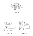
FIG. 4 is an enlarged view of the attachment portion of the turbine blade ofFIG. 3 ; -
FIG. 5 is a bottom view of a turbine blade in accordance with the present invention; -
FIG. 6 is a sectional view of the limiting section of the prior art turbine blade ofFIG. 1 ; -
FIG. 7 is a sectional view of the limiting section of a turbine blade ofFIG. 3 taken along lines 7 - 7; -
FIG. 8 is a sectional view of the limiting section illustrating the technique for providing an asymmetric root neck in accordance with the present invention; -
FIG. 9 is a perspective view of the turbine blade of the present invention illustrating the mechanism for dispersing strain at the root neck in accordance with the present invention; -
FIG. 10 illustrates the stresses acting on a prior art turbine blade; and -
FIG. 11 illustrates the stresses acting on a turbine blade in accordance with the present invention. - Referring now to the drawings,
FIGS. 3 through 5 illustrate aturbine blade 100 in accordance with the present invention. Theturbine blade 100 has aplatform 102, anairfoil 104 radially extending from afirst side 106 of theplatform 102, and an attachment orroot portion 108 extending from asecond side 110 of theplatform 102. Apocket structure 112 is formed in the sides of theplatform 102. Just below thepocket structure 112, there is aneck portion 114 that forms part of theroot portion 108. Theroot portion 108 also has adovetail portion 116 that is used to join theturbine blade 100 to a rotating member (not shown) such as a rotating disk. Theroot portion 108 has afront root face 111 and arear root face 122. - As can be best seen from
FIG. 5 , theairfoil 104 overhangs thefootprint 118 of theroot portion 108. Referring now to bothFIGS. 5 and9 , in order to avoid a concentration of stresses in theroot portion 108 of theturbine blade 100, stresses and strain which are caused by theoverhung airfoil 104 are dispersed over an increased area. One part of this increased area is formed byadditional material 120 along therear root face 122. Theadditional material 120 may be a cast material or a deposited material and may be the same material as the material forming theturbine blade 100 or may be a material which is compatible with the material forming theturbine blade 100. - As can be seen from
FIG. 9 , therear root face 122 has aplanar portion 125 extending from an edge or asurface 127. The leadingedge 129 of theadditional material 120 begins at a point spaced from thesurface 127. The leadingedge 129 is preferably arcuately spaced and extends from afirst side 133 of therear root face 122 to a second oropposite side 135 of therear root face 122. Theadditional material 120 increases in thickness as it goes from the leadingedge 129 to a point where it intersects thesecond side 110 of theplatform 102. This causes therear root face 122, at the point where it contacts theplatform 102 to have a curved, non-linearshape 137 as can be seen inFIG. 8 . - Additionally, if desired, the increased area for dispersing the stresses and strains may include a
compound fillet 124 beginning at apoint 139 at about 88% of the distance between the forwardfront root face 111 and thetrailing edge 128 of theplatform 102. Thecompound fillet 124 is preferably located on thehigher stress side 126 of theplatform 102. Typically, thehigher stress side 126 is the pressure side of the platform. Thecompound fillet 124 may be a cast structure formed from the same material as that forming theturbine blade 100 or may be a deposited material formed from the same material as, or from a different material compatible with, the material forming theturbine blade 100. Thecompound fillet 124 may be machined if desired. - The
root neck portion 114 preferably has a planar or substantiallyplanar portion 202 extending from thefront root face 111 to apoint 204 about midway of the distance from thefront root face 111 to thetrailing edge 128. The upper edge 200 then has an arcuatelyshaped transition zone 206 which extends from thepoint 204 to thestarting point 139 of thecompound fillet 124. As can be seen fromFIGS. 5 and9 , thecompound fillet 124 may then arcuately extend from thepoint 139 to a point near, or at, the intersection of thehigher stress side 126 of the platform and thetrailing edge 128 of the platform. Thecompound fillet 124 is three dimensional and rises from the planar surface of thesecond side 110 of theplatform 102 to anelevated ridge 210 where it intersects theadditional material 120. - As a result of the addition of the
additional material 120 and thecompound fillet 124, the load may be more dispersed between the pressure side andsuction side serrations root neck portion 114 is tapered axially producing increased root thickness towards the rear of theroot portion 108. This assists in reducing the stiffness in the center of theneck portion 114. - The
turbine blade 100 has a maximum stresslife limiting section 130 which is an uppermost section of theneck portion 114 just beneath theplatform 102. The stress concentrations caused by theoverhung airfoil 104 should be balanced between the lower stress side 132 (typically the suction side) and the higher stress side 134 (typically the pressure side) of the limitingsection 130. - In accordance with the present invention, the stress load may be redistributed by adjusting the moment of the volume above the limiting section center of gravity (CG) 140 relative to the peak
stress area CG 142 without adjusting the volume of the portion of theturbine blade 100 above the limitingsection 130. This is done by adjusting thearea CG 142 which affects the moment caused by the volume of the portion of the turbine blade above the limiting section. Increasing the moment to the lower stress side greatly reduces the stress on the higher or peak stress side. - The desired reduction in stress on the peak stress side may be accomplished by taking material away from the lower stress side (suction side) 144 of the limiting
section 130 and/or by adding material on the high stress side (pressure side) 146. This is illustrated inFIG. 8 and results in theneck portion 114 being asymmetric. The change in location of the cg ofarea 142 and the cg of volume above the limitingsection 140 can be seen inFIGS. 6 and 7 . It can be seen that the distance D2 between the cg ofvolume 140 and the cg ofarea 142 inFIG. 7 is greater than the distance D1 between cg ofvolume 140 and the cg ofarea 142 inFIG. 6 . This indicates the increase in moment to thelower stress side 144. - In one embodiment of the present invention, approximately 0.005 inches (0.127 mm)of material may be removed from the
side 144 in one or more benign stress areas. Further, additional material giving rise to an increase of 0.020 inches (0.508 mm) may be made to the higher stress orpressure side 146. The additional material may comprise a material which is identical to or compatible with the material forming theturbine blade 100 and may take the form of thecompound fillet 124 and thetransition zone 206 from the planar or substantiallyplanar portion 202 to thecompound fillet 124. As previously noted, this additional material may be a cast material or may be deposited after theturbine blade 100 has been formed. - In practicing the present invention, the material removal from the lower stress or
suction side 144 should be balanced with total P (force)/A (area) stress on theairfoil portion 104. Further, the bending moment is preferably moved more towards one side in such a way as to reduce the peak stress on the other side. - The asymmetric nature of the
neck portion 114 as a result of the aforementioned modifications is shown inFIG. 8 . Theasymmetric neck portion 114 of the present invention has particular utility on blades with broach angles. -
FIG. 10 illustrates the stresses on the pressure side of a prior art turbine blade, particularly at the pressure side castpocket 300.FIG. 11 illustrates the reduced stresses caused by the present invention. As can be seen fromFIG. 11 , the stress at the pressure side castpocket 300 has been reduced by 42%. The stress at the pressure side machinedfillet 302 has been reduced by 31%.
Claims (15)
- A method for providing a turbine blade (100) having balanced stress concentrations between suction and pressure sides (144,146) comprising the step of:forming a turbine blade having a platform (102), an attachment portion (108) having a neck portion (114) beneath the platform (102), and an airfoil portion (104) that extends radially from said platform (102) and overhangs the footprint (118) of the attachment portion (108), and a limiting section (130) at an uppermost section of the neck portion (114) just beneath the platform (102);adjusting a moment of volume above the limiting section centre of gravity (140) towards a lower stress side of the neck portion (114);wherein said adjusting step comprises removing material solely from the lower stress side of said limiting section (130) and/or adding material to the higher stress side of said neck portion (114).
- The method according to claim 1, wherein said adjusting step comprises taking material away from said lower stress side and adding material to said higher stress side of said neck portion (114) to thereby form an asymmetric neck portion.
- The method according to claim 2, wherein said adjusting step comprises taking material away from a suction side of said neck portion (114) and adding material to a pressure side of said neck portion (114).
- The method according to any preceding claim, further comprising dispersing strain in a region where the airfoil (104) overhangs the neck portion (114).
- The method according to claim 4, wherein said dispersing strain step comprises adding additional material (120) at a rear root face (122) of the attachment portion (108), wherein said rear root face (122) has a substantially planar portion (125) at a first end and said depositing step comprises adding said additional material (120) beginning at a point spaced from said first end, and wherein said adding step comprises adding said additional material (120) so said additional material increases in thickness from said point spaced from said first end to a surface of said platform (102).
- The method according to claim 4 or 5, wherein said dispersing strain step comprises forming a compound fillet (124) on a higher stress side trailing edge of a root of the attachment portion (108), wherein said forming step comprises forming a neck portion edge having a planar portion, an arcuately shaped transition portion (206) attached to said planar portion, and adding material at an end of said transition portion (206) to form said compound fillet (124), and wherein said forming step further comprises removing material from a lower stress side of said neck portion (114) so as to form an asymmetric net portion.
- A turbine blade (100) comprising:a platform (102);an attachment portion (108) comprising a root neck portion (114) having a higher stress side and a lower stress side;an airfoil (104) that radially extends from said platform (102) and overhang the footprint (118) of the attachment portion (108);a limiting section (130) at an uppermost section of the root neck portion (114) just beneath the platform (102);characterised in that:said root neck portion (114) is an asymmetric root neck portion (114) and adjusts a moment of volume above the limiting section center of gravity (140) relative to a peak stress area center of gravity towards the lower stress side of the asymmetric root neck portion (114); andsaid asymmetric root neck portion (114) is formed by material (120) added to said higher stress side of said neck portion (114) and/or removed material solely from a lower stress side of said neck portion (214).
- The turbine blade of claim 7, wherein said higher stress side comprises a pressure side and said lower stress side comprises a suction side.
- The turbine blade according to claims 7 or 8, wherein said attachment portion (108) has a forward root face (111) and said root neck portion (114) has an edge with a planar portion (202) extending from said forward root face (111), an arcuately shaped transition region (206) positioned adjacent an end of said forward root face, and a compound fillet (124) extending from an end of said transition region (206).
- The turbine blade according to claim 9, wherein said platform (102) has a trailing edge (128) and said compound fillet (124) has a curved surface which extends from said end of said transition region (206) to a point near an intersection of said higher pressure side (126) and said trailing edge (128), and wherein said compound fillet (124) increases in height from a point where said compound fillet (124) intersects a surface of said platform (102) and an elevated ridge (210).
- The turbine blade according to any of claims 7 to 10, further comprising means for dispersing strain in a region where said airfoil (104) overhangs said neck portion (114).
- The turbine blade according to claim 11, wherein said attachment portion (108) has a rear root face (122) and said strain dispersing means comprises additional material (120) formed on said rear root face (122), wherein said strain dispersing means further comprises a compound fillet (124) on an end portion of a higher pressure side of said platform (102), wherein said rear root face (122) has a planar portion (125) and said additional material has a leading edge (129) spaced from an edge of said planar portion (125), wherein said leading edge (129) is arcuately shaped, and wherein said additional material (120) increases in thickness from said leading edge (129) to a point adjacent a surface of said platform (102).
- The turbine blade according to claim 11, wherein said attachment portion (108) has a rear root face (122) and said strain dispersing means comprises additional material (120) on said rear root face (122).
- The turbine blade according to claim 13, wherein said rear root face (122) has a planar portion (125) beginning at a first end and said additional material (120) extends from a leading edge (129) spaced from said first end to a location where said additional material (120) intersects an underside of said platform (102) and wherein said additional material (120) increases in thickness from said leading edge to said location.
- The turbine blade according to claim 13 or 14, wherein said strain dispersing means further comprises a compound fillet (124) at a higher stress side trailing edge (128) of said attachment portion (108), wherein said compound fillet (124) has a ridge (210) and said compound fillet (124) increases in thickness from a point where said compound fillet (124) meets an underside of said platform (102) to said ridge (210), and wherein said attachment portion (108) has a planar section (202) and said strain dispersing means further comprises a curved transition section (206) between said planar section (202) and said compound fillet (124).
Applications Claiming Priority (1)
| Application Number | Priority Date | Filing Date | Title |
|---|---|---|---|
| US11/197,152 US7549846B2 (en) | 2005-08-03 | 2005-08-03 | Turbine blades |
Publications (3)
| Publication Number | Publication Date |
|---|---|
| EP1749968A2 EP1749968A2 (en) | 2007-02-07 |
| EP1749968A3 EP1749968A3 (en) | 2010-04-28 |
| EP1749968B1 true EP1749968B1 (en) | 2012-03-14 |
Family
ID=37397446
Family Applications (1)
| Application Number | Title | Priority Date | Filing Date |
|---|---|---|---|
| EP06253935A Active EP1749968B1 (en) | 2005-08-03 | 2006-07-27 | Turbine blades |
Country Status (6)
| Country | Link |
|---|---|
| US (1) | US7549846B2 (en) |
| EP (1) | EP1749968B1 (en) |
| JP (1) | JP2007040296A (en) |
| CN (1) | CN1908380A (en) |
| AU (1) | AU2006202238A1 (en) |
| SG (1) | SG130089A1 (en) |
Cited By (1)
| Publication number | Priority date | Publication date | Assignee | Title |
|---|---|---|---|---|
| US9353629B2 (en) | 2012-11-30 | 2016-05-31 | Solar Turbines Incorporated | Turbine blade apparatus |
Families Citing this family (19)
| Publication number | Priority date | Publication date | Assignee | Title |
|---|---|---|---|---|
| US20080317597A1 (en) * | 2007-06-25 | 2008-12-25 | General Electric Company | Domed tip cap and related method |
| USD611510S1 (en) * | 2007-08-28 | 2010-03-09 | Alstom Technology Ltd. | Turbo machine blade platform |
| USD586831S1 (en) * | 2007-08-28 | 2009-02-17 | Alstom Technology Ltd. | Turbo machine double blade and platform |
| US8122601B2 (en) * | 2008-04-15 | 2012-02-28 | United Technologies Corporation | Methods for correcting twist angle in a gas turbine engine blade |
| US9840931B2 (en) * | 2008-11-25 | 2017-12-12 | Ansaldo Energia Ip Uk Limited | Axial retention of a platform seal |
| US8608447B2 (en) * | 2009-02-19 | 2013-12-17 | Rolls-Royce Corporation | Disk for turbine engine |
| US8834123B2 (en) * | 2009-12-29 | 2014-09-16 | Rolls-Royce Corporation | Turbomachinery component |
| DE102010004854A1 (en) * | 2010-01-16 | 2011-07-21 | MTU Aero Engines GmbH, 80995 | Blade for a turbomachine and turbomachine |
| FR2963383B1 (en) * | 2010-07-27 | 2016-09-09 | Snecma | DUST OF TURBOMACHINE, ROTOR, LOW PRESSURE TURBINE AND TURBOMACHINE EQUIPPED WITH SUCH A DAWN |
| US9617860B2 (en) * | 2012-12-20 | 2017-04-11 | United Technologies Corporation | Fan blades for gas turbine engines with reduced stress concentration at leading edge |
| EP2971553B1 (en) | 2013-03-13 | 2019-11-13 | United Technologies Corporation | Rotor blade with a conic spline fillet at an intersection between a platform and a neck |
| EP2972604B1 (en) | 2013-03-15 | 2020-04-29 | United Technologies Corporation | Compact aero-thermo model based control system estimator starting algorithm |
| PL2818639T3 (en) * | 2013-06-27 | 2020-01-31 | MTU Aero Engines AG | Turbomachine rotor blade and corresponding turbomachine |
| FR3025563B1 (en) * | 2014-09-04 | 2019-04-05 | Safran Aircraft Engines | AUBE A PLATFORM AND EXCROIDANCE CREUSEE |
| FR3063514B1 (en) * | 2017-03-02 | 2019-04-12 | Safran | TURBOMACHINE BLADE AND METHOD FOR MANUFACTURING THE SAME |
| GB201800732D0 (en) * | 2018-01-17 | 2018-02-28 | Rolls Royce Plc | Blade for a gas turbine engine |
| JP7064076B2 (en) * | 2018-03-27 | 2022-05-10 | 三菱重工業株式会社 | How to tune turbine blades, turbines, and natural frequencies of turbine blades |
| JP6776465B1 (en) | 2020-01-27 | 2020-10-28 | 三菱パワー株式会社 | Turbine blade |
| JP7360971B2 (en) * | 2020-02-19 | 2023-10-13 | 三菱重工業株式会社 | Turbine blades and turbines |
Family Cites Families (15)
| Publication number | Priority date | Publication date | Assignee | Title |
|---|---|---|---|---|
| FR2556409B1 (en) | 1983-12-12 | 1991-07-12 | Gen Electric | IMPROVED BLADE FOR A GAS TURBINE ENGINE AND MANUFACTURING METHOD |
| WO1994012390A2 (en) | 1992-11-24 | 1994-06-09 | United Technologies Corporation | Coolable rotor blade structure |
| US5310318A (en) | 1993-07-21 | 1994-05-10 | General Electric Company | Asymmetric axial dovetail and rotor disk |
| US5435694A (en) * | 1993-11-19 | 1995-07-25 | General Electric Company | Stress relieving mount for an axial blade |
| US5492447A (en) * | 1994-10-06 | 1996-02-20 | General Electric Company | Laser shock peened rotor components for turbomachinery |
| US5836744A (en) * | 1997-04-24 | 1998-11-17 | United Technologies Corporation | Frangible fan blade |
| US6033185A (en) * | 1998-09-28 | 2000-03-07 | General Electric Company | Stress relieved dovetail |
| US6739837B2 (en) * | 2002-04-16 | 2004-05-25 | United Technologies Corporation | Bladed rotor with a tiered blade to hub interface |
| US6769877B2 (en) * | 2002-10-18 | 2004-08-03 | General Electric Company | Undercut leading edge for compressor blades and related method |
| US7121803B2 (en) * | 2002-12-26 | 2006-10-17 | General Electric Company | Compressor blade with dovetail slotted to reduce stress on the airfoil leading edge |
| US6902376B2 (en) * | 2002-12-26 | 2005-06-07 | General Electric Company | Compressor blade with dovetail slotted to reduce stress on the airfoil leading edge |
| US6805534B1 (en) | 2003-04-23 | 2004-10-19 | General Electric Company | Curved bucket aft shank walls for stress reduction |
| US6951447B2 (en) * | 2003-12-17 | 2005-10-04 | United Technologies Corporation | Turbine blade with trailing edge platform undercut |
| US7252481B2 (en) * | 2004-05-14 | 2007-08-07 | Pratt & Whitney Canada Corp. | Natural frequency tuning of gas turbine engine blades |
| US20060073022A1 (en) | 2004-10-05 | 2006-04-06 | Gentile David P | Frequency tailored thickness blade for a turbomachine wheel |
-
2005
- 2005-08-03 US US11/197,152 patent/US7549846B2/en active Active
-
2006
- 2006-05-26 AU AU2006202238A patent/AU2006202238A1/en not_active Abandoned
- 2006-06-01 SG SG200603737-8A patent/SG130089A1/en unknown
- 2006-06-02 JP JP2006154369A patent/JP2007040296A/en active Pending
- 2006-07-27 EP EP06253935A patent/EP1749968B1/en active Active
- 2006-08-03 CN CNA2006101111365A patent/CN1908380A/en active Pending
Cited By (1)
| Publication number | Priority date | Publication date | Assignee | Title |
|---|---|---|---|---|
| US9353629B2 (en) | 2012-11-30 | 2016-05-31 | Solar Turbines Incorporated | Turbine blade apparatus |
Also Published As
| Publication number | Publication date |
|---|---|
| JP2007040296A (en) | 2007-02-15 |
| CN1908380A (en) | 2007-02-07 |
| US20070031259A1 (en) | 2007-02-08 |
| EP1749968A2 (en) | 2007-02-07 |
| US7549846B2 (en) | 2009-06-23 |
| SG130089A1 (en) | 2007-03-20 |
| AU2006202238A1 (en) | 2007-02-22 |
| EP1749968A3 (en) | 2010-04-28 |
Similar Documents
| Publication | Publication Date | Title |
|---|---|---|
| US7549846B2 (en) | Turbine blades | |
| JP4942244B2 (en) | Curved compressor airfoil | |
| EP2362066B1 (en) | Hollow fan blade | |
| EP1980714B1 (en) | Rotor blade and corresponding turbine | |
| EP2372096B1 (en) | Composite fan blade dovetail root | |
| US6669445B2 (en) | Endwall shape for use in turbomachinery | |
| EP2372088B1 (en) | Turbofan flow path trenches | |
| US6524074B2 (en) | Gas turbine engine blade | |
| EP1813771B1 (en) | Bladed rotor assembly | |
| EP1270141A2 (en) | Method for repairing cracks in a turbine blade root trailing edge | |
| US8142165B2 (en) | Aerofoil | |
| EP2500524B1 (en) | Gas turbine engine blade and corresponding assemblage | |
| EP1118747A3 (en) | An aerofoil for an axial flow turbomachine | |
| EP4130430B1 (en) | Integrated bladed rotor | |
| EP2500525A1 (en) | Damper pin | |
| US7273353B2 (en) | Shroud honeycomb cutter | |
| JP2001132696A (en) | Stator blade with narrow waist | |
| CA2746415A1 (en) | Curved platform turbine blade | |
| US8801384B2 (en) | Airfoil attachment holding an airfoil root in a broach fitting | |
| US5425622A (en) | Turbine blade attachment means | |
| US9945232B2 (en) | Gas turbine blade configuration | |
| US8827654B2 (en) | Compressor blade of a gas-turbine engine with a self-sharpening leading-edge structure | |
| EP1818503B1 (en) | Turbine airfoil with weight reduction plenum | |
| EP1749970B1 (en) | Turbine airfoil platform extension for low buttress stress | |
| US9482099B2 (en) | Rotor blade for a turbomachine and turbomachine |
Legal Events
| Date | Code | Title | Description |
|---|---|---|---|
| PUAI | Public reference made under article 153(3) epc to a published international application that has entered the european phase |
Free format text: ORIGINAL CODE: 0009012 |
|
| AK | Designated contracting states |
Kind code of ref document: A2 Designated state(s): AT BE BG CH CY CZ DE DK EE ES FI FR GB GR HU IE IS IT LI LT LU LV MC NL PL PT RO SE SI SK TR |
|
| AX | Request for extension of the european patent |
Extension state: AL BA HR MK YU |
|
| PUAL | Search report despatched |
Free format text: ORIGINAL CODE: 0009013 |
|
| AK | Designated contracting states |
Kind code of ref document: A3 Designated state(s): AT BE BG CH CY CZ DE DK EE ES FI FR GB GR HU IE IS IT LI LT LU LV MC NL PL PT RO SE SI SK TR |
|
| AX | Request for extension of the european patent |
Extension state: AL BA HR MK RS |
|
| RIC1 | Information provided on ipc code assigned before grant |
Ipc: F01D 5/30 20060101AFI20100323BHEP |
|
| 17P | Request for examination filed |
Effective date: 20101027 |
|
| 17Q | First examination report despatched |
Effective date: 20101202 |
|
| AKX | Designation fees paid |
Designated state(s): DE GB |
|
| REG | Reference to a national code |
Ref country code: DE Ref legal event code: R079 Ref document number: 602006028146 Country of ref document: DE Free format text: PREVIOUS MAIN CLASS: F01D0005120000 Ipc: F01D0005300000 |
|
| RIC1 | Information provided on ipc code assigned before grant |
Ipc: F01D 5/30 20060101AFI20110630BHEP |
|
| GRAP | Despatch of communication of intention to grant a patent |
Free format text: ORIGINAL CODE: EPIDOSNIGR1 |
|
| GRAS | Grant fee paid |
Free format text: ORIGINAL CODE: EPIDOSNIGR3 |
|
| GRAA | (expected) grant |
Free format text: ORIGINAL CODE: 0009210 |
|
| AK | Designated contracting states |
Kind code of ref document: B1 Designated state(s): DE GB |
|
| REG | Reference to a national code |
Ref country code: GB Ref legal event code: FG4D |
|
| REG | Reference to a national code |
Ref country code: DE Ref legal event code: R081 Ref document number: 602006028146 Country of ref document: DE Owner name: UNITED TECHNOLOGIES CORP. (N.D.GES.D. STAATES , US Free format text: FORMER OWNER: UNITED TECHNOLOGIES CORP. (N.D.GES.D. STAATES DELAWARE), HARTFORD, CONN., US |
|
| REG | Reference to a national code |
Ref country code: DE Ref legal event code: R096 Ref document number: 602006028146 Country of ref document: DE Effective date: 20120510 |
|
| PLBE | No opposition filed within time limit |
Free format text: ORIGINAL CODE: 0009261 |
|
| STAA | Information on the status of an ep patent application or granted ep patent |
Free format text: STATUS: NO OPPOSITION FILED WITHIN TIME LIMIT |
|
| 26N | No opposition filed |
Effective date: 20121217 |
|
| REG | Reference to a national code |
Ref country code: DE Ref legal event code: R097 Ref document number: 602006028146 Country of ref document: DE Effective date: 20121217 |
|
| REG | Reference to a national code |
Ref country code: DE Ref legal event code: R082 Ref document number: 602006028146 Country of ref document: DE Representative=s name: SCHMITT-NILSON SCHRAUD WAIBEL WOHLFROM PATENTA, DE |
|
| REG | Reference to a national code |
Ref country code: DE Ref legal event code: R082 Ref document number: 602006028146 Country of ref document: DE Representative=s name: SCHMITT-NILSON SCHRAUD WAIBEL WOHLFROM PATENTA, DE Ref country code: DE Ref legal event code: R081 Ref document number: 602006028146 Country of ref document: DE Owner name: UNITED TECHNOLOGIES CORP. (N.D.GES.D. STAATES , US Free format text: FORMER OWNER: UNITED TECHNOLOGIES CORP., HARTFORD, CONN., US |
|
| PGFP | Annual fee paid to national office [announced via postgrant information from national office to epo] |
Ref country code: DE Payment date: 20190620 Year of fee payment: 14 |
|
| REG | Reference to a national code |
Ref country code: DE Ref legal event code: R119 Ref document number: 602006028146 Country of ref document: DE |
|
| PG25 | Lapsed in a contracting state [announced via postgrant information from national office to epo] |
Ref country code: DE Free format text: LAPSE BECAUSE OF NON-PAYMENT OF DUE FEES Effective date: 20210202 |
|
| PGFP | Annual fee paid to national office [announced via postgrant information from national office to epo] |
Ref country code: GB Payment date: 20250619 Year of fee payment: 20 |