EP1749726A2 - Drive force distribution device and method for distributing drive force - Google Patents
Drive force distribution device and method for distributing drive force Download PDFInfo
- Publication number
- EP1749726A2 EP1749726A2 EP06118275A EP06118275A EP1749726A2 EP 1749726 A2 EP1749726 A2 EP 1749726A2 EP 06118275 A EP06118275 A EP 06118275A EP 06118275 A EP06118275 A EP 06118275A EP 1749726 A2 EP1749726 A2 EP 1749726A2
- Authority
- EP
- European Patent Office
- Prior art keywords
- coupling
- heat generating
- temperature
- drive force
- transmission rate
- Prior art date
- Legal status (The legal status is an assumption and is not a legal conclusion. Google has not performed a legal analysis and makes no representation as to the accuracy of the status listed.)
- Granted
Links
Images

Classifications
-
- B—PERFORMING OPERATIONS; TRANSPORTING
- B60—VEHICLES IN GENERAL
- B60W—CONJOINT CONTROL OF VEHICLE SUB-UNITS OF DIFFERENT TYPE OR DIFFERENT FUNCTION; CONTROL SYSTEMS SPECIALLY ADAPTED FOR HYBRID VEHICLES; ROAD VEHICLE DRIVE CONTROL SYSTEMS FOR PURPOSES NOT RELATED TO THE CONTROL OF A PARTICULAR SUB-UNIT
- B60W30/00—Purposes of road vehicle drive control systems not related to the control of a particular sub-unit, e.g. of systems using conjoint control of vehicle sub-units
- B60W30/18—Propelling the vehicle
- B60W30/184—Preventing damage resulting from overload or excessive wear of the driveline
- B60W30/1843—Overheating of driveline components
-
- B—PERFORMING OPERATIONS; TRANSPORTING
- B60—VEHICLES IN GENERAL
- B60W—CONJOINT CONTROL OF VEHICLE SUB-UNITS OF DIFFERENT TYPE OR DIFFERENT FUNCTION; CONTROL SYSTEMS SPECIALLY ADAPTED FOR HYBRID VEHICLES; ROAD VEHICLE DRIVE CONTROL SYSTEMS FOR PURPOSES NOT RELATED TO THE CONTROL OF A PARTICULAR SUB-UNIT
- B60W2510/00—Input parameters relating to a particular sub-units
- B60W2510/02—Clutches
- B60W2510/0291—Clutch temperature
Definitions
- the present invention relates to a drive force distribution device and a method for distributing drive force.
- a typical drive force distribution device is capable of changing a drive force distribution ratio of a main drive wheel to a sub drive wheel.
- a torque coupling is provided in a drive force transmission system. Operation of the torque coupling is controlled in such a manner as to change the torque transmission rate (the transmitted torque) from an input to an outlet of the torque coupling. This regulates the drive force distribution ratio of the main drive wheel to the sub drive wheel.
- the torque coupling employs a friction clutch, which generates heat through frictional engagement of clutch plates. Also, a transfer case or a differential, which are arranged in the drive force transmission system of a vehicle, generate heat through friction caused by engagement of gears. Overheating of these heat generating portions thus must be suppressed.
- Japanese Laid-Open Patent Publication No. 2003-136990 describes a drive force distribution device that detects the temperatures of a differential or a transfer case provided in a drive force transmission system. If the temperature of the differential or the transfer case exceeds a corresponding predetermined level, the drive force distribution device controls operation of a torque coupling in such a manner as to suppress overheating of the differential or the transfer case.
- Japanese Laid-Open Patent Publication No. 7-12155 describes a method for estimating the temperature of a torque coupling in correspondence with the rotational speeds (difference of the rotational speeds) of an input shaft and an output shaft provided in the torque coupling, torque transmitted by the torque coupling, and the temperature of hydraulic fluid supplied to the torque coupling.
- a drive force distribution device of a vehicle including a main drive wheel, a sub drive wheel, and a drive force transmission system that transmits a drive force generated by a drive source to the drive wheels.
- the device includes a coupling and a control section.
- the coupling is arranged in the drive force transmission system.
- the coupling changes a torque transmission rate of a torque transmitted from an input of the coupling to an output of the coupling, thereby varying a drive force distribution ratio between the main drive wheel and the sub drive wheel.
- the control section controls operation of the coupling.
- the control section estimates a temperature of at least one of heat generating portions of the drive force transmission system in correspondence with a rotational speed of the heat generating portion, the torque transmission rate, and an outside temperature. If the estimated temperature exceeds a predetermined temperature, the control section controls the operation of the coupling to suppress overheating of the heat generating portion.
- a method for distributing drive force of a vehicle including a main drive wheel, a sub drive wheel, and a drive force transmission system that transmits a drive force generated by a drive source to the drive wheels is provided.
- the method includes: controlling operation of a coupling arranged in the drive force transmission system to vary a drive force distribution ratio between the main drive wheel and the sub drive wheel by changing a torque transmission rate of a torque transmitted from an input of the coupling to an output of the coupling; estimating a temperature of at least one of heat generating portions of the drive force transmission system in correspondence with the rotational speed of the heat generating portion, the torque transmission rate, and an outside temperature; determining whether the estimated temperature of at least one of the heat generating portions exceeds a corresponding predetermined temperature; and controlling the operation of the coupling to suppress overheating of the corresponding heat generating portion if the estimated temperature exceeds the predetermined temperature.
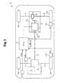
- a vehicle 1 is a front-wheel-drive based four-wheel-drive vehicle.
- the present invention is embodied as a drive force distribution device of a four-wheel-drive vehicle.
- a transaxle 3 is provided in an engine 2.
- a pair of front axles 4 and a propeller shaft 5 are connected to the transaxle 3.
- the propeller shaft 5 is also connected to a drive pinion shaft 7.
- the pinion shaft 7 is connected to a pair of rear axles 9 through a rear differential 8, or a differential.
- the drive force generated by the engine 2 is transmitted sequentially to the transaxle 3 and the front axle 4 in this order and then reaches front wheels 10f. Meanwhile, the drive force of the engine 2 is transmitted sequentially to the transaxle 3, the propeller shaft 5, the pinion shaft 7, the rear differential 8, and the rear axle 9 in this order and thus received by rear wheels 10r.
- the vehicle 1 includes a torque coupling 11 and an ECU 12.
- the torque coupling 11 is arranged in the above-described drive force transmission system.
- the torque coupling 11 changes the rate of the torque transmitted from the input to the outlet of the torque coupling 11 (the torque transmission rate). This alters the drive force distribution ratio of the front wheels 10f, which are main drive wheels, to the rear wheels 10r, or sub drive wheels.
- the ECU 12 functions as a control section that controls operation of the torque coupling 11.
- the torque coupling 11 and the ECU 12 form a drive force distribution device 13.
- the torque coupling 11 of the illustrated embodiment is arranged between the propeller shaft 5 and the pinion shaft 7. That is, the rear differential 8, or the differential, is provided between the torque coupling 11 and the rear wheels 10r, the sub drive wheels.
- the transaxle 3 includes a transfer case portion, which is arranged between the engine 2, or a drive source, and the torque coupling 11.
- the torque coupling 11, the pinion shaft 7, and the rear differential 8 are accommodated in a differential carrier 14.
- the torque coupling 11 has an electromagnetic clutch 15.
- the electromagnetic clutch 15 has a pair of clutch plates, or an input clutch plate and an output clutch plate, and an electromagnetic coil.
- the input clutch plate is connected to the propeller shaft 5 and the output clutch plate is connected to the pinion shaft 7.
- the force generated by friction engagement between the clutch plates changes in correspondence with the amount of the current supplied to the electromagnetic coil.
- the torque is caused in correspondence with the friction engagement force of the clutch plates.
- the electromagnetic clutch 15 transmits the torque from the input clutch plate to the outlet clutch plate.
- the ECU 12 controls operation of the torque coupling 11, or regulates the torque transmission rate. In this manner, the ECU 12 adjusts the drive force distribution ratio of the front wheels 10f, or the main drive wheels, to the rear wheels 10r, or the sub drive wheels.
- a throttle opening degree sensor 16 and wheel speed sensors 17f, 17r are connected to the ECU 12.
- the ECU 12 detects a throttle opening degree Ra, a vehicle speed V, and a wheel speed difference Wdiff, which is a difference between the wheel speed of each front wheel 10f and the wheel speed of each rear wheel 10r.
- the drive force distribution ratio is determined in correspondence with the detection results.
- the ECU 12 controls operation of the torque coupling 11 in such a manner as to adjust the torque transmission rate to a value corresponding to the determined drive force distribution ratio.
- the transaxle 3, the rear differential 8, and the torque coupling 11 are each a heat generating portion of the drive force transmission system.
- the drive force distribution device 13 suppresses overheating of the heat generating portions.
- predetermined temperatures T1, T2, and T0 are set for the transaxle 3, the rear differential 8, and the torque coupling 11, respectively. If at least one of the temperature Ttf of the transaxle 3, the temperature Tdf of the rear differential 8, and the temperature Ttc of the torque coupling 11 exceeds the corresponding temperature T1, T2, T0, operation of the torque coupling 11 is controlled to suppress overheating of the corresponding heat generating portion.
- the wheel speed sensors 17f, 17r and an outside temperature sensor 21 are connected to the ECU 12.
- the ECU 12 estimates the temperatures Ttf, Tdf, Ttc.
- the outside temperature sensor 21 is defined by a temperature sensor arranged in the vicinity of an outside air inlet for the air conditioning of the passenger compartment or an intake air temperature sensor installed in an intake pipe of the engine.
- the ECU 12 calculates the theoretical temperature H of each heat generating portion using the following equation (1) at predetermined sampling intervals (in step 101).
- H n K ⁇ 1 ⁇ ⁇ ⁇ K ⁇ 2 ⁇ Transmitted Torque ⁇ Rotational Speed ⁇ K ⁇ 3 ⁇ H ⁇ n ⁇ 1
- H(n-1) corresponds to a value obtained in a previous calculation cycle.
- K1, K2, and K3 are constants.
- the "rotational speed” is calculated from the front wheel speed Vf detected by the wheel speed sensor 17f and the rear wheel speed Vr detected by the wheel speed sensor 17r.
- the transaxle 3 is arranged between the engine 2, or the drive source, and the front wheels 10f, or the main drive wheels and between the engine 2 and the torque coupling 11.
- the rotational speed of the transaxle 3 is determined in correspondence with the front wheel speed Vf.
- the rotational speed of the rear differential 8 is determined in correspondence with the rear wheel speed Vr.
- the rotational speed (the differential rotational speed) of the torque coupling 11 is obtained from the difference between the front wheel speed Vf and the rear wheel speed Vr.
- the ECU 12 calculates a correction value ⁇ by which the theoretical temperatures H are corrected (in step 102).
- the ECU 12 stores a map 22 in which the correction value ⁇ is set in association with the outside temperature Tmp (see Fig. 3).
- the correction value ⁇ increases as the outside temperature Tmp rises.
- the ECU 12 obtains the correction value ⁇ corresponding to the detection value of the outside temperature Tmp from the map 22.
- the ECU 12 accumulates heat generating energy of each heat generating portion, which is calculated in correspondence with the rotational speed of the heat generating portion and the torque transmission rate. In this manner, heat energy accumulated in each heat generating portion, or the theoretical temperature H, is obtained. The ECU 12 then corrects the obtained value by canceling the influence (the cooling effect) by the outside temperature Tmp, thus estimating the temperatures Ttf, Tdf, Ttc of the heat generating portions.
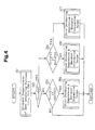
- the ECU 12 estimates the temperatures Ttf, Tdf, Ttc of the heat generating portions (in step 201 of Fig. 4). The ECU 12 then determines whether the estimated temperature Ttc of the torque coupling 11 exceeds the predetermined temperature T0 for the torque coupling 11 (in step 202). Subsequently, the ECU 12 determines whether the temperature Ttf of the transaxle 3 or the temperature Tdf of the rear differential 8 exceeds the respective predetermined temperature T1, T2 (in step 203 or step 204).
- the ECU 12 controls operation of the torque coupling 11 to reduce the torque transmission rate (in step 205, first overheating suppression A).
- the first overheating suppression A is performed by switching from a normal map by which the torque transmission rate, or the drive force distribution ratio of the front wheels 10f to the rear wheels 10r, is determined to an overheating suppression map that sets the torque transmission rate to lower values.
- the ECU 12 controls the operation of the torque coupling 11 to decrease the differential rotational speed between the propeller shaft 5, which is connected to the input clutch plate, and the pinion shaft 7, which is connected to the outlet clutch plate, or reduce the torque transmission rate.
- overheating of the torque coupling 11 is caused by frication engagement of the electromagnetic clutch 15.
- the friction heat generated by the electromagnetic clutch 15 varies in proportion to the product of the differential rotational speed and the torque transmission rate.
- the product of the differential rotational speed and the torque transmission rate is reduced to suppress the overheating of the torque coupling 11.
- the ECU 12 controls the operation of the torque coupling 11 to maximize the torque transmission rate of the torque coupling 11 (in step 206, second overheating suppression B).
- the ECU 12 controls the operation of the torque coupling 11 to minimize the torque transmission rate of the torque coupling 11 (in step 207, third overheating suppression C).
- the torque coupling 11 is fully engaged and the differential rotational speed of the torque coupling 11 becomes substantially zero. This suppresses generation of friction heat and thus effectively prevents overheating of the torque coupling 11.
- the illustrated embodiment has the following advantages.
- Estimation of the temperatures of the heat generating portions involves not only the rotational speed (the differential rotational speed) of each of the heat generating portion of the drive force transmission system and the torque transmission rate of the torque coupling 11 but also the outside temperature Tmp detected by the outside temperature sensor 21. If any of the estimated temperatures Ttf, Tdf, Ttc exceeds the respective predetermined temperature T1, T2, T0, the ECU 12 controls operation of the torque coupling 11 to suppress overheating of the heat generating portion(s).
- each heat generating portion is thus estimated through a simplified structure. Further, such estimation becomes further accurate compared to a case in which the temperature of each heat generating portion is estimated solely from the rotational speed of the heat generating portion and the torque transmission rate. Therefore, the procedure for suppressing overheating of the heat generating portions is performed further reliably. Overheating of each heat generating portion is thus effectively suppressed.
- the present invention is embodied as the drive force distribution device 13 of the vehicle 1 in which the front wheels 10f are defined as the main drive wheels.
- the invention may be applied to a drive force distribution device of a vehicle in which the rear wheels 10r are defined as the main drive wheels.
- the invention may be applied to a four-wheel drive device including a center differential device combined with an ECU or a device for distributing torque between front and rear wheels and/or right and left wheels.
- the theoretical temperature H of each of the heat generating portions is obtained from the equation (1) based on the rotational speed (the differential rotational speed) of the heat generating portion and the torque transmission rate of the torque coupling 11. Then, the correction value ⁇ is determined in correspondence with the outside temperature Tmp. The theoretical temperature H of each heat generating portion is thus corrected with the correction value ⁇ . In this manner, the temperatures Ttf, Tdf, Ttc of the heat generating portions are obtained. However, the temperatures Ttf, Tdf, Ttc of the heat generating portions may be estimated using an equation that includes the detected outside temperature Tmp as a parameter.
- the transaxle 3, the rear differential 8, and the torque coupling 11 correspond to the heat generating portions of the drive force transmission system.
- only at least one of the transaxle 3, the rear differential 8, and the torque coupling 11 may be defined as a heat generating portion, which is a target of suppression of overheating.
- An ECU (12) estimates the temperatures of the heat generating portions provided in a drive force transmission system, or a transaxle (3), a rear differential (8), and a torque coupling (11), in correspondence with not only the rotational speed (the differential rotational speed) of each heat generating portion and the torque transmission rate of the torque coupling (11) but also the outside temperature Tmp detected by an outside temperature sensor (21). If the estimated temperature of any of the heat generating portions exceeds a respective predetermined temperature, the ECU (12) controls operation of the torque coupling (11) to suppress overheating of the heat generating portion. That is, the temperature of each heat generating portion is accurately detected through a simplified structure and overheating of the heat generating portion is effectively suppressed (Fig. 1).
Landscapes
- Engineering & Computer Science (AREA)
- Automation & Control Theory (AREA)
- Transportation (AREA)
- Mechanical Engineering (AREA)
- Arrangement And Driving Of Transmission Devices (AREA)
- General Details Of Gearings (AREA)
Abstract
Description
- The present invention relates to a drive force distribution device and a method for distributing drive force.
- A typical drive force distribution device is capable of changing a drive force distribution ratio of a main drive wheel to a sub drive wheel. Typically, a torque coupling is provided in a drive force transmission system. Operation of the torque coupling is controlled in such a manner as to change the torque transmission rate (the transmitted torque) from an input to an outlet of the torque coupling. This regulates the drive force distribution ratio of the main drive wheel to the sub drive wheel.
- The torque coupling employs a friction clutch, which generates heat through frictional engagement of clutch plates. Also, a transfer case or a differential, which are arranged in the drive force transmission system of a vehicle, generate heat through friction caused by engagement of gears. Overheating of these heat generating portions thus must be suppressed.
- For example,
Japanese Laid-Open Patent Publication No. 2003-136990 - Alternatively,
Japanese Laid-Open Patent Publication No. 7-12155 - However, to provide temperature sensors in each of the heat generating portions, an increased cost is needed to prepare, assemble, and wire the parts. Further, to estimate the temperature of each heat generating portion based on the temperature of the hydraulic fluid supplied to the heat generating portion, the vehicle must have fluid temperature sensors that can detect the fluid temperatures in the heat generating portions.
- Accordingly, it is an objective of the present invention to provide a drive force distribution device and a method for distributing drive force that suppress overheating of the heat generating portion.
- To achieve the foregoing and other objectives and in accordance with one aspect of the present invention, a drive force distribution device of a vehicle including a main drive wheel, a sub drive wheel, and a drive force transmission system that transmits a drive force generated by a drive source to the drive wheels is provided. The device includes a coupling and a control section. The coupling is arranged in the drive force transmission system. The coupling changes a torque transmission rate of a torque transmitted from an input of the coupling to an output of the coupling, thereby varying a drive force distribution ratio between the main drive wheel and the sub drive wheel. The control section controls operation of the coupling. The control section estimates a temperature of at least one of heat generating portions of the drive force transmission system in correspondence with a rotational speed of the heat generating portion, the torque transmission rate, and an outside temperature. If the estimated temperature exceeds a predetermined temperature, the control section controls the operation of the coupling to suppress overheating of the heat generating portion.
- In accordance with a second aspect of the present invention, a method for distributing drive force of a vehicle including a main drive wheel, a sub drive wheel, and a drive force transmission system that transmits a drive force generated by a drive source to the drive wheels is provided. The method includes: controlling operation of a coupling arranged in the drive force transmission system to vary a drive force distribution ratio between the main drive wheel and the sub drive wheel by changing a torque transmission rate of a torque transmitted from an input of the coupling to an output of the coupling; estimating a temperature of at least one of heat generating portions of the drive force transmission system in correspondence with the rotational speed of the heat generating portion, the torque transmission rate, and an outside temperature; determining whether the estimated temperature of at least one of the heat generating portions exceeds a corresponding predetermined temperature; and controlling the operation of the coupling to suppress overheating of the corresponding heat generating portion if the estimated temperature exceeds the predetermined temperature.
- Other aspects and advantages of the invention will become apparent from the following description, taken in conjunction with the accompanying drawings, illustrating by way of example the principles of the invention.
- The invention, together with objects and advantages thereof, may best be understood by reference to the following description of the presently preferred embodiments together with the accompanying drawings in which:
- Fig. 1 is a diagram schematically showing the structure of a vehicle having a drive force distribution device according to one embodiment of the present invention;
- Fig. 2 is a flowchart representing a procedure for estimating temperatures of different heat generating portions of a drive force transmission system of the vehicle of Fig. 1;
- Fig. 3 is a map representing correction values associated with the outside temperature of the vehicle of Fig. 1; and
- Fig. 4 is a flowchart representing a control procedure for suppressing overheating of the drive force transmission system of Fig. 1.
- An embodiment of the present invention will now be described with reference to the attached drawings.
- As illustrated in Fig. 1, a vehicle 1 is a front-wheel-drive based four-wheel-drive vehicle. The present invention is embodied as a drive force distribution device of a four-wheel-drive vehicle. A transaxle 3 is provided in an
engine 2. A pair offront axles 4 and apropeller shaft 5 are connected to the transaxle 3. Thepropeller shaft 5 is also connected to a drive pinion shaft 7. The pinion shaft 7 is connected to a pair ofrear axles 9 through arear differential 8, or a differential. In other words, the drive force generated by theengine 2 is transmitted sequentially to the transaxle 3 and thefront axle 4 in this order and then reachesfront wheels 10f. Meanwhile, the drive force of theengine 2 is transmitted sequentially to the transaxle 3, thepropeller shaft 5, the pinion shaft 7, therear differential 8, and therear axle 9 in this order and thus received byrear wheels 10r. - In the illustrated embodiment, the vehicle 1 includes a torque coupling 11 and an
ECU 12. The torque coupling 11 is arranged in the above-described drive force transmission system. The torque coupling 11 changes the rate of the torque transmitted from the input to the outlet of the torque coupling 11 (the torque transmission rate). This alters the drive force distribution ratio of thefront wheels 10f, which are main drive wheels, to therear wheels 10r, or sub drive wheels. TheECU 12 functions as a control section that controls operation of the torque coupling 11. In the illustrated embodiment, the torque coupling 11 and theECU 12 form a driveforce distribution device 13. - Specifically, the torque coupling 11 of the illustrated embodiment is arranged between the
propeller shaft 5 and the pinion shaft 7. That is, therear differential 8, or the differential, is provided between the torque coupling 11 and therear wheels 10r, the sub drive wheels. The transaxle 3 includes a transfer case portion, which is arranged between theengine 2, or a drive source, and the torque coupling 11. The torque coupling 11, the pinion shaft 7, and therear differential 8 are accommodated in adifferential carrier 14. - In the present embodiment, the torque coupling 11 has an
electromagnetic clutch 15. Theelectromagnetic clutch 15 has a pair of clutch plates, or an input clutch plate and an output clutch plate, and an electromagnetic coil. The input clutch plate is connected to thepropeller shaft 5 and the output clutch plate is connected to the pinion shaft 7. The force generated by friction engagement between the clutch plates changes in correspondence with the amount of the current supplied to the electromagnetic coil. The torque is caused in correspondence with the friction engagement force of the clutch plates. Theelectromagnetic clutch 15 transmits the torque from the input clutch plate to the outlet clutch plate. By adjusting the amount of the current supplied to theelectromagnetic clutch 15, theECU 12 controls operation of the torque coupling 11, or regulates the torque transmission rate. In this manner, the ECU 12 adjusts the drive force distribution ratio of thefront wheels 10f, or the main drive wheels, to therear wheels 10r, or the sub drive wheels. - More specifically, in the illustrated embodiment, a throttle
opening degree sensor 16 andwheel speed sensors 17f, 17r are connected to theECU 12. In correspondence with signals provided by these sensors, the ECU 12 detects a throttle opening degree Ra, a vehicle speed V, and a wheel speed difference Wdiff, which is a difference between the wheel speed of eachfront wheel 10f and the wheel speed of eachrear wheel 10r. The drive force distribution ratio is determined in correspondence with the detection results. TheECU 12 controls operation of the torque coupling 11 in such a manner as to adjust the torque transmission rate to a value corresponding to the determined drive force distribution ratio. - Next, suppression of overheating by the drive force distribution device of the illustrated embodiment will be explained.
- The transaxle 3, the
rear differential 8, and the torque coupling 11 are each a heat generating portion of the drive force transmission system. The driveforce distribution device 13 suppresses overheating of the heat generating portions. In advance, predetermined temperatures T1, T2, and T0 are set for the transaxle 3, therear differential 8, and the torque coupling 11, respectively. If at least one of the temperature Ttf of the transaxle 3, the temperature Tdf of therear differential 8, and the temperature Ttc of the torque coupling 11 exceeds the corresponding temperature T1, T2, T0, operation of the torque coupling 11 is controlled to suppress overheating of the corresponding heat generating portion. - Specifically, in the illustrated embodiment, the
wheel speed sensors 17f, 17r and anoutside temperature sensor 21 are connected to theECU 12. In correspondence with the rotational speed (the differential rotational speed) of each of the heat generating portions, the torque transmission rate of the torque coupling 11, and the outside temperature Tmp detected by theoutside temperature 21, theECU 12 estimates the temperatures Ttf, Tdf, Ttc. Theoutside temperature sensor 21 is defined by a temperature sensor arranged in the vicinity of an outside air inlet for the air conditioning of the passenger compartment or an intake air temperature sensor installed in an intake pipe of the engine. - More specifically, as indicated by the flowchart of Fig. 2, the
ECU 12 calculates the theoretical temperature H of each heat generating portion using the following equation (1) at predetermined sampling intervals (in step 101).
- In the equation (1), H(n-1) corresponds to a value obtained in a previous calculation cycle. K1, K2, and K3 are constants. By setting the constants K1, K2, K3 in correspondence with the heat generating portions, the theoretical temperatures H (Htf, Hdf, Htc) of the heat generating portions are obtained. The "rotational speed" is calculated from the front wheel speed Vf detected by the wheel speed sensor 17f and the rear wheel speed Vr detected by the
wheel speed sensor 17r. The transaxle 3 is arranged between theengine 2, or the drive source, and thefront wheels 10f, or the main drive wheels and between theengine 2 and the torque coupling 11. Thus, the rotational speed of the transaxle 3 is determined in correspondence with the front wheel speed Vf. Since therear differential 8 is arranged between the torque coupling 11 and therear wheels 10r, or the sub drive wheels, the rotational speed of therear differential 8 is determined in correspondence with the rear wheel speed Vr. The rotational speed (the differential rotational speed) of the torque coupling 11 is obtained from the difference between the front wheel speed Vf and the rear wheel speed Vr. - Subsequently, in correspondence with a detection value of the outside temperature Tmp, the
ECU 12 calculates a correction value α by which the theoretical temperatures H are corrected (in step 102). In the illustrated embodiment, theECU 12 stores amap 22 in which the correction value α is set in association with the outside temperature Tmp (see Fig. 3). In accordance with themap 22, the correction value α increases as the outside temperature Tmp rises. TheECU 12 obtains the correction value α corresponding to the detection value of the outside temperature Tmp from themap 22. - Next, using the correction value α associated with the outside temperature Tmp, the
ECU 12 corrects the theoretical temperatures H, which have been obtained from the equation (1) (Tx=Hx+α, x=tf, df, tc). In this manner, the temperatures Ttf, Tdf, Ttc of the heat generating portions are estimated (in step 103). - In other words, in the illustrated embodiment, the
ECU 12 accumulates heat generating energy of each heat generating portion, which is calculated in correspondence with the rotational speed of the heat generating portion and the torque transmission rate. In this manner, heat energy accumulated in each heat generating portion, or the theoretical temperature H, is obtained. TheECU 12 then corrects the obtained value by canceling the influence (the cooling effect) by the outside temperature Tmp, thus estimating the temperatures Ttf, Tdf, Ttc of the heat generating portions. - A control procedure for suppressing overheating will hereafter be explained in detail.
- First, as indicated by the flowchart of Fig. 4, the
ECU 12 estimates the temperatures Ttf, Tdf, Ttc of the heat generating portions (instep 201 of Fig. 4). TheECU 12 then determines whether the estimated temperature Ttc of the torque coupling 11 exceeds the predetermined temperature T0 for the torque coupling 11 (in step 202). Subsequently, theECU 12 determines whether the temperature Ttf of the transaxle 3 or the temperature Tdf of therear differential 8 exceeds the respective predetermined temperature T1, T2 (instep 203 or step 204). - If it is determined that the temperature Ttc of the torque coupling 11 is not more than the predetermined temperature T0 (Ttc ≤ T0, NO in step 202) and at least one of the temperature Ttf of the transaxle 3 and the temperature Tdf of the
rear differential 8 exceeds the predetermined temperature T1, T2 (Ttf > T1 or Tdf > T2, YES in step 203), theECU 12 controls operation of the torque coupling 11 to reduce the torque transmission rate (instep 205, first overheating suppression A). - Specifically, heat generation in the transaxle 3 and the
rear differential 8 becomes significantly great when the drive force is distributed dominantly to therear wheels 10r, or the sub drive wheels. Thus, by decreasing the torque transmission rate of the torque coupling 11 and reducing the load applied to the transaxle 3 and therear differential 8, overheating of the transaxle 3 and therear differential 8 can be suppressed. In the illustrated embodiment, the first overheating suppression A is performed by switching from a normal map by which the torque transmission rate, or the drive force distribution ratio of thefront wheels 10f to therear wheels 10r, is determined to an overheating suppression map that sets the torque transmission rate to lower values. - If it is determined that the temperature Ttc of the torque coupling 11 exceeds the predetermined temperature T0 in step 202 (Ttc > T0, YES in step 202), the
ECU 12 controls the operation of the torque coupling 11 to decrease the differential rotational speed between thepropeller shaft 5, which is connected to the input clutch plate, and the pinion shaft 7, which is connected to the outlet clutch plate, or reduce the torque transmission rate. - Specifically, overheating of the torque coupling 11 is caused by frication engagement of the
electromagnetic clutch 15. The friction heat generated by theelectromagnetic clutch 15 varies in proportion to the product of the differential rotational speed and the torque transmission rate. Thus, by decreasing at least one of the differential rotational speed and the torque transmission rate, the product of the differential rotational speed and the torque transmission rate is reduced to suppress the overheating of the torque coupling 11. - More specifically, if it is determined that the temperature Ttf of the transaxle 3 is not more than the predetermined temperature T1 and the temperature Tdf of the
rear differential 8 is not more than the predetermined temperature T2 in step 204 (Ttf ≤ T1 and Tdf ≤ T2, NO in step 204), theECU 12 controls the operation of the torque coupling 11 to maximize the torque transmission rate of the torque coupling 11 (instep 206, second overheating suppression B). - If it is determined that at least one of the temperature Ttf of the transaxle 3 and the temperature Tdf of the
rear differential 8 exceeds the corresponding predetermined temperature T1, T2 in step 204 (Ttf > T1 or Tdf > T2, YES in step 204), theECU 12 controls the operation of the torque coupling 11 to minimize the torque transmission rate of the torque coupling 11 (instep 207, third overheating suppression C). - Specifically, by maximizing the torque transmission rate, the torque coupling 11 is fully engaged and the differential rotational speed of the torque coupling 11 becomes substantially zero. This suppresses generation of friction heat and thus effectively prevents overheating of the torque coupling 11.
- However, if the torque transmission rate of the torque coupling 11, or the drive force distributed to the
rear wheels 10r, or the sub drive wheels, is maximized, the load acting on the transaxle 3 and therear differential 8 increases. This may lead to overheating of the transaxle 3 and therear differential 8. Therefore, in the illustrated embodiment, if the overheating of the transaxle 3 and therear differential 8 becomes likely in addition to likeliness of the overheating of the torque coupling 11, the torque transmission rate of the torque coupling 11 is minimized. That is, the drive force distributed to therear wheels 10r becomes substantially zero, thus disengaging theelectromagnetic clutch 15. This suppresses heat generation by theelectromagnetic clutch 15 and minimizes the load acting on the transaxle 3 and therear differential 8. Accordingly, overheating of each of the heat generating portions is effectively suppressed. - The illustrated embodiment has the following advantages.
- Estimation of the temperatures of the heat generating portions (the temperature Ttf of the transaxle 3, the temperature Tdf of the
rear differential 8, and the temperature Ttc of the torque coupling 11) by theECU 12 involves not only the rotational speed (the differential rotational speed) of each of the heat generating portion of the drive force transmission system and the torque transmission rate of the torque coupling 11 but also the outside temperature Tmp detected by theoutside temperature sensor 21. If any of the estimated temperatures Ttf, Tdf, Ttc exceeds the respective predetermined temperature T1, T2, T0, theECU 12 controls operation of the torque coupling 11 to suppress overheating of the heat generating portion(s). - This makes it unnecessary to install a temperature sensor or a fluid temperature sensor in each of the heat generating portions. The temperature of each heat generating portion is thus estimated through a simplified structure. Further, such estimation becomes further accurate compared to a case in which the temperature of each heat generating portion is estimated solely from the rotational speed of the heat generating portion and the torque transmission rate. Therefore, the procedure for suppressing overheating of the heat generating portions is performed further reliably. Overheating of each heat generating portion is thus effectively suppressed.
- It should be apparent to those skilled in the art that the present invention may be embodied in many other specific forms without departing from the spirit or scope of the invention. Particularly, it should be understood that the invention may be embodied in the following forms.
- In the illustrated embodiment, the present invention is embodied as the drive
force distribution device 13 of the vehicle 1 in which thefront wheels 10f are defined as the main drive wheels. However, the invention may be applied to a drive force distribution device of a vehicle in which therear wheels 10r are defined as the main drive wheels. Alternatively, the invention may be applied to a four-wheel drive device including a center differential device combined with an ECU or a device for distributing torque between front and rear wheels and/or right and left wheels. - In the illustrated embodiment, the theoretical temperature H of each of the heat generating portions is obtained from the equation (1) based on the rotational speed (the differential rotational speed) of the heat generating portion and the torque transmission rate of the torque coupling 11. Then, the correction value α is determined in correspondence with the outside temperature Tmp. The theoretical temperature H of each heat generating portion is thus corrected with the correction value α. In this manner, the temperatures Ttf, Tdf, Ttc of the heat generating portions are obtained. However, the temperatures Ttf, Tdf, Ttc of the heat generating portions may be estimated using an equation that includes the detected outside temperature Tmp as a parameter.
- In the illustrated embodiment, the transaxle 3, the
rear differential 8, and the torque coupling 11 correspond to the heat generating portions of the drive force transmission system. However, only at least one of the transaxle 3, therear differential 8, and the torque coupling 11 may be defined as a heat generating portion, which is a target of suppression of overheating. - Therefore, the present examples and embodiments are to be considered as illustrative and not restrictive and the invention is not to be limited to the details given herein, but may be modified within the scope and equivalence of the appended claims.
- An ECU (12) estimates the temperatures of the heat generating portions provided in a drive force transmission system, or a transaxle (3), a rear differential (8), and a torque coupling (11), in correspondence with not only the rotational speed (the differential rotational speed) of each heat generating portion and the torque transmission rate of the torque coupling (11) but also the outside temperature Tmp detected by an outside temperature sensor (21). If the estimated temperature of any of the heat generating portions exceeds a respective predetermined temperature, the ECU (12) controls operation of the torque coupling (11) to suppress overheating of the heat generating portion. That is, the temperature of each heat generating portion is accurately detected through a simplified structure and overheating of the heat generating portion is effectively suppressed (Fig. 1).
Claims (10)
- A drive force distribution device of a vehicle including a main drive wheel (10f), a sub drive wheel (10r), and a drive force transmission system that transmits a drive force generated by a drive source (2) to the drive wheels (10f, 10r), the device comprising:a coupling (11) arranged in the drive force transmission system, wherein the coupling (11) changes a torque transmission rate of a torque transmitted from an input (5) of the coupling (11) to an output (7) of the coupling (11), thereby varying a drive force distribution ratio between the main drive wheel (10f) and the sub drive wheel (10r); anda control section (12) that controls operation of the coupling (11),the device being characterized in thatthe control section (12) estimating a temperature (Ttf, Tdf, Ttc) of at least one of heat generating portions (3, 8, 11) of the drive force transmission system in correspondence with a rotational speed of the heat generating portion (3, 8, 11), the torque transmission rate, and an outside temperature (Tmp), wherein, if the estimated temperature (Ttf, Tdf, Ttc) exceeds a predetermined temperature (T1, T2, T0), the control section (12) controls the operation of the coupling (11) to suppress overheating of the heat generating portion (3, 8, 11).
- The device according to claim 1, characterized in that:the heat generating portions include at least one of a differential (8) and a transfer case (3), the differential (8) being arranged between the coupling (11) and the sub drive wheel (10r), the transfer case (3) being provided between the drive source (2) and the coupling (11) and between the drive source (2) and the main drive wheel (10f); andthe control section (12) controls the operation of the coupling (11) to decrease the torque transmission rate if the estimated temperature (Ttf, Tdf) exceeds the predetermined temperature (T1, T2) (S205).
- The device according to claim 1 or 2,
characterized in that:the heat generating portions include the coupling (11); andif the estimated temperature (Ttc) of the coupling (11) exceeds the predetermined temperature (T0), the control section (12) controls the operation of the coupling (11) to decrease at least one of a differential rotational speed between the input (5) and the output (7) (S206) and the torque transmission rate (S207). - The device according to claim 3, characterized in that:if the estimated temperature (Ttc) of the coupling (11) exceeds the predetermined temperature (T0), the control section (12) controls the operation of the coupling (11) to maximize the torque transmission rate (S206).
- The device according to claim 4, characterized in that:if the estimated temperature (Ttc) of the coupling (11) exceeds the predetermined temperature (T0) and the estimated temperature (Ttf, Tdf) of at least one of the heat generating portions (3, 8) other than the coupling (11) exceeds the predetermined temperature (T1, T2), the control section (12) controls the operation of the coupling (11) to minimize the torque transmission rate (S207).
- A method for distributing drive force of a vehicle including a main drive wheel (10f), a sub drive wheel (10r), and a drive force transmission system that transmits a drive force generated by a drive source (2) to the drive wheels (10f, 10r), the method comprising:controlling operation of a coupling (11) arranged in the drive force transmission system to vary a drive force distribution ratio between the main drive wheel (10f) and the sub drive wheel (10r) by changing a torque transmission rate of a torque transmitted from an input (5) of the coupling (11) to an output (7) of the coupling (11),the method being characterized by:estimating a temperature (Ttf, Tdf, Ttc) of at least one of heat generating portions (3, 8, 11) of the drive force transmission system in correspondence with the rotational speed of the heat generating portion (3, 8, 11), the torque transmission rate, and an outside temperature (Tmp);determining whether the estimated temperature (Ttf, Tdf, Ttc) of at least one of the heat generating portions (3, 8, 11) exceeds a corresponding predetermined temperature (T1, T2, T0); andcontrolling the operation of the coupling (11) to suppress overheating of the corresponding heat generating portion (3, 8, 11) if the estimated temperature (Ttf, Tdf, Ttc) exceeds the predetermined temperature (T1, T2, T0).
- The method according to claim 6, characterized by:estimating a temperature (Tdf, Ttf) of at least one of a differential (8) and a transfer case (3) as the heat generating portion, the differential (8) being arranged between the coupling (11) and the sub drive wheel (10r), the transfer case (3) being provided between the drive source (2) and the coupling (11) and between the drive source (2) and the main drive wheel (10f); andcontrolling the operation of the coupling (11) to decrease the torque transmission rate if the estimated temperature (Ttf, Tdf) exceeds the predetermined temperature (T1, T2) (S205).
- The method according to claim 6 or 7,
characterized by:estimating the temperature (Ttc) of the coupling (11) as the heat generating portion; andcontrolling the operation of the coupling (11) to decrease at least one of a differential rotational speed between the input (5) and the output (7) (S206) and the torque transmission rate (S207) if the estimated temperature (Ttc) exceeds the predetermined temperature (T0) of the coupling (11). - The method according to claim 8, characterized by:controlling the operation of the coupling (11) to maximize the torque transmission rate if the estimated temperature (Ttc) of the coupling (11) exceeds the predetermined temperature (T0) (S206).
- The device according to claim 9, characterized by:controlling the operation of the coupling (11) to minimize the torque transmission rate if the estimated temperature (Ttc) of the coupling (11) exceeds the predetermined temperature (T0) and the estimated temperature (Ttf, Tdf) of at least one of the heat generating portions (3, 8) other than the coupling (11) exceeds the predetermined temperature (T1, T2) (S207).
Applications Claiming Priority (1)
| Application Number | Priority Date | Filing Date | Title |
|---|---|---|---|
| JP2005224299A JP4551291B2 (en) | 2005-08-02 | 2005-08-02 | Driving force distribution device |
Publications (3)
| Publication Number | Publication Date |
|---|---|
| EP1749726A2 true EP1749726A2 (en) | 2007-02-07 |
| EP1749726A3 EP1749726A3 (en) | 2007-07-04 |
| EP1749726B1 EP1749726B1 (en) | 2009-04-15 |
Family
ID=37400948
Family Applications (1)
| Application Number | Title | Priority Date | Filing Date |
|---|---|---|---|
| EP06118275A Ceased EP1749726B1 (en) | 2005-08-02 | 2006-08-01 | Drive force distribution device and method for distributing drive force |
Country Status (4)
| Country | Link |
|---|---|
| US (1) | US7553257B2 (en) |
| EP (1) | EP1749726B1 (en) |
| JP (1) | JP4551291B2 (en) |
| DE (1) | DE602006006258D1 (en) |
Cited By (3)
| Publication number | Priority date | Publication date | Assignee | Title |
|---|---|---|---|---|
| FR2933913A1 (en) * | 2008-07-16 | 2010-01-22 | Renault Sas | CONTROL DEVICE ADAPTIVE TO THE EVOLUTION OF THE CHARACTERISTIC OF A CLUTCH BASED ON THE TEMPERATURE APPLIED TO A VEHICLE EQUIPPED WITH A 4X4 PILOT SYSTEM. |
| GB2470013A (en) * | 2009-05-05 | 2010-11-10 | Gm Global Tech Operations Inc | Synchronizer control using estimated heating power released by friction surfaces |
| EP4015325A4 (en) * | 2019-10-31 | 2022-11-02 | Great Wall Motor Company Limited | INTELLIGENT FOUR-WHEEL DRIVE CONTROL METHOD AND SYSTEM, AND VEHICLE |
Families Citing this family (14)
| Publication number | Priority date | Publication date | Assignee | Title |
|---|---|---|---|---|
| US7575860B2 (en) * | 2000-03-07 | 2009-08-18 | Evans David H | DNA joining method |
| JP4551291B2 (en) | 2005-08-02 | 2010-09-22 | 株式会社ジェイテクト | Driving force distribution device |
| JP4542964B2 (en) * | 2005-08-02 | 2010-09-15 | 株式会社ジェイテクト | Driving force distribution device |
| JP4848914B2 (en) * | 2006-09-29 | 2011-12-28 | トヨタ自動車株式会社 | Control device for torque transmission mechanism, control method, program for realizing the control method, and recording medium recording the program |
| JP5012400B2 (en) * | 2007-10-18 | 2012-08-29 | 株式会社ジェイテクト | Driving force transmission device |
| US7789794B2 (en) * | 2007-10-23 | 2010-09-07 | Ford Global Technologies, Llc | Method and system for controlling a propulsion system of an alternatively powered vehicle |
| JP5067243B2 (en) * | 2008-03-31 | 2012-11-07 | 株式会社ジェイテクト | Driving force transmission device, driving force transmission device control method, and differential limiting device |
| US8185285B2 (en) * | 2008-04-08 | 2012-05-22 | GM Global Technology Operations LLC | Transmission hydraulic pressure sensor based altitude measurement |
| JP5277812B2 (en) * | 2008-09-11 | 2013-08-28 | 株式会社ジェイテクト | Driving force distribution device and control method of driving force distribution device |
| US20110218723A1 (en) * | 2008-09-25 | 2011-09-08 | Andreas Erban | Method for producing a vehicle difference moment |
| JP5278187B2 (en) * | 2009-06-18 | 2013-09-04 | トヨタ自動車株式会社 | VEHICLE CONTROL DEVICE AND VEHICLE CONTROL METHOD |
| GB2488525A (en) * | 2011-02-18 | 2012-09-05 | Land Rover Uk Ltd | Vehicle having an auxiliary driveline with a temperature responsive clutch |
| JP6769399B2 (en) * | 2017-06-16 | 2020-10-14 | トヨタ自動車株式会社 | Vehicle driving force distribution device |
| FR3138639A1 (en) * | 2022-08-02 | 2024-02-09 | Psa Automobiles Sa | METHOD FOR CONTROLLING AN ELECTRIC OR HYBRID VEHICLE TRACTION CHAIN |
Citations (4)
| Publication number | Priority date | Publication date | Assignee | Title |
|---|---|---|---|---|
| JPH0712155A (en) | 1993-06-25 | 1995-01-17 | Komatsu Ltd | Method and device for preventing damage to wet friction transmission device |
| WO2002025133A1 (en) | 2000-09-19 | 2002-03-28 | Nissan Motor Co.,Ltd. | Apparatus for estimating clutch temperature |
| EP1270305A2 (en) | 2001-06-26 | 2003-01-02 | Nissan Motor Company, Limited | Driving force controlling apparatus and method for four-wheel drive vehicle |
| EP1308338A2 (en) | 2001-10-31 | 2003-05-07 | Toyoda Koki Kabushiki Kaisha | Power distribution method and power distribution control apparatus for vehicle |
Family Cites Families (20)
| Publication number | Priority date | Publication date | Assignee | Title |
|---|---|---|---|---|
| JPH0759886B2 (en) | 1985-10-21 | 1995-06-28 | 本田技研工業株式会社 | Engine cooling system |
| US5623914A (en) | 1994-05-09 | 1997-04-29 | Nissan Motor Co., Ltd. | Air/fuel ratio control apparatus |
| JP3602599B2 (en) * | 1995-03-02 | 2004-12-15 | 本田技研工業株式会社 | Control device for hydraulically operated transmission for vehicles |
| JP3035185B2 (en) * | 1995-03-02 | 2000-04-17 | 本田技研工業株式会社 | Control device for hydraulically operated transmission for vehicles |
| DE19625889A1 (en) | 1996-06-27 | 1998-01-02 | Bayerische Motoren Werke Ag | Method for model-based simulation of the coolant temperature in a vehicle |
| JP3570214B2 (en) * | 1998-03-31 | 2004-09-29 | トヨタ自動車株式会社 | Temperature estimation device for frictional engagement device for vehicle |
| JP3596433B2 (en) | 2000-06-29 | 2004-12-02 | 株式会社デンソー | Automotive electronic control unit |
| US7077783B2 (en) * | 2000-09-15 | 2006-07-18 | Robert Bosch Gmbh | Method and device for operating a clutch |
| JP3575429B2 (en) * | 2000-09-19 | 2004-10-13 | 日産自動車株式会社 | Front and rear wheel torque distribution control device for four-wheel drive vehicle |
| KR100380493B1 (en) * | 2000-12-28 | 2003-04-18 | 현대자동차주식회사 | control method of damper clutch for automatic transmission |
| JP3988405B2 (en) * | 2001-05-28 | 2007-10-10 | 株式会社ジェイテクト | Driving force transmission control device, program, and recording medium |
| JP3775245B2 (en) | 2001-06-11 | 2006-05-17 | コベルコ建機株式会社 | Pump controller for construction machinery |
| JP3857568B2 (en) * | 2001-10-31 | 2006-12-13 | 株式会社ジェイテクト | Driving force distribution control device for four-wheel drive vehicle |
| JP2003327001A (en) * | 2002-05-15 | 2003-11-19 | Toyota Motor Corp | Car |
| JP2004092570A (en) * | 2002-09-02 | 2004-03-25 | Toyoda Mach Works Ltd | Driving force transmission/control device |
| JP4317716B2 (en) * | 2003-07-08 | 2009-08-19 | 株式会社ジェイテクト | Driving force distribution control device for four-wheel drive vehicle |
| JP4105086B2 (en) | 2003-12-22 | 2008-06-18 | 本田技研工業株式会社 | Temperature sensor failure diagnosis device |
| JP4131253B2 (en) * | 2004-06-10 | 2008-08-13 | 日産自動車株式会社 | Vehicle starting friction element control device |
| JP4529555B2 (en) | 2004-06-22 | 2010-08-25 | 日産自動車株式会社 | Control device for vehicle generator |
| JP4551291B2 (en) | 2005-08-02 | 2010-09-22 | 株式会社ジェイテクト | Driving force distribution device |
-
2005
- 2005-08-02 JP JP2005224299A patent/JP4551291B2/en not_active Expired - Fee Related
-
2006
- 2006-08-01 EP EP06118275A patent/EP1749726B1/en not_active Ceased
- 2006-08-01 US US11/496,515 patent/US7553257B2/en active Active
- 2006-08-01 DE DE602006006258T patent/DE602006006258D1/en active Active
Patent Citations (4)
| Publication number | Priority date | Publication date | Assignee | Title |
|---|---|---|---|---|
| JPH0712155A (en) | 1993-06-25 | 1995-01-17 | Komatsu Ltd | Method and device for preventing damage to wet friction transmission device |
| WO2002025133A1 (en) | 2000-09-19 | 2002-03-28 | Nissan Motor Co.,Ltd. | Apparatus for estimating clutch temperature |
| EP1270305A2 (en) | 2001-06-26 | 2003-01-02 | Nissan Motor Company, Limited | Driving force controlling apparatus and method for four-wheel drive vehicle |
| EP1308338A2 (en) | 2001-10-31 | 2003-05-07 | Toyoda Koki Kabushiki Kaisha | Power distribution method and power distribution control apparatus for vehicle |
Cited By (4)
| Publication number | Priority date | Publication date | Assignee | Title |
|---|---|---|---|---|
| FR2933913A1 (en) * | 2008-07-16 | 2010-01-22 | Renault Sas | CONTROL DEVICE ADAPTIVE TO THE EVOLUTION OF THE CHARACTERISTIC OF A CLUTCH BASED ON THE TEMPERATURE APPLIED TO A VEHICLE EQUIPPED WITH A 4X4 PILOT SYSTEM. |
| WO2010007271A3 (en) * | 2008-07-16 | 2010-03-11 | Renault S.A.S. | Control device adapted to the change in the characteristic of a clutch as a function of temperature as applied to a vehicle fitted with a controlled 4x4 system |
| GB2470013A (en) * | 2009-05-05 | 2010-11-10 | Gm Global Tech Operations Inc | Synchronizer control using estimated heating power released by friction surfaces |
| EP4015325A4 (en) * | 2019-10-31 | 2022-11-02 | Great Wall Motor Company Limited | INTELLIGENT FOUR-WHEEL DRIVE CONTROL METHOD AND SYSTEM, AND VEHICLE |
Also Published As
| Publication number | Publication date |
|---|---|
| US20070032339A1 (en) | 2007-02-08 |
| JP4551291B2 (en) | 2010-09-22 |
| EP1749726A3 (en) | 2007-07-04 |
| DE602006006258D1 (en) | 2009-05-28 |
| US7553257B2 (en) | 2009-06-30 |
| JP2007038797A (en) | 2007-02-15 |
| EP1749726B1 (en) | 2009-04-15 |
Similar Documents
| Publication | Publication Date | Title |
|---|---|---|
| EP1749726B1 (en) | Drive force distribution device and method for distributing drive force | |
| US7234553B2 (en) | Vehicle driving force control apparatus | |
| US8135517B2 (en) | Torque control method of a road vehicle | |
| US7140459B2 (en) | Vehicle driving force control apparatus | |
| US6902511B2 (en) | Vehicle driving force control apparatus | |
| EP1319137B1 (en) | Apparatus for estimating clutch temperature | |
| KR0165149B1 (en) | Clutch controlling apparatus for vehicles | |
| EP1740432B1 (en) | Model-based control for torque biasing system | |
| EP1749725B1 (en) | Drive force distribution device and method for distributing drive force | |
| EP2548778B1 (en) | Hybrid vehicle | |
| US7487026B2 (en) | Vehicle drive force control apparatus | |
| US6898504B2 (en) | Vehicle driving force control apparatus | |
| US20070294018A1 (en) | Vehicle drive torque estimation device and drive torque estimation method, and four-wheel drive vehicle | |
| EP2106955A1 (en) | Automobile and control device for automobile | |
| KR20190138118A (en) | Control apparatus and method for generating drive torque command of eco-friendly vehicle | |
| US8412429B2 (en) | Driving power distribution apparatus and method for controlling torque coupling | |
| US11094143B2 (en) | Trailer mode determination device and method using gradient | |
| US20180264947A1 (en) | Control Apparatus for Electric Vehicle | |
| EP1452382A2 (en) | Torque distribution control device for four-wheel drive vehicle | |
| US7395142B2 (en) | Counter steer detecting method | |
| EP3053798A1 (en) | Device and method for controlling hybrid vehicle | |
| US6393350B1 (en) | Powertrain controller using a feed-forward torque calculation | |
| US20030109978A1 (en) | Power distribution control apparatus for four-wheel drive vehicle | |
| US20050090965A1 (en) | Vehicle drive force control apparatus | |
| CN107428330A (en) | The control device and control method of motor vehicle driven by mixed power |
Legal Events
| Date | Code | Title | Description |
|---|---|---|---|
| PUAI | Public reference made under article 153(3) epc to a published international application that has entered the european phase |
Free format text: ORIGINAL CODE: 0009012 |
|
| AK | Designated contracting states |
Kind code of ref document: A2 Designated state(s): AT BE BG CH CY CZ DE DK EE ES FI FR GB GR HU IE IS IT LI LT LU LV MC NL PL PT RO SE SI SK TR |
|
| AX | Request for extension of the european patent |
Extension state: AL BA HR MK YU |
|
| RAP1 | Party data changed (applicant data changed or rights of an application transferred) |
Owner name: JTEKT CORPORATION Owner name: MITSUBISHI JIDOSHA KOGYO KABUSHIKI KAISHA |
|
| PUAL | Search report despatched |
Free format text: ORIGINAL CODE: 0009013 |
|
| AK | Designated contracting states |
Kind code of ref document: A3 Designated state(s): AT BE BG CH CY CZ DE DK EE ES FI FR GB GR HU IE IS IT LI LT LU LV MC NL PL PT RO SE SI SK TR |
|
| AX | Request for extension of the european patent |
Extension state: AL BA HR MK YU |
|
| 17P | Request for examination filed |
Effective date: 20071212 |
|
| AKX | Designation fees paid |
Designated state(s): DE |
|
| GRAP | Despatch of communication of intention to grant a patent |
Free format text: ORIGINAL CODE: EPIDOSNIGR1 |
|
| GRAS | Grant fee paid |
Free format text: ORIGINAL CODE: EPIDOSNIGR3 |
|
| GRAA | (expected) grant |
Free format text: ORIGINAL CODE: 0009210 |
|
| RIN1 | Information on inventor provided before grant (corrected) |
Inventor name: TANAKA, SHUNZOC/O MITSUBISHI JIDOSHA KOGYO KABUSHI Inventor name: KATO, TOMOAKIJTEKT CORPORATION Inventor name: MURAKAMI, TSUYOSHI Inventor name: OHNO, AKIHIROJTEKT CORPORATION Inventor name: SHIGETA, RYOUHEIJTEKT CORPORATION Inventor name: YOSHIOKA, TADASHIC/O MITSUBISHI JIDOSHA KOGYO KABU |
|
| AK | Designated contracting states |
Kind code of ref document: B1 Designated state(s): DE |
|
| REF | Corresponds to: |
Ref document number: 602006006258 Country of ref document: DE Date of ref document: 20090528 Kind code of ref document: P |
|
| PLBE | No opposition filed within time limit |
Free format text: ORIGINAL CODE: 0009261 |
|
| STAA | Information on the status of an ep patent application or granted ep patent |
Free format text: STATUS: NO OPPOSITION FILED WITHIN TIME LIMIT |
|
| 26N | No opposition filed |
Effective date: 20100118 |
|
| PGFP | Annual fee paid to national office [announced via postgrant information from national office to epo] |
Ref country code: DE Payment date: 20200722 Year of fee payment: 15 |
|
| REG | Reference to a national code |
Ref country code: DE Ref legal event code: R119 Ref document number: 602006006258 Country of ref document: DE |
|
| PG25 | Lapsed in a contracting state [announced via postgrant information from national office to epo] |
Ref country code: DE Free format text: LAPSE BECAUSE OF NON-PAYMENT OF DUE FEES Effective date: 20220301 |