EP1749713A1 - Seat belt assembly and method of installation - Google Patents
Seat belt assembly and method of installation Download PDFInfo
- Publication number
- EP1749713A1 EP1749713A1 EP06015537A EP06015537A EP1749713A1 EP 1749713 A1 EP1749713 A1 EP 1749713A1 EP 06015537 A EP06015537 A EP 06015537A EP 06015537 A EP06015537 A EP 06015537A EP 1749713 A1 EP1749713 A1 EP 1749713A1
- Authority
- EP
- European Patent Office
- Prior art keywords
- web guide
- carrier
- seat belt
- adjusting mechanism
- height adjusting
- Prior art date
- Legal status (The legal status is an assumption and is not a legal conclusion. Google has not performed a legal analysis and makes no representation as to the accuracy of the status listed.)
- Granted
Links
- 238000000034 method Methods 0.000 title claims abstract description 9
- 238000009434 installation Methods 0.000 title description 6
- 230000007246 mechanism Effects 0.000 claims abstract description 37
- PICXIOQBANWBIZ-UHFFFAOYSA-N zinc;1-oxidopyridine-2-thione Chemical class [Zn+2].[O-]N1C=CC=CC1=S.[O-]N1C=CC=CC1=S PICXIOQBANWBIZ-UHFFFAOYSA-N 0.000 claims 1
- 238000004519 manufacturing process Methods 0.000 description 2
- 230000004913 activation Effects 0.000 description 1
- 238000006073 displacement reaction Methods 0.000 description 1
- 238000011900 installation process Methods 0.000 description 1
- 230000010354 integration Effects 0.000 description 1
- 239000002184 metal Substances 0.000 description 1
Images


Classifications
-
- B—PERFORMING OPERATIONS; TRANSPORTING
- B60—VEHICLES IN GENERAL
- B60R—VEHICLES, VEHICLE FITTINGS, OR VEHICLE PARTS, NOT OTHERWISE PROVIDED FOR
- B60R22/00—Safety belts or body harnesses in vehicles
- B60R22/18—Anchoring devices
- B60R22/20—Anchoring devices adjustable in position, e.g. in height
-
- B—PERFORMING OPERATIONS; TRANSPORTING
- B60—VEHICLES IN GENERAL
- B60R—VEHICLES, VEHICLE FITTINGS, OR VEHICLE PARTS, NOT OTHERWISE PROVIDED FOR
- B60R22/00—Safety belts or body harnesses in vehicles
- B60R22/18—Anchoring devices
-
- B—PERFORMING OPERATIONS; TRANSPORTING
- B60—VEHICLES IN GENERAL
- B60R—VEHICLES, VEHICLE FITTINGS, OR VEHICLE PARTS, NOT OTHERWISE PROVIDED FOR
- B60R22/00—Safety belts or body harnesses in vehicles
- B60R22/18—Anchoring devices
- B60R2022/1818—Belt guides
-
- B—PERFORMING OPERATIONS; TRANSPORTING
- B60—VEHICLES IN GENERAL
- B60R—VEHICLES, VEHICLE FITTINGS, OR VEHICLE PARTS, NOT OTHERWISE PROVIDED FOR
- B60R22/00—Safety belts or body harnesses in vehicles
- B60R22/18—Anchoring devices
- B60R22/20—Anchoring devices adjustable in position, e.g. in height
- B60R22/201—Anchoring devices adjustable in position, e.g. in height with the belt anchor connected to a slider movable in a vehicle-mounted track
-
- B—PERFORMING OPERATIONS; TRANSPORTING
- B60—VEHICLES IN GENERAL
- B60R—VEHICLES, VEHICLE FITTINGS, OR VEHICLE PARTS, NOT OTHERWISE PROVIDED FOR
- B60R22/00—Safety belts or body harnesses in vehicles
- B60R22/18—Anchoring devices
- B60R22/20—Anchoring devices adjustable in position, e.g. in height
- B60R22/206—Adjustable stop members for restraint systems comprising belt anchor vehicle mounted tracks, e.g. for passive seat belts
-
- B—PERFORMING OPERATIONS; TRANSPORTING
- B60—VEHICLES IN GENERAL
- B60R—VEHICLES, VEHICLE FITTINGS, OR VEHICLE PARTS, NOT OTHERWISE PROVIDED FOR
- B60R22/00—Safety belts or body harnesses in vehicles
- B60R22/18—Anchoring devices
- B60R22/24—Anchoring devices secured to the side, door, or roof of the vehicle
-
- Y—GENERAL TAGGING OF NEW TECHNOLOGICAL DEVELOPMENTS; GENERAL TAGGING OF CROSS-SECTIONAL TECHNOLOGIES SPANNING OVER SEVERAL SECTIONS OF THE IPC; TECHNICAL SUBJECTS COVERED BY FORMER USPC CROSS-REFERENCE ART COLLECTIONS [XRACs] AND DIGESTS
- Y10—TECHNICAL SUBJECTS COVERED BY FORMER USPC
- Y10T—TECHNICAL SUBJECTS COVERED BY FORMER US CLASSIFICATION
- Y10T29/00—Metal working
- Y10T29/49—Method of mechanical manufacture
- Y10T29/49826—Assembling or joining
Definitions
- the present invention relates to a height adjusting mechanism for a web guide of a seat belt system.
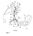
- Figure 5 shows a portion of a passenger compartment 600 of a typical automotive vehicle 602.
- the front and rear doors and windows 604, 606 are shown diagrammatically with a B- pillar 610 located between them.
- Figure 5 also shows the components of a typical prior art three-point seat belt system 500.
- the three-point seat belt system 500 includes a seat belt retractor 501 and a length of seat belt webbing 502.
- a tongue 504 slides on the seat belt webbing and divides the seat belt webbing into a shoulder belt portion 506 and a lap belt portion 508.
- the lap belt portion 508 of the seat belt webbing is secured by an anchor 510 to the vehicle floor or another structural component of the vehicle.
- the shoulder belt portion of the seat belt webbing passes through a web guide 512, commonly called a D-ring, which typically has a support surface over which the shoulder belt slides.
- a web guide 512 commonly called a D-ring
- the terms web guide and D-ring are used interchangeably.
- US 5 601 311 may be referred to for an example of a typical web guide.
- the three-point seat belt system 500 includes a seat belt buckle 520 that is secured to the vehicle floor or seat frame 534.
- the height adjusting mechanism 550 usually includes a rail or track 552 that is secured to the upper regions of the B-pillar by one or more fasteners.
- the height adjusting mechanism 550 further includes a carrier 554 that can slide on the track or rail 552.
- the rail, track and carrier can take many forms.
- the carrier 554 may include a threaded bore to receive a shoulder bolt 556 that is used to secure the D-ring 512 to the carrier.
- the track has been secured to the B-pillar by two threaded fasteners inserted in corresponding openings 551 in the track or rail.
- the lower portion of the track or rail can be formed as a hook that is received through an opening in the B-pillar, thereby securing the lower end of the track.
- the upper end of the track is secured by a single threaded fastener.
- the vehicle seat 530 has been moved rearward, see arrow 532, from a normal installed position and from the B-pillar 610 of the vehicle.
- the manufacturer of the seat belt system 500 will supply the system to the automotive assembly factory in three parts: the height adjusting mechanism 550; the buckle 520; and a subassembly 560 comprising the retractor, seat belt, tongue, D-ring, and anchors.
- the installation of the seat belt system into the vehicle is relatively straightforward.
- the track or rail 552 is moved in the direction of arrow 570 to the B-pillar 610 and secured by the required number of fasteners.
- the buckle 520 is secured by a fastener 522 to a mounting surface such as the vehicle floor or seat belt frame.
- the retractor 501 is secured by a bolt to a lower portion of the B-pillar.
- the web guide 512 also called a D-ring, is lifted, as indicated by arrow 572, toward the previously mounted carrier 554 and aligned with the carrier 554. With the D-ring in place, the installer obtains a shoulder bolt 556 and installs the shoulder bolt into the threaded bore.
- Figure 1 illustrates a three-point seat belt system 100 of the present invention that has many of the components used in the prior art.
- the height adjusting mechanism 102 and D-ring 104 are secured together during initial assembly and encompass part of a subassembly 106.
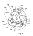
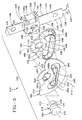
- Figures 2 and 3 illustrate in greater detail the connection of the D-ring 104 and the carrier 140 of height adjusting mechanism 102.
- the integration of the web guide with the height adjusting mechanism 102 prior to assembly in the vehicle provides a more efficient method of installing the three-point seat belt system in the vehicle.
- the assembler to laboriously and inefficiently secure the web guide to the carrier of the height adjusting mechanism on the vehicle assembly line.
- This step is accomplished during the manufacture of the subassembly 106, thereby saving time, lowering the cost of the vehicle, making the assembly process less taxing, less stressful and easier for the assembler, and increasing the efficiency of the installation process in the vehicle assembly facility.
- the installer obtains the height adjusting mechanism 102, moves it into the designated location on the B-pillar, with the designated location being shown by phantom lines 112, and proceeds to install the height adjusting mechanism in the manner known in the prior art.
- the lifting of the height adjusting mechanism 102 carries with it the web guide 104, as these parts, as mentioned, comprise a subassembly 106.
- the present invention eliminates a number of assembly steps found in the prior art.
- the present invention includes some assembly steps found in a prior art installation. For example the anchor 510 and buckle 520 are secured to the vehicle using known techniques.
- FIGS 2 and 3 illustrate in greater detail the major elements of the height adjusting mechanism 102, which now includes the web guide 104 as part of the subassembly 106.
- the height adjusting mechanism 102 includes a bar 120 having a generally oblong cross-section.
- the bar 120 includes a front face 122, rear face 124, and sides 126, 128.
- the bar 120 may include a plurality of discrete teeth 130 located along one side 128.
- the teeth 130 are optional as locking will occur with or without the teeth, although the teeth are preferred.
- the bar 120 includes at least one mounting opening 132 through which a threaded bolt passes to secure the bar to the B-pillar 610.
- Another mounting opening 134 can be fabricated within the lower portions of the bar.
- the bar 120 has a rearward bend 136 that forms a hook 147 in the lower portion of bar 120.
- the hook 147 is received in a vertically oriented opening in the B-pillar 610.
- the bar 120 is then rotated 90° to a vertical orientation and secured to the B-pillar.
- the carrier 140 is received in a sliding manner on the bar 120.
- the carrier 140 has four sides: a top 142, a bottom 144, a front face 146 and a side 148.
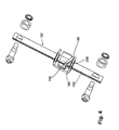
- a portion of the locking mechanism 250 shown in Figure 4 is received in a space 150 between the side 148 and the bottom 144.
- the top 142 and side 148 each have an oval opening 152 for receipt of the bar 120.
- An oval bushing (not shown) can be inserted within each respective opening 152 primarily to reduce vibration between the carrier 140 and the bar 120.
- the front face 146 includes a keyed opening 154 having a larger diameter portion 156 and a narrow diameter portion 158.
- the web guide 104 is secured to the carrier 140 by a rivet 160.
- the rivet 160 prevents the axial displacement of the D-ring and carrier while permitting the D-ring freedom to rotate through a limited range relative to the carrier 120.
- the D-ring 104 includes a weight bearing body 162, which includes an arcuate shaped seat belt supporting surface 164 formed in a U-shaped concave groove.
- the supporting surface may be smooth, include a number of grooves or projections which, depending on the mounting geometry of the web guide in the vehicle, might be needed to laterally stabilize the seat belt on surface 164.
- the web guide 104 is formed as a one-piece metal stamping and may be appropriately coated to reduce friction with the woven seat belt.
- the web guide body 162 includes an opening 170 for receipt of the rivet 160.
- This flat surface 165 facilitates rotation of the body 162 relative to the carrier.
- the seat belt supporting surface 164 is formed as a forwardly extending lip with a curved bottom and sides, which extend away from the surface 165 in a forward direction in Figure 3.
- the rivet 160 includes a head 172 and a shaft 174.
- the shaft 174 includes an upper portion 176 having a generally circular cross-section.
- the shaft 174 includes a rectangular lower section 178 positioned below the upper portion 176.
- the shaft 174 is sized to fit within opening 154 of carrier 140 in a sliding manner.
- a rear rivet head 175 shown in phantom line is formed at the rear of the shaft 174 after assembly, holding the rivet 160 to the carrier 140.
- the rear rivet head is located against an inner surface 146a of the face 146 of the carrier 140.
- the web guide 104 has an opening 170.
- the opening 170 has a first portion 180, which has a diameter slightly greater than the diameter of the upper portion 176 of the rivet 160.
- the first portion 180 of the web guide 104 rotates upon the upper portion 176 of the shaft of the rivet 160.
- the opening 170 includes a curved lower portion 182 having a diameter greater than the first portion 180.
- the lower portion 182 is configured as a sector of a larger diameter circle terminating in the shoulders or stops 184, 186.
- the rotation of the web guide 104 in the direction of arrow 190 is limited to approximately 42 degrees whereupon the shoulder 186 contacts one side of section 178 of rivet 160.
- the rotation of the ring 104 in the direction of arrow 192 is limited to -42 degrees by the engagement of the shoulder 184 with the opposing face of the rivet section 178.
- a lower portion 196, of the web guide body 162 extends downward towards a surface 164 and creates a narrow spacing 198 through which the shoulder belt 506, shown in phantom line, extends. This narrow spacing can also be obtained through the use of a trim part 200.
- a rivet 160 such as the shaft 174 and the projecting rivet section 178, which provide the functions of supporting the D-ring and providing the mechanism stop, have been transferred to the carrier 140.
- the shaft 174 is part of a rivet 160a inserted within a circular fastener opening 154 in the face 146 of the carrier and secured thereto.
- the D-ring body 162 rotates about the upper portions 176 of shaft 174.
- the D-ring, and trim part 200 discussed below, are secured to the carrier by a threaded bolt 160b inserted within a threaded bore 174a of the shaft 174.
- the web guide is installed relative to a trim panel, and it may be desirable to attach a trim part 200 to the structural portions of the web guide to cover openings in the trim panel, which is for example secured to the B-pillar.
- the trim part 200 has an opening 202.
- Tabs or pins 203a,b extend rearward of the trim part 200 and are secured to the web guide body 162. The tabs or pins permit the trim part to rotate with the web guide 104.
- the trim part 200 includes an opening 204 below the opening 202.
- a surface 206 of the opening 202 is received behind a lip or groove 210 formed in the web guide 104 behind a surface 164 as shown in Figures 2 and 3.
- the body 212 of the trim part 200 is wider than the web guide 104.
- the trim part 200 When viewed in the direction of arrow 214 the trim part 200 covers the intemal spaces and parts of the height adjusting mechanism and/or trim panel (not shown).
- the trim part 200 further includes a depending lobe 220, which creates a thin spacing 222, slightly greater than the thickness of the seat belt 506, through which the seat belt 506 slides. This lobe can also be formed in the web guide.
- a large trim part (not shown) known as a B-pillar trim is fitted to the B-pillar 610.
- the B-pillar trim receives the web guide 104 and a manual activation mechanism, which is used to release the lock mechanism of the height adjusting mechanism thereby permitting the web guide and carrier to be repositioned along the rail 120.
Landscapes
- Engineering & Computer Science (AREA)
- Mechanical Engineering (AREA)
- Automotive Seat Belt Assembly (AREA)
- Emergency Lowering Means (AREA)
Abstract
Description
- The present invention relates to a height adjusting mechanism for a web guide of a seat belt system.
- Figure 5 shows a portion of a
passenger compartment 600 of a typical automotive vehicle 602. The front and rear doors andwindows pillar 610 located between them. Figure 5 also shows the components of a typical prior art three-pointseat belt system 500. The three-pointseat belt system 500 includes aseat belt retractor 501 and a length ofseat belt webbing 502. Atongue 504 slides on the seat belt webbing and divides the seat belt webbing into ashoulder belt portion 506 and alap belt portion 508. Thelap belt portion 508 of the seat belt webbing is secured by ananchor 510 to the vehicle floor or another structural component of the vehicle. The shoulder belt portion of the seat belt webbing passes through aweb guide 512, commonly called a D-ring, which typically has a support surface over which the shoulder belt slides. The terms web guide and D-ring are used interchangeably.US 5 601 311 may be referred to for an example of a typical web guide. - It is an accepted practice to mount the web guide on a vertically adjustable mechanism, which is typically called a
height adjuster 550.US 5 050 907 andUS 5 230 534 disclose adjusting mechanisms. The three-pointseat belt system 500 includes aseat belt buckle 520 that is secured to the vehicle floor orseat frame 534. Theheight adjusting mechanism 550 usually includes a rail ortrack 552 that is secured to the upper regions of the B-pillar by one or more fasteners. Theheight adjusting mechanism 550 further includes acarrier 554 that can slide on the track orrail 552. The rail, track and carrier can take many forms. Thecarrier 554 may include a threaded bore to receive ashoulder bolt 556 that is used to secure the D-ring 512 to the carrier. Historically the track has been secured to the B-pillar by two threaded fasteners inserted incorresponding openings 551 in the track or rail. Alternatively, the lower portion of the track or rail can be formed as a hook that is received through an opening in the B-pillar, thereby securing the lower end of the track. In this design the upper end of the track is secured by a single threaded fastener. In Figure 5, for the purpose of illustration, thevehicle seat 530 has been moved rearward, seearrow 532, from a normal installed position and from the B-pillar 610 of the vehicle. - The manufacturer of the
seat belt system 500 will supply the system to the automotive assembly factory in three parts: theheight adjusting mechanism 550; thebuckle 520; and asubassembly 560 comprising the retractor, seat belt, tongue, D-ring, and anchors. - The installation of the seat belt system into the vehicle is relatively straightforward. The track or
rail 552 is moved in the direction ofarrow 570 to the B-pillar 610 and secured by the required number of fasteners. Thebuckle 520 is secured by afastener 522 to a mounting surface such as the vehicle floor or seat belt frame. Subsequently, theretractor 501 is secured by a bolt to a lower portion of the B-pillar. Thereafter, theweb guide 512, also called a D-ring, is lifted, as indicated byarrow 572, toward the previously mountedcarrier 554 and aligned with thecarrier 554. With the D-ring in place, the installer obtains ashoulder bolt 556 and installs the shoulder bolt into the threaded bore. - In a manufacturing environment in which the vehicle may be moving down the assembly line, it is difficult to hold the D-ring in place and maintain the alignment of the D-ring to the carrier and then insert the
shoulder bolt 556 while holding the D-ring in place. The shoulder bolt may be dropped or misplaced, adding valuable time and cost to the assembly process. The assembler must hold the D-ring in one hand, insert and thread the shoulder bolt with another hand and then, once the shoulder bolt is partially threaded to the carrier, locate, lift and use a power screwdriver to complete the installation. Each of the installation steps takes time, and under certain situations some of these installation steps have to be repeated, as these steps may not have been done praperly. - These problems are overcome by the present invention which provides in claim 1 an improved height adjusting mechanism assembly for a seat belt as well as an improved method of assembly.
- Figure 1 shows a passenger compartment of a vehicle and a seat belt system of the present invention.
- Figure 2 shows a web guide fixed to a carrier of a height adjusting mechanism.
- Figure 3 is an exploded view of the assembly of Figure 2.
- Figure 3a is an exploded view of an alternate embodiment of the present invention.
- Figure 4 shows a lock mechanism.
- Figure 5 shows a prior art three-point seat belt system.
- Figure 1 illustrates a three-point
seat belt system 100 of the present invention that has many of the components used in the prior art. Theheight adjusting mechanism 102 and D-ring 104 are secured together during initial assembly and encompass part of asubassembly 106. Figures 2 and 3 illustrate in greater detail the connection of the D-ring 104 and thecarrier 140 ofheight adjusting mechanism 102. - The integration of the web guide with the
height adjusting mechanism 102 prior to assembly in the vehicle provides a more efficient method of installing the three-point seat belt system in the vehicle. In the present invention there is no need for the assembler to laboriously and inefficiently secure the web guide to the carrier of the height adjusting mechanism on the vehicle assembly line. This step is accomplished during the manufacture of thesubassembly 106, thereby saving time, lowering the cost of the vehicle, making the assembly process less taxing, less stressful and easier for the assembler, and increasing the efficiency of the installation process in the vehicle assembly facility. In the vehicle assembly facility, after securing theseat belt retractor 501 to the B-pillar 610, the installer obtains theheight adjusting mechanism 102, moves it into the designated location on the B-pillar, with the designated location being shown byphantom lines 112, and proceeds to install the height adjusting mechanism in the manner known in the prior art. The lifting of theheight adjusting mechanism 102 carries with it theweb guide 104, as these parts, as mentioned, comprise asubassembly 106. - The present invention eliminates a number of assembly steps found in the prior art. The present invention includes some assembly steps found in a prior art installation. For example the
anchor 510 andbuckle 520 are secured to the vehicle using known techniques. - Figures 2 and 3 illustrate in greater detail the major elements of the
height adjusting mechanism 102, which now includes theweb guide 104 as part of thesubassembly 106. Theheight adjusting mechanism 102 includes abar 120 having a generally oblong cross-section. Thebar 120 includes afront face 122,rear face 124, andsides bar 120 may include a plurality ofdiscrete teeth 130 located along oneside 128. Theteeth 130 are optional as locking will occur with or without the teeth, although the teeth are preferred. Thebar 120 includes at least one mounting opening 132 through which a threaded bolt passes to secure the bar to the B-pillar 610. Another mounting opening 134 can be fabricated within the lower portions of the bar. An additional mounting fastener would be used in conjunction with the additional mounting opening 134. As illustrated, thebar 120 has arearward bend 136 that forms ahook 147 in the lower portion ofbar 120. Thehook 147 is received in a vertically oriented opening in the B-pillar 610. Thebar 120 is then rotated 90° to a vertical orientation and secured to the B-pillar. - The
carrier 140 is received in a sliding manner on thebar 120. Thecarrier 140 has four sides: atop 142, abottom 144, afront face 146 and aside 148. A portion of thelocking mechanism 250 shown in Figure 4 is received in aspace 150 between theside 148 and thebottom 144. Thetop 142 andside 148 each have anoval opening 152 for receipt of thebar 120. An oval bushing (not shown) can be inserted within eachrespective opening 152 primarily to reduce vibration between thecarrier 140 and thebar 120. Thefront face 146 includes akeyed opening 154 having alarger diameter portion 156 and anarrow diameter portion 158. - The
web guide 104 is secured to thecarrier 140 by arivet 160. Therivet 160 prevents the axial displacement of the D-ring and carrier while permitting the D-ring freedom to rotate through a limited range relative to thecarrier 120. The D-ring 104 includes aweight bearing body 162, which includes an arcuate shaped seatbelt supporting surface 164 formed in a U-shaped concave groove. The supporting surface may be smooth, include a number of grooves or projections which, depending on the mounting geometry of the web guide in the vehicle, might be needed to laterally stabilize the seat belt onsurface 164. As illustrated, theweb guide 104 is formed as a one-piece metal stamping and may be appropriately coated to reduce friction with the woven seat belt. Theweb guide body 162 includes anopening 170 for receipt of therivet 160. That portion of thebody 162 facing thefront face 146 of the carrier generally about theopening 170, as well as the rear of the opposing two dependingsides 163, has a generallyflat surface 165. Thisflat surface 165 facilitates rotation of thebody 162 relative to the carrier. The seatbelt supporting surface 164 is formed as a forwardly extending lip with a curved bottom and sides, which extend away from thesurface 165 in a forward direction in Figure 3. - The
rivet 160 includes ahead 172 and ashaft 174. Theshaft 174 includes anupper portion 176 having a generally circular cross-section. Theshaft 174 includes a rectangularlower section 178 positioned below theupper portion 176. Theshaft 174 is sized to fit within opening 154 ofcarrier 140 in a sliding manner. After therivet 160 is located in thecarrier 140, arear rivet head 175 shown in phantom line is formed at the rear of theshaft 174 after assembly, holding therivet 160 to thecarrier 140. The rear rivet head is located against aninner surface 146a of theface 146 of thecarrier 140. - In Figures 2 and 3 the
web guide 104 has anopening 170. Theopening 170 has afirst portion 180, which has a diameter slightly greater than the diameter of theupper portion 176 of therivet 160. Thefirst portion 180 of theweb guide 104 rotates upon theupper portion 176 of the shaft of therivet 160. Theopening 170 includes a curvedlower portion 182 having a diameter greater than thefirst portion 180. Thelower portion 182 is configured as a sector of a larger diameter circle terminating in the shoulders or stops 184, 186. The rotation of theweb guide 104 in the direction ofarrow 190 is limited to approximately 42 degrees whereupon theshoulder 186 contacts one side ofsection 178 ofrivet 160. Similarly, the rotation of thering 104 in the direction ofarrow 192 is limited to -42 degrees by the engagement of theshoulder 184 with the opposing face of therivet section 178. - A
lower portion 196, of theweb guide body 162, extends downward towards asurface 164 and creates anarrow spacing 198 through which theshoulder belt 506, shown in phantom line, extends. This narrow spacing can also be obtained through the use of atrim part 200. - Reference is briefly made to the alternate embodiment of Figure 3a. Those features of a
rivet 160 such as theshaft 174 and the projectingrivet section 178, which provide the functions of supporting the D-ring and providing the mechanism stop, have been transferred to thecarrier 140. In this embodiment theshaft 174 is part of arivet 160a inserted within acircular fastener opening 154 in theface 146 of the carrier and secured thereto. The D-ring body 162 rotates about theupper portions 176 ofshaft 174. The D-ring, andtrim part 200 discussed below, are secured to the carrier by a threadedbolt 160b inserted within a threadedbore 174a of theshaft 174. - In certain situations the web guide is installed relative to a trim panel, and it may be desirable to attach a
trim part 200 to the structural portions of the web guide to cover openings in the trim panel, which is for example secured to the B-pillar. Thetrim part 200 has anopening 202. Tabs orpins 203a,b extend rearward of thetrim part 200 and are secured to theweb guide body 162. The tabs or pins permit the trim part to rotate with theweb guide 104. Thetrim part 200 includes anopening 204 below theopening 202. Asurface 206 of theopening 202 is received behind a lip or groove 210 formed in theweb guide 104 behind asurface 164 as shown in Figures 2 and 3. In Figures 2 and 3 thebody 212 of thetrim part 200 is wider than theweb guide 104. When viewed in the direction ofarrow 214 thetrim part 200 covers the intemal spaces and parts of the height adjusting mechanism and/or trim panel (not shown). Thetrim part 200 further includes a dependinglobe 220, which creates athin spacing 222, slightly greater than the thickness of theseat belt 506, through which theseat belt 506 slides. This lobe can also be formed in the web guide. - As known in the industry, a large trim part (not shown) known as a B-pillar trim is fitted to the B-
pillar 610. The B-pillar trim receives theweb guide 104 and a manual activation mechanism, which is used to release the lock mechanism of the height adjusting mechanism thereby permitting the web guide and carrier to be repositioned along therail 120.
Claims (7)
- A seat belt system (100) comprising a seat belt retractor (501), a height adjusting mechanism (102) and a web guide (104), characterized by the height adjusting mechanism (102) and web guide (104) being part of a subassembly (106) configured to be mounted together to a mounting surface.
- A seat belt system (100) according to Claim 1 wherein the height adjusting mechanism (102) has a bar or track (120) and a carrier (140), the web guide (104) being secured to the carrier (140) to form the subassembly (106).
- A seat belt system (100) according to Claim 1 or 2 including a generally planar front surface (146) and wherein the web guide (104) includes a body (162) having a keyed mounting opening (170), the mounting opening (170) including opposing shoulder or first stops (184, 186) for limiting the rotation of the web guide (104), the front face (146) of the carrier (140) including a fastener opening (154), the system including a fastener (160, 160a) mountable to the fastener opening (154) in the carrier (140), the web guide (104) being rotatable upon a portion of the fastener (160, 160a), the fastener (160, 160a) including a mechanism stop that interferes with the first stops (184, 186) to limit the rotation of the web guide (104).
- A seat belt system (100) according to Claim 3 wherein the fastener opening (154) in the front face (146) of the carrier (140) is either circular or keyed and wherein the fastener is either a rivet (160) secured to the carrier (140) or a combination of a rivet (160a) secured to the carrier (140) and a bolt (160b) inserted within a bore (174a) of a shaft (174).
- A seat belt system (100) according to any of Claims 1-4 wherein the web guide (104) includes a body (162) having a central body portion and depending sides the central body portion and depending sides configured as a head and shoulders, the central body portion and depending sides generally adjacent the mounting opening, the web guide (104) including a flat surface (165) facing the front face of the carrier (140), the web guide (104) further including an arcuate lip extending away from the front face of the carrier (140) and away from the flat surface of the web guide (104), the arcuate lip forming a surface (164) for supporting a seat belt in a sliding manner.
- A seat belt system (100) according to any of Claims 1 - 5 installed into a passenger compartment of a vehicle by a method including the steps of:a. securing the web guide (104) to the carrier (140) so the height adjusting mechanism (102) and web guide (104) form a subassembly (106);b. locating and securing the seat belt retractor (501) to a designated location within the vehicle; andc. lifting the subassembly (106) and manipulating the height adjusting mechanism (102) to a designated location in the vehicle and securing the height adjusting mechanism (102) to the designated location, where the step of lifting the subassembly (106) simultaneously locates the web guide (104) to a designated location.
- A seat belt system (100) according to any of Claims 1 - 5 installed into a passenger compartment of a vehicle by the method as defined in Claim 6 wherein the step of securing the web guide (104) to the carrier (140) includes riveting the web guide (104) to the carrier (140).
Applications Claiming Priority (1)
| Application Number | Priority Date | Filing Date | Title |
|---|---|---|---|
| US70556205P | 2005-08-04 | 2005-08-04 |
Publications (2)
| Publication Number | Publication Date |
|---|---|
| EP1749713A1 true EP1749713A1 (en) | 2007-02-07 |
| EP1749713B1 EP1749713B1 (en) | 2008-03-26 |
Family
ID=36992553
Family Applications (1)
| Application Number | Title | Priority Date | Filing Date |
|---|---|---|---|
| EP06015537A Not-in-force EP1749713B1 (en) | 2005-08-04 | 2006-07-26 | Seat belt assembly and method of installation |
Country Status (4)
| Country | Link |
|---|---|
| US (1) | US7367590B2 (en) |
| EP (1) | EP1749713B1 (en) |
| AT (1) | ATE390330T1 (en) |
| DE (1) | DE602006000806T2 (en) |
Cited By (2)
| Publication number | Priority date | Publication date | Assignee | Title |
|---|---|---|---|---|
| FR2930499A1 (en) * | 2008-04-29 | 2009-10-30 | Peugeot Citroen Automobiles Sa | Return device for seat belt strap of drophead, has strap guiding element screwed on support element by fixation screw, where support element is integrated to structure of vehicle and formed by threaded spacer |
| CN108068748A (en) * | 2016-11-17 | 2018-05-25 | 福特全球技术公司 | For the bracket of sliding equipment |
Families Citing this family (33)
| Publication number | Priority date | Publication date | Assignee | Title |
|---|---|---|---|---|
| JP3845425B2 (en) * | 2004-05-12 | 2006-11-15 | 本田技研工業株式会社 | Adjustment structure of seat belt device in vehicle |
| US7263750B2 (en) | 2005-06-09 | 2007-09-04 | Amsafe, Inc. | Buckle assembly having single release for multiple belt connectors |
| JP2007050824A (en) * | 2005-08-19 | 2007-03-01 | Takata Corp | Guide anchor for seat belt and seat belt device provided therewith |
| US7806439B2 (en) * | 2007-05-16 | 2010-10-05 | Autoliv Asp, Inc. | Active anti-bunching D-ring seat belt system |
| US7980590B2 (en) | 2008-03-19 | 2011-07-19 | Amsafe, Inc. | Inflatable personal restraint systems having web-mounted inflators and associated methods of use and manufacture |
| US7665761B1 (en) | 2008-03-27 | 2010-02-23 | Amsafe, Inc. | Inflatable personal restraint systems and associated methods of use and manufacture |
| WO2010037103A1 (en) | 2008-09-29 | 2010-04-01 | Amsafe, Inc. | Tensioning apparatuses for occupant restraint systems and associated systems and methods |
| US8469401B2 (en) | 2009-02-23 | 2013-06-25 | Amsafe, Inc. | Seat harness pretensioner |
| US8403612B2 (en) * | 2009-07-29 | 2013-03-26 | Toyota Motor Engineering & Manufacturing North America, Inc. | Fastener assembly |
| US8393645B2 (en) | 2009-11-02 | 2013-03-12 | Amsafe Commercial Products, Inc. | Devices for adjusting tension in seat belts and other restraint system webs, and associated methods |
| US8683666B2 (en) | 2009-11-04 | 2014-04-01 | Amsafe Commercial Products, Inc. | Restraint system buckle components having tactile surfaces, and associated methods of use and manufacture |
| US8940122B2 (en) * | 2010-03-12 | 2015-01-27 | Wrapsol Acquisition, Llc | Protective adhesive film, method of adhering protective adhesive film to a device, and device comprising protective adhesive film |
| US8627554B1 (en) | 2010-05-03 | 2014-01-14 | Amsafe, Inc. (Phoenix Group) | Buckle assemblies with swivel and dual release features and associated methods of use and manufacture |
| US8777323B2 (en) | 2010-07-20 | 2014-07-15 | Amsafe, Inc. | Restraint harnesses and associated methods of use and manufacture |
| USD655223S1 (en) | 2010-09-15 | 2012-03-06 | Amsafe Commercial Products, Inc. | Buckle assembly |
| USD661619S1 (en) | 2010-09-15 | 2012-06-12 | Amsafe Commercial Products, Inc. | Buckle assembly |
| US8469397B2 (en) | 2011-04-13 | 2013-06-25 | Amsafe, Inc. | Stitch patterns for restraint-mounted airbags and associated systems and methods |
| US8439398B2 (en) | 2011-07-29 | 2013-05-14 | Amsafe, Inc. | Inflator connectors for inflatable personal restraints and associated systems and methods |
| US8523220B1 (en) | 2012-03-19 | 2013-09-03 | Amsafe, Inc. | Structure mounted airbag assemblies and associated systems and methods |
| US9511866B2 (en) | 2012-03-19 | 2016-12-06 | Amsafe, Inc. | Structure mounted airbag assemblies and associated systems and methods |
| US9022483B2 (en) | 2012-06-07 | 2015-05-05 | Shield Restraint Systems, Inc. | Seatbelt buckle tongue assembly |
| EP2958453A4 (en) | 2013-02-19 | 2016-07-27 | Amsafe Inc | Buckle assemblies with lift latches and associated methods and systems |
| US9277788B2 (en) | 2013-02-19 | 2016-03-08 | Amsafe, Inc. | Dual release buckle assemblies and associated systems and methods |
| KR20140131824A (en) * | 2013-05-06 | 2014-11-14 | 아우토리브 디벨롭먼트 아베 | belt bag d-ring assembly f0r vehicles |
| US9352839B2 (en) | 2014-10-02 | 2016-05-31 | Amsafe, Inc. | Active positioning airbag assembly and associated systems and methods |
| WO2016100566A1 (en) | 2014-12-16 | 2016-06-23 | Shield Restraint Systems, Inc. | Web adjusters for use with restraint systems and associated methods of use and manufacture |
| JP6576634B2 (en) * | 2014-12-26 | 2019-09-18 | Joyson Safety Systems Japan株式会社 | Guide anchor and seat belt device |
| US9944245B2 (en) | 2015-03-28 | 2018-04-17 | Amsafe, Inc. | Extending pass-through airbag occupant restraint systems, and associated systems and methods |
| US9925950B2 (en) | 2015-04-11 | 2018-03-27 | Amsafe, Inc. | Active airbag vent system |
| US10604259B2 (en) | 2016-01-20 | 2020-03-31 | Amsafe, Inc. | Occupant restraint systems having extending restraints, and associated systems and methods |
| US9814282B2 (en) | 2016-02-02 | 2017-11-14 | Shield Restraint Systems, Inc. | Harsh environment buckle assemblies and associated systems and methods |
| US10611334B2 (en) | 2017-02-07 | 2020-04-07 | Shield Restraint Systems, Inc. | Web adjuster |
| US11014528B2 (en) * | 2019-04-19 | 2021-05-25 | Toyota Motor Engineering & Manufacturing North America, Inc. | Energy absorption for D-ring attachment bracket |
Citations (9)
| Publication number | Priority date | Publication date | Assignee | Title |
|---|---|---|---|---|
| US4682790A (en) * | 1985-03-29 | 1987-07-28 | Kabushiki Kaisha Tokai-Rika-Denki-Seisakusho | Webbing retaining structure |
| US4871192A (en) * | 1987-10-07 | 1989-10-03 | Ecia-Equipements Et Composants Pour L'industrie Automobile | Retention mechanism for a safety-belt band of manually adjustable position |
| US4982981A (en) * | 1988-11-04 | 1991-01-08 | Ecia-Equipements Et Composants Pour L'industrie Automobile | Mechanism for seat belt with a manually adjustable position |
| US5050907A (en) | 1990-06-29 | 1991-09-24 | Allied-Signal Inc. | Adjustable seat belt anchorage |
| US5230534A (en) | 1992-04-30 | 1993-07-27 | Allied-Signal Inc. | Adjustable seat belt turning loop anchorage with release button |
| EP0639485A1 (en) * | 1993-08-18 | 1995-02-22 | Adam Opel Ag | Fastening of a safety belt and its corresponding components |
| US5601311A (en) | 1994-02-17 | 1997-02-11 | Alliedsignal Inc. | Seat belt web guide |
| US5769456A (en) * | 1993-12-02 | 1998-06-23 | Autoliv Development Ab | Pre-fitted carrier unit for the functional parts of a safety belt system |
| US20020011749A1 (en) * | 2000-06-28 | 2002-01-31 | Norbert Janz | Rerouting device for a seat belt |
Family Cites Families (8)
| Publication number | Priority date | Publication date | Assignee | Title |
|---|---|---|---|---|
| JPS5822359U (en) * | 1981-08-07 | 1983-02-12 | 日本精工株式会社 | Adjustable seat belt anchor device |
| JPS5947558U (en) * | 1982-09-24 | 1984-03-29 | 日本精工株式会社 | Anchor mounting device |
| JPS6353848U (en) * | 1986-11-26 | 1988-04-11 | ||
| US5732974A (en) * | 1997-03-03 | 1998-03-31 | Trw Vehicle Safety Systems Inc. | Seat belt system energy management device replacement indicator |
| SE521991C2 (en) * | 1999-10-12 | 2003-12-23 | Volvo Lastvagnar Ab | Device and method for height adjustment of a seat belt's upper attachment point |
| JP2003011777A (en) * | 2001-06-28 | 2003-01-15 | Tokai Rika Co Ltd | Through anchor |
| JP3907658B2 (en) * | 2002-05-13 | 2007-04-18 | キー セーフティー システムズ、 インコーポレイテッド | Seat belt height adjuster |
| US7461866B2 (en) * | 2005-07-18 | 2008-12-09 | Key Safety Systems, Inc. | Height adjuster with return spring |
-
2006
- 2006-07-12 US US11/457,072 patent/US7367590B2/en not_active Expired - Fee Related
- 2006-07-26 AT AT06015537T patent/ATE390330T1/en not_active IP Right Cessation
- 2006-07-26 EP EP06015537A patent/EP1749713B1/en not_active Not-in-force
- 2006-07-26 DE DE602006000806T patent/DE602006000806T2/en active Active
Patent Citations (9)
| Publication number | Priority date | Publication date | Assignee | Title |
|---|---|---|---|---|
| US4682790A (en) * | 1985-03-29 | 1987-07-28 | Kabushiki Kaisha Tokai-Rika-Denki-Seisakusho | Webbing retaining structure |
| US4871192A (en) * | 1987-10-07 | 1989-10-03 | Ecia-Equipements Et Composants Pour L'industrie Automobile | Retention mechanism for a safety-belt band of manually adjustable position |
| US4982981A (en) * | 1988-11-04 | 1991-01-08 | Ecia-Equipements Et Composants Pour L'industrie Automobile | Mechanism for seat belt with a manually adjustable position |
| US5050907A (en) | 1990-06-29 | 1991-09-24 | Allied-Signal Inc. | Adjustable seat belt anchorage |
| US5230534A (en) | 1992-04-30 | 1993-07-27 | Allied-Signal Inc. | Adjustable seat belt turning loop anchorage with release button |
| EP0639485A1 (en) * | 1993-08-18 | 1995-02-22 | Adam Opel Ag | Fastening of a safety belt and its corresponding components |
| US5769456A (en) * | 1993-12-02 | 1998-06-23 | Autoliv Development Ab | Pre-fitted carrier unit for the functional parts of a safety belt system |
| US5601311A (en) | 1994-02-17 | 1997-02-11 | Alliedsignal Inc. | Seat belt web guide |
| US20020011749A1 (en) * | 2000-06-28 | 2002-01-31 | Norbert Janz | Rerouting device for a seat belt |
Cited By (3)
| Publication number | Priority date | Publication date | Assignee | Title |
|---|---|---|---|---|
| FR2930499A1 (en) * | 2008-04-29 | 2009-10-30 | Peugeot Citroen Automobiles Sa | Return device for seat belt strap of drophead, has strap guiding element screwed on support element by fixation screw, where support element is integrated to structure of vehicle and formed by threaded spacer |
| CN108068748A (en) * | 2016-11-17 | 2018-05-25 | 福特全球技术公司 | For the bracket of sliding equipment |
| CN108068748B (en) * | 2016-11-17 | 2022-09-02 | 福特全球技术公司 | Bracket for sliding mechanism |
Also Published As
| Publication number | Publication date |
|---|---|
| US20070029773A1 (en) | 2007-02-08 |
| DE602006000806T2 (en) | 2009-04-30 |
| DE602006000806D1 (en) | 2008-05-08 |
| ATE390330T1 (en) | 2008-04-15 |
| EP1749713B1 (en) | 2008-03-26 |
| US7367590B2 (en) | 2008-05-06 |
Similar Documents
| Publication | Publication Date | Title |
|---|---|---|
| EP1749713A1 (en) | Seat belt assembly and method of installation | |
| US8807598B2 (en) | Guide loops for a seat belt system | |
| EP1442923A2 (en) | Seat track assembly and method of manufacture | |
| US7320157B2 (en) | Resilient clip fastener | |
| US7584998B2 (en) | Interlocking anchorage and method of installing a seat belt assembly | |
| CN111670133B (en) | Locking device and vehicle seat | |
| US20190232833A1 (en) | Longitudinal adjuster and vehicle seat | |
| US20110169295A1 (en) | Adjustable mounting system for vehicular body components | |
| US4720147A (en) | Adjustable vehicle seat belt anchor | |
| US6932378B2 (en) | Passenger air bag module with cover coupling mechanism | |
| US9694715B1 (en) | Removable vehicle seat assembly having angled striker surface | |
| JP4477505B2 (en) | Seat belt retractor housing fixing device | |
| US20100005623A1 (en) | Connector device on a retainer device for a cover of an openable vehicle roof | |
| US6722739B2 (en) | Fitting for a vehicle seat | |
| US20010046426A1 (en) | Resilient clip fastener | |
| US8967519B2 (en) | Safety belt retractor with variable load transfer in different function settings | |
| CA2504464C (en) | Seat assembly with tunable tie bar | |
| EP2181885A1 (en) | Latch device for removable connection of a seat structure to a motor-vehicle structure | |
| CN102958761B (en) | For the quick acting closure being fixed on the end of automobile of automobile safety seat belt | |
| US5603527A (en) | Shoulder belt mounting assembly | |
| JP2005001436A (en) | Seat belt guide structure | |
| EP2821294B1 (en) | Improvements in or relating to seat belt assemblies | |
| US11110888B2 (en) | Belt buckle assembly having a belt force limiter and method for installing the belt buckle assembly | |
| CN211731316U (en) | Mounting mechanism of safety limiting device and vehicle using same | |
| US20070169415A1 (en) | Window rail and bracket assembly |
Legal Events
| Date | Code | Title | Description |
|---|---|---|---|
| PUAI | Public reference made under article 153(3) epc to a published international application that has entered the european phase |
Free format text: ORIGINAL CODE: 0009012 |
|
| AK | Designated contracting states |
Kind code of ref document: A1 Designated state(s): AT BE BG CH CY CZ DE DK EE ES FI FR GB GR HU IE IS IT LI LT LU LV MC NL PL PT RO SE SI SK TR |
|
| AX | Request for extension of the european patent |
Extension state: AL BA HR MK YU |
|
| 17P | Request for examination filed |
Effective date: 20070427 |
|
| GRAP | Despatch of communication of intention to grant a patent |
Free format text: ORIGINAL CODE: EPIDOSNIGR1 |
|
| AKX | Designation fees paid |
Designated state(s): AT BE BG CH CY CZ DE DK EE ES FI FR GB GR HU IE IS IT LI LT LU LV MC NL PL PT RO SE SI SK TR |
|
| GRAS | Grant fee paid |
Free format text: ORIGINAL CODE: EPIDOSNIGR3 |
|
| GRAA | (expected) grant |
Free format text: ORIGINAL CODE: 0009210 |
|
| AK | Designated contracting states |
Kind code of ref document: B1 Designated state(s): AT BE BG CH CY CZ DE DK EE ES FI FR GB GR HU IE IS IT LI LT LU LV MC NL PL PT RO SE SI SK TR |
|
| REG | Reference to a national code |
Ref country code: GB Ref legal event code: FG4D |
|
| REG | Reference to a national code |
Ref country code: IE Ref legal event code: FG4D Ref country code: CH Ref legal event code: EP |
|
| REF | Corresponds to: |
Ref document number: 602006000806 Country of ref document: DE Date of ref document: 20080508 Kind code of ref document: P |
|
| PG25 | Lapsed in a contracting state [announced via postgrant information from national office to epo] |
Ref country code: FI Free format text: LAPSE BECAUSE OF FAILURE TO SUBMIT A TRANSLATION OF THE DESCRIPTION OR TO PAY THE FEE WITHIN THE PRESCRIBED TIME-LIMIT Effective date: 20080326 |
|
| PG25 | Lapsed in a contracting state [announced via postgrant information from national office to epo] |
Ref country code: AT Free format text: LAPSE BECAUSE OF FAILURE TO SUBMIT A TRANSLATION OF THE DESCRIPTION OR TO PAY THE FEE WITHIN THE PRESCRIBED TIME-LIMIT Effective date: 20080326 |
|
| NLV1 | Nl: lapsed or annulled due to failure to fulfill the requirements of art. 29p and 29m of the patents act | ||
| PG25 | Lapsed in a contracting state [announced via postgrant information from national office to epo] |
Ref country code: SI Free format text: LAPSE BECAUSE OF FAILURE TO SUBMIT A TRANSLATION OF THE DESCRIPTION OR TO PAY THE FEE WITHIN THE PRESCRIBED TIME-LIMIT Effective date: 20080326 Ref country code: BE Free format text: LAPSE BECAUSE OF FAILURE TO SUBMIT A TRANSLATION OF THE DESCRIPTION OR TO PAY THE FEE WITHIN THE PRESCRIBED TIME-LIMIT Effective date: 20080326 Ref country code: PL Free format text: LAPSE BECAUSE OF FAILURE TO SUBMIT A TRANSLATION OF THE DESCRIPTION OR TO PAY THE FEE WITHIN THE PRESCRIBED TIME-LIMIT Effective date: 20080326 Ref country code: LV Free format text: LAPSE BECAUSE OF FAILURE TO SUBMIT A TRANSLATION OF THE DESCRIPTION OR TO PAY THE FEE WITHIN THE PRESCRIBED TIME-LIMIT Effective date: 20080326 |
|
| ET | Fr: translation filed | ||
| PG25 | Lapsed in a contracting state [announced via postgrant information from national office to epo] |
Ref country code: CZ Free format text: LAPSE BECAUSE OF FAILURE TO SUBMIT A TRANSLATION OF THE DESCRIPTION OR TO PAY THE FEE WITHIN THE PRESCRIBED TIME-LIMIT Effective date: 20080326 Ref country code: ES Free format text: LAPSE BECAUSE OF FAILURE TO SUBMIT A TRANSLATION OF THE DESCRIPTION OR TO PAY THE FEE WITHIN THE PRESCRIBED TIME-LIMIT Effective date: 20080707 Ref country code: SE Free format text: LAPSE BECAUSE OF FAILURE TO SUBMIT A TRANSLATION OF THE DESCRIPTION OR TO PAY THE FEE WITHIN THE PRESCRIBED TIME-LIMIT Effective date: 20080626 Ref country code: PT Free format text: LAPSE BECAUSE OF FAILURE TO SUBMIT A TRANSLATION OF THE DESCRIPTION OR TO PAY THE FEE WITHIN THE PRESCRIBED TIME-LIMIT Effective date: 20080901 Ref country code: SK Free format text: LAPSE BECAUSE OF FAILURE TO SUBMIT A TRANSLATION OF THE DESCRIPTION OR TO PAY THE FEE WITHIN THE PRESCRIBED TIME-LIMIT Effective date: 20080326 |
|
| PG25 | Lapsed in a contracting state [announced via postgrant information from national office to epo] |
Ref country code: RO Free format text: LAPSE BECAUSE OF FAILURE TO SUBMIT A TRANSLATION OF THE DESCRIPTION OR TO PAY THE FEE WITHIN THE PRESCRIBED TIME-LIMIT Effective date: 20080326 Ref country code: NL Free format text: LAPSE BECAUSE OF FAILURE TO SUBMIT A TRANSLATION OF THE DESCRIPTION OR TO PAY THE FEE WITHIN THE PRESCRIBED TIME-LIMIT Effective date: 20080326 |
|
| PG25 | Lapsed in a contracting state [announced via postgrant information from national office to epo] |
Ref country code: IS Free format text: LAPSE BECAUSE OF FAILURE TO SUBMIT A TRANSLATION OF THE DESCRIPTION OR TO PAY THE FEE WITHIN THE PRESCRIBED TIME-LIMIT Effective date: 20080726 |
|
| PG25 | Lapsed in a contracting state [announced via postgrant information from national office to epo] |
Ref country code: LT Free format text: LAPSE BECAUSE OF FAILURE TO SUBMIT A TRANSLATION OF THE DESCRIPTION OR TO PAY THE FEE WITHIN THE PRESCRIBED TIME-LIMIT Effective date: 20080326 Ref country code: DK Free format text: LAPSE BECAUSE OF FAILURE TO SUBMIT A TRANSLATION OF THE DESCRIPTION OR TO PAY THE FEE WITHIN THE PRESCRIBED TIME-LIMIT Effective date: 20080326 |
|
| PLBE | No opposition filed within time limit |
Free format text: ORIGINAL CODE: 0009261 |
|
| STAA | Information on the status of an ep patent application or granted ep patent |
Free format text: STATUS: NO OPPOSITION FILED WITHIN TIME LIMIT |
|
| 26N | No opposition filed |
Effective date: 20081230 |
|
| PG25 | Lapsed in a contracting state [announced via postgrant information from national office to epo] |
Ref country code: MC Free format text: LAPSE BECAUSE OF NON-PAYMENT OF DUE FEES Effective date: 20080731 |
|
| PG25 | Lapsed in a contracting state [announced via postgrant information from national office to epo] |
Ref country code: EE Free format text: LAPSE BECAUSE OF FAILURE TO SUBMIT A TRANSLATION OF THE DESCRIPTION OR TO PAY THE FEE WITHIN THE PRESCRIBED TIME-LIMIT Effective date: 20080326 Ref country code: BG Free format text: LAPSE BECAUSE OF FAILURE TO SUBMIT A TRANSLATION OF THE DESCRIPTION OR TO PAY THE FEE WITHIN THE PRESCRIBED TIME-LIMIT Effective date: 20080626 |
|
| PG25 | Lapsed in a contracting state [announced via postgrant information from national office to epo] |
Ref country code: IE Free format text: LAPSE BECAUSE OF NON-PAYMENT OF DUE FEES Effective date: 20080728 |
|
| PG25 | Lapsed in a contracting state [announced via postgrant information from national office to epo] |
Ref country code: CY Free format text: LAPSE BECAUSE OF FAILURE TO SUBMIT A TRANSLATION OF THE DESCRIPTION OR TO PAY THE FEE WITHIN THE PRESCRIBED TIME-LIMIT Effective date: 20080326 |
|
| PG25 | Lapsed in a contracting state [announced via postgrant information from national office to epo] |
Ref country code: LU Free format text: LAPSE BECAUSE OF NON-PAYMENT OF DUE FEES Effective date: 20080726 Ref country code: HU Free format text: LAPSE BECAUSE OF FAILURE TO SUBMIT A TRANSLATION OF THE DESCRIPTION OR TO PAY THE FEE WITHIN THE PRESCRIBED TIME-LIMIT Effective date: 20080927 |
|
| PG25 | Lapsed in a contracting state [announced via postgrant information from national office to epo] |
Ref country code: TR Free format text: LAPSE BECAUSE OF FAILURE TO SUBMIT A TRANSLATION OF THE DESCRIPTION OR TO PAY THE FEE WITHIN THE PRESCRIBED TIME-LIMIT Effective date: 20080326 |
|
| PG25 | Lapsed in a contracting state [announced via postgrant information from national office to epo] |
Ref country code: GR Free format text: LAPSE BECAUSE OF FAILURE TO SUBMIT A TRANSLATION OF THE DESCRIPTION OR TO PAY THE FEE WITHIN THE PRESCRIBED TIME-LIMIT Effective date: 20080627 |
|
| PGFP | Annual fee paid to national office [announced via postgrant information from national office to epo] |
Ref country code: DE Payment date: 20100730 Year of fee payment: 5 Ref country code: FR Payment date: 20100813 Year of fee payment: 5 Ref country code: GB Payment date: 20100616 Year of fee payment: 5 Ref country code: IT Payment date: 20100722 Year of fee payment: 5 |
|
| REG | Reference to a national code |
Ref country code: CH Ref legal event code: PL |
|
| PG25 | Lapsed in a contracting state [announced via postgrant information from national office to epo] |
Ref country code: LI Free format text: LAPSE BECAUSE OF NON-PAYMENT OF DUE FEES Effective date: 20100731 Ref country code: CH Free format text: LAPSE BECAUSE OF NON-PAYMENT OF DUE FEES Effective date: 20100731 |
|
| GBPC | Gb: european patent ceased through non-payment of renewal fee |
Effective date: 20110726 |
|
| REG | Reference to a national code |
Ref country code: FR Ref legal event code: ST Effective date: 20120330 |
|
| PG25 | Lapsed in a contracting state [announced via postgrant information from national office to epo] |
Ref country code: DE Free format text: LAPSE BECAUSE OF NON-PAYMENT OF DUE FEES Effective date: 20120201 Ref country code: FR Free format text: LAPSE BECAUSE OF NON-PAYMENT OF DUE FEES Effective date: 20110801 |
|
| REG | Reference to a national code |
Ref country code: DE Ref legal event code: R119 Ref document number: 602006000806 Country of ref document: DE Effective date: 20120201 |
|
| PG25 | Lapsed in a contracting state [announced via postgrant information from national office to epo] |
Ref country code: IT Free format text: LAPSE BECAUSE OF NON-PAYMENT OF DUE FEES Effective date: 20110726 |
|
| PG25 | Lapsed in a contracting state [announced via postgrant information from national office to epo] |
Ref country code: GB Free format text: LAPSE BECAUSE OF NON-PAYMENT OF DUE FEES Effective date: 20110726 |