EP1749704A2 - Optical fiber sensor, manufacturing method thereof, and collision detection device - Google Patents
Optical fiber sensor, manufacturing method thereof, and collision detection device Download PDFInfo
- Publication number
- EP1749704A2 EP1749704A2 EP06011658A EP06011658A EP1749704A2 EP 1749704 A2 EP1749704 A2 EP 1749704A2 EP 06011658 A EP06011658 A EP 06011658A EP 06011658 A EP06011658 A EP 06011658A EP 1749704 A2 EP1749704 A2 EP 1749704A2
- Authority
- EP
- European Patent Office
- Prior art keywords
- optical fiber
- insertion hole
- molded member
- sensor
- detection
- Prior art date
- Legal status (The legal status is an assumption and is not a legal conclusion. Google has not performed a legal analysis and makes no representation as to the accuracy of the status listed.)
- Granted
Links
- 239000013307 optical fiber Substances 0.000 title claims abstract description 90
- 238000001514 detection method Methods 0.000 title claims abstract description 51
- 238000004519 manufacturing process Methods 0.000 title claims description 29
- 238000003780 insertion Methods 0.000 claims abstract description 101
- 230000037431 insertion Effects 0.000 claims abstract description 101
- 239000000835 fiber Substances 0.000 claims abstract description 52
- 239000004033 plastic Substances 0.000 claims abstract description 51
- 239000000945 filler Substances 0.000 claims abstract description 33
- 229920005989 resin Polymers 0.000 claims description 13
- 239000011347 resin Substances 0.000 claims description 13
- 239000000463 material Substances 0.000 claims description 12
- 229920001187 thermosetting polymer Polymers 0.000 claims description 12
- 230000000149 penetrating effect Effects 0.000 claims description 4
- 238000007664 blowing Methods 0.000 claims description 3
- 230000003247 decreasing effect Effects 0.000 abstract description 4
- 229920001971 elastomer Polymers 0.000 description 13
- 239000005060 rubber Substances 0.000 description 13
- 239000002184 metal Substances 0.000 description 12
- 230000001788 irregular Effects 0.000 description 9
- 239000004020 conductor Substances 0.000 description 5
- 238000000034 method Methods 0.000 description 5
- 239000006096 absorbing agent Substances 0.000 description 3
- 230000000694 effects Effects 0.000 description 3
- 238000012545 processing Methods 0.000 description 3
- 230000035945 sensitivity Effects 0.000 description 3
- 230000035939 shock Effects 0.000 description 3
- 238000012546 transfer Methods 0.000 description 3
- XUIMIQQOPSSXEZ-UHFFFAOYSA-N Silicon Chemical compound [Si] XUIMIQQOPSSXEZ-UHFFFAOYSA-N 0.000 description 2
- 208000027418 Wounds and injury Diseases 0.000 description 2
- 230000006835 compression Effects 0.000 description 2
- 238000007906 compression Methods 0.000 description 2
- 230000006378 damage Effects 0.000 description 2
- 208000014674 injury Diseases 0.000 description 2
- 239000012778 molding material Substances 0.000 description 2
- 229910052710 silicon Inorganic materials 0.000 description 2
- 239000010703 silicon Substances 0.000 description 2
- 230000008961 swelling Effects 0.000 description 2
- 238000007792 addition Methods 0.000 description 1
- 150000001875 compounds Chemical class 0.000 description 1
- 238000007796 conventional method Methods 0.000 description 1
- 238000005336 cracking Methods 0.000 description 1
- 230000006866 deterioration Effects 0.000 description 1
- 230000005484 gravity Effects 0.000 description 1
- 239000004519 grease Substances 0.000 description 1
- 238000010438 heat treatment Methods 0.000 description 1
- 239000007788 liquid Substances 0.000 description 1
- 239000003921 oil Substances 0.000 description 1
- 230000001151 other effect Effects 0.000 description 1
- 230000001902 propagating effect Effects 0.000 description 1
- 229920003051 synthetic elastomer Polymers 0.000 description 1
- 229920003002 synthetic resin Polymers 0.000 description 1
- 239000000057 synthetic resin Substances 0.000 description 1
- 239000005061 synthetic rubber Substances 0.000 description 1
- 238000004073 vulcanization Methods 0.000 description 1
Images


Classifications
-
- B—PERFORMING OPERATIONS; TRANSPORTING
- B60—VEHICLES IN GENERAL
- B60R—VEHICLES, VEHICLE FITTINGS, OR VEHICLE PARTS, NOT OTHERWISE PROVIDED FOR
- B60R21/00—Arrangements or fittings on vehicles for protecting or preventing injuries to occupants or pedestrians in case of accidents or other traffic risks
- B60R21/01—Electrical circuits for triggering passive safety arrangements, e.g. airbags, safety belt tighteners, in case of vehicle accidents or impending vehicle accidents
- B60R21/013—Electrical circuits for triggering passive safety arrangements, e.g. airbags, safety belt tighteners, in case of vehicle accidents or impending vehicle accidents including means for detecting collisions, impending collisions or roll-over
- B60R21/0136—Electrical circuits for triggering passive safety arrangements, e.g. airbags, safety belt tighteners, in case of vehicle accidents or impending vehicle accidents including means for detecting collisions, impending collisions or roll-over responsive to actual contact with an obstacle, e.g. to vehicle deformation, bumper displacement or bumper velocity relative to the vehicle
-
- G—PHYSICS
- G01—MEASURING; TESTING
- G01L—MEASURING FORCE, STRESS, TORQUE, WORK, MECHANICAL POWER, MECHANICAL EFFICIENCY, OR FLUID PRESSURE
- G01L1/00—Measuring force or stress, in general
- G01L1/24—Measuring force or stress, in general by measuring variations of optical properties of material when it is stressed, e.g. by photoelastic stress analysis using infrared, visible light, ultraviolet
- G01L1/242—Measuring force or stress, in general by measuring variations of optical properties of material when it is stressed, e.g. by photoelastic stress analysis using infrared, visible light, ultraviolet the material being an optical fibre
-
- B—PERFORMING OPERATIONS; TRANSPORTING
- B60—VEHICLES IN GENERAL
- B60R—VEHICLES, VEHICLE FITTINGS, OR VEHICLE PARTS, NOT OTHERWISE PROVIDED FOR
- B60R21/00—Arrangements or fittings on vehicles for protecting or preventing injuries to occupants or pedestrians in case of accidents or other traffic risks
- B60R21/01—Electrical circuits for triggering passive safety arrangements, e.g. airbags, safety belt tighteners, in case of vehicle accidents or impending vehicle accidents
- B60R2021/0104—Communication circuits for data transmission
- B60R2021/01081—Transmission medium
- B60R2021/01095—Transmission medium optical
Definitions
- the present invention relates to an optical fiber sensor in which a plastic fiber for detection is inserted in an insertion hole of a molded member, a manufacturing method thereof, and a collision detection device for a vehicle in which the optical fiber sensor is used as a collision detection sensor.
- FS sensor flexible pressure sensitive sensor
- an electric load sensor or, an impact detection sensor
- a conductor for detection is inserted in a hole of a rubber tube.
- a compressed air is sent to the hole of the rubber tube, the size of which is smaller than outside diameter of the conductor, and the rubber tube be swollen.
- the compressed air is evacuated after the conductor is inserted in the hole of the rubber tube under such a condition, the rubber tube shrinks and a gap between the rubber tube and the conductor disappears almost.
- the rubber tube swells evenly when the compressed air is sent to the hole of the rubber tube because wall thickness of the rubber tube is thick and uniform.
- wall thickness of the rubber tube is not uniform, a thin part swells intensively, and it is likely to rupture at the end.
- FS sensor is weak to electric noises and electromagnetic noises
- an optical fiber sensor has come to be used instead of FS sensor, which has the same function as FS sensor and is very strong to electric noises and electromagnetic noises.
- a stress-concentration plate with press punched holes is molded with a molded member, and a plastic fiber (POF) for detection is inserted in an insertion hole of the molded member.
- PPF plastic fiber
- the compressed air is sent to the insertion hole of the molded member, and the POF is inserted in the insertion hole in its state, as is the case with the manufacturing method of FS sensor.
- the thickness of molded member is different according to the press-punched hole of a stress concentration plate in the optical fiber sensor.
- the part where the wall thickness is especially thin swells when the compressed air is sent to the insertion hole. Therefore, a crack occurs in the molded member when the pressure of the compressed air is high, and in the worst case, the molded member breaks.
- an object of the present invention is to provide an optical fiber sensor and a manufacturing method thereof, in which insertion efficiency of a plastic fiber is improved, a risk that a molded member breaks down is decreased, and operation of the sensor in the low load and linearity of output of the sensor are improved.
- the present invention is made to achieve the above-mentioned object.
- the invention in one aspect resides in an optical fiber sensor in which a plastic fiber for detection may be inserted in an insertion hole of a molded member.
- filler may be filled in a gap between the plastic fiber for detection and the molded member.
- the filler may comprise thermosetting resin and/or gel material.
- the invention resides in an optical fiber sensor in which a plastic fiber for detection can be inserted in an insertion hole of a molded member. After blowing up said insertion hole by compressed air and/or inserting the plastic fiber for detection therein in its state, and the molded member may be contacted to the plastic fiber for detection in a direction where load can be applied by evacuating the compressed air.
- the section of the insertion hole can be oval.
- the section of the insertion hole can be oval, and/or a projecting slit can be formed along the overall length of a long direction of the insertion hole.
- the optical fiber sensor can be assembled to a fixed position, and said slit can be crushed by assembly pressure when the sensor is assembled.
- an optical fiber sensor in which a plastic fiber for detection can be inserted in an insertion hole of a molded member, when filler is filled from one end of the insertion hole to a gap between the molded member and the plastic fiber for detection after the plastic fiber for detection may be inserted in the insertion hole, the gap can be filled by sucking the filler from the other edge of the insertion hole.
- the filler can be filled in the gap by press fitting.
- the invention resides in a method of manufacturing an optical fiber sensor in which a plastic fiber for detection may be inserted in an insertion hole of a molded member.
- a gap between the molded member and the plastic fiber for detection can be filled by inserting the plastic fiber in the insertion hole after thermosetting resin may be applied on the plastic fiber for detection.
- thermosetting resin can be heated and harden after inserting the plastic fiber for detection on which the thermosetting resin may be applied in the insertion hole.
- the invention resides in a method of manufacturing an optical fiber sensor in which a plastic fiber for detection can be inserted in an insertion hole of a molded member. A gap between the molded member and the plastic fiber for detection can be filled by inserting the plastic fiber in the insertion hole after gel material may be applied on the plastic fiber for detection.
- the invention resides in a method of an optical fiber sensor in which a plastic fiber for detection can be inserted in an insertion hole of a molded member. After blowing up the insertion hole by compressed air and/or inserting the plastic fiber for detection therein in its state, the molded member can be contacted to the plastic fiber for detection in a direction where load may be applied by evacuating the compressed air.
- the invention resides in an optical fiber sensor for detecting the presence of the load applied to an optical fiber based on deformation of the optical fiber which may comprise an elongated molded member, an insertion hole penetrating the molded member in a long direction, and/or an optical fiber inserted in the insertion hole, wherein the inside diameter of the insertion hole can be larger than the outside diameter of the optical fiber, and/or a filler may be filled in a gap between the optical fiber and the molded member.
- the filler may contain thermosetting resin and/or gel material.
- the invention further may comprise an elongated stress-concentration plate for concentrating and/or applying stress to the optical fiber, arranged in contact with the optical fiber and in a long direction of the molded member and molded together with the molded member.
- the invention resides in a collision detection device which can be installed in a part of a vehicle, for detecting the collision of the vehicle based on deformation of the optical fiber which may comprise an elongated molded member, an insertion hole which may be penetrating the molded member in a long direction, an optical fiber which may be inserted in the insertion hole, a light emitting element which may be connected to one end of the optical fiber, which may supply a light signal to the optical fiber, a light receiving element which may be connected to the other end of the optical fiber, which may receive the light signal through the optical fiber, wherein inside diameter of the insertion hole can be larger than the outside diameter of the optical fiber, and/or a filler which may be filled in a gap between the optical fiber and the molded member.
- FIG. 1 is a cross-sectional view of an optical fiber sensor according to a first preferable embodiment of the present invention.
- FIG. 2 is a flow chart illustrating a manufacturing method of the optical fiber sensor shown in FIG. 1.
- FIG. 3 is a schematic view showing an example of characteristics of load to sensitivity when there is a gap between a molded member and a plastic fiber for detection and when there is not.
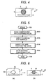
- FIG. 4 is a cross-sectional view of an optical fiber sensor according to a second embodiment of the present invention.
- FIG. 5 is a flow chart illustrating a manufacturing method of the optical fiber sensor shown in FIG. 3.
- FIG. 6(a) is a cross-sectional view of an optical fiber sensor according to a third embodiment of the present invention under manufacturing
- FIG. 6(b) is a cross-sectional view of a finished product.
- FIG. 7 is a perspective view of an irregular shaped metal rod used for a manufacturing method of the optical fiber sensor shown in FIG. 6(b).
- FIG. 8 is a flow chart illustrating of a manufacturing method of the optical fiber sensor shown in FIG. 6(b).
- FIG. 9 is a perspective view of an optical fiber sensor according to a fourth embodiment of the present invention.
- FIG. 10 is a cross-sectional view of a conventional optical fiber sensor.
- stress-concentration plate 102 with press punched holes is molded with molded member 103, and plastic fiber (POF) 105 for detection is inserted in insertion hole 104 of molded member 103.
- POF plastic fiber
- the compressed air is sent to insertion hole 104 of molded member 103, and POF 105 is inserted in the insertion hole 104 in its state, as is the case with the manufacturing method of FS sensor.
- molded member 103 is different according to the press-punched hole of stress concentration plate 102 in optical fiber sensor 101.
- the part where the wall thickness is especially thin swells when the compressed air is sent to insertion hole 104.
- a crack occurs in molded member 103 when the pressure of the compressed air is high, and in the worst case, the molded member breaks.
- FIG. 1 is a cross-sectional view showing an optical fiber sensor according to a first preferable embodiment of the present invention.
- stress concentration plate 2 which has the press punched hole is molded with molded member 3.
- Plastic fiber (POF) 5 for load (impact) detection is inserted in insertion hole 4 of molded member 3, and Filler (gap material) 6 is filled in the gap between molded member 3 and POF 5.
- Stress concentration plate 2 is formed like an elongated plate. Moreover, a plurality of press punched hole are formed at regular intervals along a long direction of stress concentration plate 2. Stress concentration plate 2 makes it easy for POF 5 to deform by concentrating and transferring the stress based on the load applied to sensor 1 through the press punched hole.
- the corrugated plate to which the corrugating process is applied may be used as stress concentration plate 2.
- Molded member 3 consists of synthetic resin or synthetic rubber. Insertion hole 4 is formed along a long direction (a direction perpendicular to the paper of FIG.
- thermosetting resin such as an RTV rubber, or one which consists of gel (jellylike or gel) materials such as silicon grease, silicon oil compounds can be used.
- the one which consists of the same material as molded member 3 is the best for filler 6.
- the rubber-like material is desirable for filler 6.
- an RTV rubber is in liquid form before vulcanization, and therefore, good only in heating (not need to press), it is preferable as filler 6.
- a method of manufacturing sensor 1 is explained with reference to FIG. 2.
- the method starts with stress concentration plate 2 molded with molded member 3, and insertion hole 4 formed to molded member 3 beforehand as shown in FIG. 2 (F21).
- the compressed air is sent to insertion hole 4 to expand it (F22).
- POF 5 is inserted therein and positioned (F23).
- the sending of the compressed air is ended (The compressed air is evacuated) (F24).
- filler 6 is filled from one end of insertion hole 4 to a gap between molded member 3 and POF 5 (F25), and the processing is ended (F26).
- Filler 6 can be easily filled in said gap by sucking air from the other end of insertion hole 4 and burying said gap when filler 6 is filled from one end of insertion hole 4 to said gap, and said gap can surely be filled. Further, said gap may be filled with filler 6 by press-fit. Sensor 1 of FIG. 1 is made as mentioned above.
- An amount of the bend loss or the compression loss is measured by observing the change (attenuation) in an amount of the transferred light propagating POF 5 by radiating light by a light emitting element from one end of POF 5 and receiving the light by a light receiving element at the other end thereof. The presence and the magnitude of the load applied to sensor 1 is detected from the measured loss amount.
- FIG. 3 shows characteristics of the load to the sensitivity in sensor 1 and sensor 101 of FIG. 10.
- the characteristic of sensor 1 (Without gap) is shown by a solid line and the characteristic of sensor 101 (With gap) is shown by a dotted line.
- the load effectively apply (transfer) to POF 5 even when the load applied to sensor 1 is low by filling filler 6 in the gap between molded member 3 and POF 5, and burying and losing the gap. Therefore, the sensitivity of sensor 1 is improved also in the low load area. Moreover, the linearity of the sensor output is also improved because the load is applied even in the low load area.
- Gap g exists between molded member 103 and POF 105 in conventional sensor 101. Therefore, the load is not transferred to POF 10 until the load to break the gap g applies sensor 101. As a result, sensor 101 does not work in the low load area, and the linearity of the sensor output is also bad.
- the efficiency (insertion characteristic) of the insertion of POF 5 to insertion hole 4 is improved because it is possible to enlarge insertion hole 4 more than the diameter (outside diameter) of POF 5. In this case, it does not need to swell molded member 3 by the compressed air.
- sensor 1 of FIG. 1 is made by filling filler 6 to the gap between molded member 3 and POF 5 after POF 5 is inserted in the insertion hole
- optical fiber sensor 41 of FIG. 4 is made by inserting POF 5 in insertion hole 4 after filler is applied on POF 5, and burying said gap.
- Other configuration of sensor 41 is the same as sensor 1.
- a method of manufacturing sensor 41 will be explained with reference to FIG. 5.
- stress concentration plate 2 has been molded with molded member 3 as shown in FIG. 4, and insertion hole 4 has been formed in molded member 3 beforehand.
- the compressed air is sent to insertion hole 4, and insertion hole 4 is expanded (F52). While applying filler 6 on the surface of POF 5 in the state, or after filler 6 is applied on the surface of POF 5 beforehand in another process (F53), this is inserted in insertion hole 4 and POF 5 is settled (F54). Then, sending the compressed air is ended (F55), said gap are filled and the processing is ended (F56).
- thermosetting resin is used as filler 6, the resin is harden by heat further.
- Sensor 41 of FIG. 4 is made by doing as mentioned above. Sensor 41 has the same effects as sensor 1 of FIG. 1.
- Optical fiber sensor 61 is made as shown in FIG. 6(b).
- the compressed air is sent to insertion hole 62, and insertion hole 62 is expanded as shown in FIG. 6(a).
- POF 5 is inserted in the insertion hole in the state.
- the compressed air is evacuated, and molded member 3 and POF 5 are brought into full contact in a direction (vertical direction in FIG. 6(b)) where the load is applied.
- Other configuration of sensor 61 is the same as sensor 1 of FIG. 1.
- insertion hole 62 is formed roundly in section, that is smaller than the outside diameter of POF 5.
- Protruding slit 63 (fillet) is formed on both sides (right and left in FIG. 6(a)) along the overall length of the long direction of the insertion hole 62.
- a method of manufacturing sensor 61 is explained by using FIG. 7 and FIG. 8.
- Irregular shaped metal rod 71 shown in FIG. 7 before manufacturing sensor 61 is prepared.
- Irregular shaped metal rod 71 has protruding portion 72 raised on both sides along overall length of the long direction of the metal rod, of which section is round shape.
- Irregular shaped metal rod 71 is prepared first as shown in FIG. 8 (F81). Irregular shaped metal rod 71 is arranged on stress concentration plate 2 along a long direction thereof. Molded member 3 is molded by pushing them and molding material out at the same time. Then, irregular shaped metal rod 71 is pulled out from molded member 3, and insertion hole 62 is formed (F82).
- the compressed air is sent to insertion hole 62, and insertion hole 62 is expanded (F83). At this time, insertion hole 62 swells vertically easily because slit 63 is formed to insertion hole 62. Therefore, the insertion of POF 5 becomes easy, and the insertion characteristic of POF 5 is improved.
- slit 63 does not collapse, and remains as a gap between molded member 3 and POF 5.
- the above-mentioned gap is collapsed by settling sensor 61 at a fixed position, crushing slit 63 by the assembling pressure when the sensor is assembled, and contacting fully molded member 3 to the fiber (F86).
- the processing is ended (F87).
- Sensor 61 of FIG. 6(b) is obtained by doing as mentioned above.
- insertion hole 62 is easy to swell by slit 63 though it is necessary to swell insertion hole 62 by the compressed air in sensor 61, the pressure of the compressed air can be suppressed to a lower value, and the swelling, the crack and the rupture of molded member 3 can be prevented.
- Other operations and effects of sensor 61 are the same as sensor 1 of FIG. 1.
- the shape of irregular shaped metal rod 71 of FIG. 7 is the shape that a gap between molded member 3 and POF 5 disappears when sensor 61 is finally assembled (slit 63 collapses).
- the load transfer to POF 5 can be excellently done by the load applied to molded member 3.
- Optical fiber sensor 91 is an example of deformation of optical fiber sensor 61 of FIG. 6(b) as shown in FIG. 9. This sensor is made by forming elliptically the section of insertion hole 92 and bringing into contact at least in a direction (a vertical direction in FIG. 9) where load is applied. In the example of FIG. 9, stress concentration plate 2, POF 5, and molded member 3 are brought into contact in a direction where the load is applied.
- section of insertion hole 92 is formed to oval shape of which minor axis is smaller than the outside diameter of POF 5, and the minor axis is arranged in a direction where the load is applied.
- a method of manufacturing sensor 91 is the same as the manufacturing method explained in FIG. 8 excluding process F86 in which an irregular shaped metal rod of oval shape in section is used instead of irregular shaped metal rod 71 of FIG. 7.
- the minor axis of insertion hole 92 is arranged in a direction where the load is applied. Therefore, the minor axis side of insertion hole 92 with a thin molded member 3 swells vertically easily when the compressed air is sent to insertion hole 92. As a result, the insertion of POF 5 becomes easy, and the insertion characteristic of POF 5 is improved.
- Other effects and operations of sensor 91 are the same as sensor 61 of FIG. 6(b).
- the optical fiber sensor according to each embodiment mentioned above can detect impulsive force when colliding by setting it up on the bumper of a vehicle.
- the sensor is fixed in the route to which load transfers when the impact is applied, such as the surface of a bumper, the backside of the bumper, between a shock absorber (cushioning material) and the bumper, in the shock absorber, and between the shock absorber and the bumper lean force. It is possible to distinguish more efficiently a collision object because the height of the center of gravity of the collision object can be distinguished by installing sensors on the downside and the upside of a vehicle when setting them up at the position near the surface of the bumper.
- optical fiber sensor according to each embodiment mentioned above can be used as a pedestrian detection sensor by setting it up on the bumper of the vehicle.
- a bonnet is raised, or an air bag is inflated outside (upper side) of the bonnet.
- the bonnet By raising the bonnet or inflating the air bag, the pedestrian's injury can be reduced when the pedestrian collides with the vehicle secondarily (Assumed that the collision with the bumper part is made as first collision).
- the above-mentioned optical fiber sensor can be used as a trigger which makes the wiper fixation part movable only when the vehicle collides with a pedestrian, etc..
- the impact force when the pedestrian knocks against the bonnet can be reduced by inflating the air bag under the bonnet (engine room side, inside) instead of inflating the air bag outside of the bonnet can be decreased.
Landscapes
- Physics & Mathematics (AREA)
- General Physics & Mathematics (AREA)
- Engineering & Computer Science (AREA)
- Mechanical Engineering (AREA)
- Force Measurement Appropriate To Specific Purposes (AREA)
- Light Guides In General And Applications Therefor (AREA)
Abstract
Description
- The present invention relates to an optical fiber sensor in which a plastic fiber for detection is inserted in an insertion hole of a molded member, a manufacturing method thereof, and a collision detection device for a vehicle in which the optical fiber sensor is used as a collision detection sensor.
- In FS sensor (flexible pressure sensitive sensor) widely used as an electric load sensor (or, an impact detection sensor), a conductor for detection is inserted in a hole of a rubber tube. When the conductor is inserted in the hole of the rubber tube at manufacturing FS sensor, a compressed air is sent to the hole of the rubber tube, the size of which is smaller than outside diameter of the conductor, and the rubber tube be swollen. When the compressed air is evacuated after the conductor is inserted in the hole of the rubber tube under such a condition, the rubber tube shrinks and a gap between the rubber tube and the conductor disappears almost.
- With regard to FS sensor, the rubber tube swells evenly when the compressed air is sent to the hole of the rubber tube because wall thickness of the rubber tube is thick and uniform. However, if the wall thickness of the rubber tube is not uniform, a thin part swells intensively, and it is likely to rupture at the end.
- Because FS sensor is weak to electric noises and electromagnetic noises, an optical fiber sensor has come to be used instead of FS sensor, which has the same function as FS sensor and is very strong to electric noises and electromagnetic noises.
- In a conventional optical fiber sensor, a stress-concentration plate with press punched holes is molded with a molded member, and a plastic fiber (POF) for detection is inserted in an insertion hole of the molded member.
- In a method of manufacturing an optical fiber sensor, the compressed air is sent to the insertion hole of the molded member, and the POF is inserted in the insertion hole in its state, as is the case with the manufacturing method of FS sensor.
- Such a conventional technique is disclosed, for example, in
PCT international publication No. WO 00/32449 - Because the thickness of molded member is different according to the press-punched hole of a stress concentration plate in the optical fiber sensor. The part where the wall thickness is especially thin swells when the compressed air is sent to the insertion hole. Therefore, a crack occurs in the molded member when the pressure of the compressed air is high, and in the worst case, the molded member breaks.
- Further, only when the POF is inserted in the insertion hole having the outside diameter than that of the POF, gap g is left between the molded member and the POF. As a result, the load is not transferred to the POF until the load that crushes gap g is applied to optical fiber sensor. This causes the sensor not to function in the low load area, and deteriorates the linearity of a sensor output.
- Then, an object of the present invention is to provide an optical fiber sensor and a manufacturing method thereof, in which insertion efficiency of a plastic fiber is improved, a risk that a molded member breaks down is decreased, and operation of the sensor in the low load and linearity of output of the sensor are improved.
- The present invention is made to achieve the above-mentioned object. The invention in one aspect resides in an optical fiber sensor in which a plastic fiber for detection may be inserted in an insertion hole of a molded member. Here, filler may be filled in a gap between the plastic fiber for detection and the molded member.
- Preferably, in the optical fiber sensor, the filler may comprise thermosetting resin and/or gel material.
- In a further aspect, the invention resides in an optical fiber sensor in which a plastic fiber for detection can be inserted in an insertion hole of a molded member. After blowing up said insertion hole by compressed air and/or inserting the plastic fiber for detection therein in its state, and the molded member may be contacted to the plastic fiber for detection in a direction where load can be applied by evacuating the compressed air.
- Preferably, the section of the insertion hole can be oval.
- More preferably, the section of the insertion hole can be oval, and/or a projecting slit can be formed along the overall length of a long direction of the insertion hole.
- More preferably, the optical fiber sensor can be assembled to a fixed position, and said slit can be crushed by assembly pressure when the sensor is assembled.
- In a method of manufacturing an optical fiber sensor in which a plastic fiber for detection can be inserted in an insertion hole of a molded member, when filler is filled from one end of the insertion hole to a gap between the molded member and the plastic fiber for detection after the plastic fiber for detection may be inserted in the insertion hole, the gap can be filled by sucking the filler from the other edge of the insertion hole.
- Preferably, the filler can be filled in the gap by press fitting.
- In a further aspect, the invention resides in a method of manufacturing an optical fiber sensor in which a plastic fiber for detection may be inserted in an insertion hole of a molded member. A gap between the molded member and the plastic fiber for detection can be filled by inserting the plastic fiber in the insertion hole after thermosetting resin may be applied on the plastic fiber for detection.
- Preferably, thermosetting resin can be heated and harden after inserting the plastic fiber for detection on which the thermosetting resin may be applied in the insertion hole.
- In a further aspect, the invention resides in a method of manufacturing an optical fiber sensor in which a plastic fiber for detection can be inserted in an insertion hole of a molded member. A gap between the molded member and the plastic fiber for detection can be filled by inserting the plastic fiber in the insertion hole after gel material may be applied on the plastic fiber for detection.
- In a further aspect, the invention resides in a method of an optical fiber sensor in which a plastic fiber for detection can be inserted in an insertion hole of a molded member. After blowing up the insertion hole by compressed air and/or inserting the plastic fiber for detection therein in its state, the molded member can be contacted to the plastic fiber for detection in a direction where load may be applied by evacuating the compressed air.
- In a further aspect, the invention resides in an optical fiber sensor for detecting the presence of the load applied to an optical fiber based on deformation of the optical fiber which may comprise an elongated molded member, an insertion hole penetrating the molded member in a long direction, and/or an optical fiber inserted in the insertion hole, wherein the inside diameter of the insertion hole can be larger than the outside diameter of the optical fiber, and/or a filler may be filled in a gap between the optical fiber and the molded member.
- Preferably, the filler may contain thermosetting resin and/or gel material.
- More preferably, the invention further may comprise an elongated stress-concentration plate for concentrating and/or applying stress to the optical fiber, arranged in contact with the optical fiber and in a long direction of the molded member and molded together with the molded member.
- In a further aspect, the invention resides in a collision detection device which can be installed in a part of a vehicle, for detecting the collision of the vehicle based on deformation of the optical fiber which may comprise an elongated molded member, an insertion hole which may be penetrating the molded member in a long direction, an optical fiber which may be inserted in the insertion hole, a light emitting element which may be connected to one end of the optical fiber, which may supply a light signal to the optical fiber, a light receiving element which may be connected to the other end of the optical fiber, which may receive the light signal through the optical fiber, wherein inside diameter of the insertion hole can be larger than the outside diameter of the optical fiber, and/or a filler which may be filled in a gap between the optical fiber and the molded member.
- The following effects are achieved according to the present invention.
-
- (1) The insertion efficiency of a plastic fiber can be improved.
- (2) The risk of breakage of a molded member can be decreased.
- (3) The operation of a sensor in the low load and the linearity of output of the sensor are improved.
The above features may be combined, partly or as a whole. - FIG. 1 is a cross-sectional view of an optical fiber sensor according to a first preferable embodiment of the present invention.
- FIG. 2 is a flow chart illustrating a manufacturing method of the optical fiber sensor shown in FIG. 1.
- FIG. 3 is a schematic view showing an example of characteristics of load to sensitivity when there is a gap between a molded member and a plastic fiber for detection and when there is not.
- FIG. 4 is a cross-sectional view of an optical fiber sensor according to a second embodiment of the present invention.
- FIG. 5 is a flow chart illustrating a manufacturing method of the optical fiber sensor shown in FIG. 3.
- FIG. 6(a) is a cross-sectional view of an optical fiber sensor according to a third embodiment of the present invention under manufacturing, and FIG. 6(b) is a cross-sectional view of a finished product.
- FIG. 7 is a perspective view of an irregular shaped metal rod used for a manufacturing method of the optical fiber sensor shown in FIG. 6(b).
- FIG. 8 is a flow chart illustrating of a manufacturing method of the optical fiber sensor shown in FIG. 6(b).
- FIG. 9 is a perspective view of an optical fiber sensor according to a fourth embodiment of the present invention.
- FIG. 10 is a cross-sectional view of a conventional optical fiber sensor.
- Before explaining a preferable embodiment of the present invention, a related optical fiber sensor will be explained again with reference to FIG. 10.
- In
optical fiber sensor 101 shown in FIG. 10, stress-concentration plate 102 with press punched holes is molded with moldedmember 103, and plastic fiber (POF) 105 for detection is inserted ininsertion hole 104 of moldedmember 103. - In a method of manufacturing
optical fiber sensor 101, the compressed air is sent toinsertion hole 104 of moldedmember 103, and POF 105 is inserted in theinsertion hole 104 in its state, as is the case with the manufacturing method of FS sensor. - Because the thickness of molded
member 103 is different according to the press-punched hole ofstress concentration plate 102 inoptical fiber sensor 101. The part where the wall thickness is especially thin swells when the compressed air is sent toinsertion hole 104. Thus, a crack occurs in moldedmember 103 when the pressure of the compressed air is high, and in the worst case, the molded member breaks. - Further, only when
POF 105 is inserted ininsertion hole 104 having the outside diameter than that ofPOF 105, gap g is left between moldedmember 103 andPOF 105. As a result, the load is not transferred toPOF 105 until the load that crushes gap g is applied tooptical fiber sensor 101. This causes the sensor not to function in the low load area, and deteriorates the linearity of a sensor output. - In consideration with the above-identified related art, preferable embodiments of the present invention will be explained with reference to attached drawings.
- FIG. 1 is a cross-sectional view showing an optical fiber sensor according to a first preferable embodiment of the present invention.
- In optical fiber sensor 1 according to a first embodiment as shown in FIG. 1,
stress concentration plate 2 which has the press punched hole is molded with moldedmember 3. Plastic fiber (POF) 5 for load (impact) detection is inserted ininsertion hole 4 of moldedmember 3, and Filler (gap material) 6 is filled in the gap between moldedmember 3 andPOF 5. -
Stress concentration plate 2 is formed like an elongated plate. Moreover, a plurality of press punched hole are formed at regular intervals along a long direction ofstress concentration plate 2.Stress concentration plate 2 makes it easy forPOF 5 to deform by concentrating and transferring the stress based on the load applied to sensor 1 through the press punched hole. The corrugated plate to which the corrugating process is applied may be used asstress concentration plate 2. - Molded
member 3 consists of synthetic resin or synthetic rubber.Insertion hole 4 is formed along a long direction (a direction perpendicular to the paper of FIG. - 1) of
stress concentration plate 2 in moldedmember 3. After making moldedmember 3 by arranging a metal rod onstress concentration plate 2 along the long direction thereof and extruding them and molding material at the same time,insertion hole 4 is formed beforehand by pulling out the metal rod from moldedmember 3. A heat-resistant plastic fiber (HPOF) can be used asPOF 5. - As
filler 6, thermosetting resin such as an RTV rubber, or one which consists of gel (jellylike or gel) materials such as silicon grease, silicon oil compounds can be used. The one which consists of the same material as moldedmember 3 is the best forfiller 6. However, because the material used is less than moldedmember 3, the rubber-like material is desirable forfiller 6. Especially, because an RTV rubber is in liquid form before vulcanization, and therefore, good only in heating (not need to press), it is preferable asfiller 6. - A method of manufacturing sensor 1 is explained with reference to FIG. 2.
- The method starts with
stress concentration plate 2 molded with moldedmember 3, andinsertion hole 4 formed to moldedmember 3 beforehand as shown in FIG. 2 (F21). The compressed air is sent toinsertion hole 4 to expand it (F22).POF 5 is inserted therein and positioned (F23). Then, the sending of the compressed air is ended (The compressed air is evacuated) (F24). After that,filler 6 is filled from one end ofinsertion hole 4 to a gap between moldedmember 3 and POF 5 (F25), and the processing is ended (F26). -
Filler 6 can be easily filled in said gap by sucking air from the other end ofinsertion hole 4 and burying said gap whenfiller 6 is filled from one end ofinsertion hole 4 to said gap, and said gap can surely be filled. Further, said gap may be filled withfiller 6 by press-fit. Sensor 1 of FIG. 1 is made as mentioned above. - The operation of the first embodiment will be explained next.
- In sensor 1,
POF 5 is pressed against the press punched hole ofstress concentration plate 2 when the load (impact) is applied (downward from the upper side of sensor 1 in FIG. 1). As a result, the bend loss and the compression loss occur according to the load by the deformation ofPOF 5. - An amount of the bend loss or the compression loss is measured by observing the change (attenuation) in an amount of the transferred
light propagating POF 5 by radiating light by a light emitting element from one end ofPOF 5 and receiving the light by a light receiving element at the other end thereof. The presence and the magnitude of the load applied to sensor 1 is detected from the measured loss amount. - It is possible to measure the change in an amount of light by receiving back scattered light and reflected light on an incidence edge of
POF 5, or to measure not the change in the amount of light but the change in wave length of the incident light and the reflected light by forming an FBG (Fiber Bragg Grating) onPOF 5 in advance. - Here, FIG. 3 shows characteristics of the load to the sensitivity in sensor 1 and
sensor 101 of FIG. 10. In FIG. 3, the characteristic of sensor 1 (Without gap) is shown by a solid line and the characteristic of sensor 101 (With gap) is shown by a dotted line. - As shown in FIG. 3, the load effectively apply (transfer) to
POF 5 even when the load applied to sensor 1 is low by fillingfiller 6 in the gap between moldedmember 3 andPOF 5, and burying and losing the gap. Therefore, the sensitivity of sensor 1 is improved also in the low load area. Moreover, the linearity of the sensor output is also improved because the load is applied even in the low load area. - Gap g exists between molded
member 103 andPOF 105 inconventional sensor 101. Therefore, the load is not transferred to POF 10 until the load to break the gap g appliessensor 101. As a result,sensor 101 does not work in the low load area, and the linearity of the sensor output is also bad. - Moreover, in sensor 1, the efficiency (insertion characteristic) of the insertion of
POF 5 toinsertion hole 4 is improved because it is possible to enlargeinsertion hole 4 more than the diameter (outside diameter) ofPOF 5. In this case, it does not need to swell moldedmember 3 by the compressed air. - Even when
insertion hole 4 is swollen by the compressed air like the manufacturing method shown in FIG. 2, it is possible to apply the compressed air whose pressure cannot swell moldedmember 3. Therefore, moldedmember 3 can be prevented from swelling, cracking or rupturing. - A second embodiment will be explained next by referring to FIG. 4.
- While sensor 1 of FIG. 1 is made by filling
filler 6 to the gap between moldedmember 3 andPOF 5 afterPOF 5 is inserted in the insertion hole,optical fiber sensor 41 of FIG. 4 is made by insertingPOF 5 ininsertion hole 4 after filler is applied onPOF 5, and burying said gap. Other configuration ofsensor 41 is the same as sensor 1. - A method of
manufacturing sensor 41 will be explained with reference to FIG. 5. - At the start (F51),
stress concentration plate 2 has been molded with moldedmember 3 as shown in FIG. 4, andinsertion hole 4 has been formed in moldedmember 3 beforehand. First of all, the compressed air is sent toinsertion hole 4, andinsertion hole 4 is expanded (F52). While applyingfiller 6 on the surface ofPOF 5 in the state, or afterfiller 6 is applied on the surface ofPOF 5 beforehand in another process (F53), this is inserted ininsertion hole 4 andPOF 5 is settled (F54). Then, sending the compressed air is ended (F55), said gap are filled and the processing is ended (F56). - In case that thermosetting resin is used as
filler 6, the resin is harden by heat further.Sensor 41 of FIG. 4 is made by doing as mentioned above.Sensor 41 has the same effects as sensor 1 of FIG. 1. - A third embodiment will be explained next.
-
Optical fiber sensor 61 is made as shown in FIG. 6(b). The compressed air is sent toinsertion hole 62, andinsertion hole 62 is expanded as shown in FIG. 6(a).POF 5 is inserted in the insertion hole in the state. Then, the compressed air is evacuated, and moldedmember 3 andPOF 5 are brought into full contact in a direction (vertical direction in FIG. 6(b)) where the load is applied. Other configuration ofsensor 61 is the same as sensor 1 of FIG. 1. - More in detail,
insertion hole 62 is formed roundly in section, that is smaller than the outside diameter ofPOF 5. Protruding slit 63 (fillet) is formed on both sides (right and left in FIG. 6(a)) along the overall length of the long direction of theinsertion hole 62. - A method of
manufacturing sensor 61 is explained by using FIG. 7 and FIG. 8. - Irregular shaped
metal rod 71 shown in FIG. 7 before manufacturingsensor 61 is prepared. Irregular shapedmetal rod 71 has protrudingportion 72 raised on both sides along overall length of the long direction of the metal rod, of which section is round shape. - Irregular shaped
metal rod 71 is prepared first as shown in FIG. 8 (F81). Irregular shapedmetal rod 71 is arranged onstress concentration plate 2 along a long direction thereof. Moldedmember 3 is molded by pushing them and molding material out at the same time. Then, irregular shapedmetal rod 71 is pulled out from moldedmember 3, andinsertion hole 62 is formed (F82). - The compressed air is sent to
insertion hole 62, andinsertion hole 62 is expanded (F83). At this time,insertion hole 62 swells vertically easily becauseslit 63 is formed toinsertion hole 62. Therefore, the insertion ofPOF 5 becomes easy, and the insertion characteristic ofPOF 5 is improved. - Under such a condition,
POF 5 is inserted and settled (F84). The sending of the compressed air is stopped (F85). At this time, moldedmember 3 andPOF 5 come in contact in a direction where the load is applied. - At this stage, slit 63 does not collapse, and remains as a gap between molded
member 3 andPOF 5. However, the above-mentioned gap is collapsed by settlingsensor 61 at a fixed position, crushing slit 63 by the assembling pressure when the sensor is assembled, and contacting fully moldedmember 3 to the fiber (F86). The processing is ended (F87).Sensor 61 of FIG. 6(b) is obtained by doing as mentioned above. - Because
insertion hole 62 is easy to swell byslit 63 though it is necessary to swellinsertion hole 62 by the compressed air insensor 61, the pressure of the compressed air can be suppressed to a lower value, and the swelling, the crack and the rupture of moldedmember 3 can be prevented. Other operations and effects ofsensor 61 are the same as sensor 1 of FIG. 1. - Moreover, it is preferable that the shape of irregular shaped
metal rod 71 of FIG. 7 is the shape that a gap between moldedmember 3 andPOF 5 disappears whensensor 61 is finally assembled (slit 63 collapses). In this case, the load transfer toPOF 5 can be excellently done by the load applied to moldedmember 3. However, it is not necessarily forslit 63 to collapse, but bring moldedmember 3 into contact withPOF 5 in a direction where the load is applied at least. - A fourth embodiment will be explained with reference to FIG. 9.
-
Optical fiber sensor 91 is an example of deformation ofoptical fiber sensor 61 of FIG. 6(b) as shown in FIG. 9. This sensor is made by forming elliptically the section ofinsertion hole 92 and bringing into contact at least in a direction (a vertical direction in FIG. 9) where load is applied. In the example of FIG. 9,stress concentration plate 2,POF 5, and moldedmember 3 are brought into contact in a direction where the load is applied. - More in detail, the section of
insertion hole 92 is formed to oval shape of which minor axis is smaller than the outside diameter ofPOF 5, and the minor axis is arranged in a direction where the load is applied. - A method of
manufacturing sensor 91 is the same as the manufacturing method explained in FIG. 8 excluding process F86 in which an irregular shaped metal rod of oval shape in section is used instead of irregular shapedmetal rod 71 of FIG. 7. - In
sensor 91, the minor axis ofinsertion hole 92 is arranged in a direction where the load is applied. Therefore, the minor axis side ofinsertion hole 92 with a thin moldedmember 3 swells vertically easily when the compressed air is sent toinsertion hole 92. As a result, the insertion ofPOF 5 becomes easy, and the insertion characteristic ofPOF 5 is improved. Other effects and operations ofsensor 91 are the same assensor 61 of FIG. 6(b). - Moreover, it is possible to fill
filler 6 of FIG. 1 in gap g9 between moldedmember 3 ofsensor 91 andPOF 5. - The optical fiber sensor according to each embodiment mentioned above can detect impulsive force when colliding by setting it up on the bumper of a vehicle. Preferably, the sensor is fixed in the route to which load transfers when the impact is applied, such as the surface of a bumper, the backside of the bumper, between a shock absorber (cushioning material) and the bumper, in the shock absorber, and between the shock absorber and the bumper lean force. It is possible to distinguish more efficiently a collision object because the height of the center of gravity of the collision object can be distinguished by installing sensors on the downside and the upside of a vehicle when setting them up at the position near the surface of the bumper.
- It becomes possible to detect the collision from horizontal directions by installing the sensors not only on the bumper but also both sides of the vehicle such as doors, etc. It further becomes possible to detect the opening and shutting of the door if the sensors are provided on door confinement parts.
- Measuring the weight of the axle of the passing vehicle becomes possible if the sensor is laid under a road because each optical fiber sensor explained in each embodiment mentioned above is a load sensor. Moreover, measuring the total weight of vehicles which pass through a bridge becomes possible, and thus deterioration of the bridge, etc. can also be estimated by installing sensors on bridge piers to measure the weight.
- Further, the optical fiber sensor according to each embodiment mentioned above can be used as a pedestrian detection sensor by setting it up on the bumper of the vehicle.
- For instance, to reduce pedestrian's injury when the collision with the pedestrian is detected with said optical fiber sensor, a bonnet is raised, or an air bag is inflated outside (upper side) of the bonnet. By raising the bonnet or inflating the air bag, the pedestrian's injury can be reduced when the pedestrian collides with the vehicle secondarily (Assumed that the collision with the bumper part is made as first collision).
- It becomes possible to protect a pedestrian because a gap with an engine etc. in the bonnet increases if the bonnet is raised. However, when colliding with a hard object which does not need to protect, such as not a pedestrian but an electric pole, it is not necessary to make the bonnet raise. The reason is that it is not necessary to protect such a thing by raising the bonnet. For this, it is required to distinguish the hard object such as a utility pole from the pedestrian. This becomes possible by estimating the impact force at the collision. Moreover, it becomes possible to prevent the pedestrian from colliding directly with the vehicle secondarily by opening the air bag to hard parts such as a wiper, a pillar part, etc.
- There is a vehicle which has a mechanism which reduces an impact force by making a wiper fixation part (support part) movable. The above-mentioned optical fiber sensor can be used as a trigger which makes the wiper fixation part movable only when the vehicle collides with a pedestrian, etc..
- The impact force when the pedestrian knocks against the bonnet can be reduced by inflating the air bag under the bonnet (engine room side, inside) instead of inflating the air bag outside of the bonnet can be decreased. In this case, it is desirable to store the mechanism which inflates the air bag in the engine room side of the bonnet.
- Although the present invention has been illustrated and described with respect to exemplary embodiment thereof, it should be understood by those skilled in the art that the foregoing and various other changes, omission and additions may be made therein and thereto, without departing from the spirit and scope of the present invention. Therefore, the present invention should not be understood as limited to the specific embodiment set out above but to include all possible embodiments which can be embodied within a scope encompassed and equivalent thereof with respect to the feature set out in the appended claims.
The above features and embodiments can be combined partly or as a whole in any way.
Claims (16)
- An optical fiber sensor (1, 61, 91, 101, 41) in which a plastic fiber (5, 105) for detection is inserted in an insertion hole (4, 92, 104, 62) of a molded member (3, 103), characterized in that a filler (6) is filled in a gap between the plastic fiber (5, 105) for detection and the molded member (3, 103).
- The optical fiber sensor (1, 61, 91, 101, 41) according to claim 1, wherein said filler (6) contains thermosetting resin or gel material.
- An optical fiber sensor (1, 61, 91, 101, 41) in which a plastic fiber (5, 105) for detection is inserted in an insertion hole (4, 92, 104, 62) of a molded member (3, 103), characterized in that after inflating said insertion hole (4, 92, 104, 62) by the compressed air and inserting said plastic fiber (5, 105) for detection therein in its state, said molded member (3, 103) is contacted to said plastic fiber (5, 105) for detection in a direction where load is applied by evacuating the compressed air.
- The optical fiber sensor (1, 61, 91, 101, 41) according to claim 3, wherein the section of said insertion hole (4, 92, 104, 62) is oval.
- The optical fiber sensor (1, 61, 91, 101, 41) according to claim 3 and/or 4,
wherein the section of said insertion hole (4, 92, 104, 62) is oval, and a projecting slit (63) is formed along the overall length of a long direction of said insertion hole (4, 92, 104, 62). - The optical fiber sensor (1, 61, 91, 101, 41) according to at least one of claims 3 to 5, wherein the optical fiber sensor (1, 61, 91, 101, 41) is assembled at a fixed position, and said slit (63) is crushed by assembly pressure when the sensor is assembled.
- A method of manufacturing an optical fiber sensor (1, 61, 91, 101, 41) in which a plastic fiber (5, 105) for detection is inserted in an insertion hole (4, 92, 104, 62) of a molded member (3, 103), characterized in that when a filler (6) is filled from one end of said insertion hole (4, 92, 104, 62) to a gap between the molded member (3, 103) and the plastic fiber (5, 105) for detection after said plastic fiber (5, 105) for detection is inserted in said insertion hole (4, 92, 104, 62), said gap is filled by sucking the filler (6) from the other edge of the insertion hole (4, 92, 104, 62).
- The method of manufacturing an optical fiber sensor (1, 61, 91, 101, 41) according to claim 7, wherein said filler (6) is filled in said gap by the press fitting.
- A method of manufacturing an optical fiber sensor (1, 61, 91, 101, 41) in which a plastic fiber (5, 105) for detection is inserted in an insertion hole (4, 92, 104, 62) of a molded member (3, 103), characterized in that a gap between the molded member (3, 103) and the plastic fiber (5, 105) for detection is filled by inserting the plastic fiber (5, 105) in said insertion hole (4, 92, 104, 62) after thermosetting resin is applied on the plastic fiber (5, 105) for detection.
- The method of manufacturing an optical fiber sensor (1, 61, 91, 101, 41) according to claim 9, wherein thermosetting resin is heated and harden after inserting the plastic fiber (5, 105) for detection on which the thermosetting resin is applied in the insertion hole (4, 92, 104, 62).
- A method of manufacturing an optical fiber sensor (1, 41, 91, 101, 61) in which a plastic fiber (5, 105) for detection is inserted in an insertion hole (4, 92, 104, 62) of a molded member (3, 103), characterized in that a gap between the molded member (3, 103) and the plastic fiber (5, 105) for detection is filled by inserting the plastic fiber (5, 105) in said insertion hole (4, 92, 104, 62) after gel material is applied on the plastic fiber (5, 105) for detection.
- A method of manufacturing an optical fiber sensor (1, 61, 91, 101, 41) in which a plastic fiber (5, 105) for detection is inserted in an insertion hole (4, 92, 104, 62) of a molded member (3, 103), characterized in that after blowing up said insertion hole (4, 92, 104, 62) by the compressed air and inserting said plastic fiber (5, 105) for detection therein in its state, said molded member (3, 103) is contacted to said plastic fiber (5, 105) for detection in a direction where load is applied by evacuating the compressed air.
- An optical fiber sensor (1, 61, 91, 101, 41) for detecting the presence of the load applied to an optical fiber based on deformation of the optical fiber comprising:an elongated molded member (3, 103),
characterized byan insertion hole (4, 92, 104, 62) penetrating said molded member (3, 103) in a long direction, andan optical fiber inserted in said insertion hole (4, 92, 104, 62),
wherein inside diameter of said insertion hole (4, 92, 104, 62) is larger than outside diameter of said optical fiber, and
wherein filler (6) is filled in a gap between said optical fiber and said molded member (3, 103). - The optical fiber sensor (1, 61, 91, 101, 41) according to claim 13, wherein said filler (6) contains thermosetting resin or gel material.
- The optical fiber sensor (1, 61, 91, 101, 41) according to claim 13 and/or 14, further comprising:an elongated stress-concentration plate (2, 102) for concentrating and applying stress to said optical fiber, arranged in contact with said optical fiber (1, 61, 91, 101, 41) and in a long direction of said molded member (3, 103) and molded together with said molded member (3, 103).
- A collision detection device installed in a part of a vehicle, for detecting the collision of the vehicle based on deformation of the optical fiber comprising:an elongated molded member (3, 103),
characterized byan insertion hole (4, 92, 104, 62) penetrating said molded member (3, 103) in a long direction,an optical fiber inserted in said insertion hole (4, 92, 104, 62),a light emitting element connected to one end of said optical fiber, which supplies a light signal to said optical fiber, anda light receiving element connected to the other end of said optical fiber, which receives the light signal through said optical fiber,
wherein inside diameter of said insertion hole (4, 92, 104, 62) is larger than outside diameter of said optical fiber, and
wherein filler (6) is filled in a gap between said optical fiber and said molded member (3, 103).
Applications Claiming Priority (1)
| Application Number | Priority Date | Filing Date | Title |
|---|---|---|---|
| JP2005166836A JP4361515B2 (en) | 2005-06-07 | 2005-06-07 | Optical fiber sensor and manufacturing method thereof |
Publications (3)
| Publication Number | Publication Date |
|---|---|
| EP1749704A2 true EP1749704A2 (en) | 2007-02-07 |
| EP1749704A3 EP1749704A3 (en) | 2009-12-09 |
| EP1749704B1 EP1749704B1 (en) | 2011-08-17 |
Family
ID=36940182
Family Applications (1)
| Application Number | Title | Priority Date | Filing Date |
|---|---|---|---|
| EP06011658A Not-in-force EP1749704B1 (en) | 2005-06-07 | 2006-06-06 | Optical fiber sensor, manufacturing method thereof, and collision detection device |
Country Status (3)
| Country | Link |
|---|---|
| US (1) | US7376292B2 (en) |
| EP (1) | EP1749704B1 (en) |
| JP (1) | JP4361515B2 (en) |
Families Citing this family (6)
| Publication number | Priority date | Publication date | Assignee | Title |
|---|---|---|---|---|
| JP4881011B2 (en) * | 2006-01-16 | 2012-02-22 | 日立電線株式会社 | Method of manufacturing impact detection optical fiber sensor |
| US7658429B2 (en) * | 2007-03-23 | 2010-02-09 | Aisin Seiki Kabushiki Kaisha | Vehicle seat slide device |
| CN102243094B (en) * | 2011-04-25 | 2013-07-10 | 东南大学 | Optical fiber-hydraulic combined dynamic vehicle weighing device |
| JP5888313B2 (en) * | 2013-12-13 | 2016-03-22 | 株式会社デンソー | Vehicle side collision detection device |
| US9827935B2 (en) * | 2014-06-24 | 2017-11-28 | Ford Global Technologies, Llc | Collision sensing apparatus |
| CN113483871B (en) * | 2021-07-07 | 2023-06-20 | 中国计量大学 | Integrated device for expressway bridge dynamic weighing and monitoring |
Family Cites Families (11)
| Publication number | Priority date | Publication date | Assignee | Title |
|---|---|---|---|---|
| JPS6442431U (en) | 1987-09-08 | 1989-03-14 | ||
| JPH05330401A (en) | 1992-03-31 | 1993-12-14 | Nippon Soken Inc | Collision detecting sensor |
| DE59804335D1 (en) * | 1997-07-17 | 2002-07-11 | Huber & Suhner Ag Herisau | METHOD FOR ATTACHING A FIBER OPTICAL CABLE IN A CONNECTOR FOR A PLUG-IN FIBER CONNECTION |
| CA2254538C (en) * | 1998-11-26 | 2006-02-07 | Canpolar East Inc. | Collision deformation sensor for use in the crush zone of a vehicle |
| JP2001290042A (en) * | 2000-04-05 | 2001-10-19 | Nippon Sheet Glass Co Ltd | Method for manufacturing glass parts for connecting optical fiber and such glass parts manufactured thereby |
| DE10023588A1 (en) * | 2000-05-13 | 2001-11-29 | Bosch Gmbh Robert | Intrusion sensor to detect the severity of an accident in a vehicle |
| JP2002219108A (en) | 2001-01-25 | 2002-08-06 | Computer Convenience:Kk | Optical ballistocardiograph |
| US7038190B2 (en) * | 2001-12-21 | 2006-05-02 | Eric Udd | Fiber grating environmental sensing system |
| US20030142920A1 (en) * | 2002-01-28 | 2003-07-31 | Dallas Joseph L. | Method and apparatus for optical fiber array assembly |
| DE10208321A1 (en) * | 2002-02-27 | 2003-09-04 | Lothar Hermann | Laying cable and similar, e.g. for telecommunication cable, involves subjecting chamber to compressed air, spraying setting plastic liquid onto walls before inserting cable, maintaining compressed air flow until plastic sets |
| DE10340243A1 (en) | 2002-09-25 | 2004-04-01 | Acts Advanced Car Technology Systems Gmbh & Co.Kg | Motor vehicle impact sensor has sensor conductor mounted on support carrier with deformable structure for partial variable pressure force transfer |
-
2005
- 2005-06-07 JP JP2005166836A patent/JP4361515B2/en not_active Expired - Fee Related
-
2006
- 2006-06-06 EP EP06011658A patent/EP1749704B1/en not_active Not-in-force
- 2006-06-06 US US11/447,007 patent/US7376292B2/en not_active Expired - Fee Related
Non-Patent Citations (1)
| Title |
|---|
| None |
Also Published As
| Publication number | Publication date |
|---|---|
| EP1749704A3 (en) | 2009-12-09 |
| JP4361515B2 (en) | 2009-11-11 |
| US7376292B2 (en) | 2008-05-20 |
| US20060275013A1 (en) | 2006-12-07 |
| EP1749704B1 (en) | 2011-08-17 |
| JP2006343129A (en) | 2006-12-21 |
Similar Documents
| Publication | Publication Date | Title |
|---|---|---|
| US7637545B2 (en) | Collision detection apparatus | |
| US6557889B2 (en) | Crush velocity sensing vehicle crash sensor | |
| US5441301A (en) | Crush sensing vehicle crash sensor | |
| US7429916B2 (en) | Obstacle discrimination device for vehicle | |
| US5629681A (en) | Tubular sonic displacement sensor | |
| KR100888497B1 (en) | Colliding object determination device and collision information detector for vehicle | |
| US7376292B2 (en) | Optical fiber sensor, manufacturing method thereof, and collision detection device | |
| EP0924112B1 (en) | Sensor for a pneumatic tyre | |
| JP2006500284A (en) | Sensor apparatus and method for detecting an external impact load on a vehicle | |
| JP2005521584A (en) | Collision detector system | |
| CN104943641A (en) | Impact tubing for pedestrian protection sensor for automotive vehicle | |
| US8157046B2 (en) | Collision detection apparatus and protection system | |
| US8245575B2 (en) | Pressure sensor device with breakwater to reduce protective gel vibration | |
| JP2005351898A (en) | Combined impact sensor | |
| US8577555B2 (en) | Dual-chamber impact detector | |
| US20060185922A1 (en) | Obstacle discrimination device for vehicle | |
| FR2857092A1 (en) | ELECTROMAGNETIC LOOP SENSOR FOR MEASURING DYNAMIC LOADS APPLIED TO A PAVEMENT BY ROAD TRAFFIC | |
| KR100855475B1 (en) | Vehicle collision detection module and vehicle airbag deployment system having same | |
| US7747386B2 (en) | Collision detection sensor | |
| CN116547514A (en) | Monitoring device for detecting a predetermined local deformation of a surface of a component and apparatus having such a monitoring device | |
| JP4891620B2 (en) | Impact detection sensor | |
| KR102677243B1 (en) | transducer assembly | |
| US8011253B2 (en) | Stress-wave sensor module, stress-wave sensor, and method for detecting a vehicle collision event utilizing the stress-wave sensor | |
| KR100413007B1 (en) | Soil Pressure Gauge of Strain Gauge Type | |
| CN101726240B (en) | Sensor for detecting collision deformation of automobiles |
Legal Events
| Date | Code | Title | Description |
|---|---|---|---|
| PUAI | Public reference made under article 153(3) epc to a published international application that has entered the european phase |
Free format text: ORIGINAL CODE: 0009012 |
|
| AK | Designated contracting states |
Kind code of ref document: A2 Designated state(s): AT BE BG CH CY CZ DE DK EE ES FI FR GB GR HU IE IS IT LI LT LU LV MC NL PL PT RO SE SI SK TR |
|
| AX | Request for extension of the european patent |
Extension state: AL BA HR MK YU |
|
| PUAL | Search report despatched |
Free format text: ORIGINAL CODE: 0009013 |
|
| AK | Designated contracting states |
Kind code of ref document: A3 Designated state(s): AT BE BG CH CY CZ DE DK EE ES FI FR GB GR HU IE IS IT LI LT LU LV MC NL PL PT RO SE SI SK TR |
|
| AX | Request for extension of the european patent |
Extension state: AL BA HR MK RS |
|
| 17P | Request for examination filed |
Effective date: 20091221 |
|
| 17Q | First examination report despatched |
Effective date: 20100216 |
|
| AKX | Designation fees paid |
Designated state(s): DE FR GB IT SE |
|
| GRAP | Despatch of communication of intention to grant a patent |
Free format text: ORIGINAL CODE: EPIDOSNIGR1 |
|
| GRAS | Grant fee paid |
Free format text: ORIGINAL CODE: EPIDOSNIGR3 |
|
| GRAA | (expected) grant |
Free format text: ORIGINAL CODE: 0009210 |
|
| RIN1 | Information on inventor provided before grant (corrected) |
Inventor name: NAKAGAWA, YUKIO Inventor name: IYODA, MOTOMI Inventor name: KOBAYASHI, SHIGENORI Inventor name: SAITO, TAKAHIRO Inventor name: HISHIDA, YASUYUKI |
|
| AK | Designated contracting states |
Kind code of ref document: B1 Designated state(s): DE FR GB IT SE |
|
| REG | Reference to a national code |
Ref country code: GB Ref legal event code: FG4D |
|
| REG | Reference to a national code |
Ref country code: DE Ref legal event code: R096 Ref document number: 602006023784 Country of ref document: DE Effective date: 20111020 |
|
| REG | Reference to a national code |
Ref country code: SE Ref legal event code: TRGR |
|
| PLBE | No opposition filed within time limit |
Free format text: ORIGINAL CODE: 0009261 |
|
| STAA | Information on the status of an ep patent application or granted ep patent |
Free format text: STATUS: NO OPPOSITION FILED WITHIN TIME LIMIT |
|
| 26N | No opposition filed |
Effective date: 20120521 |
|
| PGFP | Annual fee paid to national office [announced via postgrant information from national office to epo] |
Ref country code: DE Payment date: 20120530 Year of fee payment: 7 |
|
| PGFP | Annual fee paid to national office [announced via postgrant information from national office to epo] |
Ref country code: FR Payment date: 20120619 Year of fee payment: 7 Ref country code: SE Payment date: 20120612 Year of fee payment: 7 Ref country code: GB Payment date: 20120606 Year of fee payment: 7 |
|
| REG | Reference to a national code |
Ref country code: DE Ref legal event code: R097 Ref document number: 602006023784 Country of ref document: DE Effective date: 20120521 |
|
| PGFP | Annual fee paid to national office [announced via postgrant information from national office to epo] |
Ref country code: IT Payment date: 20120618 Year of fee payment: 7 |
|
| PG25 | Lapsed in a contracting state [announced via postgrant information from national office to epo] |
Ref country code: SE Free format text: LAPSE BECAUSE OF NON-PAYMENT OF DUE FEES Effective date: 20130607 |
|
| REG | Reference to a national code |
Ref country code: SE Ref legal event code: EUG |
|
| GBPC | Gb: european patent ceased through non-payment of renewal fee |
Effective date: 20130606 |
|
| REG | Reference to a national code |
Ref country code: DE Ref legal event code: R119 Ref document number: 602006023784 Country of ref document: DE Effective date: 20140101 |
|
| REG | Reference to a national code |
Ref country code: FR Ref legal event code: ST Effective date: 20140228 |
|
| PG25 | Lapsed in a contracting state [announced via postgrant information from national office to epo] |
Ref country code: GB Free format text: LAPSE BECAUSE OF NON-PAYMENT OF DUE FEES Effective date: 20130606 Ref country code: DE Free format text: LAPSE BECAUSE OF NON-PAYMENT OF DUE FEES Effective date: 20140101 |
|
| PG25 | Lapsed in a contracting state [announced via postgrant information from national office to epo] |
Ref country code: FR Free format text: LAPSE BECAUSE OF NON-PAYMENT OF DUE FEES Effective date: 20130701 Ref country code: IT Free format text: LAPSE BECAUSE OF NON-PAYMENT OF DUE FEES Effective date: 20130606 |