EP1748372A2 - System and method for aligning three-dimensional models - Google Patents
System and method for aligning three-dimensional models Download PDFInfo
- Publication number
- EP1748372A2 EP1748372A2 EP06253872A EP06253872A EP1748372A2 EP 1748372 A2 EP1748372 A2 EP 1748372A2 EP 06253872 A EP06253872 A EP 06253872A EP 06253872 A EP06253872 A EP 06253872A EP 1748372 A2 EP1748372 A2 EP 1748372A2
- Authority
- EP
- European Patent Office
- Prior art keywords
- minima
- point clouds
- representative
- dimensional model
- solving
- Prior art date
- Legal status (The legal status is an assumption and is not a legal conclusion. Google has not performed a legal analysis and makes no representation as to the accuracy of the status listed.)
- Withdrawn
Links
Images


Classifications
-
- G—PHYSICS
- G06—COMPUTING OR CALCULATING; COUNTING
- G06T—IMAGE DATA PROCESSING OR GENERATION, IN GENERAL
- G06T17/00—Three-dimensional [3D] modelling for computer graphics
-
- G—PHYSICS
- G06—COMPUTING OR CALCULATING; COUNTING
- G06F—ELECTRIC DIGITAL DATA PROCESSING
- G06F30/00—Computer-aided design [CAD]
-
- G—PHYSICS
- G06—COMPUTING OR CALCULATING; COUNTING
- G06T—IMAGE DATA PROCESSING OR GENERATION, IN GENERAL
- G06T7/00—Image analysis
- G06T7/70—Determining position or orientation of objects or cameras
-
- G—PHYSICS
- G06—COMPUTING OR CALCULATING; COUNTING
- G06F—ELECTRIC DIGITAL DATA PROCESSING
- G06F2119/00—Details relating to the type or aim of the analysis or the optimisation
- G06F2119/08—Thermal analysis or thermal optimisation
-
- G—PHYSICS
- G06—COMPUTING OR CALCULATING; COUNTING
- G06T—IMAGE DATA PROCESSING OR GENERATION, IN GENERAL
- G06T2207/00—Indexing scheme for image analysis or image enhancement
- G06T2207/10—Image acquisition modality
- G06T2207/10028—Range image; Depth image; 3D point clouds
-
- G—PHYSICS
- G06—COMPUTING OR CALCULATING; COUNTING
- G06T—IMAGE DATA PROCESSING OR GENERATION, IN GENERAL
- G06T2210/00—Indexing scheme for image generation or computer graphics
- G06T2210/56—Particle system, point based geometry or rendering
Definitions
- the present disclosure relates generally to a system and method of aligning three-dimensional models. More specifically the present disclosure relates to aligning three-dimensional aeromechanical and heat transfer computational models and interpolating data between the models.
- SIESTA software package called SIESTA is commonly used to do the interpolation of data from one three-dimensional model to another for both heat transfer and aeromechanical analyses.
- the alignment element of the process must be manually input into SIESTA, which introduces a non-repeatable step in to the design process. Since the heat transfer and aeromechanical analyses can be sensitive to the model alignment, this non-repeatable element becomes an unacceptable source of variance and error.
- Imaging applications have been successfully utilizing computer algorithms, such as the ICP (Iterative Closest Point) algorithm, to digitally align three-dimensional models.
- the ICP algorithm is a mathematical model that guarantees monotonic convergence to a local minimum of the alignment error between two "point clouds". These "point clouds" represent the geometric data of the models.
- One limitation of the ICP algorithm is that it may return one of many local minima in alignment error and not the global minimum alignment error, representative of the best alignment.
- Many research papers exist on methods to assist in finding the global minimum in the imaging field.
- no previous work has been done on applying the ICP algorithm to aeromechanical and heat transfer computational modeling. Therefore, no concepts exist for how to find the global minimum to such an alignment problem.
- a method of aligning three-dimensional models including: receiving one or more point clouds each indicative of a three-dimensional model; sampling a representative data set from the point clouds; solving for a set of possible local alignment error minima of the representative data sets; selecting a representative minimum from the set of possible local minima; and solving for a global minima in alignment of the point clouds using the representative minima as an initial estimate.
- Also disclosed herein is a system for aligning three-dimensional models including: means for receiving one or more point clouds indicative of a three-dimensional model; means for sampling a representative data set from the point clouds; means for solving for a set of possible local alignment error minima of said representative data sets; means for selecting a representative minima from the set of possible local minima; and means for solving for a global minima in alignment of the point clouds using the representative minima as an initial estimate.
- a computer program product for aligning three-dimensional models, the computer program product including instructions for performing: receiving one or more point clouds each indicative of a three-dimensional model; sampling a representative data set from the point clouds; solving for a set of possible local alignment error minima of the representative data sets; selecting a representative minimum from the set of possible local minima; and solving for a global minimum in alignment error of the point clouds using the representative minimum as an initial estimate.
- a block diagram of one embodiment of a method for aligning three-dimensional models 10 is depicted in Figure 1.
- the method for aligning three-dimensional models 10 receives one or more point clouds, which are each representative of a three-dimensional model. Then the method for aligning three-dimensional models 10 samples a representative data set from each point cloud; the representative data set is selected to ensure the general geometry of the three-dimensional model is maintained by the representative data set, this is shown at process block 14. After sampling a representative data set, the method for aligning three-dimensional models 10 solves for a set of all possible local alignment error minima, shown at process block 16. Then at process block 18, a representative minimum is selected, which is the smallest of the set of all possible local alignment error minima.
- the method for aligning three-dimensional models 10 solves for the global minimum difference in the alignment of the point clouds by applying either the TrICP (Trimmed Iterative Closest Point) or the ICP algorithm to the point clouds and using the representative minimum as an initial estimate.
- TrICP Trimmed Iterative Closest Point
- the method for aligning three-dimensional models 10 interpolates the data from one three-dimensional model to another after calculating the best alignment of the models, represented by the global minimum has been calculated.
- the method for aligning three-dimensional models 10 utilizes the TrICP or ICP algorithm to calculate a local alignment error minimum for each of multiple possible alignments resulting in the set of all possible local alignment error minima being generated. Due to some limitations inherent with the TrICP and the ICP algorithms a local alignment error minimum can only be guaranteed to be a minimum for a limited range of alignments. To account for this limitation, the method for aligning three-dimensional models 10 calculates all possible local alignment error minimums for a set of alignments, which ensures all possible alignments are covered. For example, many TrICP algorithms can only ensure a minimum for a twenty-degree spread, therefore when applying this algorithm to three-dimensional space a set of 312 possible alignments is used to ensure that all possible alignments are included.
- TrICP and ICP algorithms as used in the above method reduce the alignment problem to a minimization problem with the error in the alignment between the models being minimized.
- TrICP nor ICP algorithm guarantee that a global minimum solution will be generated, so other strategies to find the global minimum must be used in conjunction with the algorithms.
- MATRICS rigid-body interactive coordinate superimposition
- the ICP and TrICP algorithms require that the initial estimate be within 20 degrees rotation from the global minimum to ensure that the best alignment is determined. Since the global minimum is unknown, the ICP and TrICP algorithms require some other feature to be added to ensure that the global minimum, and not a local minimum, is determined. This "20 degree" requirement, applied to three-dimensional models, implies that there are 312 possible local minima to the minimization problem. Accordingly, MATRICS solves for all 312 possible initial estimates on a sampled set of models. The initial estimate corresponding to the smallest local minimum and the corresponding local minimum are then used on the original set of three-dimensional models for final alignment. The TrICP algorithm is then applied to the original point clouds to create the numerically best alignment between the three-dimensional models.
- the MATRICS algorithm 100 receives input from one or more sources such as ANSYS or CFD software as shown at process block 101. After receiving the input, the MATRICS algorithm 100 formats the data received, shown at process block 102, and merges data to form point clouds indicative of complete three-dimensional models, shown at process block 103. Once the date has been input and properly formatted, the MATRICS algorithm 100 extracts a coarse point cloud by sampling a representative data set from the point clouds, as shown at process block 104. After the representative data set has been determined the MATRICS algorithm 100 enters an iterative pre-registration phase that is shown generally as process block 105.
- the pre-registration phase includes selecting an initial estimate from the set of 312 possible initial alignments, shown at process block 106. For each of the possible initial alignments the MATRICS algorithm 100 computes the correspondences between the points of the two point clouds, shown at process block 107, sorts the correspondences, shown at process block 108, and trims the largest correspondences, shown at process block 109. The MATRICS algorithm 100 computes a pre-registration vector that includes a translation vector and a rotation vector, shown at process block 110, and applies the pre-registration vector to the representative data set, shown at process block 111.
- the MATRICS algorithm 100 determines if a local minimum in alignment error between the representative data sets has been found, using either the TrICP or ICP algorithm, if so the MATRICS algorithm 100 proceeds to process block 113, otherwise the process iterates by returning to computing the correspondences between the points of the representative data sets, shown at process block 107.
- the MATRICS algorithm 100 determines if the local minimum for all possible initial alignments has been solved if so then the MATRICS algorithm 100 proceeds to process block 114, otherwise the process iterates by returning selecting another initial alignment estimate at process block 106.
- the MATRICS algorithm 100 selects the best alignment solution, the representative minimum, as shown at process block 114.
- the MATRICS algorithm 100 applies the pre-registration vector corresponding to the best alignment solution to the representative data sets. After applying the pre-registration vector to the representative data sets the MATRICS algorithm 100 inserts all of the data points from the original point clouds back into the three-dimensional models. Once all of the data points have been inserted into the three-dimensional models and the pre-registration vector has been applied the MATRICS algorithm 100 enters the registration phase, shown generally as process block 117.
- the registration phase 117 of the MATRICS algorithm 100 computes the correspondences between the points of the two point clouds, shown at process block 118, sorts the correspondences, shown at process block 119, and trims the largest correspondences, shown at process block 120.
- the MATRICS algorithm 100 computes the registration vector that includes a translation vector and a rotation vector, shown at process block 121, and applies the registration vector to the point clouds, shown at process block 122.
- the MATRICS algorithm 100 determines if the best possible alignment of the point clouds has been determined, using either the TrICP or ICP algorithm, if so the process proceeds to process block 124, otherwise the process iterates by returning to process block 118 and again calculating the correspondences between the point clouds.
- the MATRICS algorithm 100 proceeds to the interpolation phase, shown generally as process block 124.
- the interpolation phase includes registering the data corresponding to the three-dimensional models, shown as process block 125, and interpolating the data from one three-dimensional model to another, shown as process block 126.
- the MATRICS algorithm 100 writes an output data file, as shown at process block 127.
- the MATRICS algorithm 100 in addition to ICP or TrICP, includes the following capabilities: filtering out all extraneous nodes and elements from the models; allowing a designer to bring in "shell" elements or "load” elements from ANSYS; allowing a designer to bring in any number of UIF files from CFD; allowing a designer to bring in triangular, quadrilateral, or a mixture of elements from ANSYS or CFD; the ability to do bi-linear interpolation for quadrilateral elements and linear interpolation for triangular elements; the ability to write out UIF (for post-processing). UOF (for CFD), and load (for ANSYS) files. Additionally, the MATRICS algorithm 100 samples the three-dimensional models, using a specially devised scheme that maintains the overall geometry of the three-dimensional model.
- the MATRICS algorithm 100 uses the Euclidean distance to find the closest corresponding point between the point clouds and uses this information to calculate a registration vector, which includes a translation vector and a rotation vector.
- the translation vector is used to translate a point cloud and the rotation vector is used to rotate a point cloud.
- Q ⁇ m ⁇ s tr ⁇ m ⁇ s ⁇ T ⁇ ⁇ m ⁇ s + ⁇ m ⁇ s T ⁇ tr ⁇ m ⁇ s ⁇ I 3
- a ij ( ⁇ ms - ⁇ ms T )
- the MATRICS algorithm 100 also includes the functionality to interpolate data from one three-dimensional model to another. For example, in the case of heat transfer analyses, the MATRICS algorithm 100 is run two times in the loop. It is used to align the ANSYS model to the CFD model and interpolate temperatures from the ANSYS model to the CFD model. It is also used to align CFD model to the ANSYS model and interpolate the Heat Transfer Coefficient and pressures from the CFD model to the ANSYS model. Likewise, in the case of aero-mechanical analyses, the MATRICS algorithm 100 aligns the ANSYS model to the CFD model and interpolates the modal displacements from the ANSYS model to the CFD model.
- Three-dimensional models 10 Receive point clouds 12 Sample representative data set 14 Solve for local alignment error minima 16 Select representative minimum 18 Solve for global minimum 20 Interpolate data 22 MATRICS algorithm 100 Receive input 101 Data formatting 102 Merge CFD files 103 Extract point cloud 104 Pre-registration phase 105 Pick next guess 106 Compute correspondences 107 Sort correspondences 108 Trim largest correspondences 109 Apply pre-registration 111 Initial guesses solved 113 Select best solution 114 Apply pre-registration best solution 115 Registration phase 117 Compute correspondences 118 Sort correspondences 119 Trim largest correspondences 120 Compute registration 121 Apply registration 122 Converge 123 Interpolation phase 124 Register data 125 Interpolate data 126 Output files 127
Landscapes
- Engineering & Computer Science (AREA)
- Physics & Mathematics (AREA)
- Theoretical Computer Science (AREA)
- General Physics & Mathematics (AREA)
- Geometry (AREA)
- Software Systems (AREA)
- Computer Graphics (AREA)
- Computer Hardware Design (AREA)
- Evolutionary Computation (AREA)
- General Engineering & Computer Science (AREA)
- Computer Vision & Pattern Recognition (AREA)
- Image Processing (AREA)
- Processing Or Creating Images (AREA)
Abstract
A method of aligning three-dimensional models (10) including: receiving one or more point clouds (12) each indicative of a three-dimensional model (10); sampling a representative data set (14) from the point clouds (12); solving for a set of possible local alignment error minima (16) of the representative data sets (14); selecting a representative minimum (18) from the set of possible local minima (16); and solving for a global minima (20) in alignment of the point clouds (12) using the representative minima (18) as an initial estimate.
Description
- The present disclosure relates generally to a system and method of aligning three-dimensional models. More specifically the present disclosure relates to aligning three-dimensional aeromechanical and heat transfer computational models and interpolating data between the models.
- Designers are becoming more involved in heat transfer and aeromechanical airfoil design to create more robust and reliable hardware. This type of modeling requires the use of both three-dimensional structural software and three-dimensional computational fluids software. Additionally, this type of modeling requires passing boundary conditions from the three-dimensional structural software to the three-dimensional computational fluids software, and vice versa. Currently, this process is accomplished by using software to interpolate the boundary conditions from one model to the other. A designer, using the current practice for aero-mechanics and heat transfer modeling, must manually align the two three-dimensional models and use software to interpolate the three-dimensional data from one model to the other.
- A software package called SIESTA is commonly used to do the interpolation of data from one three-dimensional model to another for both heat transfer and aeromechanical analyses. However, the alignment element of the process must be manually input into SIESTA, which introduces a non-repeatable step in to the design process. Since the heat transfer and aeromechanical analyses can be sensitive to the model alignment, this non-repeatable element becomes an unacceptable source of variance and error.
- Imaging applications have been successfully utilizing computer algorithms, such as the ICP (Iterative Closest Point) algorithm, to digitally align three-dimensional models. The ICP algorithm is a mathematical model that guarantees monotonic convergence to a local minimum of the alignment error between two "point clouds". These "point clouds" represent the geometric data of the models. One limitation of the ICP algorithm is that it may return one of many local minima in alignment error and not the global minimum alignment error, representative of the best alignment. Many research papers exist on methods to assist in finding the global minimum in the imaging field. However, no previous work has been done on applying the ICP algorithm to aeromechanical and heat transfer computational modeling. Therefore, no concepts exist for how to find the global minimum to such an alignment problem.
- Disclosed herein is a method of aligning three-dimensional models including: receiving one or more point clouds each indicative of a three-dimensional model; sampling a representative data set from the point clouds; solving for a set of possible local alignment error minima of the representative data sets; selecting a representative minimum from the set of possible local minima; and solving for a global minima in alignment of the point clouds using the representative minima as an initial estimate.
- Also disclosed herein is a system for aligning three-dimensional models including: means for receiving one or more point clouds indicative of a three-dimensional model; means for sampling a representative data set from the point clouds; means for solving for a set of possible local alignment error minima of said representative data sets; means for selecting a representative minima from the set of possible local minima; and means for solving for a global minima in alignment of the point clouds using the representative minima as an initial estimate.
- Further disclosed herein is a computer program product for aligning three-dimensional models, the computer program product including instructions for performing: receiving one or more point clouds each indicative of a three-dimensional model; sampling a representative data set from the point clouds; solving for a set of possible local alignment error minima of the representative data sets; selecting a representative minimum from the set of possible local minima; and solving for a global minimum in alignment error of the point clouds using the representative minimum as an initial estimate.
- Other systems, methods, and/or computer program products according to exemplary embodiments will be or become apparent to one with skill in the art upon review of the following drawings and detailed description. It is intended that all such additional systems, methods, and/or computer program products be included within this description, be within the scope of the present disclosure, and be protected by the accompanying claims.
- Referring to the exemplary drawings wherein like elements are numbered alike in the accompanying Figures:
- Figure 1 depicts a block diagram of an exemplary embodiment of a method for aligning three-dimensional models; and
- Figure 2 depicts a flow chart of an exemplary embodiment of a model alignment through rigid-body interactive
coordinate superimposition algorithm 100. - A block diagram of one embodiment of a method for aligning three-dimensional models 10 is depicted in Figure 1. At
process block 12 the method for aligning three-dimensional models 10 receives one or more point clouds, which are each representative of a three-dimensional model. Then the method for aligning three-dimensional models 10 samples a representative data set from each point cloud; the representative data set is selected to ensure the general geometry of the three-dimensional model is maintained by the representative data set, this is shown atprocess block 14. After sampling a representative data set, the method for aligning three-dimensional models 10 solves for a set of all possible local alignment error minima, shown atprocess block 16. Then atprocess block 18, a representative minimum is selected, which is the smallest of the set of all possible local alignment error minima. Atprocess block 20, the method for aligning three-dimensional models 10 solves for the global minimum difference in the alignment of the point clouds by applying either the TrICP (Trimmed Iterative Closest Point) or the ICP algorithm to the point clouds and using the representative minimum as an initial estimate. Optionally, as shown atprocess block 22, the method for aligning three-dimensional models 10 interpolates the data from one three-dimensional model to another after calculating the best alignment of the models, represented by the global minimum has been calculated. - In an exemplary embodiment, the method for aligning three-dimensional models 10 utilizes the TrICP or ICP algorithm to calculate a local alignment error minimum for each of multiple possible alignments resulting in the set of all possible local alignment error minima being generated. Due to some limitations inherent with the TrICP and the ICP algorithms a local alignment error minimum can only be guaranteed to be a minimum for a limited range of alignments. To account for this limitation, the method for aligning three-dimensional models 10 calculates all possible local alignment error minimums for a set of alignments, which ensures all possible alignments are covered. For example, many TrICP algorithms can only ensure a minimum for a twenty-degree spread, therefore when applying this algorithm to three-dimensional space a set of 312 possible alignments is used to ensure that all possible alignments are included.
- The TrICP and ICP algorithms as used in the above method reduce the alignment problem to a minimization problem with the error in the alignment between the models being minimized. Alone, neither the TrICP nor ICP algorithm guarantee that a global minimum solution will be generated, so other strategies to find the global minimum must be used in conjunction with the algorithms. Accordingly, a model alignment through rigid-body interactive coordinate superimposition (MATRICS) algorithm that incorporates the TrICP algorithm and other strategies to find the best numerical alignment between the three-dimensional models has been developed.
- As discussed above, the ICP and TrICP algorithms require that the initial estimate be within 20 degrees rotation from the global minimum to ensure that the best alignment is determined. Since the global minimum is unknown, the ICP and TrICP algorithms require some other feature to be added to ensure that the global minimum, and not a local minimum, is determined. This "20 degree" requirement, applied to three-dimensional models, implies that there are 312 possible local minima to the minimization problem. Accordingly, MATRICS solves for all 312 possible initial estimates on a sampled set of models. The initial estimate corresponding to the smallest local minimum and the corresponding local minimum are then used on the original set of three-dimensional models for final alignment. The TrICP algorithm is then applied to the original point clouds to create the numerically best alignment between the three-dimensional models.
- Turning now to Figure 2, a flow chart of an exemplary embodiment of a
MATRICS algorithm 100 is depicted. The MATRICSalgorithm 100 receives input from one or more sources such as ANSYS or CFD software as shown at process block 101. After receiving the input, the MATRICSalgorithm 100 formats the data received, shown atprocess block 102, and merges data to form point clouds indicative of complete three-dimensional models, shown atprocess block 103. Once the date has been input and properly formatted, the MATRICSalgorithm 100 extracts a coarse point cloud by sampling a representative data set from the point clouds, as shown atprocess block 104. After the representative data set has been determined the MATRICSalgorithm 100 enters an iterative pre-registration phase that is shown generally asprocess block 105. - The pre-registration phase includes selecting an initial estimate from the set of 312 possible initial alignments, shown at
process block 106. For each of the possible initial alignments the MATRICSalgorithm 100 computes the correspondences between the points of the two point clouds, shown atprocess block 107, sorts the correspondences, shown atprocess block 108, and trims the largest correspondences, shown atprocess block 109. The MATRICSalgorithm 100 computes a pre-registration vector that includes a translation vector and a rotation vector, shown atprocess block 110, and applies the pre-registration vector to the representative data set, shown atprocess block 111. After applying the pre-registration vector theMATRICS algorithm 100 determines if a local minimum in alignment error between the representative data sets has been found, using either the TrICP or ICP algorithm, if so the MATRICSalgorithm 100 proceeds to processblock 113, otherwise the process iterates by returning to computing the correspondences between the points of the representative data sets, shown atprocess block 107. Atprocess block 113, the MATRICSalgorithm 100 determines if the local minimum for all possible initial alignments has been solved if so then the MATRICSalgorithm 100 proceeds to processblock 114, otherwise the process iterates by returning selecting another initial alignment estimate atprocess block 106. - Once the local minimum for all possible initial alignments has been solved, the MATRICS
algorithm 100 selects the best alignment solution, the representative minimum, as shown atprocess block 114. Atprocess block 115, the MATRICSalgorithm 100 applies the pre-registration vector corresponding to the best alignment solution to the representative data sets. After applying the pre-registration vector to the representative data sets the MATRICSalgorithm 100 inserts all of the data points from the original point clouds back into the three-dimensional models. Once all of the data points have been inserted into the three-dimensional models and the pre-registration vector has been applied the MATRICSalgorithm 100 enters the registration phase, shown generally asprocess block 117. - The
registration phase 117 of the MATRICSalgorithm 100 computes the correspondences between the points of the two point clouds, shown atprocess block 118, sorts the correspondences, shown atprocess block 119, and trims the largest correspondences, shown atprocess block 120. The MATRICSalgorithm 100 computes the registration vector that includes a translation vector and a rotation vector, shown atprocess block 121, and applies the registration vector to the point clouds, shown atprocess block 122. As shown atprocess block 123, after applying the registration vector to the point clouds the MATRICSalgorithm 100 determines if the best possible alignment of the point clouds has been determined, using either the TrICP or ICP algorithm, if so the process proceeds to processblock 124, otherwise the process iterates by returning toprocess block 118 and again calculating the correspondences between the point clouds. - After the best possible alignment and registration vector have been determined the MATRICS
algorithm 100 proceeds to the interpolation phase, shown generally asprocess block 124. The interpolation phase includes registering the data corresponding to the three-dimensional models, shown asprocess block 125, and interpolating the data from one three-dimensional model to another, shown asprocess block 126. Finally, after the data has been interpolated from one three-dimensional model to the other the MATRICSalgorithm 100 writes an output data file, as shown atprocess block 127. - The
MATRICS algorithm 100, in addition to ICP or TrICP, includes the following capabilities: filtering out all extraneous nodes and elements from the models; allowing a designer to bring in "shell" elements or "load" elements from ANSYS; allowing a designer to bring in any number of UIF files from CFD; allowing a designer to bring in triangular, quadrilateral, or a mixture of elements from ANSYS or CFD; the ability to do bi-linear interpolation for quadrilateral elements and linear interpolation for triangular elements; the ability to write out UIF (for post-processing). UOF (for CFD), and load (for ANSYS) files. Additionally, theMATRICS algorithm 100 samples the three-dimensional models, using a specially devised scheme that maintains the overall geometry of the three-dimensional model. - In an exemplary embodiment, the
MATRICS algorithm 100 represents each point in the point cloud as a Cartesian vector such as
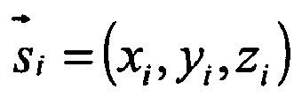

MATRICS algorithm 100 uses the Euclidean distance to find the closest corresponding point between the point clouds and uses this information to calculate a registration vector, which includes a translation vector and a rotation vector. The translation vector is used to translate a point cloud and the rotation vector is used to rotate a point cloud. The registration vectors and the corresponding unit rotation matrix are defined as follows:
- The function that the
MATRICS algorithm 100 uses to minimize the alignment error and compute the registration is:
 which corresponds to the maximum eigenvalue of the following matrix:


- The
MATRICS algorithm 100 also includes the functionality to interpolate data from one three-dimensional model to another. For example, in the case of heat transfer analyses, theMATRICS algorithm 100 is run two times in the loop. It is used to align the ANSYS model to the CFD model and interpolate temperatures from the ANSYS model to the CFD model. It is also used to align CFD model to the ANSYS model and interpolate the Heat Transfer Coefficient and pressures from the CFD model to the ANSYS model. Likewise, in the case of aero-mechanical analyses, theMATRICS algorithm 100 aligns the ANSYS model to the CFD model and interpolates the modal displacements from the ANSYS model to the CFD model. - While the invention has been described with reference to exemplary embodiments, it will be understood by those skilled in the art that various changes may be made and equivalents may be substituted for elements thereof without departing from the scope of the invention. In addition, many modifications may be made to adapt a particular situation or material to the teachings of the invention without departing from the essential scope thereof. Therefore, it is intended that the invention not be limited to the particular embodiment disclosed as the best or only mode contemplated for carrying out this invention, but that the invention will include all embodiments falling within the scope of the appended claims. Moreover, the use of the terms first, second, etc. do not denote any order or importance, but rather the terms first, second, etc. are used to distinguish one element from another. Furthermore, the use of the terms a, an, etc. do not denote a limitation of quantity, but rather denote the presence of at least one of the referenced item.
-
Three-dimensional models 10 Receive point clouds 12 Sample representative data set 14 Solve for local alignment error minima 16 Select representative minimum 18 Solve for global minimum 20 Interpolate data 22 MATRICS algorithm 100 Receive input 101 Data formatting 102 Merge CFD files 103 Extract point cloud 104 Pre-registration phase 105 Pick next guess 106 Compute correspondences 107 Sort correspondences 108 Trim largest correspondences 109 Apply pre-registration 111 Initial guesses solved 113 Select best solution 114 Apply pre-registration best solution 115 Registration phase 117 Compute correspondences 118 Sort correspondences 119 Trim largest correspondences 120 Compute registration 121 Apply registration 122 Converge 123 Interpolation phase 124 Register data 125 Interpolate data 126 Output files 127
Claims (10)
- A method of aligning three-dimensional models (10) comprises
receiving one or more point clouds (12) each indicative of a three-dimensional model (10);
sampling a representative data set (14) from said point clouds (12);
solving for a set of possible local alignment error minima (16) of said representative data sets (14);
selecting a representative minimum (18) from said set of possible local minima (16); and
solving for a global minimum (20) in alignment error of said point clouds (12) using said representative minimum (18) as an initial estimate. - The method of claim 1 further comprising interpolating a first data set (22) from a first three-dimensional model (10) to a second three-dimensional model (10).
- The method of claim 1 or claim 2 wherein said solving for a set of possible local alignment error minima (16) uses at a TrICP or ICP algorithm (107).
- The method of claim 2 or claim 3 when dependent thereon further comprising writing an output file including the interpolated data (22).
- A system for aligning three-dimensional models (10) comprising:means for receiving one or more point clouds (12) indicative of a three-dimensional model (10);means for sampling a representative data set (14) from said point clouds (12);means for solving for a set of possible local alignment error minima (16) of said representative data sets (14);means for selecting a representative minima (16) from said set of possible local minima (16); andmeans for solving for a global minima (16) in alignment of said point clouds (12) using said representative minima (16) as an initial estimate.
- The system of claim 5 further comprising interpolating a first data set (22) from a first three-dimensional model (10) to a second three-dimensional model (10).
- The system of claim 5 or claim 6 wherein said means solving for a set of possible local alignment error minima (16) uses at a TrICP or ICP algorithm (107).
- A computer program product for aligning three-dimensional models (10), the computer program product comprising instructions for performing:receiving one or more point clouds (12) each indicative of a three-dimensional model (10);sampling a representative data set (14) from said point clouds (12);solving for a set of possible local alignment error minima (16) of said representative data sets (14);selecting a representative minimum (18) from said set of possible local minima (16); andsolving for a global minimum (20) in alignment error of said point clouds (12) using said representative minimum as an initial estimate.
- The computer program product of claim 8 further comprising instructions for performing interpolation (124) of a first data set (126) from a first three-dimensional model (10) to a second three-dimensional model (10).
- The computer program product of claim 8 or claim 9 wherein said point clouds (12) each indicative of a three-dimensional model (10) are received from a ANSYS or a CFD software (101).
Applications Claiming Priority (1)
| Application Number | Priority Date | Filing Date | Title |
|---|---|---|---|
| US11/161,243 US20070024611A1 (en) | 2005-07-27 | 2005-07-27 | System and method for aligning three-dimensional models |
Publications (1)
| Publication Number | Publication Date |
|---|---|
| EP1748372A2 true EP1748372A2 (en) | 2007-01-31 |
Family
ID=37065477
Family Applications (1)
| Application Number | Title | Priority Date | Filing Date |
|---|---|---|---|
| EP06253872A Withdrawn EP1748372A2 (en) | 2005-07-27 | 2006-07-24 | System and method for aligning three-dimensional models |
Country Status (4)
| Country | Link |
|---|---|
| US (1) | US20070024611A1 (en) |
| EP (1) | EP1748372A2 (en) |
| JP (1) | JP2007035042A (en) |
| KR (1) | KR20070014084A (en) |
Families Citing this family (13)
| Publication number | Priority date | Publication date | Assignee | Title |
|---|---|---|---|---|
| US7289662B2 (en) * | 2002-12-07 | 2007-10-30 | Hrl Laboratories, Llc | Method and apparatus for apparatus for generating three-dimensional models from uncalibrated views |
| CN101063967B (en) * | 2006-04-28 | 2010-11-10 | 鸿富锦精密工业(深圳)有限公司 | Point cloud automatic pruning system and method |
| CN101387506B (en) * | 2007-09-14 | 2010-11-10 | 鸿富锦精密工业(深圳)有限公司 | Point cloud optimum alignment method |
| TWI402765B (en) * | 2007-09-28 | 2013-07-21 | Hon Hai Prec Ind Co Ltd | Method for aligning point clouds optimally |
| KR101665567B1 (en) * | 2010-05-20 | 2016-10-12 | 삼성전자주식회사 | Temporal interpolation of three dimension depth image method and apparatus |
| US9626462B2 (en) | 2014-07-01 | 2017-04-18 | 3M Innovative Properties Company | Detecting tooth wear using intra-oral 3D scans |
| US10192003B2 (en) | 2014-09-08 | 2019-01-29 | 3M Innovative Properties Company | Method of aligning intra-oral digital 3D models |
| US9737257B2 (en) | 2015-01-30 | 2017-08-22 | 3M Innovative Properties Company | Estimating and predicting tooth wear using intra-oral 3D scans |
| US10229533B2 (en) * | 2016-11-03 | 2019-03-12 | Mitsubishi Electric Research Laboratories, Inc. | Methods and systems for fast resampling method and apparatus for point cloud data |
| KR101925862B1 (en) * | 2018-09-13 | 2018-12-06 | 주식회사 에이엠오토노미 | Real-time 3d mapping using 3d-lidar |
| US11662469B2 (en) * | 2019-04-04 | 2023-05-30 | Denso International America, Inc. | System and method for merging clusters |
| CN113467238B (en) * | 2021-06-28 | 2023-03-21 | 燕山大学 | Watering control method for intelligent dry snow field |
| CN116416287A (en) * | 2022-11-25 | 2023-07-11 | 重庆理工大学 | Point cloud registration method, electronic equipment and storage medium based on feature description of key points and neighborhood point pairs |
Family Cites Families (4)
| Publication number | Priority date | Publication date | Assignee | Title |
|---|---|---|---|---|
| US6757423B1 (en) * | 1999-02-19 | 2004-06-29 | Barnes-Jewish Hospital | Methods of processing tagged MRI data indicative of tissue motion including 4-D LV tissue tracking |
| US20040222987A1 (en) * | 2003-05-08 | 2004-11-11 | Chang Nelson Liang An | Multiframe image processing |
| US7817829B2 (en) * | 2004-03-15 | 2010-10-19 | Koninklijke Philips Electronics N.V. | Image visualization |
| WO2006083297A2 (en) * | 2004-06-10 | 2006-08-10 | Sarnoff Corporation | Method and apparatus for aligning video to three-dimensional point clouds |
-
2005
- 2005-07-27 US US11/161,243 patent/US20070024611A1/en not_active Abandoned
-
2006
- 2006-07-24 EP EP06253872A patent/EP1748372A2/en not_active Withdrawn
- 2006-07-26 KR KR1020060070433A patent/KR20070014084A/en not_active Withdrawn
- 2006-07-26 JP JP2006202661A patent/JP2007035042A/en not_active Withdrawn
Also Published As
| Publication number | Publication date |
|---|---|
| KR20070014084A (en) | 2007-01-31 |
| JP2007035042A (en) | 2007-02-08 |
| US20070024611A1 (en) | 2007-02-01 |
Similar Documents
| Publication | Publication Date | Title |
|---|---|---|
| EP1748372A2 (en) | System and method for aligning three-dimensional models | |
| Papac et al. | Efficient symmetric discretization for the Poisson, heat and Stefan-type problems with Robin boundary conditions | |
| Fitzgibbon | Robust registration of 2D and 3D point sets | |
| Shephard et al. | Automatic three‐dimensional mesh generation by the finite octree technique | |
| Minion | Semi-implicit projection methods for incompressible flow based on spectral deferred corrections | |
| US20050175238A1 (en) | Process for drafting a curve in a computer-aided design system | |
| US10845779B2 (en) | Designing an outer surface of a composite part | |
| Neto et al. | Nagata patch interpolation using surface normal vectors evaluated from the IGES file | |
| US7107193B1 (en) | Defining parameters for a finite elements analysis calculation in a computer-assisted drafting program | |
| Kumar et al. | Volume deviation in direct slicing | |
| US6640201B1 (en) | Method for comparing points sets | |
| An et al. | Practical implementation of an End-to-end methodology for SPC of 3-D part geometry: A case study | |
| Kumar et al. | Computing offsets of trimmed NURBS surfaces | |
| Martin et al. | Non-manifold surface reconstruction from high-dimensional point cloud data | |
| Kpodzo et al. | An accurate time integration scheme for arbitrary rotation motion: application to metal forming simulation | |
| US20070229543A1 (en) | System for controlling deformation | |
| JP2002133423A (en) | New face image database registration device and recording medium | |
| JP2001076015A (en) | Mold design apparatus, method, and storage medium | |
| US6633665B1 (en) | Transformation method of three-dimensional object points onto two-dimensional image points for linear pushbroom images | |
| Anderson-Sprecher et al. | Spline estimation of paths using bearings-only tracking data | |
| JP3408114B2 (en) | Solid data correction device, solid data correction method, and recording medium | |
| Cardone et al. | Identifying similar parts for assisting cost estimation of prismatic machined parts | |
| Lee et al. | Multi-frame structure from motion using optical flow probability distributions | |
| US12347210B2 (en) | Lane edge fusion system for an autonomous vehicle | |
| Brock et al. | Discrete-expansions for linear interpolation functions |
Legal Events
| Date | Code | Title | Description |
|---|---|---|---|
| PUAI | Public reference made under article 153(3) epc to a published international application that has entered the european phase |
Free format text: ORIGINAL CODE: 0009012 |
|
| AK | Designated contracting states |
Kind code of ref document: A2 Designated state(s): AT BE BG CH CY CZ DE DK EE ES FI FR GB GR HU IE IS IT LI LT LU LV MC NL PL PT RO SE SI SK TR |
|
| AX | Request for extension of the european patent |
Extension state: AL BA HR MK YU |
|
| STAA | Information on the status of an ep patent application or granted ep patent |
Free format text: STATUS: THE APPLICATION IS DEEMED TO BE WITHDRAWN |
|
| 18D | Application deemed to be withdrawn |
Effective date: 20100202 |