EP1748176A1 - Diesel engine and ship and power plant using the same - Google Patents
Diesel engine and ship and power plant using the same Download PDFInfo
- Publication number
- EP1748176A1 EP1748176A1 EP04724854A EP04724854A EP1748176A1 EP 1748176 A1 EP1748176 A1 EP 1748176A1 EP 04724854 A EP04724854 A EP 04724854A EP 04724854 A EP04724854 A EP 04724854A EP 1748176 A1 EP1748176 A1 EP 1748176A1
- Authority
- EP
- European Patent Office
- Prior art keywords
- diesel engine
- crank
- bearing
- bearings
- lubricating oil
- Prior art date
- Legal status (The legal status is an assumption and is not a legal conclusion. Google has not performed a legal analysis and makes no representation as to the accuracy of the status listed.)
- Withdrawn
Links
- 239000010687 lubricating oil Substances 0.000 claims abstract description 33
- 239000011343 solid material Substances 0.000 claims description 30
- 239000003921 oil Substances 0.000 claims description 14
- 238000001514 detection method Methods 0.000 claims description 10
- 239000012634 fragment Substances 0.000 abstract description 70
- 239000002184 metal Substances 0.000 abstract description 4
- 229910052751 metal Inorganic materials 0.000 abstract description 4
- 150000002739 metals Chemical class 0.000 abstract description 4
- 229910000897 Babbitt (metal) Inorganic materials 0.000 description 17
- 238000007689 inspection Methods 0.000 description 13
- XEEYBQQBJWHFJM-UHFFFAOYSA-N Iron Chemical compound [Fe] XEEYBQQBJWHFJM-UHFFFAOYSA-N 0.000 description 4
- 238000007599 discharging Methods 0.000 description 2
- 230000000694 effects Effects 0.000 description 2
- 229910052742 iron Inorganic materials 0.000 description 2
- 238000012423 maintenance Methods 0.000 description 2
- 206010010904 Convulsion Diseases 0.000 description 1
- 229910001361 White metal Inorganic materials 0.000 description 1
- 230000002159 abnormal effect Effects 0.000 description 1
- 238000005259 measurement Methods 0.000 description 1
- 230000008447 perception Effects 0.000 description 1
- 239000007787 solid Substances 0.000 description 1
- -1 that is Substances 0.000 description 1
- 230000000007 visual effect Effects 0.000 description 1
- 239000010969 white metal Substances 0.000 description 1
Images


Classifications
-
- F—MECHANICAL ENGINEERING; LIGHTING; HEATING; WEAPONS; BLASTING
- F01—MACHINES OR ENGINES IN GENERAL; ENGINE PLANTS IN GENERAL; STEAM ENGINES
- F01M—LUBRICATING OF MACHINES OR ENGINES IN GENERAL; LUBRICATING INTERNAL COMBUSTION ENGINES; CRANKCASE VENTILATING
- F01M11/00—Component parts, details or accessories, not provided for in, or of interest apart from, groups F01M1/00 - F01M9/00
- F01M11/03—Mounting or connecting of lubricant purifying means relative to the machine or engine; Details of lubricant purifying means
-
- F—MECHANICAL ENGINEERING; LIGHTING; HEATING; WEAPONS; BLASTING
- F02—COMBUSTION ENGINES; HOT-GAS OR COMBUSTION-PRODUCT ENGINE PLANTS
- F02B—INTERNAL-COMBUSTION PISTON ENGINES; COMBUSTION ENGINES IN GENERAL
- F02B77/00—Component parts, details or accessories, not otherwise provided for
- F02B77/08—Safety, indicating, or supervising devices
-
- F—MECHANICAL ENGINEERING; LIGHTING; HEATING; WEAPONS; BLASTING
- F16—ENGINEERING ELEMENTS AND UNITS; GENERAL MEASURES FOR PRODUCING AND MAINTAINING EFFECTIVE FUNCTIONING OF MACHINES OR INSTALLATIONS; THERMAL INSULATION IN GENERAL
- F16C—SHAFTS; FLEXIBLE SHAFTS; ELEMENTS OR CRANKSHAFT MECHANISMS; ROTARY BODIES OTHER THAN GEARING ELEMENTS; BEARINGS
- F16C17/00—Sliding-contact bearings for exclusively rotary movement
- F16C17/12—Sliding-contact bearings for exclusively rotary movement characterised by features not related to the direction of the load
- F16C17/24—Sliding-contact bearings for exclusively rotary movement characterised by features not related to the direction of the load with devices affected by abnormal or undesired positions, e.g. for preventing overheating, for safety
Definitions
- the present invention relates to a large-scale diesel engine, a ship and a power plant using the same, and particularly to an instrument which can detect a bearing damage of the diesel engine.
- a large-scale diesel engine includes a crank shaft 103 in which a plurality of crank pins 101 are provided via crank arms 102 and opposite ends of the crank shaft 103, and intermediate shaft parts between adjacent crank arms 102 and 102 are respectively supported by a bedplate 111 via bearings 104.
- the respective bearings 104 are constituted by a lower body 105 supported on the bedplate 111 side, an upper body 106 as a cap, and semi-circular bearing metals (for example, white metal is used) 107 mounted inside the bodies 105 and 106.
- lubricating oil is supplied to the respective bearings 104, collected into an oil pan 112 provided at a lower position and circularly supplied to the bearings via a filter by an oil pump.
- the bearing 104 is damaged, specifically, a part of the bearing metal 107 is damaged and fragments thereof are dripped from a clearance with the crank arm 102 together with the lubricating oil, threatening the crank shaft 103 and the bearings 104 to suffer seizure.
- an objection of the present invention is to provide a diesel engine in which damaged places of the bearing of the crank shaft can be easily identified, and a ship and a power plant including the same.
- a diesel engine comprises: a crank shaft including crank pins respectively connected with a plurality of pistons by means of connecting rods, and supported by a bedplate via a plurality of bearings; a crank case covering an engine main body constituted by the foregoing component members; and an oil pan provided at a lower part of the crank case and collecting lubricating oil supplied to the respective bearings, characterized in that solid material collection members for receiving the lubricating oil dripping from the bearings and collecting solid materials contained in the lubricating oil are disposed at a lower position between the bearings each supporting a journal of the crank shaft and crank arms respectively fitted with the crank pins.
- the solid material collection members are disposed perpendicularly to the crank shaft within the crank case and held on the bedplate supporting the bearings via a holding member.
- the solid material collection members are disposed perpendicularly to the crank shaft within the crank case and supported on the oil pan via a supporting member.
- the solid material collection members are slanted within a vertical plane perpendicular to the crank shaft.
- a detection sensor for detecting solid materials is disposed within each solid material collection members, and a solid material collection judging device is provided for receiving a detection signal from the detection sensor to judge whether solid materials have been collected.
- a ship of the present invention includes each of the foregoing diesel engines.
- a power plant of the present invention includes each of the foregoing diesel engines so as to drive a power generator.
- the solid material collection members for collecting solid materials are disposed at the lower positions each between the bearing and the crank arm, so that if the solid material such as fragments of the bearing metal is collected within the fragment collection member due to the damage of the bearing, it is possible to find solid material such as remaining fragments of the bearing metal within the solid material collection member by an operator who checks the inside of the crank case through an inspection window during his/her maintenance/inspection work. Thus, it is possible to know the damage of the bearing, and to identify the damaged bearing according to the position where the solid material is found within the fragment collection member.
- Figs. 1 to 3 show structures of a main part of a diesel engine in accordance with the first embodiment of the present invention.
- a diesel engine for a large-scale ship is described as the diesel engine in accordance with the present invention.
- a diesel engine 1 includes a plurality of pistons (not shown), and each piston is connected to a crank shaft 3 for producing a torque via a connecting rod 2.
- crank shaft 3 a crank pin 4 connected to each connecting rod 2 is provided between left and right crank arms (a set of crank arms) 5 and 5, and at a position eccentric to a rotating center thereof, and an intermediate shaft portion 3a between opposite shaft end portions, and the adjacent crank arms 5 and 5 is supported by a bedplate 6 via bearings (main bearing) 7.
- a cylinder head having a cylinder housing a piston is provided, and a crank case 8 covering both sides of the connecting rods 2 and the crank shaft 3, and an oil pan 9 covering a lower part thereof are provided.
- a plurality of inspection windows 8b showing an internal part are provided on one side wall portion (for example, port side) 8a of the crank case 8 in response to a position of the crank pin 4.
- the respective bearings (for example, intermediate bearings inside the engine) 7 are constituted by a body (constituted by a lower body and an upper body acting as a cap) 11 and two divided bearing metals 12 disposed inside the body 11. In abnormal, an edge portion of the bearing metal 12 is worn and broken, and fragments of the bearing metal 12 are fallen off from the body 11.
- the diesel engine 1 includes a bearing damage detector 13 capable of collecting the fragments dripped together with lubricating oil and identifying the bearing 7 having a damaged bearing metal 12 by looking into an inside of the crank case 8 through the inspection window 8b.
- the bearing damage detector 13 is disposed, for example, at a lower position of a lower flange portion 6b of a crossbar member 6a of the bedplate supporting the bearing 7 and along the crossbar member 6a.
- the bearing damage detector 13 is constituted by a fragment collection member (a solid material collection member) 21 collecting the fragments (the solid materials) mixed (contained) in the lubricating oil and a pair of holding bars (holding members) 22 provided perpendicularly to the crank shaft 3 with a predetermined interval so as to hold the fragment collection member 21 at the lower flange portion 6b of the crossbar member 6a.
- the fragment collection member 21 is elongate in a direction perpendicular to the crank shaft 3 and is a trough-shaped vessel having a V-shaped cross section and having wall portions 21a at opposite ends thereof.
- a plurality of lubricating oil discharging holes 21b are formed in places of a central lower part of the fragment collection member 21.
- a size of the hole 21b is smaller than a shortest length of the fragments to be detected so as to catch the fragments.
- the fragments are dripped together with the lubricating oil supplied to the bearing 7 and entered into the fragment collection member 21 disposed in correspondence with the bearing 7.
- the lubricating oil entered into the fragment collection member 21 is dripped from the hole 21b formed at the lower position thereof to the oil pan 9 of the crank case 8 and the fragments mixed in the lubricating oil are collected within the fragment collection member 21. Moreover, the lubricating oil dripped on the oil pan 9 is supplied to each bearing through a filter by an oil pump.
- the operator can find remaining fragments in the fragment collection member 21 to know that the bearing 7 is damaged and identify the damaged bearing 7 by a position of the fragment collection member 21 where the fragments have been found, in maintenance.
- the operator merely inspects the inside through the inspection window 8b to know the damage of the bearing 7 and identify the damaged bearing 7.
- Figs. 4 to 6 show structures of a main part of a diesel engine in accordance with the second embodiment of the present invention.
- the bearing damage detector 31 in the diesel engine 1 is constituted by the fragment collection member (solid collection member) 32 disposed at the lower position of the lower flange portion 6b of the crossbar member 6a of the bedplate 6 supporting the bearing 7 (for example, the intermediate bearing) and along the crossbar member 6a to receive the lubricating oil dripped from the bearing 7 and collect the fragments (solid materials) mixed in the lubricating oil, and a pair of supporting bars (supporting members) 33 provided in the direction perpendicular to the crank shaft 3 with a predetermined interval for holding the fragment collection member 32 at the lower flange portion 6b of the crossbar member 6a.
- the fragment collection member 32 is a trough-shaped vessel having a V-shaped cross section and having an L shape in plan view. That is to say, this vessel is constituted by a lubricating oil receiving portion 32a elongated in a direction perpendicular to the crank shaft 3 and a guide portion 32b connected in a direction perpendicular to an end portion of the lubricating oil receiving portion 32a for leading the lubricating oil to the crank pin 4 side (adjacent to the inspection window).
- one end side (for example, a bow side, that is, a side opposite to the inspection window) of the lubricating oil receiving portion 32a is the wall portion 32c and a tip of the guide portion 32b connected to the other end side is a net portion 32d (for example, an iron net is used).
- the lubricating oil receiving portion 32a is slanted to lower the inspection window 8b side and the net portion 32d of the guide portion 32b is directed toward the crank pin 4 side, that is, the inspection window 8b side to lower the tip thereof.
- the fragments are also dripped with the lubricating oil within the fragment collection member 32 disposed in correspondence with the bearing 7.
- the lubricating oil flows onto the guide portion 32b within the lubricating oil receiving portion 32a and is dripped into the oil pan 9 from the net portion 32d at the end surface thereof.
- the fragments of the bearing metal 12 are mixed in the lubricating oil, the fragments of the bearing metal 12 are collected in the net portion 32d.
- the fragments since the fragments are gathered adjacent to the inspection window, the fragments can be found through the inspection window 8b more easily than the above-described configuration of the first embodiment.
- Figs. 7 and 8 show structures of a main part of a diesel engine in accordance with the third embodiment of the present invention.
- a bearing damage detector 41 in the diesel engine 1 is constituted by a fragment collection member (solid material collection member) 42 disposed at the lower position of the lower flange portion 6b of the crossbar member 6a of the bedplate 6 supporting the bearing 7 (i.e. the intermediate bearing) and along the crossbar member 6a to receive the lubricating oil dripped from the bearing 7 and collect the fragments (solid materials) mixed in the lubricating oil, and a pair of supporting bar (supporting member) 43 provided in a direction perpendicular to the crank shaft 3 with a predetermined interval for holding the fragment collection member 32 at the lower flange portion 6b of the crossbar member 6a.
- a fragment collection member solid material collection member
- the fragment collection member 42 is elongated in a direction perpendicular to the crank shaft 3 and is a trough-shaped vessel having a V-shaped cross section and having wall portions 42a at opposite ends thereof. Furthermore, a plurality of lubricating oil discharging holes 42b are formed in places of a central lower part of the fragment collection member 42. A size of the hole 42b is smaller than a shortest length of a fragment to be detected so as to catch the fragments.
- the fragments are also dripped into the fragment collection member 41 disposed in correspondence with the bearing 7 to obtain the same effect as the above-described first embodiment.
- Figs. 9 and 10 show structures of a main part of a diesel engine in accordance with the fourth embodiment of the present invention.
- a fragment collection member 52 in a bearing damage detector 51 of the diesel engine 1 is disposed at the lower position (two places of left and right sides of the diesel engine) of the crossbar member, and constituted by a rectangular frame member 52a (for example, a wire is used) hung via a hanging fixer 53 from the upper part of a slanted side wall portion 9a of the oil pan 9 and an iron net 52b having the V-shaped cross section.
- the fragments of the bearing metal are collected in the fragment collection member of the bearing damage detector in accordance with the above-described second embodiment, the fragments can be automatically detected. Accordingly, the part relating to the bearing damage detector is attentively described, based on the bearing damage detector described in the second embodiment.
- Figs. 11 and 12 show structures of a main part of a diesel engine in accordance with the fifth embodiment of the present invention.
- a bearing damage detector 61 of the diesel engine 1 includes a detection sensor (for example, an eddy current detection sensor is used) 62 for detecting a metal disposed just above the guide portion 32b of the fragment collection member 32 described in the second embodiment and a fragment collection judging device 63 which judges the fragments are dripped and collected within the fragment collection member 32 by inputting a signal detected in each detection sensor 62.
- a detection sensor for example, an eddy current detection sensor is used
- the fragment collection judging device 63 performs the judgment by comparing an output signal when there is no solid material, that is, fragment with a sensor output signal when the fragment is included in the detection range. Specifically, by accumulating variations of the output signal and time data, the fragment collection judging device 63 watches a progress thereof to perform the judgment.
- an alarm signal may be outputted and information such as light, sound and indication which can be identified by a human may be used.
- the cross section of the vessel as the fragment collection member is V-shaped, but not limited by this and may be semi-circular.
- a ship where the diesel engine described in each embodiment described above is mounted and an electric power facility constituted by a generator driven by the diesel engine in accordance with each embodiment may be included.
Landscapes
- Engineering & Computer Science (AREA)
- General Engineering & Computer Science (AREA)
- Mechanical Engineering (AREA)
- Chemical & Material Sciences (AREA)
- Combustion & Propulsion (AREA)
- Shafts, Cranks, Connecting Bars, And Related Bearings (AREA)
- Lubrication Details And Ventilation Of Internal Combustion Engines (AREA)
- Cylinder Crankcases Of Internal Combustion Engines (AREA)
Abstract
A diesel engine (1) mounted, for example, on a ship, including bearing damage detectors (13), in which fragment collection members (21) capable of receiving lubricating oil dripped from bearings (7) and collecting the fragments of bearing metals (12) mixed in the lubricating oil are disposed at a lower position between the bearings (7) supporting the shaft part of a crank shaft (3) and a crank arm (5) to which a crank pin (4) is fitted.
Description
- The present invention relates to a large-scale diesel engine, a ship and a power plant using the same, and particularly to an instrument which can detect a bearing damage of the diesel engine.
- As shown in Fig. 13, a large-scale diesel engine includes a
crank shaft 103 in which a plurality of crank pins 101 are provided via crankarms 102 and opposite ends of thecrank shaft 103, and intermediate shaft parts between adjacent crankarms bedplate 111 viabearings 104. - In addition, as shown in Figs. 14 and 15, the
respective bearings 104 are constituted by alower body 105 supported on thebedplate 111 side, anupper body 106 as a cap, and semi-circular bearing metals (for example, white metal is used) 107 mounted inside thebodies - Further, lubricating oil is supplied to the
respective bearings 104, collected into anoil pan 112 provided at a lower position and circularly supplied to the bearings via a filter by an oil pump. - However, in the large-scale diesel engine for a ship, the crank shaft is very long and is carefully provided on the
bedplate 111, but since a load to the bearing increases by an improvement of an output (high output) per volume of an engine in itself and an allowable range for mounting is very tight, a mounting failure can be easily brought. - In case that the diesel engine is operated for a long time when the engine failure occurs, the
bearing 104 is damaged, specifically, a part of the bearingmetal 107 is damaged and fragments thereof are dripped from a clearance with thecrank arm 102 together with the lubricating oil, threatening thecrank shaft 103 and thebearings 104 to suffer seizure. - As described above, operation is hindered when the bearing
metal 107 is damaged, so that it is usual to visually check whether the fragments of the bearingmetal 107 have entered into the crankcase 108 and dripped into theoil pan 112, by looking into an internal part through aninspection window 108b provided adjacent to a lower position of aside wall portion 108a on a port side of a crankcase 108 or by entering into the crankcase 108. - In case that the fragments are found by visual checking, a failure occurrence is confirmed, but the lubricating oil mixed with the fragments moves within the
oil pan 112, which makes it difficult to identify which parts of thebearing 104 are damaged. - Thus, conventionally, an operator entered the crank
case 108, and inserted a micro measurement gauge through the clearance of only 10mm between thecrank arm 102 and thebearing 104 to identify damaged places, depending on longtime experiences and perceptions. - However, there are problems that performing this operation in the small crank
case 108 is very difficult and much time is required. - Therefore, an objection of the present invention is to provide a diesel engine in which damaged places of the bearing of the crank shaft can be easily identified, and a ship and a power plant including the same.
- A diesel engine comprises: a crank shaft including crank pins respectively connected with a plurality of pistons by means of connecting rods, and supported by a bedplate via a plurality of bearings; a crank case covering an engine main body constituted by the foregoing component members; and an oil pan provided at a lower part of the crank case and collecting lubricating oil supplied to the respective bearings, characterized in that solid material collection members for receiving the lubricating oil dripping from the bearings and collecting solid materials contained in the lubricating oil are disposed at a lower position between the bearings each supporting a journal of the crank shaft and crank arms respectively fitted with the crank pins.
- In the diesel engine of the present invention, the solid material collection members are disposed perpendicularly to the crank shaft within the crank case and held on the bedplate supporting the bearings via a holding member.
- In another diesel engine of the present invention, the solid material collection members are disposed perpendicularly to the crank shaft within the crank case and supported on the oil pan via a supporting member.
- In still another diesel engine of the present invention, the solid material collection members are slanted within a vertical plane perpendicular to the crank shaft.
- In still another diesel engine of the present invention, a detection sensor for detecting solid materials is disposed within each solid material collection members, and a solid material collection judging device is provided for receiving a detection signal from the detection sensor to judge whether solid materials have been collected.
- Further, a ship of the present invention includes each of the foregoing diesel engines.
- Furthermore, a power plant of the present invention includes each of the foregoing diesel engines so as to drive a power generator.
- According to the configuration of the diesel engine, the solid material collection members for collecting solid materials are disposed at the lower positions each between the bearing and the crank arm, so that if the solid material such as fragments of the bearing metal is collected within the fragment collection member due to the damage of the bearing, it is possible to find solid material such as remaining fragments of the bearing metal within the solid material collection member by an operator who checks the inside of the crank case through an inspection window during his/her maintenance/inspection work. Thus, it is possible to know the damage of the bearing, and to identify the damaged bearing according to the position where the solid material is found within the fragment collection member.
-
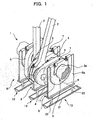
- Fig. 1 is a perspective view of a diesel engine in accordance with a first embodiment of the present invention;
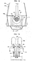
- Fig. 2 is a cross-sectional view of a main part of the diesel engine;
- Fig. 3 is a cross-sectional view taken along the line A-A in Fig. 2;
- Fig. 4 is a cross-sectional view of a main part of a diesel engine in accordance with a second embodiment of the present invention;
- Fig. 5 is a cross-sectional view taken along the line B-B in Fig. 4;
- Fig. 6 is a perspective view taken along the line C-C in Fig. 5;
- Fig. 7 is a cross-sectional view of a main part of a diesel engine in accordance with a third embodiment of the present invention;
- Fig. 8 is a cross-sectional view taken along the line D-D in Fig. 7;
- Fig. 9 is a cross-sectional view of a main part of a diesel engine in accordance with a fourth embodiment of the present invention;
- Fig. 10 is a cross-sectional view taken along the line E-E in Fig. 9;
- Fig. 11 is a cross-sectional view of a main part of a diesel engine in accordance with a fifth embodiment of the present invention;
- Fig. 12 is a perspective view taken along the line F-F in Fig. 11;
- Fig. 13 is a perspective view of a diesel engine of a prior art;
- Fig. 14 is a cross-sectional view of a main part of the diesel engine; and
- Fig. 15 is a cross-sectional view taken along the line G-G in Fig. 14.
- The present invention will be described in detail with reference to the accompanying drawings.
- First of all, a diesel engine in accordance with a first embodiment of the present invention will be described with reference to Figs. 1 to 3.
- Figs. 1 to 3 show structures of a main part of a diesel engine in accordance with the first embodiment of the present invention.
- A diesel engine for a large-scale ship is described as the diesel engine in accordance with the present invention.
- As shown in Figs. 1 to 3, a
diesel engine 1 includes a plurality of pistons (not shown), and each piston is connected to acrank shaft 3 for producing a torque via a connectingrod 2. - In the
crank shaft 3, a crank pin 4 connected to each connectingrod 2 is provided between left and right crank arms (a set of crank arms) 5 and 5, and at a position eccentric to a rotating center thereof, and anintermediate shaft portion 3a between opposite shaft end portions, and theadjacent crank arms bedplate 6 via bearings (main bearing) 7. - In an upper part of the
bedplate 6 supporting thecrank shaft 3, a cylinder head having a cylinder housing a piston is provided, and acrank case 8 covering both sides of the connectingrods 2 and thecrank shaft 3, and anoil pan 9 covering a lower part thereof are provided. - A plurality of
inspection windows 8b showing an internal part are provided on one side wall portion (for example, port side) 8a of thecrank case 8 in response to a position of the crank pin 4. - The respective bearings (for example, intermediate bearings inside the engine) 7 are constituted by a body (constituted by a lower body and an upper body acting as a cap) 11 and two divided bearing
metals 12 disposed inside thebody 11. In abnormal, an edge portion of thebearing metal 12 is worn and broken, and fragments of thebearing metal 12 are fallen off from thebody 11. - Thus, the
diesel engine 1 includes abearing damage detector 13 capable of collecting the fragments dripped together with lubricating oil and identifying thebearing 7 having a damaged bearingmetal 12 by looking into an inside of thecrank case 8 through theinspection window 8b. - The
bearing damage detector 13 is disposed, for example, at a lower position of alower flange portion 6b of acrossbar member 6a of the bedplate supporting thebearing 7 and along thecrossbar member 6a. Thebearing damage detector 13 is constituted by a fragment collection member (a solid material collection member) 21 collecting the fragments (the solid materials) mixed (contained) in the lubricating oil and a pair of holding bars (holding members) 22 provided perpendicularly to thecrank shaft 3 with a predetermined interval so as to hold thefragment collection member 21 at thelower flange portion 6b of thecrossbar member 6a. - The
fragment collection member 21 is elongate in a direction perpendicular to thecrank shaft 3 and is a trough-shaped vessel having a V-shaped cross section and havingwall portions 21a at opposite ends thereof. A plurality of lubricatingoil discharging holes 21b are formed in places of a central lower part of thefragment collection member 21. A size of thehole 21b is smaller than a shortest length of the fragments to be detected so as to catch the fragments. - Accordingly, in case that the end portion of the bearing
metal 12 is worn and the fragments are produced during driving thediesel engine 1, the fragments are dripped together with the lubricating oil supplied to thebearing 7 and entered into thefragment collection member 21 disposed in correspondence with thebearing 7. - The lubricating oil entered into the
fragment collection member 21 is dripped from thehole 21b formed at the lower position thereof to theoil pan 9 of thecrank case 8 and the fragments mixed in the lubricating oil are collected within thefragment collection member 21. Moreover, the lubricating oil dripped on theoil pan 9 is supplied to each bearing through a filter by an oil pump. - As described above, in case that the fragments of the bearing
metal 12 are collected within thefragment collection member 21 due to the damage of thebearing 7, when an operator checks the inside of thecrank case 8 through theinspection window 8b, the operator can find remaining fragments in thefragment collection member 21 to know that thebearing 7 is damaged and identify the damagedbearing 7 by a position of thefragment collection member 21 where the fragments have been found, in maintenance. - That is to say, in case that the bearing
metal 12 of thebearing 7 is damaged, the operator merely inspects the inside through theinspection window 8b to know the damage of thebearing 7 and identify the damagedbearing 7. - Next, a diesel engine in accordance with a second embodiment of the present invention will be described with reference to the drawings.
- Moreover, since a portion of the second embodiment different from the first embodiment is the bearing damage detector, the portion will be attentively described and the description of other component members will be omitted by using part numbers described in the first embodiment.
- Figs. 4 to 6 show structures of a main part of a diesel engine in accordance with the second embodiment of the present invention.
- As shown in Figs. 4 to 6, the
bearing damage detector 31 in thediesel engine 1 is constituted by the fragment collection member (solid collection member) 32 disposed at the lower position of thelower flange portion 6b of thecrossbar member 6a of thebedplate 6 supporting the bearing 7 (for example, the intermediate bearing) and along thecrossbar member 6a to receive the lubricating oil dripped from thebearing 7 and collect the fragments (solid materials) mixed in the lubricating oil, and a pair of supporting bars (supporting members) 33 provided in the direction perpendicular to thecrank shaft 3 with a predetermined interval for holding thefragment collection member 32 at thelower flange portion 6b of thecrossbar member 6a. - However, the
fragment collection member 32 is a trough-shaped vessel having a V-shaped cross section and having an L shape in plan view. That is to say, this vessel is constituted by a lubricatingoil receiving portion 32a elongated in a direction perpendicular to the crankshaft 3 and aguide portion 32b connected in a direction perpendicular to an end portion of the lubricatingoil receiving portion 32a for leading the lubricating oil to the crank pin 4 side (adjacent to the inspection window). - In addition, one end side (for example, a bow side, that is, a side opposite to the inspection window) of the lubricating
oil receiving portion 32a is thewall portion 32c and a tip of theguide portion 32b connected to the other end side is anet portion 32d (for example, an iron net is used). - Moreover, the lubricating
oil receiving portion 32a is slanted to lower theinspection window 8b side and thenet portion 32d of theguide portion 32b is directed toward the crank pin 4 side, that is, theinspection window 8b side to lower the tip thereof. - Therefore, in case that the end portion of the bearing
metal 12 in thebearing 7 is worn and the fragments are produced during driving thediesel engine 1, the fragments are also dripped with the lubricating oil within thefragment collection member 32 disposed in correspondence with thebearing 7. - The lubricating oil flows onto the
guide portion 32b within the lubricatingoil receiving portion 32a and is dripped into theoil pan 9 from thenet portion 32d at the end surface thereof. - And in case that the fragments of the bearing
metal 12 are mixed in the lubricating oil, the fragments of the bearingmetal 12 are collected in thenet portion 32d. - That is to say, since the fragments are gathered adjacent to the inspection window, the fragments can be found through the
inspection window 8b more easily than the above-described configuration of the first embodiment. - Next, a diesel engine in accordance with a third embodiment of the present invention will be described with reference to the drawings.
- Moreover, since a portion of the third embodiment different from the first embodiment is the bearing damage detector, the portion will be attentively described and the description of other component members will be omitted by using the part numbers described in the first embodiment.
- Figs. 7 and 8 show structures of a main part of a diesel engine in accordance with the third embodiment of the present invention.
- As shown in Figs. 7 to 8, a
bearing damage detector 41 in thediesel engine 1 is constituted by a fragment collection member (solid material collection member) 42 disposed at the lower position of thelower flange portion 6b of thecrossbar member 6a of thebedplate 6 supporting the bearing 7 (i.e. the intermediate bearing) and along thecrossbar member 6a to receive the lubricating oil dripped from thebearing 7 and collect the fragments (solid materials) mixed in the lubricating oil, and a pair of supporting bar (supporting member) 43 provided in a direction perpendicular to the crankshaft 3 with a predetermined interval for holding thefragment collection member 32 at thelower flange portion 6b of thecrossbar member 6a. - Similar to the first embodiment, the
fragment collection member 42 is elongated in a direction perpendicular to the crankshaft 3 and is a trough-shaped vessel having a V-shaped cross section and havingwall portions 42a at opposite ends thereof. Furthermore, a plurality of lubricatingoil discharging holes 42b are formed in places of a central lower part of thefragment collection member 42. A size of thehole 42b is smaller than a shortest length of a fragment to be detected so as to catch the fragments. - Therefore, in case that the end portion of the bearing
metal 12 in thebearing 7 is worn and the fragments are produced during driving thediesel engine 1, the fragments are also dripped into thefragment collection member 41 disposed in correspondence with thebearing 7 to obtain the same effect as the above-described first embodiment. - Next, a diesel engine in accordance with a fourth embodiment of the present invention will be described with reference to the drawings.
- Moreover, since a portion of the fourth embodiment different from the first embodiment is the bearing damage detector, the portion will be attentively described and the description of other component members will be omitted by using the part numbers described in the first embodiment.
- Figs. 9 and 10 show structures of a main part of a diesel engine in accordance with the fourth embodiment of the present invention.
- As shown in Figs. 9 and 10, a
fragment collection member 52 in abearing damage detector 51 of thediesel engine 1 is disposed at the lower position (two places of left and right sides of the diesel engine) of the crossbar member, and constituted by a rectangular frame member 52a (for example, a wire is used) hung via a hangingfixer 53 from the upper part of a slantedside wall portion 9a of theoil pan 9 and an iron net 52b having the V-shaped cross section. - In this case, when the fragments of the bearing
metal 12 in thebearing 7 are dripped into thefragment collection member 52 together with the lubricating oil, the only fragments are also collected to obtain the same effect as the above-described first embodiment. - Next, a diesel engine in accordance with a fifth embodiment of the present invention will be described with reference to the drawings.
- In the diesel engine in accordance with the fifth embodiment, in case that the fragments of the bearing metal are collected in the fragment collection member of the bearing damage detector in accordance with the above-described second embodiment, the fragments can be automatically detected. Accordingly, the part relating to the bearing damage detector is attentively described, based on the bearing damage detector described in the second embodiment.
- Figs. 11 and 12 show structures of a main part of a diesel engine in accordance with the fifth embodiment of the present invention.
- That is to say, a
bearing damage detector 61 of thediesel engine 1 includes a detection sensor (for example, an eddy current detection sensor is used) 62 for detecting a metal disposed just above theguide portion 32b of thefragment collection member 32 described in the second embodiment and a fragmentcollection judging device 63 which judges the fragments are dripped and collected within thefragment collection member 32 by inputting a signal detected in eachdetection sensor 62. - The fragment
collection judging device 63 performs the judgment by comparing an output signal when there is no solid material, that is, fragment with a sensor output signal when the fragment is included in the detection range. Specifically, by accumulating variations of the output signal and time data, the fragmentcollection judging device 63 watches a progress thereof to perform the judgment. - Moreover, in case that fragments are detected by the fragment
collection judging device 63, an alarm signal may be outputted and information such as light, sound and indication which can be identified by a human may be used. - However, in each embodiment described above, the cross section of the vessel as the fragment collection member is V-shaped, but not limited by this and may be semi-circular.
- Furthermore, as other embodiments of the present invention, a ship where the diesel engine described in each embodiment described above is mounted and an electric power facility constituted by a generator driven by the diesel engine in accordance with each embodiment may be included.
Claims (7)
- A diesel engine comprising:a crank shaft including crank pins respectively connected with a plurality of pistons by connecting rods, and supported by a bedplate via a plurality of bearings;a crank case covering an engine main body constituted by the component members; andan oil pan provided at a lower part of the crank case and collecting lubricating oil supplied to the respective bearings, characterized in thatsolid material collection members for receiving the lubricating oil dripping from the bearings and collecting solid materials contained in the lubricating oil are disposed at a lower position between the bearings each supporting a journal of the crank shaft and crank arms respectively fitted with the crank pins.
- The diesel engine according to claim 1, wherein the solid material collection members are disposed perpendicularly to the crank shaft within the crank case and held on the bedplate supporting the bearings via a holding member.
- The diesel engine according to claim 1, wherein the solid material collection members are disposed perpendicularly to the crank shaft within the crank case and supported on the oil pan via a supporting member.
- The diesel engine according to any one of claims 1 to 3, wherein the solid material collection members are slanted within a vertical plane perpendicular to the crank shaft.
- The diesel engine according to any one of claims 1 to 4, wherein a detection sensor for detecting solid materials is disposed within each solid material collection member, and a solid material collection judging device is provided for receiving a detection signal from the detection sensor to judge whether solid materials have been collected.
- A ship including the diesel engine according to any one of claims 1 to 5.
- A power plant including the diesel engine according to any one of claims 1 to 5 to drive a power generator.
Applications Claiming Priority (1)
| Application Number | Priority Date | Filing Date | Title |
|---|---|---|---|
| PCT/JP2004/004732 WO2005100770A1 (en) | 2004-03-31 | 2004-03-31 | Diesel engine and ship and power plant using the same |
Publications (1)
| Publication Number | Publication Date |
|---|---|
| EP1748176A1 true EP1748176A1 (en) | 2007-01-31 |
Family
ID=35150055
Family Applications (1)
| Application Number | Title | Priority Date | Filing Date |
|---|---|---|---|
| EP04724854A Withdrawn EP1748176A1 (en) | 2004-03-31 | 2004-03-31 | Diesel engine and ship and power plant using the same |
Country Status (4)
| Country | Link |
|---|---|
| EP (1) | EP1748176A1 (en) |
| JP (1) | JPWO2005100770A1 (en) |
| CN (1) | CN1926319A (en) |
| WO (1) | WO2005100770A1 (en) |
Family Cites Families (2)
| Publication number | Priority date | Publication date | Assignee | Title |
|---|---|---|---|---|
| JPH0714108U (en) * | 1993-08-06 | 1995-03-10 | 株式会社豊田自動織機製作所 | Suction filter |
| JP3628644B2 (en) * | 2001-11-20 | 2005-03-16 | 川崎重工業株式会社 | Crank journal bearing device |
-
2004
- 2004-03-31 CN CNA2004800426102A patent/CN1926319A/en active Pending
- 2004-03-31 EP EP04724854A patent/EP1748176A1/en not_active Withdrawn
- 2004-03-31 JP JP2006512176A patent/JPWO2005100770A1/en active Pending
- 2004-03-31 WO PCT/JP2004/004732 patent/WO2005100770A1/en not_active Ceased
Non-Patent Citations (1)
| Title |
|---|
| See references of WO2005100770A1 * |
Also Published As
| Publication number | Publication date |
|---|---|
| WO2005100770A1 (en) | 2005-10-27 |
| CN1926319A (en) | 2007-03-07 |
| JPWO2005100770A1 (en) | 2008-03-06 |
Similar Documents
| Publication | Publication Date | Title |
|---|---|---|
| EP0982579B1 (en) | Device for inspecting bearings of main motors of rolling stock | |
| ES2226100T3 (en) | SYSTEM FOR A PREDICTIVE DIAGNOSIS OF MACHINE PARTS. | |
| DE4225783C2 (en) | Device for monitoring the wear-related wear of an axial bearing in a submersible pump | |
| US20170248572A1 (en) | Lubricant condition assessment system | |
| WO2004063680A2 (en) | Multiple discriminate analysis and data integration of vibration in rotation machinery | |
| KR20130112540A (en) | Bearing wear condition monitoring, diagnosis and estimation system and method for the low speed diesel engine | |
| KR20110009615A (en) | Data collection device and diagnostic device of the equipment equipped with the data collection device | |
| KR101229949B1 (en) | With bearing worn down condition surveillance system and that system of vessel engine inside worn down condition the method which watches | |
| EP3361229A3 (en) | System and method for blade health monitoring | |
| KR20190121333A (en) | Condition diagnosis system and condition diagnosis method of cloud guidance device | |
| EP1748176A1 (en) | Diesel engine and ship and power plant using the same | |
| KR102346012B1 (en) | Chanin diagnostic apparatus and method | |
| CN111983015A (en) | Vehicle frame weld joint detection system and detection method | |
| KR100808080B1 (en) | Diesel engines and ships and power plants using them | |
| CN110500268B (en) | Reciprocating compressor reverse angle detection system based on indicator diagram | |
| KR20060017666A (en) | Residual Life Diagnosis Apparatus and Method for Fatigue Measurement of Structures | |
| KR20220064841A (en) | A iron sensor capable of sensing and measuring iron using eddy current | |
| CN115839781B (en) | Bearing temperature monitoring device | |
| JP7359378B2 (en) | Information board anomaly detection system | |
| CN115977936A (en) | Reciprocating compressor fault diagnosis system | |
| Kuoppala et al. | Condition monitoring methods for rotating machinery | |
| JP7270189B2 (en) | Conversion factor calculation method | |
| KR102960113B1 (en) | Test system | |
| US10088380B2 (en) | Method and system for a sample filter visual contamination check | |
| JPH08338220A (en) | Magnetic plug with alarm sensor |
Legal Events
| Date | Code | Title | Description |
|---|---|---|---|
| PUAI | Public reference made under article 153(3) epc to a published international application that has entered the european phase |
Free format text: ORIGINAL CODE: 0009012 |
|
| 17P | Request for examination filed |
Effective date: 20061031 |
|
| AK | Designated contracting states |
Kind code of ref document: A1 Designated state(s): AT BE BG CH CY CZ DE DK EE ES FI FR GB GR HU IE IT LI LU MC NL PL PT RO SE SI SK TR |
|
| DAX | Request for extension of the european patent (deleted) | ||
| STAA | Information on the status of an ep patent application or granted ep patent |
Free format text: STATUS: THE APPLICATION IS DEEMED TO BE WITHDRAWN |
|
| 18D | Application deemed to be withdrawn |
Effective date: 20091001 |