EP1747850B1 - Apparatus for and method of producing buff tapes - Google Patents
Apparatus for and method of producing buff tapes Download PDFInfo
- Publication number
- EP1747850B1 EP1747850B1 EP06253873A EP06253873A EP1747850B1 EP 1747850 B1 EP1747850 B1 EP 1747850B1 EP 06253873 A EP06253873 A EP 06253873A EP 06253873 A EP06253873 A EP 06253873A EP 1747850 B1 EP1747850 B1 EP 1747850B1
- Authority
- EP
- European Patent Office
- Prior art keywords
- buff
- tapes
- tape
- guide roller
- wiping
- Prior art date
- Legal status (The legal status is an assumption and is not a legal conclusion. Google has not performed a legal analysis and makes no representation as to the accuracy of the status listed.)
- Not-in-force
Links
- 238000000034 method Methods 0.000 title claims description 20
- 230000006835 compression Effects 0.000 claims abstract description 30
- 238000007906 compression Methods 0.000 claims abstract description 30
- 239000002245 particle Substances 0.000 claims abstract description 27
- 239000000758 substrate Substances 0.000 abstract description 7
- 238000004804 winding Methods 0.000 abstract description 5
- 238000009499 grossing Methods 0.000 abstract description 3
- 238000005498 polishing Methods 0.000 abstract description 3
- 238000004519 manufacturing process Methods 0.000 description 7
- 239000000463 material Substances 0.000 description 7
- 239000000428 dust Substances 0.000 description 4
- 239000004744 fabric Substances 0.000 description 4
- JOYRKODLDBILNP-UHFFFAOYSA-N Ethyl urethane Chemical compound CCOC(N)=O JOYRKODLDBILNP-UHFFFAOYSA-N 0.000 description 2
- 238000004140 cleaning Methods 0.000 description 2
- 239000011538 cleaning material Substances 0.000 description 2
- 238000000576 coating method Methods 0.000 description 2
- 230000002093 peripheral effect Effects 0.000 description 2
- OKTJSMMVPCPJKN-UHFFFAOYSA-N Carbon Chemical compound [C] OKTJSMMVPCPJKN-UHFFFAOYSA-N 0.000 description 1
- 239000004677 Nylon Substances 0.000 description 1
- 229910000831 Steel Inorganic materials 0.000 description 1
- 230000002159 abnormal effect Effects 0.000 description 1
- 229910052782 aluminium Inorganic materials 0.000 description 1
- XAGFODPZIPBFFR-UHFFFAOYSA-N aluminium Chemical compound [Al] XAGFODPZIPBFFR-UHFFFAOYSA-N 0.000 description 1
- 239000011230 binding agent Substances 0.000 description 1
- 229910052799 carbon Inorganic materials 0.000 description 1
- 239000011248 coating agent Substances 0.000 description 1
- 239000011521 glass Substances 0.000 description 1
- 239000010985 leather Substances 0.000 description 1
- 230000001050 lubricating effect Effects 0.000 description 1
- 229910052751 metal Inorganic materials 0.000 description 1
- 239000002184 metal Substances 0.000 description 1
- 239000004745 nonwoven fabric Substances 0.000 description 1
- 229920001778 nylon Polymers 0.000 description 1
- TWNQGVIAIRXVLR-UHFFFAOYSA-N oxo(oxoalumanyloxy)alumane Chemical compound O=[Al]O[Al]=O TWNQGVIAIRXVLR-UHFFFAOYSA-N 0.000 description 1
- 239000000123 paper Substances 0.000 description 1
- 229920000728 polyester Polymers 0.000 description 1
- 230000001681 protective effect Effects 0.000 description 1
- 229910052710 silicon Inorganic materials 0.000 description 1
- 239000010703 silicon Substances 0.000 description 1
- 239000010959 steel Substances 0.000 description 1
Images

Classifications
-
- B—PERFORMING OPERATIONS; TRANSPORTING
- B24—GRINDING; POLISHING
- B24D—TOOLS FOR GRINDING, BUFFING OR SHARPENING
- B24D11/00—Constructional features of flexible abrasive materials; Special features in the manufacture of such materials
- B24D11/008—Finishing manufactured abrasive sheets, e.g. cutting, deforming
-
- B—PERFORMING OPERATIONS; TRANSPORTING
- B08—CLEANING
- B08B—CLEANING IN GENERAL; PREVENTION OF FOULING IN GENERAL
- B08B1/00—Cleaning by methods involving the use of tools
- B08B1/30—Cleaning by methods involving the use of tools by movement of cleaning members over a surface
-
- B—PERFORMING OPERATIONS; TRANSPORTING
- B26—HAND CUTTING TOOLS; CUTTING; SEVERING
- B26D—CUTTING; DETAILS COMMON TO MACHINES FOR PERFORATING, PUNCHING, CUTTING-OUT, STAMPING-OUT OR SEVERING
- B26D1/00—Cutting through work characterised by the nature or movement of the cutting member or particular materials not otherwise provided for; Apparatus or machines therefor; Cutting members therefor
- B26D1/01—Cutting through work characterised by the nature or movement of the cutting member or particular materials not otherwise provided for; Apparatus or machines therefor; Cutting members therefor involving a cutting member which does not travel with the work
- B26D1/12—Cutting through work characterised by the nature or movement of the cutting member or particular materials not otherwise provided for; Apparatus or machines therefor; Cutting members therefor involving a cutting member which does not travel with the work having a cutting member moving about an axis
- B26D1/14—Cutting through work characterised by the nature or movement of the cutting member or particular materials not otherwise provided for; Apparatus or machines therefor; Cutting members therefor involving a cutting member which does not travel with the work having a cutting member moving about an axis with a circular cutting member, e.g. disc cutter
- B26D1/24—Cutting through work characterised by the nature or movement of the cutting member or particular materials not otherwise provided for; Apparatus or machines therefor; Cutting members therefor involving a cutting member which does not travel with the work having a cutting member moving about an axis with a circular cutting member, e.g. disc cutter coacting with another disc cutter
- B26D1/245—Cutting through work characterised by the nature or movement of the cutting member or particular materials not otherwise provided for; Apparatus or machines therefor; Cutting members therefor involving a cutting member which does not travel with the work having a cutting member moving about an axis with a circular cutting member, e.g. disc cutter coacting with another disc cutter for thin material, e.g. for sheets, strips or the like
-
- B—PERFORMING OPERATIONS; TRANSPORTING
- B65—CONVEYING; PACKING; STORING; HANDLING THIN OR FILAMENTARY MATERIAL
- B65H—HANDLING THIN OR FILAMENTARY MATERIAL, e.g. SHEETS, WEBS, CABLES
- B65H18/00—Winding webs
- B65H18/08—Web-winding mechanisms
- B65H18/10—Mechanisms in which power is applied to web-roll spindle
- B65H18/106—Mechanisms in which power is applied to web-roll spindle for several juxtaposed strips
-
- B—PERFORMING OPERATIONS; TRANSPORTING
- B65—CONVEYING; PACKING; STORING; HANDLING THIN OR FILAMENTARY MATERIAL
- B65H—HANDLING THIN OR FILAMENTARY MATERIAL, e.g. SHEETS, WEBS, CABLES
- B65H35/00—Delivering articles from cutting or line-perforating machines; Article or web delivery apparatus incorporating cutting or line-perforating devices, e.g. adhesive tape dispensers
- B65H35/02—Delivering articles from cutting or line-perforating machines; Article or web delivery apparatus incorporating cutting or line-perforating devices, e.g. adhesive tape dispensers from or with longitudinal slitters or perforators
-
- B—PERFORMING OPERATIONS; TRANSPORTING
- B65—CONVEYING; PACKING; STORING; HANDLING THIN OR FILAMENTARY MATERIAL
- B65H—HANDLING THIN OR FILAMENTARY MATERIAL, e.g. SHEETS, WEBS, CABLES
- B65H2301/00—Handling processes for sheets or webs
- B65H2301/50—Auxiliary process performed during handling process
- B65H2301/51—Modifying a characteristic of handled material
- B65H2301/511—Processing surface of handled material upon transport or guiding thereof, e.g. cleaning
- B65H2301/5115—Cleaning
Definitions
- This invention relates to an apparatus for and a method of producing buff tapes as per the preamble of claims 1 and 10 respectively, for smoothing the surface of a magnetic disk substrate and more particularly to an apparatus and method for removing small loose debris particles of 0.3 ⁇ m - 5 ⁇ m in size when such buff tapes are produced from a mother tape by slitting it longitudinally.
- JP 63-047 069 An example of such an apparatus and of such a method is disclosed by JP 63-047 069 .
- a magnetic disk substrate is generally produced by forming layers of metal and magnetic coatings on an aluminum or glass substrate and finally forming a layer of carbon and a lubricating protective over-coating.
- a surface smoothing process is carried out by using a buff tape (or polishing tape) to remove the abnormal protrusions which are inevitably present as described, for example, in Japanese Patent Publication Tokko 2-10486 .
- a common problem with the use of such a buff tape has been the unwanted presence of small loose particles in the buff tape itself because such small loose particles on the hard disk substrate tend to crash into the magnetic head or become caught under it so as to effectively scratch or become embedded in the disk surface.
- the major cause of the presence of such loose particles in the buff tape was in its production process, or the process of slitting a mother tape which is produced typically with a width of 100mm to 1000mm and is slit longitudinally to obtain individual buff tapes typically having a width of 0.25 inches to 1.5 inches.
- Examples of prior art methods for removing such unwanted loose debris particles from buff tapes after obtained by slitting a much wider mother tape include the use of a tacky roller to force the loose particles to get stuck on its surface but the tacky roller material such as including silicon and/or urethane is commonly rejected in the list of materials that may be used or make contact with consumable products for hard disk substrate manufacturing.
- Another prior art method includes a wiping cloth and a vacuum device to suck up and trap the loose particles in the cloth material but the action of the wiping cloth and the vacuum causes the winding of the rolls to become uneven, loose and/or shifted. Also, the vacuum in a clean room environment upsets the laminar flow of the clean air and effectively causes debris and other particulates to enter the work area.
- JP 63-047069 discloses an apparatus for the manufacture of abrasive tape. Tape is fed from a supply roller to a final dress roller via a number of intermediate contact rollers.
- a cleaning material such as a non-woven fabric, leather or paper is wound around a contact roller and pressed against the tape as it is drawn from the supply roller to the final dress roller. Dust particles and the like are removed from the abrasive tape by adhering to the cleaning material.
- JP 63-214911 discloses a magnetic tape cleaning apparatus configured to remove dust particles and the like from magnetic tape.
- the tape is fed from a supply roller through a dust removing device that comprises a particle removing belt wound between two rollers positioned in contact with the magnetic tape so as to remove dust particles from both sides as it passes through the cleaning device.
- an apparatus for producing buff tapes as per claim 1.
- the slitting device may be a device of a know kind such as making use of a male knife and a female knife which rotate with respect to each other and thereby slit the mother tape passed in between.
- the mother tape is fed to the slitting device at a specified feed speed by a feeding means of a known kind such as a AC motor with a controller, compressing means of a known kind including pneumatic cylinders and a compressed air supply valve is provided for compressing the compression roller against the guide roller with a specified force with the wiping tape and the buff tapes in between, and the wiping tape is advanced in a direction opposite to the motion of the buffer tape by a wiping mechanism that may include a supplying roller and a take-up roller.
- the speed of the wiping tape is preferably specified according to the feed speed of the mother tape and the compressive pressure between the guide roller and the compression roller for achieving a desired efficiency.
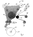
- Fig. 1 is a schematic of a production apparatus 10 embodying this invention.
- buff tapes are produced according to this invention by slitting a mother tape 20 longitudinally into a plurality of strips and by winding up these slit stripes.
- the mother tape 20 is basically of the same structure as the target buff tapes 25 to be produced, having a backing film 25b of a suitable material such as PET with a suitable thickness and coated with abrading particles such as aluminum oxide particles of a desired size such as 0.1-5.0 ⁇ m mixed in a urethane binder and dried to form a polishing layer 25a, different from the target buff tapes to be produced essentially in that it is much wider.
- the mother tape 20 is typically produced and provided in the form of a roll, or a web 22, typically having a width of 100mm to 1000mm and a length of 100m to 1000m, and is mounted to a feed roller 23, from which it is unwound and fed to a slitting device 30.
- the slitting device 30 may be of a conventionally known kind, for example, comprising a male knife 34 and a female knife 32 which engage with respect to each other and between which the mother tape 20 unwound from the web 22 is fed, the peripheral speed of the male knife 34 being 1.01-1.20 times greater than that of the female knife 32, for example, such that the mother tape 20 fed in between is slit thereby into a plurality of buff tapes 25 each with a specified width, say, in a typical range of 0.25 to 1.5 inches.
- the buff tapes 25, into which the mother tape 20 is thus slit longitudinally by means of the slitting device 30, are individually wound up around take-up rollers 28. Although two separate rollers 28 are shown in Fig. 1 for clearly showing that a plurality of buffer tapes 25 are individually being produced, the produced plurality of buff tapes 25 may be adapted to be wound up around a single roller to be taken up.
- a guide roller 40 with a polished steel surface is provided between the slitting device 30 and the take-up rollers 28 for guiding the slit buff tapes 25 from the slitting device 30 to the take-up rollers 28 by contacting the surface of the tapes coated with the particles.
- An AC motor 43 with a controller is provided for driving the slitting device 30, the guide roller 40 and the take-up roller 28 through interconnecting means such as a series of gears, brakes and timing belts (not shown), corresponding to the feed speed of the mother tape 20 to the slitting device 30.
- interconnecting means such as a series of gears, brakes and timing belts (not shown), corresponding to the feed speed of the mother tape 20 to the slitting device 30.
- Such a mechanism for controlling the feed speed is well known and is not intended to limit the scope of the invention.
- a compression roller 50 having a compressible peripheral surface with hardness of Shore A 50-70 Durometers is provided proximally to the portion of the surface of the guide roller 40 where the buff tapes 25 are in contact.
- a mechanism such as comprising pneumatic cylinders 52 along with a compressed air supply valve 53, is provided for moving the compression roller 50 towards the guide roller 40 such that a specified pressure may be applied as shown in Fig. 3 , and also away from the guide roller 40 to a retracted position as shown in Fig. 1 .
- a wiping tape 45 of a material such as a clean-room approved wiping cloth of polyester or nylon commonly used as a consumable product for direct or indirect contact use with a hard disk substrate surface is unwound from a supply roller 46, threaded around the compression roller 50 where it contacts the guide roller 40 and rewound by a take-up roller 47 such that, as the compression roller 50 is moved towards the guiding roller by the operation of the pneumatic cylinders 52 serving as its moving mechanism, the wiping tape 45 contacts the buff tapes 25 on the side of their backing film 25b.
- the wiping tape 45 is pressed onto the buff tapes 25 between the guide roller 40 and the compression roller 50 on the downstream side of the slitting device 30.
- the wiping tape 45 contacts the buff tapes 25 across the entire width and from the side of the backing film 25b because experiments have shown that the loose particles to be removed according to this invention are mostly attracted to the PET material of the backing film 25b due to the electrostatic charge of the buff tapes 25.
- the wiping tape 45 is advanced over the contacting surface of the compression roller 50 in the direction opposite to the motion of the buff tapes 25 by being unwound from the supply roller 46 and rewound around the take-up roller 47 at a specified supply rate.
- This supply rate is optimally determined according to other operational conditions such as the feed speed of the mother tape 20 and the compressive pressure between the guide roller 40 and the compression roller 50.
- the feed speed of the mother tape 20 should be greater than 10m/min from the point of view of the minimally acceptable productivity and should preferably be less than 30m/min from the point of view of the minimally acceptable winding quality for buff tapes 25 with a width of 1.375 inches.
- Table 1 shows some representative examples of preferred combination of the supply rate of the wiping tape 45 and the compressive pressure between the guide roller 40 and the compression roller 50 in the case of a compression roller with surface hardness of Shore A 50-70 Durometers for collecting debris particles of size of 0.3 to 5.0 ⁇ m on a 1 mil-PET backing film.
- Table 1 Feed speed of mother tape Supply rate of wiping tape Compressive pressure between guide roller and compression roller (kg/cm 2 ) 10 m/min 15 mm/min 2 kg/cm 2 15 m/min 22.5 mm/min 1.75 kg/cm 2 20 m/min 30 mm/min 1.5 kg/cm 2 25 m/min 37.5 mm/min 1.25 kg/cm 2 30 m/min 45 mm/min 1 kg/cm 2
Landscapes
- Engineering & Computer Science (AREA)
- Mechanical Engineering (AREA)
- Life Sciences & Earth Sciences (AREA)
- Forests & Forestry (AREA)
- Manufacturing Of Magnetic Record Carriers (AREA)
- Finish Polishing, Edge Sharpening, And Grinding By Specific Grinding Devices (AREA)
- Details Of Cutting Devices (AREA)
Abstract
Description
- This invention relates to an apparatus for and a method of producing buff tapes as per the preamble of
claims 1 and 10 respectively, for smoothing the surface of a magnetic disk substrate and more particularly to an apparatus and method for removing small loose debris particles of 0.3µm - 5µm in size when such buff tapes are produced from a mother tape by slitting it longitudinally. - An example of such an apparatus and of such a method is disclosed by
JP 63-047 069 - A magnetic disk substrate is generally produced by forming layers of metal and magnetic coatings on an aluminum or glass substrate and finally forming a layer of carbon and a lubricating protective over-coating. A surface smoothing process is carried out by using a buff tape (or polishing tape) to remove the abnormal protrusions which are inevitably present as described, for example, in
Japanese Patent Publication Tokko 2-10486 - Examples of prior art methods for removing such unwanted loose debris particles from buff tapes after obtained by slitting a much wider mother tape include the use of a tacky roller to force the loose particles to get stuck on its surface but the tacky roller material such as including silicon and/or urethane is commonly rejected in the list of materials that may be used or make contact with consumable products for hard disk substrate manufacturing. Another prior art method includes a wiping cloth and a vacuum device to suck up and trap the loose particles in the cloth material but the action of the wiping cloth and the vacuum causes the winding of the rolls to become uneven, loose and/or shifted. Also, the vacuum in a clean room environment upsets the laminar flow of the clean air and effectively causes debris and other particulates to enter the work area.
-
JP 63-047069 -
JP 63-214911 - It is therefore an object of this invention to provide an apparatus for and a method of producing buff tapes by simultaneously slitting a mother tape and effectively removing small debris particles in the range of 0.3µm to 5µm in size such that the produced buff tapes can be wound up properly without becoming uneven or shifted. According to a first aspect of the present invention there is provided an apparatus for producing buff tapes, as per claim 1.
- According to a second aspect of the present invention there is provided a method of producing buff tapes, as per
claim 10. - In the above, the slitting device may be a device of a know kind such as making use of a male knife and a female knife which rotate with respect to each other and thereby slit the mother tape passed in between. The mother tape is fed to the slitting device at a specified feed speed by a feeding means of a known kind such as a AC motor with a controller, compressing means of a known kind including pneumatic cylinders and a compressed air supply valve is provided for compressing the compression roller against the guide roller with a specified force with the wiping tape and the buff tapes in between, and the wiping tape is advanced in a direction opposite to the motion of the buffer tape by a wiping mechanism that may include a supplying roller and a take-up roller. The speed of the wiping tape is preferably specified according to the feed speed of the mother tape and the compressive pressure between the guide roller and the compression roller for achieving a desired efficiency.
- Since experiments have shown that debris particles that are generated by the slitting device tend to be attracted to the PET material of the backing film, the wiping tapes is contacted to the buff tapes from the side of their backing film.
-
-
Fig. 1 is a schematic drawing of a production apparatus embodying this invention for buff tapes when the wiping tape is not pressed against the buff tapes. -
Fig. 2 is a sectional view of a portion of the production apparatus ofFig. 1 including the guide roller and the compression roller with the mechanism for moving the compression roller towards and away from the guide roller. -
Fig. 3 is a schematic drawing of a portion of the production apparatus ofFig. 1 when the wiping tape is pressed against the buff tape through the motion of the compression roller. -
Fig. 1 is a schematic of aproduction apparatus 10 embodying this invention. Explained in most basic terms, buff tapes are produced according to this invention by slitting amother tape 20 longitudinally into a plurality of strips and by winding up these slit stripes. Themother tape 20 is basically of the same structure as thetarget buff tapes 25 to be produced, having abacking film 25b of a suitable material such as PET with a suitable thickness and coated with abrading particles such as aluminum oxide particles of a desired size such as 0.1-5.0µm mixed in a urethane binder and dried to form a polishing layer 25a, different from the target buff tapes to be produced essentially in that it is much wider. Themother tape 20 is typically produced and provided in the form of a roll, or aweb 22, typically having a width of 100mm to 1000mm and a length of 100m to 1000m, and is mounted to afeed roller 23, from which it is unwound and fed to aslitting device 30. - The
slitting device 30 may be of a conventionally known kind, for example, comprising a male knife 34 and afemale knife 32 which engage with respect to each other and between which the mother tape 20 unwound from theweb 22 is fed, the peripheral speed of the male knife 34 being 1.01-1.20 times greater than that of thefemale knife 32, for example, such that themother tape 20 fed in between is slit thereby into a plurality ofbuff tapes 25 each with a specified width, say, in a typical range of 0.25 to 1.5 inches. Thebuff tapes 25, into which themother tape 20 is thus slit longitudinally by means of theslitting device 30, are individually wound up around take-up rollers 28. Although twoseparate rollers 28 are shown inFig. 1 for clearly showing that a plurality ofbuffer tapes 25 are individually being produced, the produced plurality ofbuff tapes 25 may be adapted to be wound up around a single roller to be taken up. - A
guide roller 40 with a polished steel surface is provided between theslitting device 30 and the take-up rollers 28 for guiding theslit buff tapes 25 from theslitting device 30 to the take-up rollers 28 by contacting the surface of the tapes coated with the particles. AnAC motor 43 with a controller is provided for driving theslitting device 30, theguide roller 40 and the take-up roller 28 through interconnecting means such as a series of gears, brakes and timing belts (not shown), corresponding to the feed speed of themother tape 20 to theslitting device 30. Such a mechanism for controlling the feed speed is well known and is not intended to limit the scope of the invention. - As shown both in
Figs. 1 and2 , acompression roller 50 having a compressible peripheral surface with hardness of Shore A 50-70 Durometers is provided proximally to the portion of the surface of theguide roller 40 where thebuff tapes 25 are in contact. A mechanism, such as comprisingpneumatic cylinders 52 along with a compressedair supply valve 53, is provided for moving thecompression roller 50 towards theguide roller 40 such that a specified pressure may be applied as shown inFig. 3 , and also away from theguide roller 40 to a retracted position as shown inFig. 1 . - A
wiping tape 45 of a material such as a clean-room approved wiping cloth of polyester or nylon commonly used as a consumable product for direct or indirect contact use with a hard disk substrate surface is unwound from a supply roller 46, threaded around thecompression roller 50 where it contacts theguide roller 40 and rewound by a take-up roller 47 such that, as thecompression roller 50 is moved towards the guiding roller by the operation of thepneumatic cylinders 52 serving as its moving mechanism, thewiping tape 45 contacts thebuff tapes 25 on the side of theirbacking film 25b. - A method of using such an apparatus embodying this invention will be described next. As the controller for the
AC motor 43 is operated, themother tape 20 is fed to theslitting device 30 and thebuff tapes 25 thereby slit are individually wound up around the take-up rollers 28 at a specified feed speed. The male knife 34 and thefemale knife 32 of theslitting device 30 are each rotated at a conveniently specified rate as will be explained more in detail below. - As the
mother tape 20 is split into thebuff tapes 25, many loose debris particles are generated which are harmful and hence should be removed, as explained above. For this purpose, thewiping tape 45 is pressed onto thebuff tapes 25 between theguide roller 40 and thecompression roller 50 on the downstream side of theslitting device 30. Thewiping tape 45 contacts thebuff tapes 25 across the entire width and from the side of thebacking film 25b because experiments have shown that the loose particles to be removed according to this invention are mostly attracted to the PET material of thebacking film 25b due to the electrostatic charge of thebuff tapes 25. - As the compressive pressure with which the
compression roller 50 is pressed against theguide roller 40 with thebuff tapes 25 and thewiping tape 45 contacting each other and sandwiched therebetween by means of thepneumatic cylinders 52 and the compressedair supply valve 53, thewiping tape 45 is advanced over the contacting surface of thecompression roller 50 in the direction opposite to the motion of thebuff tapes 25 by being unwound from the supply roller 46 and rewound around the take-up roller 47 at a specified supply rate. This supply rate is optimally determined according to other operational conditions such as the feed speed of themother tape 20 and the compressive pressure between theguide roller 40 and thecompression roller 50. - These operational parameters should be carefully selected also for the purpose of effectively winding up the
buff tapes 25 around the take-up rollers 28. The feed speed of themother tape 20 should be greater than 10m/min from the point of view of the minimally acceptable productivity and should preferably be less than 30m/min from the point of view of the minimally acceptable winding quality forbuff tapes 25 with a width of 1.375 inches. For feed speeds between these minimum and maximum value, Table 1 shows some representative examples of preferred combination of the supply rate of thewiping tape 45 and the compressive pressure between theguide roller 40 and thecompression roller 50 in the case of a compression roller with surface hardness of Shore A 50-70 Durometers for collecting debris particles of size of 0.3 to 5.0µm on a 1 mil-PET backing film.Table 1 Feed speed of mother tape Supply rate of wiping tape Compressive pressure between guide roller and compression roller (kg/cm2) 10 m/min 15 mm/min 2 kg/cm2 15 m/min 22.5 mm/min 1.75 kg/cm2 20 m/ min 30 mm/min 1.5 kg/cm2 25 m/min 37.5 mm/min 1.25 kg/cm2 30 m/ min 45 mm/min 1 kg/cm2 - It is to be reminded, however, that these combinations are merely illustrative examples and not intended to limit the scope of the invention. Experiments have shown that a reduction of loose particles by 50% to 80% could be achieved by a method of this invention.
Claims (15)
- An apparatus for producing buff tapes (25), said apparatus comprising:a slitting device (32, 34) for receiving a mother tape (20) and slitting said received mother tape (20) longitudinally to thereby produce a plurality of buff tapes (25);take-up rollers (28) for individually taking up said buff tapes (25);a guide roller (40) for guiding said buff tapes (25) from said slitting device (32, 34) to said take-up rollers (28);the apparatus characterised by:a compression roller (50) positioned proximally to a portion of the surface of the guide roller (40) where the buff tapes (25) are in contact, the compression roller (50) configured to compress the buff tapes (25) onto said surface of the guide roller (40); anda wiping tape (45) that contacts said buff tapes (25) between said guide roller (40) and said compression roller (50) and serves to thereby remove debris particles from said buff tapes (25).
- The apparatus of claim 1 further comprising compressing means for compressing said compression roller (50) against said guide roller (40), with a specified force with said wiping tape (45) and said buff tapes (25) in between.
- The apparatus of claim 1 or claim 2 further comprising feeding means for feeding said mother tape (20) to said slitting device (32, 34) at a specified feed speed.
- The apparatus of any of claims 1 to 3 further comprising a wiping mechanism for causing said wiping tape (45) to advance at a specified rate.
- The apparatus of claim 4 wherein said wiping mechanism includes a pair of rollers (46, 47) for unwinding and rewinding said wiping tape (45) while causing said wiping tape (45) to advance at said specified rate.
- The apparatus of claim 4 or claim 5 further comprising feeding means for feeding said mother tape (20) to said slitting device (32, 34), at a specified feed speed, wherein said specified rate is determined from said feed speed and the pressure between said guide roller (40) and said compression roller (50).
- The apparatus of any preceding claim wherein said mother tape (20) comprises a backing film (25b) coated with abrading particles of 0.1-5.0µm in size.
- The apparatus of claim 7 wherein said wiping tape (45) contacts said backing film (25b) between said guide roller (40) and said compression roller (50).
- The apparatus of any preceding claim wherein said compression roller (50) has a surface hardness of Shore A 50-70 durometers.
- A method of producing buff tapes (25), said method comprising the steps of:feeding a mother tape (20) having backing film (25b) coated with abrading particles to a slitting device (32, 34) at a specified feed speed;using said slitting device (32, 34) to slit said mother tape (20) longitudinally to obtain a plurality of buff tapes (25);taking up said slit buff tapes (25) individually around take-up rollers (28);providing a guide roller (40) between said take-up rollers (28) and said slitting device (32, 34) for guiding said buff tapes (25) from said slitting device (32, 34) towards said take-up rollers (28);said method characterised by:compressing said buff tapes (25) against a portion of the surface of said guide roller (40) where the buff tapes (25) are in contact using a compression roller (50) positioned proximally to the portion of the surface of the guide roller (40); andproviding a wiping tape (45) compressed against said buff tapes (25) between said surface of the guide roller (40) and said compression roller (50) to thereby remove debris particles from said buff tapes (25).
- The method of claim 10 further comprising the step of advancing said wiping tape (45) at a specified rate using a wiping mechanism.
- The method of claims 10 or 11 wherein said mother tape (20) comprises a backing film (25b) coated with abrading particles of 0.1-5.0µm in size.
- The method of claim 12 wherein said wiping tape (45) contacts said backing film (25b) between said surface of the guide roller (40) and said compression roller (50).
- The method of any one of claims 10 to 13 wherein a feed speed of the mother tape (20) is 10 m/min - 30 m/min, an advancing rate of the wiping tape (45) is 15 mm/mm - 45 mm/min and said compression roller (50) is compressed against said surface of the guide roller (40) with a pressure of 1 kg/cm2 - 2 kg/cm2.
- The method as claimed in claim 14 wherein the compression roller (50) comprises a surface hardness of Shore A 50-70 durometers configured to remove 50% to 80% of loose particles of 0.3µm to 5µm from said buff tapes (25) by said wiping tape (45).
Applications Claiming Priority (1)
| Application Number | Priority Date | Filing Date | Title |
|---|---|---|---|
| US11/190,669 US20070023560A1 (en) | 2005-07-26 | 2005-07-26 | Apparatus for and method of producing buff tapes |
Publications (3)
| Publication Number | Publication Date |
|---|---|
| EP1747850A2 EP1747850A2 (en) | 2007-01-31 |
| EP1747850A3 EP1747850A3 (en) | 2007-08-08 |
| EP1747850B1 true EP1747850B1 (en) | 2009-03-25 |
Family
ID=37192386
Family Applications (1)
| Application Number | Title | Priority Date | Filing Date |
|---|---|---|---|
| EP06253873A Not-in-force EP1747850B1 (en) | 2005-07-26 | 2006-07-24 | Apparatus for and method of producing buff tapes |
Country Status (5)
| Country | Link |
|---|---|
| US (1) | US20070023560A1 (en) |
| EP (1) | EP1747850B1 (en) |
| JP (1) | JP2007050503A (en) |
| AT (1) | ATE426486T1 (en) |
| DE (1) | DE602006005866D1 (en) |
Families Citing this family (4)
| Publication number | Priority date | Publication date | Assignee | Title |
|---|---|---|---|---|
| JP4625517B2 (en) | 2008-10-27 | 2011-02-02 | 富士フイルム株式会社 | Three-dimensional display device, method and program |
| JP5967383B2 (en) * | 2014-03-18 | 2016-08-10 | コニカミノルタ株式会社 | Post-processing apparatus and image forming system |
| CN114405936A (en) * | 2021-12-01 | 2022-04-29 | 西安泰金工业电化学技术有限公司 | A dust collector for ultra-thin copper foil surface |
| CN119750296B (en) * | 2025-03-10 | 2025-06-03 | 四川省科学城久信科技有限公司 | Automatic wave cutting and trimming device for film capacitor electrode foil |
Family Cites Families (19)
| Publication number | Priority date | Publication date | Assignee | Title |
|---|---|---|---|---|
| JPH0710504B2 (en) | 1986-08-08 | 1995-02-08 | 富士写真フイルム株式会社 | Polishing tape manufacturing method |
| JPS63214911A (en) | 1987-03-03 | 1988-09-07 | Fuji Photo Film Co Ltd | Magnetic tape cleaning device |
| JP3218617B2 (en) * | 1990-07-02 | 2001-10-15 | ソニー株式会社 | Calendar roll cleaning device |
| JPH06773A (en) * | 1992-06-22 | 1994-01-11 | Fuji Photo Film Co Ltd | Manufacture of abrasive tape |
| US5474248A (en) * | 1993-08-16 | 1995-12-12 | Product Search, Inc. | Slitter/rewinder machine |
| US5611826A (en) * | 1994-03-01 | 1997-03-18 | Fuji Photo Film Co., Ltd. | Abrasive tape |
| FR2722127B1 (en) * | 1994-07-06 | 1996-08-14 | Kodak Pathe | METHOD AND DEVICE FOR CUTTING PHOTOGRAPHIC PRODUCTS INTO BANDS |
| JPH0985631A (en) * | 1995-09-28 | 1997-03-31 | Fuji Photo Film Co Ltd | Polishing body |
| US5991954A (en) * | 1996-02-05 | 1999-11-30 | Fuji Photo Film Co., Ltd. | Apparatus for cleaning photo film |
| US5930857A (en) * | 1997-10-14 | 1999-08-03 | Eastman Kodak Company | Apparatus for cleaning a surface of a moving web |
| US6036787A (en) * | 1998-07-13 | 2000-03-14 | Dek Printing Machines, Ltd. | Stencil cleaning apparatus |
| JP3640291B2 (en) * | 1998-12-07 | 2005-04-20 | 富士写真フイルム株式会社 | Magnetic recording medium manufacturing method and manufacturing apparatus thereof |
| FI105463B (en) * | 1999-01-22 | 2000-08-31 | Valmet Corp | Method and apparatus for rolling a paper web |
| US6378154B1 (en) * | 1999-11-18 | 2002-04-30 | Seratek, Llc | Web cleaning system |
| JP3728406B2 (en) * | 2000-06-15 | 2005-12-21 | シャープ株式会社 | Substrate cleaning device |
| US6505372B1 (en) * | 2001-02-27 | 2003-01-14 | Amphenol Corporation | Wire cleaning apparatus and method |
| ITBG20020015A1 (en) * | 2002-04-23 | 2003-10-23 | Tgc Srl | APPARATUS FOR THE PREPARATION AND / OR REGENERATION OF DETERGENT COILS IN FABRIC FOR THE CLEANING OF PRINT CYLINDERS OR PREC EQUIVALENT |
| JP2005339593A (en) * | 2004-05-24 | 2005-12-08 | Fuji Photo Film Co Ltd | Magnetic tape and its manufacturing method |
| US20060153977A1 (en) * | 2005-01-12 | 2006-07-13 | Fuji Photo Film Co., Ltd. | Magnetic tape, and manufacturing method and winding apparatus therefor |
-
2005
- 2005-07-26 US US11/190,669 patent/US20070023560A1/en not_active Abandoned
-
2006
- 2006-07-24 AT AT06253873T patent/ATE426486T1/en not_active IP Right Cessation
- 2006-07-24 EP EP06253873A patent/EP1747850B1/en not_active Not-in-force
- 2006-07-24 DE DE602006005866T patent/DE602006005866D1/en not_active Expired - Fee Related
- 2006-07-26 JP JP2006202868A patent/JP2007050503A/en active Pending
Also Published As
| Publication number | Publication date |
|---|---|
| EP1747850A2 (en) | 2007-01-31 |
| ATE426486T1 (en) | 2009-04-15 |
| EP1747850A3 (en) | 2007-08-08 |
| JP2007050503A (en) | 2007-03-01 |
| DE602006005866D1 (en) | 2009-05-07 |
| US20070023560A1 (en) | 2007-02-01 |
Similar Documents
| Publication | Publication Date | Title |
|---|---|---|
| KR101442262B1 (en) | System and method for polishing surface of tape-like metal base material | |
| JPS59156507A (en) | Roll grinding equipment | |
| KR20150089803A (en) | Electrode Notching Apparatus for Secondary Battery | |
| US6001004A (en) | Panel sanding machine with automatic changing and cleaning of the abrasive belt | |
| KR100840120B1 (en) | Continuous processing method and continuous processing device for slitting cutting surface burring and protective film formation | |
| US20070023560A1 (en) | Apparatus for and method of producing buff tapes | |
| KR101440734B1 (en) | A method of processing thin strips using a blast machine | |
| CN114074854B (en) | Using method of clothing trademark laser coil stock marking machine with liquid waste removal function | |
| JP2009297844A (en) | Polishing device and polishing method | |
| US7131185B2 (en) | Method of manufacturing magnetic recording medium | |
| CN212697859U (en) | Mask sheet making machine with built-in nose bridge strip | |
| CN215965602U (en) | Finishing device with scraping milling and dust removing functions | |
| KR200332891Y1 (en) | Sheet laminating Apparatus for manufacturing nail file | |
| JPH08243907A (en) | Manufacture of hairline finishing metallic belt and device therefor | |
| CN223339677U (en) | Automatic slitting type casting machine | |
| US6811472B2 (en) | Inline lapping of magnetic tape | |
| DE29706768U1 (en) | Device for processing magnetic tapes | |
| JP4857762B2 (en) | Method and apparatus for preventing surface defect of metal strip | |
| JP4396329B2 (en) | Band connection device | |
| SU1602702A1 (en) | Method of belt grinding of bodies of rotation | |
| US20020118488A1 (en) | Magnetic recording medium and method of smoothing surface of magnetic recording medium | |
| JPH06269809A (en) | High gloss stainless cold rolled steel sheet manufacturing method and skin pass roll polishing apparatus | |
| JP2004276147A (en) | Grinding device and manufacturing method of magnetic record medium using it | |
| CN114012657A (en) | Laminating equipment | |
| JPH07105538A (en) | Edge finishing method for magnetic tape and its edge finishing device |
Legal Events
| Date | Code | Title | Description |
|---|---|---|---|
| PUAI | Public reference made under article 153(3) epc to a published international application that has entered the european phase |
Free format text: ORIGINAL CODE: 0009012 |
|
| AK | Designated contracting states |
Kind code of ref document: A2 Designated state(s): AT BE BG CH CY CZ DE DK EE ES FI FR GB GR HU IE IS IT LI LT LU LV MC NL PL PT RO SE SI SK TR |
|
| AX | Request for extension of the european patent |
Extension state: AL BA HR MK YU |
|
| RIN1 | Information on inventor provided before grant (corrected) |
Inventor name: TIMBANG, ALVIN Inventor name: KODAKA, ICHIRO Inventor name: VAN BANG, VUONG |
|
| PUAL | Search report despatched |
Free format text: ORIGINAL CODE: 0009013 |
|
| AK | Designated contracting states |
Kind code of ref document: A3 Designated state(s): AT BE BG CH CY CZ DE DK EE ES FI FR GB GR HU IE IS IT LI LT LU LV MC NL PL PT RO SE SI SK TR |
|
| AX | Request for extension of the european patent |
Extension state: AL BA HR MK YU |
|
| RIN1 | Information on inventor provided before grant (corrected) |
Inventor name: VAN BANG, VUONGMIPOX INTERNATIONAL CORP Inventor name: KODAKA, ICHIRO Inventor name: TIMBANG, ALVIN |
|
| 17P | Request for examination filed |
Effective date: 20080111 |
|
| 17Q | First examination report despatched |
Effective date: 20080311 |
|
| AKX | Designation fees paid |
Designated state(s): AT BE BG CH CY CZ DE DK EE ES FI FR GB GR HU IE IS IT LI LT LU LV MC NL PL PT RO SE SI SK TR |
|
| GRAP | Despatch of communication of intention to grant a patent |
Free format text: ORIGINAL CODE: EPIDOSNIGR1 |
|
| GRAS | Grant fee paid |
Free format text: ORIGINAL CODE: EPIDOSNIGR3 |
|
| GRAA | (expected) grant |
Free format text: ORIGINAL CODE: 0009210 |
|
| AK | Designated contracting states |
Kind code of ref document: B1 Designated state(s): AT BE BG CH CY CZ DE DK EE ES FI FR GB GR HU IE IS IT LI LT LU LV MC NL PL PT RO SE SI SK TR |
|
| REG | Reference to a national code |
Ref country code: GB Ref legal event code: FG4D |
|
| REG | Reference to a national code |
Ref country code: CH Ref legal event code: EP |
|
| REG | Reference to a national code |
Ref country code: IE Ref legal event code: FG4D |
|
| REF | Corresponds to: |
Ref document number: 602006005866 Country of ref document: DE Date of ref document: 20090507 Kind code of ref document: P |
|
| PG25 | Lapsed in a contracting state [announced via postgrant information from national office to epo] |
Ref country code: FI Free format text: LAPSE BECAUSE OF FAILURE TO SUBMIT A TRANSLATION OF THE DESCRIPTION OR TO PAY THE FEE WITHIN THE PRESCRIBED TIME-LIMIT Effective date: 20090325 Ref country code: LT Free format text: LAPSE BECAUSE OF FAILURE TO SUBMIT A TRANSLATION OF THE DESCRIPTION OR TO PAY THE FEE WITHIN THE PRESCRIBED TIME-LIMIT Effective date: 20090325 Ref country code: SI Free format text: LAPSE BECAUSE OF FAILURE TO SUBMIT A TRANSLATION OF THE DESCRIPTION OR TO PAY THE FEE WITHIN THE PRESCRIBED TIME-LIMIT Effective date: 20090325 |
|
| PG25 | Lapsed in a contracting state [announced via postgrant information from national office to epo] |
Ref country code: LV Free format text: LAPSE BECAUSE OF FAILURE TO SUBMIT A TRANSLATION OF THE DESCRIPTION OR TO PAY THE FEE WITHIN THE PRESCRIBED TIME-LIMIT Effective date: 20090325 Ref country code: SE Free format text: LAPSE BECAUSE OF FAILURE TO SUBMIT A TRANSLATION OF THE DESCRIPTION OR TO PAY THE FEE WITHIN THE PRESCRIBED TIME-LIMIT Effective date: 20090625 Ref country code: PL Free format text: LAPSE BECAUSE OF FAILURE TO SUBMIT A TRANSLATION OF THE DESCRIPTION OR TO PAY THE FEE WITHIN THE PRESCRIBED TIME-LIMIT Effective date: 20090325 Ref country code: AT Free format text: LAPSE BECAUSE OF FAILURE TO SUBMIT A TRANSLATION OF THE DESCRIPTION OR TO PAY THE FEE WITHIN THE PRESCRIBED TIME-LIMIT Effective date: 20090325 |
|
| NLV1 | Nl: lapsed or annulled due to failure to fulfill the requirements of art. 29p and 29m of the patents act | ||
| PG25 | Lapsed in a contracting state [announced via postgrant information from national office to epo] |
Ref country code: BE Free format text: LAPSE BECAUSE OF FAILURE TO SUBMIT A TRANSLATION OF THE DESCRIPTION OR TO PAY THE FEE WITHIN THE PRESCRIBED TIME-LIMIT Effective date: 20090325 |
|
| PG25 | Lapsed in a contracting state [announced via postgrant information from national office to epo] |
Ref country code: CZ Free format text: LAPSE BECAUSE OF FAILURE TO SUBMIT A TRANSLATION OF THE DESCRIPTION OR TO PAY THE FEE WITHIN THE PRESCRIBED TIME-LIMIT Effective date: 20090325 Ref country code: PT Free format text: LAPSE BECAUSE OF FAILURE TO SUBMIT A TRANSLATION OF THE DESCRIPTION OR TO PAY THE FEE WITHIN THE PRESCRIBED TIME-LIMIT Effective date: 20090901 Ref country code: ES Free format text: LAPSE BECAUSE OF FAILURE TO SUBMIT A TRANSLATION OF THE DESCRIPTION OR TO PAY THE FEE WITHIN THE PRESCRIBED TIME-LIMIT Effective date: 20090706 Ref country code: EE Free format text: LAPSE BECAUSE OF FAILURE TO SUBMIT A TRANSLATION OF THE DESCRIPTION OR TO PAY THE FEE WITHIN THE PRESCRIBED TIME-LIMIT Effective date: 20090325 |
|
| PG25 | Lapsed in a contracting state [announced via postgrant information from national office to epo] |
Ref country code: RO Free format text: LAPSE BECAUSE OF FAILURE TO SUBMIT A TRANSLATION OF THE DESCRIPTION OR TO PAY THE FEE WITHIN THE PRESCRIBED TIME-LIMIT Effective date: 20090325 Ref country code: SK Free format text: LAPSE BECAUSE OF FAILURE TO SUBMIT A TRANSLATION OF THE DESCRIPTION OR TO PAY THE FEE WITHIN THE PRESCRIBED TIME-LIMIT Effective date: 20090325 Ref country code: IS Free format text: LAPSE BECAUSE OF FAILURE TO SUBMIT A TRANSLATION OF THE DESCRIPTION OR TO PAY THE FEE WITHIN THE PRESCRIBED TIME-LIMIT Effective date: 20090725 Ref country code: NL Free format text: LAPSE BECAUSE OF FAILURE TO SUBMIT A TRANSLATION OF THE DESCRIPTION OR TO PAY THE FEE WITHIN THE PRESCRIBED TIME-LIMIT Effective date: 20090325 |
|
| PG25 | Lapsed in a contracting state [announced via postgrant information from national office to epo] |
Ref country code: BG Free format text: LAPSE BECAUSE OF FAILURE TO SUBMIT A TRANSLATION OF THE DESCRIPTION OR TO PAY THE FEE WITHIN THE PRESCRIBED TIME-LIMIT Effective date: 20090625 Ref country code: DK Free format text: LAPSE BECAUSE OF FAILURE TO SUBMIT A TRANSLATION OF THE DESCRIPTION OR TO PAY THE FEE WITHIN THE PRESCRIBED TIME-LIMIT Effective date: 20090325 |
|
| PLBE | No opposition filed within time limit |
Free format text: ORIGINAL CODE: 0009261 |
|
| STAA | Information on the status of an ep patent application or granted ep patent |
Free format text: STATUS: NO OPPOSITION FILED WITHIN TIME LIMIT |
|
| PG25 | Lapsed in a contracting state [announced via postgrant information from national office to epo] |
Ref country code: MC Free format text: LAPSE BECAUSE OF NON-PAYMENT OF DUE FEES Effective date: 20090731 |
|
| 26N | No opposition filed |
Effective date: 20091229 |
|
| PG25 | Lapsed in a contracting state [announced via postgrant information from national office to epo] |
Ref country code: DE Free format text: LAPSE BECAUSE OF NON-PAYMENT OF DUE FEES Effective date: 20100202 |
|
| PG25 | Lapsed in a contracting state [announced via postgrant information from national office to epo] |
Ref country code: IE Free format text: LAPSE BECAUSE OF NON-PAYMENT OF DUE FEES Effective date: 20090724 |
|
| PG25 | Lapsed in a contracting state [announced via postgrant information from national office to epo] |
Ref country code: GR Free format text: LAPSE BECAUSE OF FAILURE TO SUBMIT A TRANSLATION OF THE DESCRIPTION OR TO PAY THE FEE WITHIN THE PRESCRIBED TIME-LIMIT Effective date: 20090626 |
|
| PGFP | Annual fee paid to national office [announced via postgrant information from national office to epo] |
Ref country code: FR Payment date: 20100805 Year of fee payment: 5 |
|
| REG | Reference to a national code |
Ref country code: CH Ref legal event code: PL |
|
| GBPC | Gb: european patent ceased through non-payment of renewal fee |
Effective date: 20100724 |
|
| PG25 | Lapsed in a contracting state [announced via postgrant information from national office to epo] |
Ref country code: IT Free format text: LAPSE BECAUSE OF FAILURE TO SUBMIT A TRANSLATION OF THE DESCRIPTION OR TO PAY THE FEE WITHIN THE PRESCRIBED TIME-LIMIT Effective date: 20090325 |
|
| PG25 | Lapsed in a contracting state [announced via postgrant information from national office to epo] |
Ref country code: CH Free format text: LAPSE BECAUSE OF NON-PAYMENT OF DUE FEES Effective date: 20100731 Ref country code: LI Free format text: LAPSE BECAUSE OF NON-PAYMENT OF DUE FEES Effective date: 20100731 Ref country code: LU Free format text: LAPSE BECAUSE OF NON-PAYMENT OF DUE FEES Effective date: 20090724 |
|
| PG25 | Lapsed in a contracting state [announced via postgrant information from national office to epo] |
Ref country code: HU Free format text: LAPSE BECAUSE OF FAILURE TO SUBMIT A TRANSLATION OF THE DESCRIPTION OR TO PAY THE FEE WITHIN THE PRESCRIBED TIME-LIMIT Effective date: 20090926 |
|
| PG25 | Lapsed in a contracting state [announced via postgrant information from national office to epo] |
Ref country code: GB Free format text: LAPSE BECAUSE OF NON-PAYMENT OF DUE FEES Effective date: 20100724 |
|
| PG25 | Lapsed in a contracting state [announced via postgrant information from national office to epo] |
Ref country code: TR Free format text: LAPSE BECAUSE OF FAILURE TO SUBMIT A TRANSLATION OF THE DESCRIPTION OR TO PAY THE FEE WITHIN THE PRESCRIBED TIME-LIMIT Effective date: 20090325 |
|
| PG25 | Lapsed in a contracting state [announced via postgrant information from national office to epo] |
Ref country code: CY Free format text: LAPSE BECAUSE OF FAILURE TO SUBMIT A TRANSLATION OF THE DESCRIPTION OR TO PAY THE FEE WITHIN THE PRESCRIBED TIME-LIMIT Effective date: 20090325 |
|
| REG | Reference to a national code |
Ref country code: FR Ref legal event code: ST Effective date: 20120330 |
|
| PG25 | Lapsed in a contracting state [announced via postgrant information from national office to epo] |
Ref country code: FR Free format text: LAPSE BECAUSE OF NON-PAYMENT OF DUE FEES Effective date: 20110801 |