EP1746823A1 - Light projection device - Google Patents
Light projection device Download PDFInfo
- Publication number
- EP1746823A1 EP1746823A1 EP06076394A EP06076394A EP1746823A1 EP 1746823 A1 EP1746823 A1 EP 1746823A1 EP 06076394 A EP06076394 A EP 06076394A EP 06076394 A EP06076394 A EP 06076394A EP 1746823 A1 EP1746823 A1 EP 1746823A1
- Authority
- EP
- European Patent Office
- Prior art keywords
- light
- projection device
- valve
- light valve
- light source
- Prior art date
- Legal status (The legal status is an assumption and is not a legal conclusion. Google has not performed a legal analysis and makes no representation as to the accuracy of the status listed.)
- Withdrawn
Links
Images
Classifications
-
- H—ELECTRICITY
- H04—ELECTRIC COMMUNICATION TECHNIQUE
- H04N—PICTORIAL COMMUNICATION, e.g. TELEVISION
- H04N5/00—Details of television systems
- H04N5/74—Projection arrangements for image reproduction, e.g. using eidophor
- H04N5/7416—Projection arrangements for image reproduction, e.g. using eidophor involving the use of a spatial light modulator, e.g. a light valve, controlled by a video signal
-
- H—ELECTRICITY
- H04—ELECTRIC COMMUNICATION TECHNIQUE
- H04N—PICTORIAL COMMUNICATION, e.g. TELEVISION
- H04N9/00—Details of colour television systems
- H04N9/12—Picture reproducers
- H04N9/31—Projection devices for colour picture display, e.g. using electronic spatial light modulators [ESLM]
- H04N9/3141—Constructional details thereof
- H04N9/315—Modulator illumination systems
- H04N9/3152—Modulator illumination systems for shaping the light beam
Definitions
- the present invention concerns a light projection device.
- Known light projection devices generally consist of a light source provided with one or more reflectors, one or more mirrors for collimating the light beam emitted by the light source, a light valve for processing the collimated light beam and a lens through which the processed light beam is projected.
- the light beam emitted by the light source is concentrated in a circular spot that is directed to the generally rectangular light valve in a way the entire light valve is equally covered by the light spot.
- a disadvantage of said known light projection devices is that the circular light spot has a transversal cross section that is larger than the surface of the light valve, resulting in a poor light yield since a part of the light emitted by the light source is directed next to the light valve.
- the goal of the present invention is to solve the above mentioned and other disadvantages.
- the present invention concerns a light projection device that at least comprises a light source and a light valve consisting of an array of light processing elements, wherein a lens unit is provided in between the light source and the concerned light valve.
- An advantage of the present invention is that said lens provided in between said light source and the concerned light valve allows to automatically adapt the area of transversal cross section of the light beam emitted by the light source.
- This adaptation of the area of the light valve being lit by the light source allows a user to project an image with an optimized light yield in the case the image to be projected is substantially circular or to equally lit the entire surface of the light valve in case the image to be projected is substantially rectangular.
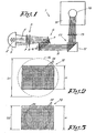
- Figure 1 schematically represents a light projection device 1 according to the invention, comprising a light source 2 that is provided with a curved reflector 3.
- Said light source 2 is preferably of a type emitting a stable light, such as the known low pressure metal halide lamps.
- the reflector 3 reflects the light emitted by the light valve in a specific direction in order to create a strong light beam 4 wherein the majority of the light emitted by the light source 2 is concentrated.
- a lens unit 5 and, preferably, a mirror assembly 6 are provided in front of the light source 2, whereby said lens unit 5 preferably consists of an plurality of aligned lenses 7, 8 that can be mutually displaced in an axial direction.
- the mirror assembly 6 may consist of, for example, a mirror 9 and some separation elements 10, allowing to convert the light beam 4 emitted by the light source 2 into a collimated light beam 11.
- the light projection device 1 further comprises a light valve 12 and a lens 13, whereby the light valve 12 consists of an array of light processing elements 14 such as micro mirrors or liquid crystals.
- said light processing elements 14 can individually be switched between two positions, namely a position wherein the incoming light beam 11 is directed trough the lens 13 on a screen 15, and a position wherein the incoming light beam 11 is directed next to the lens 13, each light processing element 14 corresponding to a single pixel of an image 16 to be build.
- the lenses 7-8 of the lens unit 5 are spaced apart at a certain distance, such that the incoming light beam 4 of the mirror assembly 6 has a transversal cross section with a diameter D1 that is equal or larger than the length of a diagonal of the light valve.
- the incoming collimated light beam 11 covers the entire light valve 12, such that rectangular images 16 can be projected through the lens with an optimal resolution.
- the distance between the lenses 7 and 8 of the lens unit 5 can be adapted such that the transversal cross section of the light beam 11 has a diameter D2 that is substantially equal to the height H of the light valve 12.
- the lenses 7 and 8 can be placed at different mutual distances, thereby allowing to lit a part of the light valve ranging from a single point to the entire surface of that light valve.
- the lens unit 5 allows to change the focal point of the light beam 4 emitted by the light source 2, such that the diameter of the incoming light beam 11 on the light valve 12 can be varied between a value corresponding to the diagonal of the surface of one single light processing element 14 and a value that is equal to the diagonal of the light valve 12.
- the brightness of the image to be build increases when the surface of the light valve that is lit, decreases.
Landscapes
- Engineering & Computer Science (AREA)
- Multimedia (AREA)
- Signal Processing (AREA)
- Projection Apparatus (AREA)
- Non-Portable Lighting Devices Or Systems Thereof (AREA)
- Liquid Crystal (AREA)
Abstract
A light projection device at least comprising a light source and a light valve consisting of an array of light processing elements, wherein a lens unit is provided in between the light source and the concerned light valve.
Description
- The present invention concerns a light projection device.
- Known light projection devices generally consist of a light source provided with one or more reflectors, one or more mirrors for collimating the light beam emitted by the light source, a light valve for processing the collimated light beam and a lens through which the processed light beam is projected.
- As known, the light beam emitted by the light source is concentrated in a circular spot that is directed to the generally rectangular light valve in a way the entire light valve is equally covered by the light spot.
- A disadvantage of said known light projection devices is that the circular light spot has a transversal cross section that is larger than the surface of the light valve, resulting in a poor light yield since a part of the light emitted by the light source is directed next to the light valve.
- A solution for the above mentioned disadvantage to regulate the distance between the light source and the concerned mirror, so that the mirror is moved closer to the focal point of the light emitted by the light source and redirected by the concerned reflector.
- By doing so, the transversal cross section of the collimated light spot is diminished, so that said circular collimated light spot falls within the boundaries of the light valve, resulting in an optimized light yield.
- This known solution however has one important drawback, namely that a part of the light valve, in particular the corners, remain unlit, thereby rendering it impossible to build a rectangular image with a maximal resolution allowed by the light valve.
- The goal of the present invention is to solve the above mentioned and other disadvantages.
- Thereto the present invention concerns a light projection device that at least comprises a light source and a light valve consisting of an array of light processing elements, wherein a lens unit is provided in between the light source and the concerned light valve.
- An advantage of the present invention is that said lens provided in between said light source and the concerned light valve allows to automatically adapt the area of transversal cross section of the light beam emitted by the light source.
- This adaptation of the area of the light valve being lit by the light source allows a user to project an image with an optimized light yield in the case the image to be projected is substantially circular or to equally lit the entire surface of the light valve in case the image to be projected is substantially rectangular.
- In order to better explain the characteristics of the invention, the following embodiment of a light projection device according to the invention is described as an example only without being limitative in any way, with reference to the accompanying drawings, wherein:
- figure 1 schematically represents a light projection device according to the invention;
- figure 2 represents, on a larger scale, a view according to arrow F2 in figure 1;
- figure 3 represents a same view as figure 2, although in
- another stand of the light projection device.
- Figure 1 schematically represents a light projection device 1 according to the invention, comprising a light source 2 that is provided with a curved reflector 3.
- Said light source 2 is preferably of a type emitting a stable light, such as the known low pressure metal halide lamps.
- The reflector 3 reflects the light emitted by the light valve in a specific direction in order to create a strong light beam 4 wherein the majority of the light emitted by the light source 2 is concentrated.
- According to the invention, a
lens unit 5 and, preferably, amirror assembly 6 are provided in front of the light source 2, whereby saidlens unit 5 preferably consists of an plurality of aligned lenses 7, 8 that can be mutually displaced in an axial direction. - The
mirror assembly 6 may consist of, for example, a mirror 9 and someseparation elements 10, allowing to convert the light beam 4 emitted by the light source 2 into a collimated light beam 11. - The light projection device 1 further comprises a
light valve 12 and alens 13, whereby thelight valve 12 consists of an array oflight processing elements 14 such as micro mirrors or liquid crystals. - As known, said
light processing elements 14 can individually be switched between two positions, namely a position wherein the incoming light beam 11 is directed trough thelens 13 on ascreen 15, and a position wherein the incoming light beam 11 is directed next to thelens 13, eachlight processing element 14 corresponding to a single pixel of animage 16 to be build. - The use of the above described light projection device 1 according to the invention is easy and as follows.
- In a normal position, the lenses 7-8 of the
lens unit 5 are spaced apart at a certain distance, such that the incoming light beam 4 of themirror assembly 6 has a transversal cross section with a diameter D1 that is equal or larger than the length of a diagonal of the light valve. - In that case, the incoming collimated light beam 11, the cross section of which is shown in a dashed line in figure 2, covers the
entire light valve 12, such thatrectangular images 16 can be projected through the lens with an optimal resolution. - In the case the
image 16 to be projected is substantially circular, the distance between the lenses 7 and 8 of thelens unit 5 can be adapted such that the transversal cross section of the light beam 11 has a diameter D2 that is substantially equal to the height H of thelight valve 12. - In this last case, shown in figure 3, only a part of the
light valve 12 is lit by the light beam 11, such that only this part of thelight valve 12 can be used for image building. - It is clear that the last configuration allows to build
images 16 with an optimized light yield and thus an enhanced brightness. - Indeed, all the light of the light beam 11 is concentrated on the
light valve 12, which is not the case in the configuration wherein the light beam 11 has a diameter that is larger than the height H of thelight valve 12. - It is clear that the lenses 7 and 8 can be placed at different mutual distances, thereby allowing to lit a part of the light valve ranging from a single point to the entire surface of that light valve.
- In other words, the
lens unit 5 allows to change the focal point of the light beam 4 emitted by the light source 2, such that the diameter of the incoming light beam 11 on thelight valve 12 can be varied between a value corresponding to the diagonal of the surface of one singlelight processing element 14 and a value that is equal to the diagonal of thelight valve 12. - It is hereby remarked that the brightness of the image to be build increases when the surface of the light valve that is lit, decreases.
- The present invention is by no means limited to the above described embodiment given only as an example and represented in the accompanying drawings; on the contrary, such a light valve can be realized in all sorts of variants while still remaining within the scope of the present invention.
Claims (4)
- A light projection device at least comprising a light source (2) and a light valve (12) consisting of an array of light processing elements (14), characterized in that a lens unit (5) is provided in between the light source (2) and the concerned light valve (12).
- The light projection device according to claim 1, characterized in that the lens unit (5) consists of a plurality of aligned lenses (7-8) that can be mutually displaced in an axial direction.
- The light projection device according to claim 1, characterized in that it comprises a mirror assembly (6) in between the lens unit (5) and the concerned light valve (12).
- The light projection device according to claim 1, characterized in that the lens unit (5) allows to change the focal point of the light beam (4) emitted by the light source (2), such that the diameter of the incoming light beam (11) on the light valve (12) can be varied between a value that is equal to a diagonal of the light valve (12) and a value corresponding to the diagonal of a single light processing element (14) of the light valve (12).
Applications Claiming Priority (1)
| Application Number | Priority Date | Filing Date | Title |
|---|---|---|---|
| US11/183,264 US20070014021A1 (en) | 2005-07-18 | 2005-07-18 | Light projection device |
Publications (1)
| Publication Number | Publication Date |
|---|---|
| EP1746823A1 true EP1746823A1 (en) | 2007-01-24 |
Family
ID=37400999
Family Applications (1)
| Application Number | Title | Priority Date | Filing Date |
|---|---|---|---|
| EP06076394A Withdrawn EP1746823A1 (en) | 2005-07-18 | 2006-07-11 | Light projection device |
Country Status (3)
| Country | Link |
|---|---|
| US (1) | US20070014021A1 (en) |
| EP (1) | EP1746823A1 (en) |
| JP (1) | JP2007027118A (en) |
Cited By (2)
| Publication number | Priority date | Publication date | Assignee | Title |
|---|---|---|---|---|
| EP2402172A1 (en) | 2010-06-23 | 2012-01-04 | Flooring Industries Limited, SARL | Method for manufacturing coated panels |
| CN105759546A (en) * | 2015-01-07 | 2016-07-13 | 株式会社理光 | Image projection apparatus |
Families Citing this family (2)
| Publication number | Priority date | Publication date | Assignee | Title |
|---|---|---|---|---|
| JP2010107566A (en) * | 2008-10-28 | 2010-05-13 | Olympus Imaging Corp | Imaging apparatus |
| CN110161786B (en) * | 2018-02-12 | 2021-08-31 | 深圳富泰宏精密工业有限公司 | Light projection module, three-dimensional image sensing device and sensing method thereof |
Citations (3)
| Publication number | Priority date | Publication date | Assignee | Title |
|---|---|---|---|---|
| US20010015775A1 (en) * | 2000-02-18 | 2001-08-23 | Chikara Yamamoto | Illumination optical system and projection type display apparatus using the same |
| EP1220011A2 (en) * | 2000-12-28 | 2002-07-03 | Lg Electronics Inc. | Projector with polarization converter |
| EP1398973A2 (en) * | 2002-08-20 | 2004-03-17 | Seiko Epson Corporation | Image display device and projector |
Family Cites Families (2)
| Publication number | Priority date | Publication date | Assignee | Title |
|---|---|---|---|---|
| JPH10161237A (en) * | 1996-10-04 | 1998-06-19 | Canon Inc | Lighting device and projector |
| US6964484B2 (en) * | 2004-02-02 | 2005-11-15 | Hewlett-Packard Development Company, L.P. | Overfill reduction for an optical modulator |
-
2005
- 2005-07-18 US US11/183,264 patent/US20070014021A1/en not_active Abandoned
-
2006
- 2006-07-11 EP EP06076394A patent/EP1746823A1/en not_active Withdrawn
- 2006-07-14 JP JP2006193648A patent/JP2007027118A/en active Pending
Patent Citations (3)
| Publication number | Priority date | Publication date | Assignee | Title |
|---|---|---|---|---|
| US20010015775A1 (en) * | 2000-02-18 | 2001-08-23 | Chikara Yamamoto | Illumination optical system and projection type display apparatus using the same |
| EP1220011A2 (en) * | 2000-12-28 | 2002-07-03 | Lg Electronics Inc. | Projector with polarization converter |
| EP1398973A2 (en) * | 2002-08-20 | 2004-03-17 | Seiko Epson Corporation | Image display device and projector |
Cited By (5)
| Publication number | Priority date | Publication date | Assignee | Title |
|---|---|---|---|---|
| EP2402172A1 (en) | 2010-06-23 | 2012-01-04 | Flooring Industries Limited, SARL | Method for manufacturing coated panels |
| US8840971B2 (en) | 2010-06-23 | 2014-09-23 | Flooring Industries Limited, Sarl | Method for manufacturing panels and panels obtained thereby |
| CN105759546A (en) * | 2015-01-07 | 2016-07-13 | 株式会社理光 | Image projection apparatus |
| EP3043556A1 (en) * | 2015-01-07 | 2016-07-13 | Ricoh Company, Ltd. | Image projection apparatus |
| US9961310B2 (en) | 2015-01-07 | 2018-05-01 | Ricoh Company, Ltd. | Image projection apparatus |
Also Published As
| Publication number | Publication date |
|---|---|
| US20070014021A1 (en) | 2007-01-18 |
| JP2007027118A (en) | 2007-02-01 |
Similar Documents
| Publication | Publication Date | Title |
|---|---|---|
| EP1708513B1 (en) | Illumination unit and image projection apparatus employing the same | |
| EP1746454A1 (en) | Device for coupling the light of multiple light sources | |
| JP4572989B2 (en) | Illumination device, projection display device, and optical integrator | |
| EP1167868A3 (en) | Light projector, particularly for projecting light beams with variable dimensions and coloring | |
| JP7274476B2 (en) | Lighting device with spatially controllable reflector elements | |
| JP5489405B2 (en) | Projection display | |
| EP1754997A1 (en) | Illuminator, LED illuminator, and imaging device with illuminator | |
| WO2005034525A3 (en) | Illumination systems employing corrective optics for use in reduced étendue color video projection systems | |
| JP2009128689A5 (en) | ||
| WO2007061564A3 (en) | High contrast projection screen | |
| US6840631B2 (en) | Illuminating apparatus, and projector using the illuminating apparatus | |
| US20070014021A1 (en) | Light projection device | |
| US6898008B1 (en) | Front projection screen | |
| US20070127240A1 (en) | Light source device and projector | |
| JP2005208174A (en) | Projection-type image display device | |
| US7887198B2 (en) | Optical device and projection type video display including optical device | |
| CN100371768C (en) | illuminator | |
| US6886944B2 (en) | Projector brightness enhancement using rectilinear apertures | |
| EP1798467A1 (en) | Projection lighting device | |
| US6505957B2 (en) | Illuminating apparatus for a projection display | |
| JP5002228B2 (en) | Image display device | |
| JP2005250394A (en) | Lighting device | |
| JP2008046479A (en) | Lighting optical system and projection type image display device provided therewith | |
| JP4120628B2 (en) | Light source device for projection display device | |
| EP1300712A3 (en) | Optical systems including reflectors |
Legal Events
| Date | Code | Title | Description |
|---|---|---|---|
| PUAI | Public reference made under article 153(3) epc to a published international application that has entered the european phase |
Free format text: ORIGINAL CODE: 0009012 |
|
| AK | Designated contracting states |
Kind code of ref document: A1 Designated state(s): AT BE BG CH CY CZ DE DK EE ES FI FR GB GR HU IE IS IT LI LT LU LV MC NL PL PT RO SE SI SK TR |
|
| AX | Request for extension of the european patent |
Extension state: AL BA HR MK YU |
|
| AKX | Designation fees paid | ||
| REG | Reference to a national code |
Ref country code: DE Ref legal event code: 8566 |
|
| STAA | Information on the status of an ep patent application or granted ep patent |
Free format text: STATUS: THE APPLICATION IS DEEMED TO BE WITHDRAWN |
|
| 18D | Application deemed to be withdrawn |
Effective date: 20070725 |