EP1746614A1 - Safety switch - Google Patents
Safety switch Download PDFInfo
- Publication number
- EP1746614A1 EP1746614A1 EP06253656A EP06253656A EP1746614A1 EP 1746614 A1 EP1746614 A1 EP 1746614A1 EP 06253656 A EP06253656 A EP 06253656A EP 06253656 A EP06253656 A EP 06253656A EP 1746614 A1 EP1746614 A1 EP 1746614A1
- Authority
- EP
- European Patent Office
- Prior art keywords
- cable
- safety switch
- translator
- actuator
- switch according
- Prior art date
- Legal status (The legal status is an assumption and is not a legal conclusion. Google has not performed a legal analysis and makes no representation as to the accuracy of the status listed.)
- Granted
Links
- 230000007246 mechanism Effects 0.000 claims description 4
- 230000000694 effects Effects 0.000 description 3
- 229910000831 Steel Inorganic materials 0.000 description 2
- 239000010959 steel Substances 0.000 description 2
- 102100026816 DNA-dependent metalloprotease SPRTN Human genes 0.000 description 1
- 101710175461 DNA-dependent metalloprotease SPRTN Proteins 0.000 description 1
- 239000011248 coating agent Substances 0.000 description 1
- 238000000576 coating method Methods 0.000 description 1
- 230000001419 dependent effect Effects 0.000 description 1
- 239000000428 dust Substances 0.000 description 1
- 239000007788 liquid Substances 0.000 description 1
- 239000000463 material Substances 0.000 description 1
Images


Classifications
-
- H—ELECTRICITY
- H01—ELECTRIC ELEMENTS
- H01H—ELECTRIC SWITCHES; RELAYS; SELECTORS; EMERGENCY PROTECTIVE DEVICES
- H01H9/00—Details of switching devices, not covered by groups H01H1/00 - H01H7/00
- H01H9/20—Interlocking, locking, or latching mechanisms
- H01H9/22—Interlocking, locking, or latching mechanisms for interlocking between casing, cover, or protective shutter and mechanism for operating contacts
- H01H9/223—Defeatable locking means
-
- H—ELECTRICITY
- H01—ELECTRIC ELEMENTS
- H01H—ELECTRIC SWITCHES; RELAYS; SELECTORS; EMERGENCY PROTECTIVE DEVICES
- H01H3/00—Mechanisms for operating contacts
- H01H3/02—Operating parts, i.e. for operating driving mechanism by a mechanical force external to the switch
- H01H3/20—Operating parts, i.e. for operating driving mechanism by a mechanical force external to the switch wherein an auxiliary movement thereof, or of an attachment thereto, is necessary before the main movement is possible or effective, e.g. for unlatching, for coupling
Definitions
- the present invention relates to a safety switch.
- the lock is provided on the exterior of the housing of the electromechanical machinery. This means that if a user of the machinery were to be accidentally locked inside of the housing, the user may become trapped, and furthermore may be in close proximity to the electromechanical machinery when it is operating.
- a safety switch for connection to a remote lock and/or a power supply switch, the safety switch comprising a cable having a first end connected to a cable translator moveable between a disengaged position and an engaged position, the cable having a second end for connection to the remote lock and/or power supply switch.
- the safety switch may be provided at any convenient location remote from the lock and/or power supply switch.
- the safety switch may be provided within the housing of the electromechanical machinery, thereby allowing a user trapped within the housing to turn off the electromechanical machinery and to exit from the housing.
- the safety switch further comprises an actuator moveable between an unactivated position and an activated position, wherein the actuator is arranged such that when it is in the unactivated position it prevents the cable translator from being moved from the disengaged position, and when the actuator is moved to the activated position it allows the cable translator to move to the engaged position.
- the actuator is provided with a retaining mechanism arranged to prevent the actuator being ejected from the housing in the event that the cable is broken.
- one end of the cable translator abuts against the actuator when the actuator is in the unactivated position, and the actuator has an opening which allows at least part of the cable translator to pass through the actuator when the actuator is in the activated position.
- the actuator is fixed in the activated position until the cable translator is returned to the disengaged position.
- the cable translator is resiliently biased towards the engaged position.
- the actuator cannot be returned to the unactivated position without first withdrawing the cable translator from the opening.
- the actuator is resiliently biased to the unactivated position.
- the cable translator is provided with a handle which allows the cable translator to be easily returned to the disengaged position.
- the handle is removable from cable translator, and the cable translator may be returned to the disengaged position by first engaging the handle with the cable translator.
- the cable is at least in part surrounded by a sheath which is fixed such that the cable moves within the sheath when the cable translator moves.
- the second end of the cable protrudes from the sheath to allow the cable to be connected to the lock and/or the power supply switch.
- the safety switch further comprises a housing having a bracket to allow the safety switch to be mounted on a wall or other suitable surface.
- the safety switch may have a circular cross section.
- the safety switch may have a non-circular cross section.
- a safety switch which embodies the invention is shown in cross-section in Figure 1.
- the safety switch comprises a cable 1 connected to one end of a piston 2 which is held in a cylindrical housing 3.
- a helical spring 4 is provided within the cylindrical housing 3 at an opposite end of the piston 2 from the cable 1. The helical spring pushes against an end surface 5 of the cylindrical housing 3, thereby resiliently biasing the piston 2 in the direction of the cable 1.
- the piston 2 has a threaded bore 6 which receives a correspondingly threaded end of a handle 7, thereby securing the handle 7 to the piston 2.
- the helical spring 4 passes around a shaft 8 of the handle 7.
- the cable 1 passes through a cable housing 10, which is spaced apart from the cylindrical housing 3.
- a cylinder 11 with a narrow bore is held within the cable housing 10.
- the cable 1 passes through the cylinder 11, the narrow bore of the cylinder acting to prevent dust, liquid etc contaminating the cable within the cable housing 10.
- the sheath 12 may for example comprise a hollow cable formed from spiral steel wire with a plastic outer coating.
- the cable 1 may slide up and down within the sheath 12; this arrangement is commonly referred to as a Bowden cable.
- a cable tensioner 13 extends from one side of the cable housing 10, and grips the sheath 12.
- the tensioner 13 is threaded, and is received in a correspondingly threaded opening in the cable housing 10.
- the tensioner may be screwed further into the cable housing 10, or screwed in an opposite direction so that it extends further out of the cable housing 10. Since the tensioner 13 grips the sheath 12, whereas the cable 1 is free to slide within the sheath 12, adjusting the tensioner has the effect of drawing the sheath 12 over the cable (thereby changing the amount of cable 1 which extends beyond either end of the sheath 12).
- the tensioner 13 is provided with a nut 14 which is used to secure the tensioner in a desired position.
- the safety switch is provided with an actuator, which comprises a button 15 on a shaft 16 that extends perpendicularly to the cable 1.
- the shaft 16 of the button 15 is held within a rectangular housing 17.
- a helical spring 18 is provided in the rectangular housing 17, and pushes against a foot of the shaft 16, thereby resiliently biasing the shaft 16 out of the rectangular housing.
- the shaft 16 is provided with a slot 19 (since Figure 1 is in cross-section only half of the slot is shown).
- the slot 19 is in two parts, a lower part 20 of the slot is narrow, being sufficiently wide to allow the cable 1 to pass through it.
- An upper part 21 of the slot 19 is considerably wider, and is circular in shape.
- the button 15 is prevented from being pushed out of the rectangular housing 17 under the force of the helical spring 18, by the cable 1 which passes through the slot 19 (a bottom end of the slot pushes against the cable).
- the cylindrical housing 3, cable housing 10 and rectangular housing 17 are all mounted on a bracket 22.
- the bracket 22 is provided with openings 23 which are dimensioned to receive screws or other fasteners, which may be used to fix the safety switch to a wall or some other suitable location.
- a lock (not shown) which is provided at a door of a housing of dangerous electromechanical machinery.
- the lock is arranged to ensure that access is not allowed to the electromechanical machinery unless the lock is open.
- the lock may be directly connected to an electrical power supply for the electromechanical machinery, with the effect that as soon as the lock is opened the power supply is interrupted and the electromechanical machinery stops operating.
- the lock is electrically operated, and is moved between an open and a closed configuration by actuating an electrical switch.
- the safety switch described in relation to Figure 1 may be located within the housing of the electromechanical machinery.
- the piston 2 and the button 15 of the safety switch are in the configuration shown in Figure 1.
- the cable 1 pushes against a lever of the lock at the door of the housing of the electromechanical machinery, thereby retaining the lock in a closed configuration, preventing access to the electromechanical machinery (and in some cases allowing power to be supplied to the electromechanical machinery).
- the safety switch of Figure 1 is provided at a convenient location, for example around chest height close to the door of the electromechanical machinery.
- the user presses the button 15, pushing the button and the shaft 16 downwards against the helical spring 18.
- the button 15 has been pushed down through a required distance, the circular upper part 21 of the slot 19 becomes aligned with the piston 2.
- the piston 2 passes through the circular part 21 of the slot 19, under the biasing force of the helical spring 4. This is shown in Figure 2.
- the cable 1, which is attached to the piston 2, is pushed outwards, i.e. the cable 1 effectively lengthens.
- the button 15 is then secured in the configuration shown in Figure 2.
- the piston 2 In order for the button 15 to return to its raised position, the piston 2 must be withdrawn from the circular part 21 of the slot 19 by pulling on the handle 7. When this is done, the button 15 rises automatically, under the bias from the helical spring 18, and returns to the configuration shown in Figure 1. The action of withdrawing the piston 2 from the circular part 21 of the slot 19 draws the cable 1 through the sheath 12, closing the lock.
- one or more additional switches may be used to ensure that the door of the housing remains unlocked when the safety switch is reset (otherwise the user would upon resetting the safety switch be locked in the housing together with operating electromechanical machinery).
- the one or more additional switches should be conveniently located outside of the housing, to allow them to be turned on after the user has left the housing and closed the housing door.
- the handle 7 may be removed from the piston 2 by unscrewing it. Only the person in possession of the handle 7 can reset the safety switch, by screwing the handle into the piston 2 and then withdrawing the piston. The handle 7 thus acts as a key.
- Figure 4 is a perspective view of a modified version of the safety switch. Many parts of the safety switch shown in Figure 4 correspond with the safety switch described above, and will not be described again here. Parts which have been modified include the piston 102 and the button 115.
- the piston 102 is provided with a square cross-section rather than the circular cross-section piston shown in Figures 1 and 2.
- a housing 103 which contains the piston 102 has a corresponding square shaped cross section.
- the square shaped cross section of the piston 102 and corresponding cross sectional shape of the housing 103 has the advantage that it prevents rotation of the piston within the housing. This in turn prevents the cable 101 from becoming twisted. Any non-circular cross sectional shape will provide this advantage.
- Figure 5 shows in cross section the button 115 of the safety switch and its rectangular housing 117.
- the button has a slot 119 for receiving the piston 102.
- a lower part 120 of the slot is narrow, being sufficiently wide to allow that cable 101 to pass through it.
- An upper part 121 of the slot 119 is considerably wider and has a square cross sectional shape.
- the button 115 is pressed downwards, thereby aligning the piston 102 with the square cross sectioned opening 119, and allowing the piston to pass through it.
- the manner of operation of the safety switch is equivalent to that described further above in relation to Figures 1 to 3.
- Protrusions 130 are provided at a lower end of a shaft 116 attached to the button 115, and are arranged to engage with lips 131 provided in the rectangular housing 117. This engagement prevents the button 115 and shaft 116 from being ejected from the housing by the helical spring 118 in the event that the cable 101 is broken.
- This is an example of a retaining mechanism which may be used to retain the button 115 in the housing 117. It will be appreciated by those skilled in the art that other retaining mechanisms may be used.
- the safety switch may be fabricated from any suitable materials.
- the cable 1 and the helical springs 4, 18 may be made from steel, with the remaining components being made from suitable plastic or rubber.
- the housings 3, 10, 17 may be integrally moulded as a single entity with the bracket 22.
- piston 2 is one example of a cable translator, and that other forms of cable translator may be used (for example the cable translator may comprise a lever or some other arrangement).
- cable translator may comprise a lever or some other arrangement.
- the illustrated piston 2 has a circular cross section, it may have any other suitable cross section.
- the actuator is shown as a button 15 provided on a shaft 16, it will be appreciated that the actuator may have some other suitable form.
- the safety switch may be located a considerable distance away from the lock, the maximum distance being dependent upon the length of the cable 1.
- the cable 1 may for example be 1 metre long, 3 metres long or more.
- the safety switch may be provided inside the housing of electromechanical machinery.
- the safety switch may be outside of the housing, for example provided at a more convenient location than the lock so that it can be easily located in the event of an emergency.
- the lock provided on the door of the electromechanical machinery housing may also be directly connected to an electrical power supply for the electromechanical machinery.
- the lock may be arranged such that as soon as the lock is opened the power supply is interrupted and the electromechanical machinery stops operating.
- the safety switch may, in addition to opening the lock, also interrupt the power supply to the electromechanical machinery. This may be useful for example if a user is trapped within the housing when the electromechanical machinery begins to operate. This may happen if a second user has mistakenly closed the door of the housing of the machinery, and closed the lock. It is also possible that the lock does not lock the door of the electromechanical machinery, but instead is arranged only to interrupt the power supply to the electromechanical machinery.
- the safety switch may be connected for example to combined locks and power supply switches (sometimes referred to as interlock switches with guard locking) sold by EJA Engineering Limited of Lancashire, UK. Examples of such switches include switches sold under the names TLS-GD2, Spartan and Atlas.
Landscapes
- Switch Cases, Indication, And Locking (AREA)
- Push-Button Switches (AREA)
Abstract
Description
- The present invention relates to a safety switch.
- It is well known to provide a housing around dangerous electromechanical machinery, and to provide a lock on the housing to prevent unauthorised access of users to the electromechanical machinery. Often a power supply switch is integrated with the lock, so that whenever the lock is opened to allow access to the electromechanical machinery, the supply of power to the machinery is automatically interrupted thereby turning off the machinery.
- Typically, the lock is provided on the exterior of the housing of the electromechanical machinery. This means that if a user of the machinery were to be accidentally locked inside of the housing, the user may become trapped, and furthermore may be in close proximity to the electromechanical machinery when it is operating.
- It is an object of the present invention to substantially overcome or mitigate the above disadvantage.
- According to the invention there is provided a safety switch for connection to a remote lock and/or a power supply switch, the safety switch comprising a cable having a first end connected to a cable translator moveable between a disengaged position and an engaged position, the cable having a second end for connection to the remote lock and/or power supply switch.
- The invention is advantageous because the safety switch may be provided at any convenient location remote from the lock and/or power supply switch. For example, the safety switch may be provided within the housing of the electromechanical machinery, thereby allowing a user trapped within the housing to turn off the electromechanical machinery and to exit from the housing.
- Preferably, the safety switch further comprises an actuator moveable between an unactivated position and an activated position, wherein the actuator is arranged such that when it is in the unactivated position it prevents the cable translator from being moved from the disengaged position, and when the actuator is moved to the activated position it allows the cable translator to move to the engaged position.
- Preferably, the actuator is provided with a retaining mechanism arranged to prevent the actuator being ejected from the housing in the event that the cable is broken.
- Preferably, one end of the cable translator abuts against the actuator when the actuator is in the unactivated position, and the actuator has an opening which allows at least part of the cable translator to pass through the actuator when the actuator is in the activated position.
- Preferably, following movement of the cable translator to the engaged position, the actuator is fixed in the activated position until the cable translator is returned to the disengaged position.
- Preferably, the cable translator is resiliently biased towards the engaged position.
- Preferably, once at least part of the cable translator has passed through the actuator, the actuator cannot be returned to the unactivated position without first withdrawing the cable translator from the opening.
- Preferably, the actuator is resiliently biased to the unactivated position.
- Preferably, the cable translator is provided with a handle which allows the cable translator to be easily returned to the disengaged position.
- Preferably, the handle is removable from cable translator, and the cable translator may be returned to the disengaged position by first engaging the handle with the cable translator.
- Preferably, the cable is at least in part surrounded by a sheath which is fixed such that the cable moves within the sheath when the cable translator moves.
- Preferably, the second end of the cable protrudes from the sheath to allow the cable to be connected to the lock and/or the power supply switch.
- Preferably, the safety switch further comprises a housing having a bracket to allow the safety switch to be mounted on a wall or other suitable surface.
- The safety switch may have a circular cross section. Alternatively, the safety switch may have a non-circular cross section.
- A specific embodiment of the invention will now be described by way of example only with reference to the accompanying drawings, in which:
- Figure 1 is a cross sectional view of the a switch which embodies the invention, with an actuator in an unactivated position;
- Figure 2 is a cross sectional view of the safety switch of Figure 1 with the actuator in an activated position;
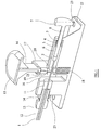
- Figure 3 is a perspective view of the safety switch of Figures 1 and 2.
- Figure 4 is a perspective view of a modified safety switch which embodies the invention; and
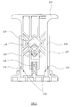
- Figure 5 is a cross-sectional view of part of the safety switch of Figure 4.
- A safety switch which embodies the invention is shown in cross-section in Figure 1. The safety switch comprises a
cable 1 connected to one end of apiston 2 which is held in acylindrical housing 3. Ahelical spring 4 is provided within thecylindrical housing 3 at an opposite end of thepiston 2 from thecable 1. The helical spring pushes against anend surface 5 of thecylindrical housing 3, thereby resiliently biasing thepiston 2 in the direction of thecable 1. - The
piston 2 has a threaded bore 6 which receives a correspondingly threaded end of ahandle 7, thereby securing thehandle 7 to thepiston 2. Thehelical spring 4 passes around ashaft 8 of thehandle 7. - The
cable 1 passes through acable housing 10, which is spaced apart from thecylindrical housing 3. Acylinder 11 with a narrow bore is held within thecable housing 10. Thecable 1 passes through thecylinder 11, the narrow bore of the cylinder acting to prevent dust, liquid etc contaminating the cable within thecable housing 10. - The portion of the
cable 1 which passes from thepiston 2 to thecylinder 11 is exposed. The remainder of thecable 1 shown in Figure 1 is surrounded by asheath 12. Thesheath 12 may for example comprise a hollow cable formed from spiral steel wire with a plastic outer coating. Thecable 1 may slide up and down within thesheath 12; this arrangement is commonly referred to as a Bowden cable. - A
cable tensioner 13 extends from one side of thecable housing 10, and grips thesheath 12. Thetensioner 13 is threaded, and is received in a correspondingly threaded opening in thecable housing 10. The tensioner may be screwed further into thecable housing 10, or screwed in an opposite direction so that it extends further out of thecable housing 10. Since thetensioner 13 grips thesheath 12, whereas thecable 1 is free to slide within thesheath 12, adjusting the tensioner has the effect of drawing thesheath 12 over the cable (thereby changing the amount ofcable 1 which extends beyond either end of the sheath 12). Thetensioner 13 is provided with anut 14 which is used to secure the tensioner in a desired position. - The safety switch is provided with an actuator, which comprises a
button 15 on ashaft 16 that extends perpendicularly to thecable 1. Theshaft 16 of thebutton 15 is held within arectangular housing 17. Ahelical spring 18 is provided in therectangular housing 17, and pushes against a foot of theshaft 16, thereby resiliently biasing theshaft 16 out of the rectangular housing. - The
shaft 16 is provided with a slot 19 (since Figure 1 is in cross-section only half of the slot is shown). Theslot 19 is in two parts, alower part 20 of the slot is narrow, being sufficiently wide to allow thecable 1 to pass through it. Anupper part 21 of theslot 19 is considerably wider, and is circular in shape. - The
button 15 is prevented from being pushed out of therectangular housing 17 under the force of thehelical spring 18, by thecable 1 which passes through the slot 19 (a bottom end of the slot pushes against the cable). - The
cylindrical housing 3,cable housing 10 andrectangular housing 17 are all mounted on abracket 22. Thebracket 22 is provided withopenings 23 which are dimensioned to receive screws or other fasteners, which may be used to fix the safety switch to a wall or some other suitable location. - An opposite end of the
cable 1 and thesheath 12 is connected to a lock (not shown) which is provided at a door of a housing of dangerous electromechanical machinery. The lock is arranged to ensure that access is not allowed to the electromechanical machinery unless the lock is open. In some instances, the lock may be directly connected to an electrical power supply for the electromechanical machinery, with the effect that as soon as the lock is opened the power supply is interrupted and the electromechanical machinery stops operating. During normal use, the lock is electrically operated, and is moved between an open and a closed configuration by actuating an electrical switch. - The safety switch described in relation to Figure 1 may be located within the housing of the electromechanical machinery. In use, during normal operation, the
piston 2 and thebutton 15 of the safety switch are in the configuration shown in Figure 1. Thecable 1 pushes against a lever of the lock at the door of the housing of the electromechanical machinery, thereby retaining the lock in a closed configuration, preventing access to the electromechanical machinery (and in some cases allowing power to be supplied to the electromechanical machinery). - It is possible that a user of the electromechanical machinery may become trapped within the housing. For example, since the lock is electrically operated it will not be possible to operate the lock in the event of a power outage, and this may mean that a user is trapped within the housing.
- The safety switch of Figure 1 is provided at a convenient location, for example around chest height close to the door of the electromechanical machinery. The user presses the
button 15, pushing the button and theshaft 16 downwards against thehelical spring 18. Once thebutton 15 has been pushed down through a required distance, the circularupper part 21 of theslot 19 becomes aligned with thepiston 2. At this point thepiston 2 passes through thecircular part 21 of theslot 19, under the biasing force of thehelical spring 4. This is shown in Figure 2. Thecable 1, which is attached to thepiston 2, is pushed outwards, i.e. thecable 1 effectively lengthens. Since thesheath 13 provided around thecable 1 has not lengthened, this has the effect that an equivalent length of cable is pushed out of the sheath at an opposite end of the sheath. This movement of the cable actuates the lever at the lock, thereby opening the lock. - It will be appreciated that, once the
button 15 has been pushed downwards, and thepiston 2 has passed into thecircular part 21 of theslot 19, thebutton 15 is then secured in the configuration shown in Figure 2. In order for thebutton 15 to return to its raised position, thepiston 2 must be withdrawn from thecircular part 21 of theslot 19 by pulling on thehandle 7. When this is done, thebutton 15 rises automatically, under the bias from thehelical spring 18, and returns to the configuration shown in Figure 1. The action of withdrawing thepiston 2 from thecircular part 21 of theslot 19 draws thecable 1 through thesheath 12, closing the lock. Since the safety switch is located within the housing of the electromechanical machinery, one or more additional switches may be used to ensure that the door of the housing remains unlocked when the safety switch is reset (otherwise the user would upon resetting the safety switch be locked in the housing together with operating electromechanical machinery). The one or more additional switches should be conveniently located outside of the housing, to allow them to be turned on after the user has left the housing and closed the housing door. - In some cases it may be preferred to not allow the safety switch to be returned to the configuration shown in Figure 1 without using a key (for example if the safety switch must be reset by an engineer responsible for safety). Where this is the case, the
handle 7 may be removed from thepiston 2 by unscrewing it. Only the person in possession of thehandle 7 can reset the safety switch, by screwing the handle into thepiston 2 and then withdrawing the piston. Thehandle 7 thus acts as a key. - In order to allow a full understanding of the appearance of the safety switch, a perspective view of the safety switch is shown in Figure 3. The reference numerals shown correspond to those used in relation to Figures 1 and 2.
- Figure 4 is a perspective view of a modified version of the safety switch. Many parts of the safety switch shown in Figure 4 correspond with the safety switch described above, and will not be described again here. Parts which have been modified include the
piston 102 and thebutton 115. Thepiston 102 is provided with a square cross-section rather than the circular cross-section piston shown in Figures 1 and 2. Ahousing 103 which contains thepiston 102 has a corresponding square shaped cross section. The square shaped cross section of thepiston 102 and corresponding cross sectional shape of thehousing 103 has the advantage that it prevents rotation of the piston within the housing. This in turn prevents thecable 101 from becoming twisted. Any non-circular cross sectional shape will provide this advantage. - Figure 5 shows in cross section the
button 115 of the safety switch and itsrectangular housing 117. The button has aslot 119 for receiving thepiston 102. Alower part 120 of the slot is narrow, being sufficiently wide to allow thatcable 101 to pass through it. Anupper part 121 of theslot 119 is considerably wider and has a square cross sectional shape. In use, thebutton 115 is pressed downwards, thereby aligning thepiston 102 with the square cross sectionedopening 119, and allowing the piston to pass through it. The manner of operation of the safety switch is equivalent to that described further above in relation to Figures 1 to 3. -
Protrusions 130 are provided at a lower end of ashaft 116 attached to thebutton 115, and are arranged to engage withlips 131 provided in therectangular housing 117. This engagement prevents thebutton 115 andshaft 116 from being ejected from the housing by thehelical spring 118 in the event that thecable 101 is broken. This is an example of a retaining mechanism which may be used to retain thebutton 115 in thehousing 117. It will be appreciated by those skilled in the art that other retaining mechanisms may be used. - The safety switch may be fabricated from any suitable materials. For example, the
cable 1 and thehelical springs housings bracket 22. - It will be appreciated that the
piston 2 is one example of a cable translator, and that other forms of cable translator may be used (for example the cable translator may comprise a lever or some other arrangement). Although the illustratedpiston 2 has a circular cross section, it may have any other suitable cross section. - Although the actuator is shown as a
button 15 provided on ashaft 16, it will be appreciated that the actuator may have some other suitable form. - The safety switch may be located a considerable distance away from the lock, the maximum distance being dependent upon the length of the
cable 1. Thecable 1 may for example be 1 metre long, 3 metres long or more. - As described above, the safety switch may be provided inside the housing of electromechanical machinery. Alternatively, the safety switch may be outside of the housing, for example provided at a more convenient location than the lock so that it can be easily located in the event of an emergency.
- As was mentioned above, in some instances the lock provided on the door of the electromechanical machinery housing may also be directly connected to an electrical power supply for the electromechanical machinery. The lock may be arranged such that as soon as the lock is opened the power supply is interrupted and the electromechanical machinery stops operating. Where this is the case the safety switch may, in addition to opening the lock, also interrupt the power supply to the electromechanical machinery. This may be useful for example if a user is trapped within the housing when the electromechanical machinery begins to operate. This may happen if a second user has mistakenly closed the door of the housing of the machinery, and closed the lock. It is also possible that the lock does not lock the door of the electromechanical machinery, but instead is arranged only to interrupt the power supply to the electromechanical machinery.
- The safety switch may be connected for example to combined locks and power supply switches (sometimes referred to as interlock switches with guard locking) sold by EJA Engineering Limited of Lancashire, UK. Examples of such switches include switches sold under the names TLS-GD2, Spartan and Atlas.
Claims (17)
- A safety switch for connection to a remote lock and/or a power supply switch, the safety switch comprising a cable having a first end connected to a cable translator moveable between a disengaged position and an engaged position, the cable having a second end for connection to the remote lock and/or power supply switch.
- A safety switch according to claim 1, wherein the safety switch further comprises an actuator moveable between an unactivated position and an activated position, wherein the actuator is arranged such that when it is in the unactivated position it prevents the cable translator from being moved from the disengaged position, and when the actuator is moved to the activated position it allows the cable translator to move to the engaged position.
- A safety switch according to claim 2, wherein the safety switch is arranged such that following movement of the cable translator to the engaged position, the actuator is fixed in the activated position until the cable translator is returned to the disengaged position.
- A safety switch according to claim 2 or claim 3, wherein one end of the cable translator abuts against the actuator when the actuator is in the unactivated position, and the actuator has an opening which allows at least part of the cable translator to pass through the actuator when the actuator is in the activated position.
- A safety switch according to any of claims 2 to 4, wherein the actuator is provided with a retaining mechanism arranged to prevent the actuator being ejected from the housing in the event that the cable is broken.
- A safety switch according to any preceding claim, wherein the cable translator is resiliently biased towards the engaged position.
- A safety switch according to claim 6, wherein once at least part of the cable translator has passed through the actuator, the actuator cannot be returned to the unactivated position without first withdrawing the cable translator from the opening.
- A safety switch according to any preceding claim, wherein the actuator is resiliently biased to the unactivated position.
- A safety switch according to any preceding claim, wherein the cable translator is provided with a handle which allows the cable translator to be easily returned to the disengaged position.
- A safety switch according to claim 9, wherein the handle is removable from cable translator, and the cable translator may be returned to the disengaged position by first engaging the handle with the cable translator
- A safety switch according to any preceding claim, wherein the cable is at least in part surrounded by sheath which is fixed such that the cable moves within the sheath when the cable translator moves.
- A safety switch according to claim 11, wherein the second end of the cable protrudes from the sheath to allow the cable to be connected to the lock and/or the power supply switch.
- A safety switch according to any preceding claim, wherein the safety switch further comprises a housing having a bracket to allow the safety switch to be mounted on a wall or other suitable surface.
- A safety switch according to any preceding claim, wherein the lock and/or the power supply switch is arranged to be electrically operated during normal use.
- A safety switch according to any preceding claim, wherein the lock and/or the power supply switch is configured such that it may be locally operated without using the safety switch.
- A safety switch according to any preceding claim, wherein the cable translator has a circular cross section.
- A safety switch according to any of claims 1 to 15, wherein the cable translator has a non-circular cross section.
Priority Applications (1)
| Application Number | Priority Date | Filing Date | Title |
|---|---|---|---|
| US11/489,821 US7687728B2 (en) | 2005-07-20 | 2006-07-20 | Safety switch |
Applications Claiming Priority (1)
| Application Number | Priority Date | Filing Date | Title |
|---|---|---|---|
| GB0514868A GB0514868D0 (en) | 2005-07-20 | 2005-07-20 | Safety switch |
Publications (2)
| Publication Number | Publication Date |
|---|---|
| EP1746614A1 true EP1746614A1 (en) | 2007-01-24 |
| EP1746614B1 EP1746614B1 (en) | 2008-08-27 |
Family
ID=34897502
Family Applications (1)
| Application Number | Title | Priority Date | Filing Date |
|---|---|---|---|
| EP20060253656 Ceased EP1746614B1 (en) | 2005-07-20 | 2006-07-12 | Safety switch |
Country Status (3)
| Country | Link |
|---|---|
| EP (1) | EP1746614B1 (en) |
| DE (1) | DE602006002446D1 (en) |
| GB (1) | GB0514868D0 (en) |
Cited By (2)
| Publication number | Priority date | Publication date | Assignee | Title |
|---|---|---|---|---|
| CN107100430A (en) * | 2017-04-10 | 2017-08-29 | 九江精密测试技术研究所 | A kind of mechanical locking device with safeguard protection |
| CN110931285A (en) * | 2019-12-26 | 2020-03-27 | 北京科锐配电自动化股份有限公司 | Interlocking structure for cable chamber door of ring main unit |
-
2005
- 2005-07-20 GB GB0514868A patent/GB0514868D0/en not_active Ceased
-
2006
- 2006-07-12 DE DE200660002446 patent/DE602006002446D1/en active Active
- 2006-07-12 EP EP20060253656 patent/EP1746614B1/en not_active Ceased
Non-Patent Citations (1)
| Title |
|---|
| No Search * |
Cited By (2)
| Publication number | Priority date | Publication date | Assignee | Title |
|---|---|---|---|---|
| CN107100430A (en) * | 2017-04-10 | 2017-08-29 | 九江精密测试技术研究所 | A kind of mechanical locking device with safeguard protection |
| CN110931285A (en) * | 2019-12-26 | 2020-03-27 | 北京科锐配电自动化股份有限公司 | Interlocking structure for cable chamber door of ring main unit |
Also Published As
| Publication number | Publication date |
|---|---|
| GB0514868D0 (en) | 2005-08-24 |
| DE602006002446D1 (en) | 2008-10-09 |
| EP1746614B1 (en) | 2008-08-27 |
Similar Documents
| Publication | Publication Date | Title |
|---|---|---|
| US12624574B2 (en) | Locking assembly with spring mechanism | |
| US6098433A (en) | Lock for safes and other security devices | |
| US4583382A (en) | Reversible latch assembly with integrated function | |
| CA2638004C (en) | Latches for gates and doors | |
| US10329795B2 (en) | Lock | |
| EP3707327B1 (en) | Lever compression latch | |
| US20160108650A1 (en) | Opposed hook sliding door lock | |
| US8333411B2 (en) | Lock mechanism | |
| RU2633237C2 (en) | Door lock of vehicle | |
| US20040112100A1 (en) | Electronic door locking apparatus | |
| EP1746614B1 (en) | Safety switch | |
| US4465311A (en) | Remote control locking system | |
| US5004278A (en) | Door lock having security device | |
| US7687728B2 (en) | Safety switch | |
| KR100485427B1 (en) | Padlockable emergency stop buttton | |
| CN112513393A (en) | Self-locking button | |
| KR0131801Y1 (en) | Unlocking position restraint type latch device | |
| IE930044A1 (en) | Improvements in or relating to handle assemblies | |
| CN1313443A (en) | Handle device for inserting lock | |
| KR200452305Y1 (en) | Door lock with handle integrated integral lock button | |
| JP4956457B2 (en) | Emergency stop pushbutton switch | |
| KR102362325B1 (en) | Locking apparatus of safety lever | |
| KR100713073B1 (en) | Lock module for door lock device | |
| EP4234850B1 (en) | A door handle arrangement | |
| CN206819899U (en) | Hand controls, circuit breakers and electrical cabinets |
Legal Events
| Date | Code | Title | Description |
|---|---|---|---|
| PUAI | Public reference made under article 153(3) epc to a published international application that has entered the european phase |
Free format text: ORIGINAL CODE: 0009012 |
|
| AK | Designated contracting states |
Kind code of ref document: A1 Designated state(s): AT BE BG CH CY CZ DE DK EE ES FI FR GB GR HU IE IS IT LI LT LU LV MC NL PL PT RO SE SI SK TR |
|
| AX | Request for extension of the european patent |
Extension state: AL BA HR MK YU |
|
| 17P | Request for examination filed |
Effective date: 20070713 |
|
| AKX | Designation fees paid |
Designated state(s): DE FR GB IT |
|
| GRAP | Despatch of communication of intention to grant a patent |
Free format text: ORIGINAL CODE: EPIDOSNIGR1 |
|
| GRAS | Grant fee paid |
Free format text: ORIGINAL CODE: EPIDOSNIGR3 |
|
| GRAA | (expected) grant |
Free format text: ORIGINAL CODE: 0009210 |
|
| AK | Designated contracting states |
Kind code of ref document: B1 Designated state(s): DE FR GB IT |
|
| REG | Reference to a national code |
Ref country code: GB Ref legal event code: FG4D |
|
| REF | Corresponds to: |
Ref document number: 602006002446 Country of ref document: DE Date of ref document: 20081009 Kind code of ref document: P |
|
| RAP2 | Party data changed (patent owner data changed or rights of a patent transferred) |
Owner name: ROCKWELL AUTOMATION LIMITED |
|
| PLBE | No opposition filed within time limit |
Free format text: ORIGINAL CODE: 0009261 |
|
| STAA | Information on the status of an ep patent application or granted ep patent |
Free format text: STATUS: NO OPPOSITION FILED WITHIN TIME LIMIT |
|
| 26N | No opposition filed |
Effective date: 20090528 |
|
| PG25 | Lapsed in a contracting state [announced via postgrant information from national office to epo] |
Ref country code: IT Free format text: LAPSE BECAUSE OF FAILURE TO SUBMIT A TRANSLATION OF THE DESCRIPTION OR TO PAY THE FEE WITHIN THE PRESCRIBED TIME-LIMIT Effective date: 20080827 |
|
| REG | Reference to a national code |
Ref country code: FR Ref legal event code: PLFP Year of fee payment: 10 |
|
| REG | Reference to a national code |
Ref country code: FR Ref legal event code: PLFP Year of fee payment: 11 |
|
| REG | Reference to a national code |
Ref country code: FR Ref legal event code: PLFP Year of fee payment: 12 |
|
| REG | Reference to a national code |
Ref country code: FR Ref legal event code: PLFP Year of fee payment: 13 |
|
| PGFP | Annual fee paid to national office [announced via postgrant information from national office to epo] |
Ref country code: FR Payment date: 20200623 Year of fee payment: 15 |
|
| PGFP | Annual fee paid to national office [announced via postgrant information from national office to epo] |
Ref country code: GB Payment date: 20200624 Year of fee payment: 15 |
|
| PGFP | Annual fee paid to national office [announced via postgrant information from national office to epo] |
Ref country code: DE Payment date: 20200622 Year of fee payment: 15 |
|
| REG | Reference to a national code |
Ref country code: DE Ref legal event code: R119 Ref document number: 602006002446 Country of ref document: DE |
|
| GBPC | Gb: european patent ceased through non-payment of renewal fee |
Effective date: 20210712 |
|
| PG25 | Lapsed in a contracting state [announced via postgrant information from national office to epo] |
Ref country code: GB Free format text: LAPSE BECAUSE OF NON-PAYMENT OF DUE FEES Effective date: 20210712 Ref country code: DE Free format text: LAPSE BECAUSE OF NON-PAYMENT OF DUE FEES Effective date: 20220201 |
|
| PG25 | Lapsed in a contracting state [announced via postgrant information from national office to epo] |
Ref country code: FR Free format text: LAPSE BECAUSE OF NON-PAYMENT OF DUE FEES Effective date: 20210731 |