EP1746593A1 - Disc recorder/reproducer - Google Patents
Disc recorder/reproducer Download PDFInfo
- Publication number
- EP1746593A1 EP1746593A1 EP05739028A EP05739028A EP1746593A1 EP 1746593 A1 EP1746593 A1 EP 1746593A1 EP 05739028 A EP05739028 A EP 05739028A EP 05739028 A EP05739028 A EP 05739028A EP 1746593 A1 EP1746593 A1 EP 1746593A1
- Authority
- EP
- European Patent Office
- Prior art keywords
- cartridge
- disk
- disk cartridge
- recording
- disposed
- Prior art date
- Legal status (The legal status is an assumption and is not a legal conclusion. Google has not performed a legal analysis and makes no representation as to the accuracy of the status listed.)
- Withdrawn
Links
Images










Classifications
-
- G—PHYSICS
- G11—INFORMATION STORAGE
- G11B—INFORMATION STORAGE BASED ON RELATIVE MOVEMENT BETWEEN RECORD CARRIER AND TRANSDUCER
- G11B17/00—Guiding record carriers not specifically of filamentary or web form, or of supports therefor
- G11B17/02—Details
- G11B17/04—Feeding or guiding single record carrier to or from transducer unit
- G11B17/041—Feeding or guiding single record carrier to or from transducer unit specially adapted for discs contained within cartridges
-
- G—PHYSICS
- G11—INFORMATION STORAGE
- G11B—INFORMATION STORAGE BASED ON RELATIVE MOVEMENT BETWEEN RECORD CARRIER AND TRANSDUCER
- G11B23/00—Record carriers not specific to the method of recording or reproducing; Accessories, e.g. containers, specially adapted for co-operation with the recording or reproducing apparatus ; Intermediate mediums; Apparatus or processes specially adapted for their manufacture
- G11B23/02—Containers; Storing means both adapted to cooperate with the recording or reproducing means
- G11B23/03—Containers for flat record carriers
- G11B23/0301—Details
- G11B23/0308—Shutters
-
- G—PHYSICS
- G11—INFORMATION STORAGE
- G11B—INFORMATION STORAGE BASED ON RELATIVE MOVEMENT BETWEEN RECORD CARRIER AND TRANSDUCER
- G11B17/00—Guiding record carriers not specifically of filamentary or web form, or of supports therefor
- G11B17/02—Details
- G11B17/04—Feeding or guiding single record carrier to or from transducer unit
- G11B17/041—Feeding or guiding single record carrier to or from transducer unit specially adapted for discs contained within cartridges
- G11B17/043—Direct insertion, i.e. without external loading means
-
- G—PHYSICS
- G11—INFORMATION STORAGE
- G11B—INFORMATION STORAGE BASED ON RELATIVE MOVEMENT BETWEEN RECORD CARRIER AND TRANSDUCER
- G11B17/00—Guiding record carriers not specifically of filamentary or web form, or of supports therefor
- G11B17/02—Details
- G11B17/04—Feeding or guiding single record carrier to or from transducer unit
- G11B17/041—Feeding or guiding single record carrier to or from transducer unit specially adapted for discs contained within cartridges
- G11B17/044—Indirect insertion, i.e. with external loading means
- G11B17/046—Indirect insertion, i.e. with external loading means with pivoting loading means
-
- G—PHYSICS
- G11—INFORMATION STORAGE
- G11B—INFORMATION STORAGE BASED ON RELATIVE MOVEMENT BETWEEN RECORD CARRIER AND TRANSDUCER
- G11B33/00—Constructional parts, details or accessories not provided for in the other groups of this subclass
- G11B33/02—Cabinets; Cases; Stands; Disposition of apparatus therein or thereon
Definitions
- the present invention relates to a disk recording and/or reproducing apparatus including cartridge drop preventive means for preventing a disk cartridge from being dropped by momentum from a cartridge holder during ejection.
- the apparatus includes a pull plate that traverses a cartridge insertion path and is guided so as to be moved in parallel with a cartridge insertion direction. An inserted cartridge is abutted against the pull plate.
- the apparatus further includes a fitting holding member that fits elastically into recessed portions of the cartridge on both sides of the pull plate. The cartridge is held in position by this fitting holding member relative to the pull plate. During ejection, the pull plate is stopped at a predetermined position by a stopper. (See, for example, Japanese Patent Laid-open No. 2001-189043 (paragraphs 0056 through 0068, and the like).)
- the disk cartridge includes holding recessed portions disposed on a bottom surface of a case main body thereof.
- the holding recessed portions are engaged with, and held by, capturing bodies included in a disk drive.
- a closure reaction of the shutter spring during ejection operation is used to prevent the case main body from jumping out of a loading port of the disk drive.
- the cartridge drop preventive means disclosed in Japanese Patent Laid-open No. 2001-189043 uses the pull plate, the fitting holding member, the stopper, a lever member, and the like. This has presented the following problems: specifically, an increased number of parts used; a complicated structure; and an increased cost.
- the cartridge drop preventive means disclosed in Japanese Patent Laid-open No. 2000-173223 includes the holding recessed portions disposed on the bottom surface of the case main body of the disk cartridge and the holding recessed portions are engaged with, and held by, the capturing bodies included in the disk drive. This has led to a problem, in which the capturing bodies cause the disk cartridge to raise, or the like.
- the disk recording and/or reproducing apparatus includes a cartridge holder, a chassis, recording and/or reproducing means, an eject lever, urge means, and cartridge drop preventive means.
- a disk cartridge is inserted in, and held by, the cartridge holder.
- the chassis supports the cartridge holder movably between a cartridge insertion/removal position and a recording/reproducing position.
- the recording and/or reproducing means is disposed in the chassis and records and/or reproduces the disk cartridge.
- the eject lever is disposed in the chassis movably in an insertion/removal direction of the disk cartridge and movably in a direction toward or away from the chassis. The eject lever is moved by being pushed by the disk cartridge inserted into the cartridge holder.
- the urge means gives the eject lever a moving force in a disk cartridge unloading direction and an urging force in a direction of approaching the chassis.
- the cartridge drop preventive means gives a braking force to the disk cartridge being unloaded by the urge means, thereby preventing the disk cartridge from dropping off from the cartridge holder.
- the cartridge drop preventive means is formed from a spring member disposed on a first side surface plate of the cartridge holder.
- the spring member makes a sliding contact with a first side surface of the disk cartridge during unloading of the disk cartridge so as to give the disk cartridge a braking force.
- the cartridge drop preventive means is formed to include an elastic flap portion and a protruded portion.
- the elastic flap portion extends toward a cartridge insertion port in the cartridge holder.
- the protruded portion is disposed on a leading end portion of the elastic flap portion and makes a sliding contact with the first side surface of the disk cartridge during unloading of the disk cartridge.
- Still another arrangement is made to keep the protruded portion disposed on the leading end of the elastic flap portion in a noncontact state relative to the first side surface of the disk cartridge when storage of the disk cartridge in the cartridge holder is completed.
- the cartridge drop preventive means is disposed on a first side surface plate opposing a second side surface plate of the cartridge holder, on which a shutter lock release member is disposed.
- the cartridge drop preventive means is formed by cutting and raising the first side surface of the cartridge holder.
- a disk recording and/or reproducing apparatus to which the present invention is applied will be described below in the following order: (1) General construction of the apparatus and construction of the cartridge drop preventive means; (2) Construction of the disk cartridge; (3) Construction of the cartridge holder; (4) Construction of the chassis; (5) Construction of the recording and/or reproducing means; (6) Construction of the eject lever; (7) Construction of the urge means and the eject lever lock means; (8) Construction of the lock release means; (9) Other arrangements; and (10) Operation.
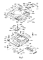
- FIG. 1 is a perspective view showing the disk recording and/or reproducing apparatus, to which the present invention is applied.
- Fig. 2 is a plan view as viewed from a backside.
- Fig. 3 is an exploded perspective view.
- a disk recording and/or reproducing apparatus 101 includes a cartridge holder 102, a chassis 103, recording and/or reproducing means 104, an eject lever 105, urge means 106, eject lever lock means 107, lock release means 108, and cartridge drop preventive means 221.
- a disk cartridge 1 is inserted in, and held by, the cartridge holder 102.
- the chassis 103 supports the cartridge holder 102 movably between a cartridge insertion/removal position and a recording/reproducing position.
- the recording and/or reproducing means 104 is disposed in the chassis 103 and records and/or reproduces the disk cartridge 1.
- the eject lever 105 is disposed in the chassis 103 rotationally movably (hereinafter referred to simply as “rotatably") in an insertion/removal direction of the disk cartridge 1 and movably in a direction toward or away from the chassis 103.
- the eject lever 105 is rotated by being pushed by the disk cartridge 1 inserted into the cartridge holder 102.
- the urge means 106 gives the eject lever 105 a rotational force in a disk cartridge unloading direction and an urging force in a direction of approaching the chassis 103.
- the eject lever lock means 107 locks the eject lever 105, which has been rotated by the insertion of the disk cartridge 1, onto the chassis 103.
- the lock release means 108 releases a lock of the eject lever 105 by the eject lever lock means 107 when the cartridge holder 102 is rotated from the recording/reproducing position to the cartridge insertion/removal position.
- the cartridge drop preventive means 221 is formed from a flat spring member disposed on a first side surface plate 102b of the cartridge holder 102.
- the flat spring member makes a sliding contact with a first side surface 3b of the disk cartridge 102 during unloading of the disk cartridge so as to give the disk cartridge 1 a braking force.
- the cartridge drop preventive means 221 includes an elastic flap portion 222 and a protruded portion 223.
- the elastic flap portion 222 extends toward a cartridge insertion port 102k in the cartridge holder 102.
- the protruded portion 223 is disposed on a leading end portion of the elastic flap portion 222 and contacts the first side surface 3b of the disk cartridge 1 during unloading of the disk cartridge.
- the protruded portion 223 fits into a recessed portion 61 disposed in the first side surface 3b of the disk cartridge 1 for releasing a first side pressure and is kept in a noncontact condition with respect to the first side surface 3b when storage of the disk cartridge 1 in the cartridge holder 102 is completed.
- a second side surface plate 102c opposing the first side surface plate 102b of the cartridge holder 102 including the cartridge drop preventive means 221 includes a shutter lock release member 116.
- the cartridge drop preventive means 221 is formed by cutting and raising the first side surface plate 102b of the cartridge holder 102, or by providing a window portion in the first side surface plate 102b of the cartridge holder 102 and the attaching the cartridge drop preventive means 221 made of a flat spring so as to face the window portion.
- Fig. 9 is a perspective view showing the disk cartridge 1 as viewed from an upper half side.
- Fig. 10 is a perspective view showing the disk cartridge 1 as viewed from a lower half side.
- Fig. 11 is a perspective view showing a condition, in which a shutter member is slid to expose an opening portion for recording and/or reproducing.
- the disk cartridge 1 includes a disk-shaped recording medium 2, a cartridge main body 3, a shutter member 4, a shutter movement restriction member 5, an urge member 6, and a deformation preventive portion 7.
- the cartridge main body 3 accommodates the disk-shaped recording medium 2 rotatably within a circular disk storage portion and includes a recording and/or reproducing opening portion 34 that allows part of the disk-shaped recording medium 2 to face an outside.
- the shutter member 4 is mounted in the cartridge main body 3 movably between a position of closing the recording and/or reproducing opening portion 34 and a position of opening the recording and/or reproducing opening portion 34.
- the shutter movement restriction member 5 (see Fig.
- the urge member 6 urges the shutter movement restriction member 5 in a direction of being engaged with the movement restriction portion 3e disposed in the cartridge main body 3.
- the deformation preventive portion 7 prevents the urge member 6 from being deformed by an external force.
- the urge member 6 includes an extension flap 6a and an elastic displacement flap 6c.
- the extension flap 6a is extended from one side of the shutter member 4.
- the elastic displacement flap 6c is formed by folding back the extension flap 6a via a fold back portion 6b disposed at a leading end portion of the extension flap 6a so as to overlap an inside of the extension flap 6a.
- the deformation preventive portion 7 is disposed on a back of the leading end portion of the urge member 6.
- the deformation preventive portion 7 supports the urge member 6 from the back, thereby preventing the urge member 6 from being deformed by an external force.
- the urge member 6 makes a leading end portion of the elastic displacement flap 6c press a pressed portion 57 disposed on the side of one end of the shutter movement restriction member 5.
- the urge member 6 thereby rotates the shutter movement restriction member 5 about a mounting shaft 8 in a clockwise direction.
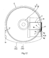
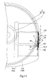
- An engagement portion 58 disposed on the side of the other end of the shutter movement restriction member 5 is thus located at an engageable position relative to the movement restriction portion 3e disposed in the cartridge main body 3.
- the engagement portion 58 disposed on the side of the other end of the shutter movement restriction member 5 is engaged with the movement restriction portion 3e disposed in the cartridge main body 3, thereby preventing the shutter member 4 from moving.
- the pressed portion 57 is pressed, in opposition to an urging force of the elastic displacement flap 6c, by a protruded portion 117 of the shutter lock release member 116 disposed on the second side surface plate 102c of the cartridge holder 102 to be described next, the shutter movement restriction member 5 rotates about the mounting shaft 8 in a counterclockwise direction as shown in Fig. 13.
- the engagement portion 58 is thereby escaped to a position, at which engagement with the movement restriction portion 3e is disabled.
- the shutter member 4 is thus allowed to move in the direction of opening the recording and/or reproducing opening portion 34.
- the disk-shaped recording medium 2 is formed by mounting a chucking hub 22 at a center of an optical disk 21 on which gaming software or the like is recorded.
- the optical disk 21 is formed to have a small diameter of about 50 mm.
- the chucking hub 22 is formed from a stainless steel or other magnetic metal attracted by a magnet.
- the cartridge main body 3 is formed by making peripheral walls 31a, 32a of upper and lower halves 31, 32 abut against each other. Referring to Fig. 12, arcuate ribs 31b, 32b constituting the disk storage portion are disposed on an inside of the peripheral walls 31a, 32a.
- the cartridge main body 3 includes a front surface 3a (a side surface on the side of an insertion end to the disk recording and/or reproducing apparatus to be described later), right and left side surfaces (hereinafter referred to as first and second side surfaces) 3b, 3c, and a back surface 3d.
- the front surface 3a is formed into an arcuate surface (a semicircular surface) having substantially the same radius of curvature as the optical disk 21.
- the first and second side surfaces 3b, 3c, each continuing to the front surface 3a are formed into flat surfaces that run in parallel with each other.
- the back surface 3d opposing the front surface 3a and continuing to the first and second side surfaces 3b, 3c is formed into a mildly continuing curved surface.
- the lower half 32 includes a driving opening portion 33 disposed at a center thereof.
- the driving opening portion 33 allows the hub 22 of the disk-shaped recording medium 2 to face the outside.
- the lower half 32 also includes the recording and/or reproducing opening portion 34 disposed over an area covering from a point near the driving opening portion 33 to the second side surface 3c.
- the recording and/or reproducing opening portion 34 allows an information recording surface of the optical disk 21 to face the outside.
- the hub 22 of the disk-shaped recording medium 2 is magnetically clamped onto a disk table 170 of the disk recording and/or reproducing apparatus 101 via the driving opening portion 33.
- An optical pickup 152 of the disk recording and/or reproducing apparatus 101 records and/or reproduces information relative to the optical disk 21 of the disk-shaped recording medium 2 via the recording and/or reproducing opening portion 34.
- the disk cartridge 1 also includes a recessed step portion (hereinafter referred to as a first dent portion) 35 disposed in an area covering from an outer surface 32c of the lower half 32 to the peripheral wall of the second side surface 3c.
- the first dent portion 35 has the following functions. Specifically, the first dent portion 35 ensures that the shutter member 4 to be described next is mounted so as not to protrude from the outer surface 32b of the lower half 32 and the second side surface 3c; or more specifically, the first dent portion 35 ensures that the shutter member 4 is mounted flush with the outer surface 32c of the lower half 32 and an outer surface of the peripheral wall on the side of the second side surface 3c. Further, the first dent portion 35 restricts a movement range of the shutter member 4.
- An end portion of the first dent portion 35 on the side of the driving opening portion 33 is formed as a second dent portion 36 that is even deeper than the first dent portion 35.
- a folded portion 44a disposed at a leading end of an opening open/close portion 44 of the shutter member 4 to be described next is inserted into the second dent portion 36.
- the second dent portion 36 is closed at a position upward of the folded portion 4a by a shutter guide plate 37 mounted to the lower half 32. Further, the shutter guide plate 37 prevents the folded portion 44a at the leading end of the opening open/close portion 44 from curving upward.
- the shutter guide plate 37 is also mounted in the lower half 32 in a condition, in which the shutter guide plate 37 remains flush with the outer surface of the lower half 32.
- the upper half 31 includes a guide groove 38 that extends in a moving direction of the shutter member 4.
- the guide groove 38 is disposed in the peripheral wall 31a on the side of the second side surface 3c.
- the peripheral wall 32a on the side of the second side surface 3c of the lower half 32 is removed. This arrangement forms an opening portion 39 for shutter member guiding in a space formed with the peripheral wall 31a on the side of the second side surface 3c of the upper half 31.
- an area from the second side surface 3c to the front surface 3a of the cartridge main body 3 includes a shutter lock release member guide groove 40.
- the shutter lock release member guide groove 40 continues into the opening portion 39 for shutter member guiding.
- the other side surface of the cartridge main body 3, that is, the first side surface 3b includes a function enhancement groove 41 and the side pressure releasing recessed portion 61.
- the side pressure releasing recessed portion 61 functions as follows. Specifically, when storage of the disk cartridge 1 in the cartridge holder 102 is completed, the protruded portion 223 of the cartridge drop preventive means 221 fits into the recessed portion 61 and is kept in a noncontact condition with respect to the first side surface 3b of the cartridge main body 3. The side pressure releasing recessed portion 61 thereby releases a side pressure by the cartridge drop preventive means 221 on the cartridge holder 102.
- an outer surface of the lower half 32 on the side of the front surface 3a includes a pair of positioning holes 42, 43.
- the shutter member 4 includes the flat plate-like opening open/close portion 44 and an assembly portion 45.
- the opening open/close portion 44 closes the recording and/or reproducing opening portion 34.
- the assembly portion 45 is used for assembling the shutter member 4 to the cartridge main body 3 so that the shutter member 4 is movable between the position of opening the recording and/or reproducing opening portion 34 and the position of closing the recording and/or reproducing opening portion 34 with the opening open/close portion 44 overlapped with the first dent portion 35 of the lower half 32.
- the assembly portion 45 includes a first movement guide flap 46 and a second movement guide flap 47.
- the first movement guide flap 46 is formed by bending the side of one end of the opening open/close portion 44 substantially at a right angle.
- the second movement guide flap 47 is formed by bending a leading end portion of the first movement guide flap 46 substantially at a right angle so as to run in the same direction as the opening open/close portion 44.
- the first movement guide flap 46 includes an opening portion 48 for pressing operation at a central portion thereof.
- the pressed portion 57 of the shutter movement restriction member 5 to be next described in detail faces this opening portion 48.
- the first movement guide flap 46 also includes third and fourth movement guide flaps 49, 50 disposed on both sides in the shutter movement direction and at substantially a central portion in a thickness direction of the cartridge main body 3.
- the third and fourth movement guide flaps 49, 50 run substantially in parallel with the second movement guide flap 47.
- the third and fourth movement guide flaps 49, 50 also include lock tabs 51a, 51b at leading end portions thereof, respectively.
- the lock tabs 51a, 51b extend in a direction of leaving away from the opening open/close portion 44.
- the shaft portion 52 allows the shutter movement restriction member 5 to be mounted rotatably.
- An end portion of the opening open/close portion 44 opposite to the assembly portion 45 includes the folded portion 44a for upward curving prevention.
- the shutter member 4 is formed by bending a metal plate blanked to a predetermined shape.
- the shutter member 4 is slidably mounted on the side of the second side surface 3c of the cartridge main body 3 as detailed in the following. Specifically, the first movement guide flap 46 is aligned with the shutter Rick release member guide groove 40 in the second side surface 3c of the cartridge main body 3. The second movement guide flap 47 is then inserted into the guide groove 38 included in the upper half 31. The third and fourth movement guide flaps 49, 50 are inserted into the cartridge main body 3 through the opening portion 39 for guiding the shutter member. The lock tab 51a disposed on the leading end of the third movement guide flap 49 is then engaged with a groove 32e included in a bottom surface of the peripheral wall 31a of the upper half 31. The lock tab 51b disposed on the leading end of the fourth movement guide flap 50 is engaged with an inner surface 32f of the peripheral wall 31a of the upper half 31.
- the opening open/close portion 44 closes the recording and/or reproducing opening portion 34.
- the opening open/close portion 44 opens the recording and/or reproducing opening portion 34.
- the shutter movement restriction member 5 includes a flat plate-like main body portion 56, the pressed portion 57, and the engagement portion 58.
- the main body portion 56 includes a bearing hole 55 located at a central portion thereof.
- the pressed portion 57 is located at one end portion of the main body portion 56.
- the engagement portion 58 is located at the other end portion of the main body portion 56.
- the shutter movement restriction member 5 further includes a protruded portion 59 for inhibiting rotation disposed on the end portion thereof, in which the pressed portion 57 of the main body 56 is provided.
- the pressed portion 57 and the engagement portion 58 are formed by bending one end portion and the other end portion of the main body portion 56 substantially at a right angle in the same direction.
- the shutter movement restriction member 5 is formed by bending a metal plate blanked to a predetermined shape.
- the shutter movement restriction member 5 is rotatably mounted in the fourth movement guide flap 50 by inserting the boss-shaped shaft portion 52 on the fourth movement guide flap 50 of the shutter member 4 in the bearing hole 55.
- the shutter movement restriction member 5 is rotated until the protruded portion 59 for inhibiting rotation abuts on the inner surface of the first movement guide flap 46 of the shutter member 4, the pressed portion 56 faces the opening portion 48 for pressing operation disposed at the central portion of the first movement guide flap 46 of the shutter member 4 as shown in Fig. 11.
- the engagement portion 58 becomes engageable with the movement restriction portion 3e disposed on the cartridge main body 3, thus inhibiting the shutter member 4 from moving.
- the urge member 6 includes the extension flap 6a and the elastic displacement flap 6c.
- the extension flap 6a is extended from one side of the shutter member 4.
- the elastic displacement flap 6c is formed by folding back the extension flap 6a via the fold back portion 6b disposed at the leading end portion of the extension flap 6a. (See Fig. 14.)
- the extension flap 6a is formed by being curved so as to advance into the cartridge main body 3 through the opening portion 39 for guiding the shutter member when the shutter member 4 is assembled in the cartridge main body 3.
- the elastic displacement flap 6c is folded back in a curved condition so as to overlap the inner surface of the extension flap 6c.
- the leading end portion of the elastic displacement flap 6c is to press the pressed portion 57 disposed on the side of one end of the shutter movement restriction member 5, thus causing the pressed portion 57 to face the opening portion 48 for pressing operation disposed at the central portion of the first movement guide flap 46 of the shutter member 4.
- the extension flap 6a makes the elastic displacement flap 6c long, thereby allowing spring constant of the urge member 6 to be adjusted.
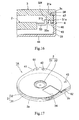
- Fig. 17 is a view showing a disk cartridge according to another embodiment of the present invention.
- a disk cartridge 1A adopts what is called a shutter-less structure having no shutter member 4.
- the shutter-less disk cartridge 1A includes a function enhancement groove 41 and a first side pressure releasing recessed portion 61.
- the function enhancement groove 41 is disposed in a first side surface 3b of a cartridge main body 3.
- the side pressure releasing recessed portion 61 functions as follows.
- a protruded portion 223 of a cartridge drop preventive means 221 fits into the recessed portion 61 and is kept in a noncontact condition with respect to the first side surface 3b of the cartridge main body 3 of the disk cartridge 1.
- the side pressure releasing recessed portion 61 thereby releases a side pressure by the cartridge drop preventive means 221 on the cartridge holder 102.
- the function enhancement groove 41 is formed closer to the side of an insertion end as compared with the first side pressure releasing recessed portion 61.
- a second side surface 3c includes a second side pressure releasing recessed portion 62.
- the second side pressure releasing recessed portion 62 functions as follows.
- a protruded portion 117 at a leading end of a shutter lock release member 116 disposed on a second side surface plate 102c of a cartridge holder 102 to be described next fits into the recessed portion 62 and is kept in a noncontact condition with respect to the second side surface 3c of the cartridge main body 3 of the disk cartridge 1.
- the second side pressure releasing recessed portion 62 thereby removes a side pressure by the shutter lock release member 116 on the cartridge holder 102.
- the cartridge holder 102 includes an upper surface plate (top surface plate) 102a, the right and left side surface plates (hereinafter referred to as the first and second side surface plates) 102b, 102c, a pair of right and left cartridge support portions 102d, 102e, and receiving surface portions 102f, 102g.
- the upper surface plate 102a is substantially a square.
- the first and second side surface plates 102b, 102c are formed by bending right and left side portions of the upper surface plate 102a downwardly substantially at a right angle.
- the cartridge support portions 102d, 102e are formed by bending lower ends of the first and second side surface plates 102b, 102c inwardly substantially at a right angle.
- the cartridge support portions 102d, 102e support right and left side portions on the lower surface of the disk cartridge 1 inserted in the cartridge holder 102.
- the receiving surface portions 102f, 102g are formed by bending front ends of the cartridge support portions 102d, 102e downwardly.
- the upper surface plate 102a, the first and second side surface plates 102b, 102c, the pair of right and left cartridge support portions 102d, 102e, and the like constitute an insertion port 102k of the disk cartridge 1 and a storage portion that continues thereto.
- a bridge plate 102m is attached at a position closer to the insertion port of the pair of right and left cartridge support portions 102d, 102e.
- the bridge plate 102m is attached so as to cross over the cartridge support portions 102d, 102e.
- the bridge plate 102m serves as reinforcement for preventing the pair of cartridge support portions 102d, 102e from being easily deformed.
- the bridge plate 102m also functions to prevent the disk cartridge 1 from jumping out from a space between the pair of cartridge support portions 102d, 102e.
- the upper surface plate 102a has a hexagonal opening portion 111 blanked at a center thereof.
- the opening portion 111 is for reducing weight of the cartridge holder 102.
- a pair of right and left, or first and second flat springs 112, 113 is disposed on both sides of the opening portion 111.
- the first and second flat springs 112, 113 are bent so as to advance into the storage portion from the insertion port 102k.
- the first and second flat springs 112, 113 are as such designed to press an upper surface of the disk cartridge 1 inserted into the storage portion, thereby pressing the disk cartridge 1 against the cartridge support portions 102d, 102e.
- a pair of right and left, or third and fourth flat springs 114, 115 is disposed on the side of a front end of the opening portion 111.
- the third and fourth flat springs 114, 115 are bent upwardly toward an upper side of the upper surface plate 102a.
- the third and fourth flat springs 114, 115 are designed to permit easy insertion, assembly, or a related task performed for the cartridge holder 102 relative to a cartridge holder storage portion or the like of an electronic apparatus.
- the first through fourth flat springs 112 to 115 are formed by blanking part of the upper surface plate 102a of the disk cartridge 1.
- the recessed lock release means mounting portion 102h is formed in the following space.
- the space is specifically between the second flat spring 113 and the second side surface plate 102c of the cartridge holder 102, and between the arcuate front surface 3a of the disk cartridge 1 inserted in the cartridge holder 102 and the second side surface plate 102c of the cartridge holder 102.
- the space is what is called a dead space.
- two cylindrical boss-shaped protrusions 102n are formed on the second side surface plate 102c of the cartridge holder 102 facing the lock release means mounting portion 102h.
- the lock release means 108 is mounted through the following mounting steps in the substantially triangular dead space formed by the disk cartridge 1 inserted in the cartridge holder 102, and the arcuate front surface 3a and the side surface 3c of the cartridge main body 3. Specifically, the boss-shaped protrusions 102n are inserted in protrusion fitting holes 108g in the mounting portion 108a. An overlapping portion 108b is overlapped with the upper surface of the lock release means mounting portion 102h. The elastic flap portion 108c and the eject lever operating portion 108d are then inserted in the cartridge holder 102 and leading end portions of the boss-shaped protrusions 102n are then caulked to enlarge diameters thereof.
- the second side surface plate 102c of the cartridge holder 102 is mounted with the shutter lock release member 116 for releasing locking of the shutter member 4 by the shutter movement restriction member 5 of the disk cartridge 1.
- the lock release member 116 is formed from a flat spring. Like the mounting portion 108a of the lock release means 108, the lock release member 116 is immovably attached to the second side surface plate 102c of the cartridge holder 102. The side on one end portion of the lock release member 116 in a length direction is secured by the boss-shaped protrusions 102n disposed on the second side surface plate 102c of the cartridge holder 102. The lock release member 116 extends along the second side surface plate 102c of the cartridge holder 102 up to a point near the cartridge insertion port. A protruded portion 117 having substantially a V shape in a plan view is disposed on a leading end portion of the lock release member 116.
- the protruded portion 117 advances into the cartridge holder 102 through a cutout window 118 provided in the second side surface plate 102c of the cartridge holder 102.
- a cutout window 118 provided in the second side surface plate 102c of the cartridge holder 102.
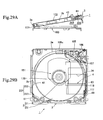
- the cartridge drop preventive means 221 is disposed on the first side surface plate 102b of the cartridge holder 102. As previously touched upon, when storage of the disk cartridge 1 in the cartridge holder 102 is completed, the protruded portion 223 disposed at the leading end portion of the cartridge drop preventive means 221 fits into the recessed portion 61 for releasing the first side pressure disposed in the first side surface 3b of the disk cartridge and is kept in a noncontact condition with respect to the first side surface 3b of the disk cartridge 1 as shown in Figs. 29A and 29B.
- the pair of right and left cartridge support portions 102d, 102e of the cartridge holder 102 includes a pair of positioning holes 118. Positioning pins 119 included in the chassis 103 to be described next are inserted in these positioning holes 118.
- the first and second side surface plates 102b, 102c of the cartridge holder 102 include bearing holes 121, 122 disposed on an end portion on a side opposite to the cartridge insertion port.
- the bearing holes 121, 122 serve the purpose of mounting the cartridge holder 102 rotatably in the chassis 103 to be described next.
- the chassis 103 is formed substantially into a rectangle from a metal plate.
- the chassis 103 includes damper mounting portions 131 disposed at four corners thereof. Rubber dampers 132 are fitted in these damper mounting portions 131.
- the chassis 103 includes right and left side walls 133, 134 located outside the first and second side surface plates 102b, 102c, respectively, of the cartridge holder 102.
- the side walls 133, 134 include a pair of bearing portions 135, 136 for rotatably mounting the cartridge holder 102.
- the bearing portions 135, 136 are located on the side of one end of the side walls 133, 134.
- Shafts 137 disposed on inner surfaces of the bearing portions 135, 136 are inserted into the bearing holes 121, 122 in the cartridge holder 102.
- the cartridge holder 102 is thereby supported rotatably between the cartridge insertion/removal position and the recording/reproducing position.
- the chassis 103 includes the positioning pins 120 that fit into the positioning holes 119 included in the right and left cartridge support portions 102d, 102e of the cartridge holder 102 when the cartridge holder 102 is moved to the recording/reproducing position.
- the recording and/or reproducing means 104 includes a spindle motor 151, the optical pickup 152, and a sled motor 153.
- the spindle motor 151 rotates the disk-shaped recording medium 2 of the disk cartridge 1.
- the optical pickup 152 records and/or reproduces information to and from the disk-shaped recording medium 2.
- the sled motor 153 drives the optical pickup 152.
- the spindle motor 151 includes a stator board 161, a bearing portion 161a, a bearing 162, a wiring board 164, an iron core coil 165, and a rotor assembly 167.
- the stator board 161 is a synthetic resin outsert-molded in a stator board forming hole 141 for the spindle motor (hereinafter referred to as a first stator board forming hole) disposed in the chassis 103.
- the bearing portion 161a is a tubular element integrally molded on an upper surface of the stator board 161.
- the bearing 162 is mounted in an inner periphery of the bearing portion 161a.
- the wiring board 164 is placed and held on the stator board 161 with the tubular bearing portion 161a inserted in a central hole 163.
- the iron core coil 165 is mounted on an outer peripheral portion of the tubular bearing portion 161a.
- the rotor assembly 167 is rotatably mounted with a leading end of a rotational central shaft 166 inserted in the bearing 162.
- a rotor magnet 168 paired with the iron core coil 165 is mounted on an inner peripheral surface of the rotor assembly 167.
- a disk table 170 is mounted on an upper surface of the rotor assembly 167. The disk table 170 uses a magnet 169 for magnetically clamping the hub 22 of the disk-shaped recording medium 2.
- the optical pickup 152 includes an objective lens driving apparatus 171 and a carrier rack 172.
- the carrier rack 172 moves the objective lens driving apparatus 171 in a radial direction of the disk-shaped recording medium 2 of the disk-shaped recording medium 2.
- the carrier rack 172 includes a first bearing portion 173 and a second bearing portion 174.
- the first bearing portion 173 is mounted with a lead screw 175.
- the second bearing portion 174 includes a guide portion 176.
- the lead screw 174 is rotatably supported by a pair of bearings 177 on the side of a lower surface of the chassis 103.
- the guide portion 176 is integrally formed with the chassis 103 through outsert molding.
- a worm gear 181 is mounted on one end of the lead screw 175. Referring to Fig. 2, the worm gear 181 is in mesh with a third gear 183 rotatably mounted through a shaft 182 on the lower surface of the chassis 103.
- the third gear 183 includes a second gear 184 disposed on a lower end portion thereof and mounted coaxially therewith.
- the second gear 184 has a larger diameter than the third gear 183.
- the second gear 184 is rotatably driven by the sled motor 153 through a first gear 185 to be described next.
- the sled motor 153 includes a stator board 191, a bearing portion 191a, a bearing 192, a wiring board 194, an iron core coil 195, and a rotor assembly 197.
- the stator board 191 is a synthetic resin outsert-molded in a stator board forming hole for the sled motor (hereinafter referred to as a second stator board forming hole) provided in the chassis 103.
- the bearing portion 191a is a tubular element integrally molded on an upper surface of the stator board 191.
- the bearing 192 is mounted in an inner periphery of the bearing portion 191a.
- the wiring board 194 is placed and held on the stator board 191 with the tubular bearing portion 191a inserted in a central hole 193.
- the iron core coil 195 is mounted on an outer peripheral portion of the tubular bearing portion 191a.
- the rotor assembly 197 is rotatably mounted with a leading end of a rotational central shaft 196 inserted in the bearing 192.
- a rotor magnet 198 paired with the iron core coil 195 is mounted on an inner peripheral surface of the rotor assembly 167.
- the first gear 185 is mounted on the lower surface of the rotor assembly.
- the eject lever 105 When the disk cartridge 1 is inserted, the eject lever 105 is pushed by the front surface 3a of the cartridge main body 3, rotating by counteracting the urging force of the urge means 106 to be described next. The eject lever 105 is then locked by the eject lever lock means 107 to be described later so as not to be rotated backward. After recording and/or reproducing has been completed, the lock release means 108 described earlier releases locking of the eject lever 105 by the eject lever lock means 107. This causes the eject lever 105 to be rotated backward by the urging force of the urge means 106, which unloads the disk cartridge 1 from the cartridge holder 102.
- the eject lever 105 includes a substantially V-shaped flat plate-like main portion 105a, a pressed portion 105c, a bearing hole 105d, and an operated portion 105e.
- the flat plate-like main portion 105a is to be overlapped with the upper surface of the chassis 103.
- the pressed portion 105c is disposed on the side of one end of the flat plate-like main portion 105a via an arm portion 105b.
- the pressed portion 105c is pressed by the front surface 3a of the cartridge main body 3.
- the bearing hole 105d is disposed on the side of the other end of the flat plate-like main portion 105a.
- the operated portion 105e is disposed at a position substantially symmetrical with respect to the pressed portion 105c across the bearing hole 105d.
- the operated portion 105e is operated for releasing locking by the eject lever operating portion 108d of the lock release means 108.
- the eject lever 105 is mounted on the upper surface of the chassis 103 rotatably by a shaft 105f. A central portion of the front surface 3a of the cartridge main body 3 of the disk cartridge 1 inserted into the cartridge holder 102 is to abut against the pressed portion 105c. In addition, the eject lever 105 is mounted on the upper surface of the chassis 103 such that the flat plate-like main portion 105a is raised by the shaft 105f to a position, at which locking by the eject lever lock means 107 can be released.
- the eject lever 105 is constructed as described in the foregoing.
- the front surface 3a of the cartridge main body 3 presses the pressed portion 105c, causing the eject lever 105 to counteract the urging force of the urge means 106 to be described next and rotate as shown in Fig. 21.
- the eject lever lock means 107 to be described next engages an outer side surface 105j of the pressed portion 105e, thus locking the eject lever 105 so as not to be rotated backward as shown in Fig. 22.
- the cartridge holder 102 is kept in a condition of not being able to rotate backward even if the cartridge holder 102 is rotated to the recording/reproducing position.
- the lock release means 108 releases locking of the eject lever 105 by the eject lever lock means 107 as shown in Figs. 8A, 8B, and 8C. Accordingly, the eject lever 105 is rotated backward by the urging force of the urge means 106, thus unloading the disk cartridge 1 from the cartridge holder 102.
- the urge means 106 gives the eject lever 105 a rotational force in the disk cartridge unloading direction.
- the urge means 106 also gives an urging force to pull the eject lever 105 in a direction of approaching the chassis 103.
- a coil spring is used for the urge means 106.
- the urge means 106 is disposed on the side of the lower surface of the chassis 103.
- One end of the urge means 106 is hooked onto a first spring latch portion 201 disposed in the chassis 103.
- the other end of the urge means 106 is hooked onto a second spring latch portion 202 disposed in the eject lever 105.
- the second spring latch portion 202 protrudes downwardly to the side of the lower surface of the chassis 103 through a cutout hole portion 203 included in the chassis 103.
- the eject lever lock means 107 engages the outer side surface 105j of the flat plate-like main portion 105a of the eject lever 105, thus locking the eject lever 105 so as not to be rotated backward.
- the eject lever lock means 107 is formed by disposing a boss-shaped protruded portion on the upper surface of the chassis 103.
- the eject lever lock means 107 is designed to be disengaged from the outer side surface 105j.
- the eject lever 105 as disengaged from the eject lever lock means 107, rotates with the flat plate-like main portion 105a thereof riding on the eject lever lock means 107.
- the disk cartridge 1 is thereby unloaded from the cartridge holder 102.
- the lock release means 108 functions to bring the outer side surface 105j of the flat plate-like main portion 105a of the eject lever 105 into a position, in which the outer side surface 105j is lifted off the chassis 103, by overcoming the urging force of the urge means 106.
- the lock release means 108 is formed from a flat spring separately from the cartridge holder 102.
- the lock release means 108 is mounted to the cartridge holder 102.
- the lock release means 108 includes the mounting portion (an immovably attaching portion) 108a, the overlapping portion 108b, the elastic flap portion 108c, and the eject lever operating portion 108d. More specifically, the mounting portion 108a is secured (immovably attached) to a side surface of the cartridge holder 102.
- the overlapping portion 108b continues from the mounting portion 108a in a condition bent substantially at a right angle therewith and overlaps an upper surface of the lock release means mounting portion 102h formed by indenting the upper surface 102a of the cartridge holder 102.
- the elastic flap portion 108c continues continues from the overlapping portion 108b in a condition bent at an acute angle ⁇ 1 (approximately 80°) relative thereto.
- the elastic flap portion 108c then enters the cartridge holder 102 through a cutout window portion 102i provided in the upper surface 102a of the cartridge holder 102 and extends toward the side of the chassis 103.
- the eject lever operating portion 108d continues from the elastic flap portion 108c in a condition bent at an obtuse angle ⁇ 2 (approximately 160°) relative thereto.
- the eject lever operating portion 108d includes an inclined surface portion 108e and an engagement portion 108f.
- the inclined surface portion 108e is pressed by a side surface 105m of the operated portion 105e of the eject lever 105 to be described later in detail so as to deflect the elastic flap portion 108c.
- the engagement portion 108f engages a lower surface 105n of the operated portion 105e when the elastic flap portion 108c makes a return motion as the inclined surface portion 108e is released from pressure by the side surface 105m of the operated portion 105e.
- the elastic flap portion 186c is what is called preloaded by being bent at substantially a right angle by being pressed by an elastic flap positioning portion 102j disposed on a lower surface of the lock release means mounting portion 102h.
- the elastic flap portion is also positioned at a predefined position.
- the lock release means 108 is formed by bending a flat spring stock blanked to a predetermined shape.
- the eject lever operating portion 108d is moved in an escaping direction (the direction of an arrow A) when the cartridge holder 102 is moved from the cartridge insertion/removal position to the recording/reproducing position.
- the inclined surface portion 108e is pressed by the side surface 105m of the operated portion 105e of the eject lever 105 to be described in detail later.
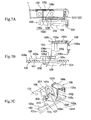
- Figs. 7A through 7C When the cartridge holder 102 moves to the cartridge recording/reproducing position, the pressure on the inclined surface portion 108e by the side surface 105m of the operated portion 105e is released, causing the elastic flap portion 108c to make a return motion, that is, to return elastically.
- the engagement portion 108f then engages the lower surface 105n of the operated portion 105e.
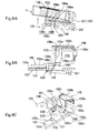
- the operation of moving the cartridge holder 102 from the cartridge insertion/removal position to the recording/reproducing position after recording and/or reproducing has been completed is performed as follows. Specifically, referring to Figs. 8A through 8C, the eject lever 105 is raised via the lower surface 105n of the operated portion 105e of the eject lever 105, leaving an upper surface of the chassis 103. Locking of the eject lever 105 by the eject lever lock means 107 is then released. The eject lever 105 is now rotated by the urging force of the urge means 106, pushing the disk cartridge 1 out of the cartridge holder 102.
- the lock release means 108 is disposed in an idle space as a substantially triangular dead space formed by the arcuate front surface 3a of the cartridge main body 3 of the disk cartridge 1 inserted in the cartridge holder 102, and one side surface and a front surface of the cartridge holder 102.
- the cartridge holder 102 is rotatably mounted to the chassis 103. When the cartridge holder 102 is rotationally moved from the cartridge insertion/removal position to the recording/reproducing position, locking of the eject lever 105 by the eject lever lock means 107 is released.
- the eject lever 105 is designed to be rotationally moved. An arrangement may nonetheless be possible, in which the eject lever 105 makes a linear motion.
- Figs. 23 through 25 are views showing an electronic apparatus 301, such as a gaming machine or the like, mounted with the disk recording and/or reproducing apparatus 101 according to the present invention.
- the electronic apparatus 301 is formed into a flat, horizontally long rectangle.
- a display portion 303 such as liquid crystal or the like, is disposed at a central portion on the side of a front surface 302a of an outer housing 302 of the electronic apparatus 301.
- a plurality of control keys 304 is disposed on both sides of the electronic apparatus 301.
- a lid portion 305 that can be rotatably opened or closed is disposed at a central portion on the side of a back surface 302b of the outer housing 302 of the electronic apparatus 301.
- the cartridge holder 102 of the disk recording and/or reproducing apparatus 101 is mounted on the lid portion 305.
- the chassis 103 of the disk recording and/or reproducing apparatus 101 is mounted on the side of the outer housing 302. It is designed that opening the lid portion 305 will rotate and bring the cartridge holder 102 to the cartridge insertion/removal position.
- the cartridge holder 102 follows the movement of the lid portion 305 to be rotated and moved to the cartridge insertion/removal position.
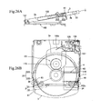
- the disk cartridge 1 is inserted into the cartridge holder 102 positioned at the cartridge insertion/removal position as shown in Figs. 26A and 26B.
- the protruded portion 223 of the cartridge drop preventive means 221 makes a sliding contact with the first side surface 3b of the cartridge main body 3 of the disk cartridge 1.
- the protruded portion 117 at the leading end of the shutter lock release member 116 makes a sliding contact with the outer surface of the first movement guide flap 49 of the shutter member 4. A substantially even side pressure is thus applied to the first side surface 3b and the second side surface 3c of the cartridge main body 3 of the disk cartridge 1.
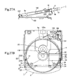
- the protruded portion 117 of the shutter lock release member 116 fits into the opening portion 48 for pressing operation disposed in the first movement guide flap 49 as shown in Figs. 27A and 27B.
- the protruded portion 117 of the shutter lock release member 116 thereby presses the pressed portion 57 of the shutter movement restriction member 5 of the disk cartridge 1, thus unlocking the shutter member 4.
- a shutter movement inhibiting protruded portion 63 disposed on an inner surface of the second side surface plate 102c of the cartridge holder 102 abuts against one end portion of the shutter member 4, thus inhibiting the shutter member 4 from moving.
- the protruded portion 223 of the cartridge drop preventive means 221 disposed in the cartridge holder 102 fits in the function enhancement groove 41 included in the disk cartridge.
- the cartridge main body 3 When the disk cartridge 1 is further inserted, the cartridge main body 3 only is inserted into the cartridge holder 102 with the shutter member 4 remaining stationary, thus opening the recording and/or reproducing opening portion 34 of the disk cartridge 1. In the meantime, the eject lever 105 is pressed and rotated allowing the urge means 106 to accumulate the urging force.
- the eject lever 105 When the disk cartridge 1 is entirely accommodated in the cartridge holder 102, the eject lever 105 is locked to be incapable of rotating backward by the eject lever lock means 107.
- the protruded portion 223 of the cartridge drop preventive means 221 fits into the recessed portion 61 for releasing the first side pressure disposed in the first side surface 3b of the cartridge main body 3 of the disk cartridge 1, thereby releasing the side pressure.
- the cartridge holder 102 is then moved from the cartridge insertion/removal position to the recording/reproducing position for performing recording and/or reproducing.
- the cartridge holder 102 is moved from the cartridge insertion/removal position to the recording/reproducing position as follows. Specifically, the side surface 105m of the operated portion 105e of the eject lever 105 contacts the inclined surface portion 108e of the lock release means 108, causing the elastic flap portion 108c to flex in what is called an escaping direction.
- an end portion of the inclined surface portion 108e moves to the position of the operated portion 105e of the eject lever 105, the contact between the inclined surface portion 108e and the side surface 105m of the operated portion 105e of the eject lever 105 is released.
- the elastic flap portion 108c then returns elastically and the engagement portion 108f engages the lower surface 105n of the operated portion 105e of the eject lever 105.
- the engagement portion 108f raises the lower surface 105n of the operated portion 105e of the eject lever 105, thus releasing locking of the eject lever 105 by the eject lever lock means 107.
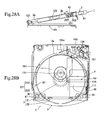
- the disk cartridge 1 is ejected out of the cartridge holder 102 through the steps depicted in Figs. 29A and 29B, Figs. 28A and 28B, Figs. 27A and 27B, and Figs. 26A and 26B.
- the protruded portion 223 makes a sliding contact with the first side surface 3b. This sliding contact prevents the disk cartridge from being unloaded.
- the protruded portion 223 fits in the function enhancement groove 41 disposed in the first side surface 3b as shown in Figs. 27A and 27B. This fitting of the protruded portion 223 in the function enhancement groove 41 further prevents the disk cartridge from being unloaded.
- the protruded portion 223 of the cartridge drop preventive means 221 thereafter makes another sliding contact with the first side surface 3b of the cartridge main body 3 of the disk cartridge 1.
- the protruded portion 117 at the leading end of the shutter lock release member 116 makes a sliding contact with the outer surface of the first movement guide flap 49 of the shutter member 4.
- a substantially even side pressure (frictional resistance) is thus applied to the first side surface 3b and the second side surface 3c of the cartridge main body 3 of the disk cartridge 1. The disk cartridge 1 is thereby prevented from jumping out of the cartridge holder 102.
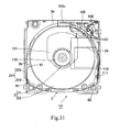
- the protruded portion 223 of the cartridge drop preventive means 221 makes a sliding contact with the first side surface 3b of the cartridge main body 3 of the disk cartridge 1A as shown in Fig. 30.
- the protruded portion 117 at the leading end of the shutter lock release member 116 makes a sliding contact with the second side surface 3c of the cartridge main body 3. A substantially even side pressure is thus applied to the first side surface 3b and the second side surface 3c of the cartridge main body 3 of the disk cartridge 1.
- the protruded portion 223 of the cartridge drop preventive means 221 fits into the recessed portion 61 for releasing the first side pressure disposed in the first side surface 3b of the cartridge main body 3 of the disk cartridge 1, thereby releasing the side pressure.
- the protruded portion 117 at the leading end of the shutter lock release member 116 fits into the recessed portion 62 for releasing the second side pressure disposed in the second side surface 3c of the cartridge main body 3, thus releasing the side pressure.
- Other operations are identical to the case of the disk cartridge 1 with the shutter and the same description is not repeated.
- a sliding resistance that is, a side pressure is applied during ejection to the first side surface of the disk cartridge using the cartridge drop preventive means, thereby preventing the disk cartridge from jumping out of the cartridge holder.
- the cartridge drop preventive means is formed to include the elastic flap portion and the protruded portion disposed at the leading end portion of the elastic flap portion. The protruded portion can therefore be pressed up against the first side surface of the disk cartridge with an adequate side pressure by the elastic flap portion.
- the protruded portion at of the shutter lock release member is kept in a noncontact condition with respect to the first side surface of the disk cartridge.
- the disk cartridge is thereby released from the side pressure of the cartridge drop preventive means.
- the cartridge drop preventive means is formed by cutting and raising the first side surface plate of the cartridge holder. This helps suppress an increase in the number of parts used.
Landscapes
- Feeding And Guiding Record Carriers (AREA)
Abstract
Description
- The present invention relates to a disk recording and/or reproducing apparatus including cartridge drop preventive means for preventing a disk cartridge from being dropped by momentum from a cartridge holder during ejection.
- There is known a disk apparatus having cartridge drop preventive means. The apparatus includes a pull plate that traverses a cartridge insertion path and is guided so as to be moved in parallel with a cartridge insertion direction. An inserted cartridge is abutted against the pull plate. The apparatus further includes a fitting holding member that fits elastically into recessed portions of the cartridge on both sides of the pull plate. The cartridge is held in position by this fitting holding member relative to the pull plate. During ejection, the pull plate is stopped at a predetermined position by a stopper. (See, for example,
Japanese Patent Laid-open No. 2001-189043 - Another known art is a disk cartridge that uses a spring to urge a shutter in a closing direction. The disk cartridge includes holding recessed portions disposed on a bottom surface of a case main body thereof. The holding recessed portions are engaged with, and held by, capturing bodies included in a disk drive. A closure reaction of the shutter spring during ejection operation is used to prevent the case main body from jumping out of a loading port of the disk drive. (See, for example,
Japanese Patent Laid-open No. 2000-173223 - The cartridge drop preventive means disclosed in
Japanese Patent Laid-open No. 2001-189043 - The cartridge drop preventive means disclosed in
Japanese Patent Laid-open No. 2000-173223 - It is an object of the present invention to provide a disk recording and/or reproducing apparatus including cartridge drop preventive means that is capable of positively preventing, with a simple structure, the disk cartridge from being dropped and without raising the problem of a raised disk cartridge or the like.
- The disk recording and/or reproducing apparatus, to which the present invention is applied, includes a cartridge holder, a chassis, recording and/or reproducing means, an eject lever, urge means, and cartridge drop preventive means. A disk cartridge is inserted in, and held by, the cartridge holder. The chassis supports the cartridge holder movably between a cartridge insertion/removal position and a recording/reproducing position. The recording and/or reproducing means is disposed in the chassis and records and/or reproduces the disk cartridge. The eject lever is disposed in the chassis movably in an insertion/removal direction of the disk cartridge and movably in a direction toward or away from the chassis. The eject lever is moved by being pushed by the disk cartridge inserted into the cartridge holder. The urge means gives the eject lever a moving force in a disk cartridge unloading direction and an urging force in a direction of approaching the chassis. The cartridge drop preventive means gives a braking force to the disk cartridge being unloaded by the urge means, thereby preventing the disk cartridge from dropping off from the cartridge holder.
- In the present invention, the cartridge drop preventive means is formed from a spring member disposed on a first side surface plate of the cartridge holder. The spring member makes a sliding contact with a first side surface of the disk cartridge during unloading of the disk cartridge so as to give the disk cartridge a braking force.
- In particular, the cartridge drop preventive means is formed to include an elastic flap portion and a protruded portion. The elastic flap portion extends toward a cartridge insertion port in the cartridge holder. The protruded portion is disposed on a leading end portion of the elastic flap portion and makes a sliding contact with the first side surface of the disk cartridge during unloading of the disk cartridge. Still another arrangement is made to keep the protruded portion disposed on the leading end of the elastic flap portion in a noncontact state relative to the first side surface of the disk cartridge when storage of the disk cartridge in the cartridge holder is completed.
- The cartridge drop preventive means is disposed on a first side surface plate opposing a second side surface plate of the cartridge holder, on which a shutter lock release member is disposed.
- Further, the cartridge drop preventive means is formed by cutting and raising the first side surface of the cartridge holder.
-
- Fig. 1 is a perspective view showing a disk recording and/or reproducing apparatus.
- Fig. 2 is a plan view showing the disk recording and/or reproducing apparatus as viewed from a backside.
- Fig. 3 is an exploded perspective view showing the disk recording and/or reproducing apparatus.
- Fig. 4 is a perspective view showing lock release means.
- Fig. 5 is a cross-sectional view showing the lock release means in its mounted condition.
- Fig. 6A is a side elevational view showing a condition, in which a side surface of an operated portion of an eject lever contacts an inclined surface portion of the lock release means; Fig. 6B is a front view showing the same; and Fig. 6C is a perspective view showing the same.
- Fig. 7A is a side elevational view showing a condition, in which an elastic flap portion elastically returns to cause an engagement portion to be engaged with a lower surface of the operated portion of the eject lever; Fig. 7B is a front view showing the same; and Fig. 7C is a perspective view showing the same.
- Fig. 8A is a side elevational view showing a condition, in which the engagement portion raises the lower surface of the operated portion of the eject lever and locking of the eject lever by eject lever lock means is thereby released; Fig. 8B is a front view showing the same; and Fig. 8C is a perspective view showing the same.
- Fig. 9 is a perspective view showing a disk cartridge (wherein a shutter is closed).
- Fig. 10 is a perspective view showing the disk cartridge as viewed from a backside thereof (wherein the shutter is closed).
- Fig. 11 is a perspective view showing the disk cartridge as viewed from the backside thereof (wherein the shutter is open).
- Fig. 12 is a plan view showing a condition, in which the shutter is locked.
- Fig. 13 is a plan view showing a principal part in a condition, in which the shutter is unlocked.
- Fig. 14 is an exploded perspective view showing a condition before the shutter is installed.
- Fig. 15 is a perspective view showing a condition, in which a shutter movement restriction member is mounted on the shutter.
- Fig. 16 is a cross-sectional view showing a condition, in which the shutter is installed.
- Fig. 17 is a perspective view showing a disk cartridge not including a shutter.
- Fig. 18 is an exploded cross-sectional view showing a spindle motor.
- Fig. 19 is an exploded cross-sectional view showing a sled motor.
- Fig. 20 is a side elevation view showing a condition, in which a cartridge holder is placed at a cartridge insertion/removal position.
- Fig. 21 is a plan view showing a condition before the eject lever is pushed.
- Fig. 22 is a plan view showing a condition after the eject lever is pushed.
- Fig. 23 is a perspective view showing an electronic apparatus.
- Fig. 24 is a perspective view showing the electronic apparatus as viewed from a backside thereof.
- Fig. 25 is a perspective view showing a condition, in which a lid portion is open.
- Fig. 26A is a side elevational view showing an operation when a disk cartridge including a shutter is used; and Fig. 26B is a plan view showing the same.
- Fig. 27A is a side elevational view showing an operation when a disk cartridge including a shutter is used; and Fig. 27B is a plan view showing the same.
- Fig. 28A is a side elevational view showing an operation when a disk cartridge including a shutter is used; and Fig. 28B is a plan view showing the same.
- Fig. 29A is a side elevational view showing an operation when a disk cartridge including a shutter is used; and Fig. 29B is a plan view showing the same.
- Fig. 30 is a plan view showing an operation when a disk cartridge having no shutter is used.
- Fig. 31 is a plan view showing an operation when a disk cartridge having no shutter is used.
- A disk recording and/or reproducing apparatus to which the present invention is applied will be described below in the following order: (1) General construction of the apparatus and construction of the cartridge drop preventive means; (2) Construction of the disk cartridge; (3) Construction of the cartridge holder; (4) Construction of the chassis; (5) Construction of the recording and/or reproducing means; (6) Construction of the eject lever; (7) Construction of the urge means and the eject lever lock means; (8) Construction of the lock release means; (9) Other arrangements; and (10) Operation.
- Fig. 1 is a perspective view showing the disk recording and/or reproducing apparatus, to which the present invention is applied. Fig. 2 is a plan view as viewed from a backside. Fig. 3 is an exploded perspective view. A disk recording and/or reproducing
apparatus 101 includes acartridge holder 102, achassis 103, recording and/or reproducingmeans 104, aneject lever 105, urge means 106, eject lever lock means 107, lock release means 108, and cartridge droppreventive means 221. Adisk cartridge 1 is inserted in, and held by, thecartridge holder 102. Thechassis 103 supports thecartridge holder 102 movably between a cartridge insertion/removal position and a recording/reproducing position. The recording and/or reproducingmeans 104 is disposed in thechassis 103 and records and/or reproduces thedisk cartridge 1. Theeject lever 105 is disposed in thechassis 103 rotationally movably (hereinafter referred to simply as "rotatably") in an insertion/removal direction of thedisk cartridge 1 and movably in a direction toward or away from thechassis 103. Theeject lever 105 is rotated by being pushed by thedisk cartridge 1 inserted into thecartridge holder 102. The urge means 106 gives theeject lever 105 a rotational force in a disk cartridge unloading direction and an urging force in a direction of approaching thechassis 103. The eject lever lock means 107 locks theeject lever 105, which has been rotated by the insertion of thedisk cartridge 1, onto thechassis 103. The lock release means 108 releases a lock of theeject lever 105 by the eject lever lock means 107 when thecartridge holder 102 is rotated from the recording/reproducing position to the cartridge insertion/removal position. - The cartridge drop preventive means 221 is formed from a flat spring member disposed on a first
side surface plate 102b of thecartridge holder 102. The flat spring member makes a sliding contact with afirst side surface 3b of thedisk cartridge 102 during unloading of the disk cartridge so as to give the disk cartridge 1 a braking force. - The cartridge drop preventive means 221 includes an
elastic flap portion 222 and a protrudedportion 223. Theelastic flap portion 222 extends toward acartridge insertion port 102k in thecartridge holder 102. The protrudedportion 223 is disposed on a leading end portion of theelastic flap portion 222 and contacts thefirst side surface 3b of thedisk cartridge 1 during unloading of the disk cartridge. - Referring to Figs. 29A and 29B, the protruded
portion 223 fits into a recessedportion 61 disposed in thefirst side surface 3b of thedisk cartridge 1 for releasing a first side pressure and is kept in a noncontact condition with respect to thefirst side surface 3b when storage of thedisk cartridge 1 in thecartridge holder 102 is completed. - A second
side surface plate 102c opposing the firstside surface plate 102b of thecartridge holder 102 including the cartridge drop preventive means 221 includes a shutterlock release member 116. - The cartridge drop preventive means 221 is formed by cutting and raising the first
side surface plate 102b of thecartridge holder 102, or by providing a window portion in the firstside surface plate 102b of thecartridge holder 102 and the attaching the cartridge drop preventive means 221 made of a flat spring so as to face the window portion. - Fig. 9 is a perspective view showing the
disk cartridge 1 as viewed from an upper half side. Fig. 10 is a perspective view showing thedisk cartridge 1 as viewed from a lower half side. Fig. 11 is a perspective view showing a condition, in which a shutter member is slid to expose an opening portion for recording and/or reproducing. - The
disk cartridge 1 includes a disk-shapedrecording medium 2, a cartridgemain body 3, ashutter member 4, a shuttermovement restriction member 5, anurge member 6, and a deformationpreventive portion 7. The cartridgemain body 3 accommodates the disk-shapedrecording medium 2 rotatably within a circular disk storage portion and includes a recording and/or reproducingopening portion 34 that allows part of the disk-shapedrecording medium 2 to face an outside. Theshutter member 4 is mounted in the cartridgemain body 3 movably between a position of closing the recording and/or reproducingopening portion 34 and a position of opening the recording and/or reproducingopening portion 34. The shutter movement restriction member 5 (see Fig. 14) restricts theshutter member 4 from moving in a direction of opening the recording and/or reproducingopening portion 34 by being engaged with amovement restriction portion 3e disposed in the cartridgemain body 3 when theshutter member 4 is located at the position of closing the recording and/or reproducingopening portion 34. Theurge member 6 urges the shuttermovement restriction member 5 in a direction of being engaged with themovement restriction portion 3e disposed in the cartridgemain body 3. The deformationpreventive portion 7 prevents theurge member 6 from being deformed by an external force. - The
urge member 6 includes anextension flap 6a and anelastic displacement flap 6c. Theextension flap 6a is extended from one side of theshutter member 4. Theelastic displacement flap 6c is formed by folding back theextension flap 6a via a fold backportion 6b disposed at a leading end portion of theextension flap 6a so as to overlap an inside of theextension flap 6a. - The deformation
preventive portion 7 is disposed on a back of the leading end portion of theurge member 6. The deformationpreventive portion 7 supports theurge member 6 from the back, thereby preventing theurge member 6 from being deformed by an external force. - Referring to Fig. 12, in a condition, in which the
shutter member 4 closes the recording and/or reproducingopening portion 34, theurge member 6 makes a leading end portion of theelastic displacement flap 6c press a pressedportion 57 disposed on the side of one end of the shuttermovement restriction member 5. Theurge member 6 thereby rotates the shuttermovement restriction member 5 about a mountingshaft 8 in a clockwise direction. Anengagement portion 58 disposed on the side of the other end of the shuttermovement restriction member 5 is thus located at an engageable position relative to themovement restriction portion 3e disposed in the cartridgemain body 3. When it is attempted in this condition to move theshutter member 4 in the direction of opening the recording and/or reproducingopening portion 34, theengagement portion 58 disposed on the side of the other end of the shuttermovement restriction member 5 is engaged with themovement restriction portion 3e disposed in the cartridgemain body 3, thereby preventing theshutter member 4 from moving. When the pressedportion 57 is pressed, in opposition to an urging force of theelastic displacement flap 6c, by a protrudedportion 117 of the shutterlock release member 116 disposed on the secondside surface plate 102c of thecartridge holder 102 to be described next, the shuttermovement restriction member 5 rotates about the mountingshaft 8 in a counterclockwise direction as shown in Fig. 13. Theengagement portion 58 is thereby escaped to a position, at which engagement with themovement restriction portion 3e is disabled. Theshutter member 4 is thus allowed to move in the direction of opening the recording and/or reproducingopening portion 34. - Each of the disk-shaped
recording medium 2, the cartridgemain body 3, theshutter member 4, the shuttermovement restriction member 5, theurge member 6, and the deformationpreventive portion 7 will be described in detail. - Referring to Fig. 9, the disk-shaped
recording medium 2 is formed by mounting a chuckinghub 22 at a center of anoptical disk 21 on which gaming software or the like is recorded. Theoptical disk 21 is formed to have a small diameter of about 50 mm. The chuckinghub 22 is formed from a stainless steel or other magnetic metal attracted by a magnet. - The cartridge
main body 3 is formed by makingperipheral walls lower halves arcuate ribs peripheral walls - Reference is made to Fig. 11. The cartridge
main body 3 includes afront surface 3a (a side surface on the side of an insertion end to the disk recording and/or reproducing apparatus to be described later), right and left side surfaces (hereinafter referred to as first and second side surfaces) 3b, 3c, and aback surface 3d. Thefront surface 3a is formed into an arcuate surface (a semicircular surface) having substantially the same radius of curvature as theoptical disk 21. The first andsecond side surfaces front surface 3a, are formed into flat surfaces that run in parallel with each other. Theback surface 3d opposing thefront surface 3a and continuing to the first andsecond side surfaces - The
lower half 32 includes adriving opening portion 33 disposed at a center thereof. The drivingopening portion 33 allows thehub 22 of the disk-shapedrecording medium 2 to face the outside. Thelower half 32 also includes the recording and/or reproducingopening portion 34 disposed over an area covering from a point near thedriving opening portion 33 to thesecond side surface 3c. The recording and/or reproducingopening portion 34 allows an information recording surface of theoptical disk 21 to face the outside. - The
hub 22 of the disk-shapedrecording medium 2 is magnetically clamped onto a disk table 170 of the disk recording and/or reproducingapparatus 101 via thedriving opening portion 33. Anoptical pickup 152 of the disk recording and/or reproducingapparatus 101 records and/or reproduces information relative to theoptical disk 21 of the disk-shapedrecording medium 2 via the recording and/or reproducingopening portion 34. - The
disk cartridge 1 also includes a recessed step portion (hereinafter referred to as a first dent portion) 35 disposed in an area covering from anouter surface 32c of thelower half 32 to the peripheral wall of thesecond side surface 3c. Thefirst dent portion 35 has the following functions. Specifically, thefirst dent portion 35 ensures that theshutter member 4 to be described next is mounted so as not to protrude from theouter surface 32b of thelower half 32 and thesecond side surface 3c; or more specifically, thefirst dent portion 35 ensures that theshutter member 4 is mounted flush with theouter surface 32c of thelower half 32 and an outer surface of the peripheral wall on the side of thesecond side surface 3c. Further, thefirst dent portion 35 restricts a movement range of theshutter member 4. - An end portion of the
first dent portion 35 on the side of thedriving opening portion 33 is formed as asecond dent portion 36 that is even deeper than thefirst dent portion 35. A foldedportion 44a disposed at a leading end of an opening open/close portion 44 of theshutter member 4 to be described next is inserted into thesecond dent portion 36. Thesecond dent portion 36 is closed at a position upward of the folded portion 4a by ashutter guide plate 37 mounted to thelower half 32. Further, theshutter guide plate 37 prevents the foldedportion 44a at the leading end of the opening open/close portion 44 from curving upward. Theshutter guide plate 37 is also mounted in thelower half 32 in a condition, in which theshutter guide plate 37 remains flush with the outer surface of thelower half 32. - Referring to Fig. 14, the
upper half 31 includes aguide groove 38 that extends in a moving direction of theshutter member 4. Theguide groove 38 is disposed in theperipheral wall 31a on the side of thesecond side surface 3c. In addition, theperipheral wall 32a on the side of thesecond side surface 3c of thelower half 32 is removed. This arrangement forms an openingportion 39 for shutter member guiding in a space formed with theperipheral wall 31a on the side of thesecond side surface 3c of theupper half 31. - Further, an area from the
second side surface 3c to thefront surface 3a of the cartridgemain body 3 includes a shutter lock releasemember guide groove 40. The shutter lock releasemember guide groove 40 continues into the openingportion 39 for shutter member guiding. In addition, the other side surface of the cartridgemain body 3, that is, thefirst side surface 3b includes afunction enhancement groove 41 and the side pressure releasing recessedportion 61. The side pressure releasing recessedportion 61 functions as follows. Specifically, when storage of thedisk cartridge 1 in thecartridge holder 102 is completed, the protrudedportion 223 of the cartridge drop preventive means 221 fits into the recessedportion 61 and is kept in a noncontact condition with respect to thefirst side surface 3b of the cartridgemain body 3. The side pressure releasing recessedportion 61 thereby releases a side pressure by the cartridge drop preventive means 221 on thecartridge holder 102. - Referring to Fig. 11, an outer surface of the
lower half 32 on the side of thefront surface 3a includes a pair of positioning holes 42, 43. - Referring to Fig. 14, the
shutter member 4 includes the flat plate-like opening open/close portion 44 and anassembly portion 45. The opening open/close portion 44 closes the recording and/or reproducingopening portion 34. Theassembly portion 45 is used for assembling theshutter member 4 to the cartridgemain body 3 so that theshutter member 4 is movable between the position of opening the recording and/or reproducingopening portion 34 and the position of closing the recording and/or reproducingopening portion 34 with the opening open/close portion 44 overlapped with thefirst dent portion 35 of thelower half 32. - The
assembly portion 45 includes a firstmovement guide flap 46 and a secondmovement guide flap 47. The firstmovement guide flap 46 is formed by bending the side of one end of the opening open/close portion 44 substantially at a right angle. The secondmovement guide flap 47 is formed by bending a leading end portion of the firstmovement guide flap 46 substantially at a right angle so as to run in the same direction as the opening open/close portion 44. - The first
movement guide flap 46 includes an openingportion 48 for pressing operation at a central portion thereof. The pressedportion 57 of the shuttermovement restriction member 5 to be next described in detail faces this openingportion 48. The firstmovement guide flap 46 also includes third and fourth movement guide flaps 49, 50 disposed on both sides in the shutter movement direction and at substantially a central portion in a thickness direction of the cartridgemain body 3. The third and fourth movement guide flaps 49, 50 run substantially in parallel with the secondmovement guide flap 47. The third and fourth movement guide flaps 49, 50 also includelock tabs lock tabs close portion 44. There is disposed a boss-shapedshaft portion 52 on a lower surface of the fourthmovement guide flap 50. Theshaft portion 52 allows the shuttermovement restriction member 5 to be mounted rotatably. An end portion of the opening open/close portion 44 opposite to theassembly portion 45 includes the foldedportion 44a for upward curving prevention. Theshutter member 4 is formed by bending a metal plate blanked to a predetermined shape. - Referring to Fig. 16, the
shutter member 4 is slidably mounted on the side of thesecond side surface 3c of the cartridgemain body 3 as detailed in the following. Specifically, the firstmovement guide flap 46 is aligned with the shutter Rick releasemember guide groove 40 in thesecond side surface 3c of the cartridgemain body 3. The secondmovement guide flap 47 is then inserted into theguide groove 38 included in theupper half 31. The third and fourth movement guide flaps 49, 50 are inserted into the cartridgemain body 3 through the openingportion 39 for guiding the shutter member. Thelock tab 51a disposed on the leading end of the thirdmovement guide flap 49 is then engaged with agroove 32e included in a bottom surface of theperipheral wall 31a of theupper half 31. Thelock tab 51b disposed on the leading end of the fourthmovement guide flap 50 is engaged with aninner surface 32f of theperipheral wall 31a of theupper half 31. - Referring to Fig. 10, when the
shutter member 4 is slid toward the side of thefront surface 3a of the cartridgemain body 3, the opening open/close portion 44 closes the recording and/or reproducingopening portion 34. Referring this time to Fig. 11, when theshutter member 4 is slid toward the side of thefront surface 3a of the cartridgemain body 3, the opening open/close portion 44 opens the recording and/or reproducingopening portion 34. - Reference is now made to Figs. 14 and 15. The shutter
movement restriction member 5 includes a flat plate-likemain body portion 56, the pressedportion 57, and theengagement portion 58. Themain body portion 56 includes abearing hole 55 located at a central portion thereof. The pressedportion 57 is located at one end portion of themain body portion 56. Theengagement portion 58 is located at the other end portion of themain body portion 56. The shuttermovement restriction member 5 further includes a protrudedportion 59 for inhibiting rotation disposed on the end portion thereof, in which the pressedportion 57 of themain body 56 is provided. The pressedportion 57 and theengagement portion 58 are formed by bending one end portion and the other end portion of themain body portion 56 substantially at a right angle in the same direction. The shuttermovement restriction member 5 is formed by bending a metal plate blanked to a predetermined shape. - The shutter
movement restriction member 5 is rotatably mounted in the fourthmovement guide flap 50 by inserting the boss-shapedshaft portion 52 on the fourthmovement guide flap 50 of theshutter member 4 in thebearing hole 55. When the shuttermovement restriction member 5 is rotated until the protrudedportion 59 for inhibiting rotation abuts on the inner surface of the firstmovement guide flap 46 of theshutter member 4, the pressedportion 56 faces the openingportion 48 for pressing operation disposed at the central portion of the firstmovement guide flap 46 of theshutter member 4 as shown in Fig. 11. At the same time, referring to Fig. 12, theengagement portion 58 becomes engageable with themovement restriction portion 3e disposed on the cartridgemain body 3, thus inhibiting theshutter member 4 from moving. - As described earlier, the
urge member 6 includes theextension flap 6a and theelastic displacement flap 6c. Theextension flap 6a is extended from one side of theshutter member 4. Theelastic displacement flap 6c is formed by folding back theextension flap 6a via the fold backportion 6b disposed at the leading end portion of theextension flap 6a. (See Fig. 14.) - The
extension flap 6a is formed by being curved so as to advance into the cartridgemain body 3 through the openingportion 39 for guiding the shutter member when theshutter member 4 is assembled in the cartridgemain body 3. Theelastic displacement flap 6c is folded back in a curved condition so as to overlap the inner surface of theextension flap 6c. The leading end portion of theelastic displacement flap 6c is to press the pressedportion 57 disposed on the side of one end of the shuttermovement restriction member 5, thus causing the pressedportion 57 to face the openingportion 48 for pressing operation disposed at the central portion of the firstmovement guide flap 46 of theshutter member 4. Theextension flap 6a makes theelastic displacement flap 6c long, thereby allowing spring constant of theurge member 6 to be adjusted. - Fig. 17 is a view showing a disk cartridge according to another embodiment of the present invention. According to this embodiment of the present invention, a
disk cartridge 1A adopts what is called a shutter-less structure having noshutter member 4. Theshutter-less disk cartridge 1A includes afunction enhancement groove 41 and a first side pressure releasing recessedportion 61. Thefunction enhancement groove 41 is disposed in afirst side surface 3b of a cartridgemain body 3. The side pressure releasing recessedportion 61 functions as follows. Specifically, when storage of thedisk cartridge 1 in acartridge holder 102 is completed, a protrudedportion 223 of a cartridge drop preventive means 221 fits into the recessedportion 61 and is kept in a noncontact condition with respect to thefirst side surface 3b of the cartridgemain body 3 of thedisk cartridge 1. The side pressure releasing recessedportion 61 thereby releases a side pressure by the cartridge drop preventive means 221 on thecartridge holder 102. It should be noted herein that thefunction enhancement groove 41 is formed closer to the side of an insertion end as compared with the first side pressure releasing recessedportion 61. In addition, asecond side surface 3c includes a second side pressure releasing recessedportion 62. The second side pressure releasing recessedportion 62 functions as follows. Specifically, when storage of thedisk cartridge 1 in thecartridge holder 102 is completed, a protrudedportion 117 at a leading end of a shutterlock release member 116 disposed on a secondside surface plate 102c of acartridge holder 102 to be described next fits into the recessedportion 62 and is kept in a noncontact condition with respect to thesecond side surface 3c of the cartridgemain body 3 of thedisk cartridge 1. The second side pressure releasing recessedportion 62 thereby removes a side pressure by the shutterlock release member 116 on thecartridge holder 102. This embodiment is identical to thedisk cartridge 1 including theshutter member 4 described heretofore in the rest of the structures and the same description is not repeated. - Referring to Fig. 3, the
cartridge holder 102 includes an upper surface plate (top surface plate) 102a, the right and left side surface plates (hereinafter referred to as the first and second side surface plates) 102b, 102c, a pair of right and leftcartridge support portions surface portions upper surface plate 102a is substantially a square. The first and secondside surface plates upper surface plate 102a downwardly substantially at a right angle. Thecartridge support portions side surface plates cartridge support portions disk cartridge 1 inserted in thecartridge holder 102. The receivingsurface portions cartridge support portions upper surface plate 102a, the first and secondside surface plates cartridge support portions insertion port 102k of thedisk cartridge 1 and a storage portion that continues thereto. Abridge plate 102m is attached at a position closer to the insertion port of the pair of right and leftcartridge support portions bridge plate 102m is attached so as to cross over thecartridge support portions bridge plate 102m serves as reinforcement for preventing the pair ofcartridge support portions bridge plate 102m also functions to prevent thedisk cartridge 1 from jumping out from a space between the pair ofcartridge support portions - The
upper surface plate 102a has ahexagonal opening portion 111 blanked at a center thereof. Theopening portion 111 is for reducing weight of thecartridge holder 102. - A pair of right and left, or first and second
flat springs opening portion 111. The first and secondflat springs insertion port 102k. The first and secondflat springs disk cartridge 1 inserted into the storage portion, thereby pressing thedisk cartridge 1 against thecartridge support portions flat springs opening portion 111. The third and fourthflat springs upper surface plate 102a. The third and fourthflat springs cartridge holder 102 relative to a cartridge holder storage portion or the like of an electronic apparatus. The first through fourthflat springs 112 to 115 are formed by blanking part of theupper surface plate 102a of thedisk cartridge 1. - The recessed lock release means mounting
portion 102h is formed in the following space. The space is specifically between the secondflat spring 113 and the secondside surface plate 102c of thecartridge holder 102, and between the arcuatefront surface 3a of thedisk cartridge 1 inserted in thecartridge holder 102 and the secondside surface plate 102c of thecartridge holder 102. The space is what is called a dead space. Referring to Fig. 5, two cylindrical boss-shapedprotrusions 102n are formed on the secondside surface plate 102c of thecartridge holder 102 facing the lock release means mountingportion 102h. The lock release means 108 is mounted through the following mounting steps in the substantially triangular dead space formed by thedisk cartridge 1 inserted in thecartridge holder 102, and the arcuatefront surface 3a and theside surface 3c of the cartridgemain body 3. Specifically, the boss-shapedprotrusions 102n are inserted in protrusionfitting holes 108g in the mountingportion 108a. An overlappingportion 108b is overlapped with the upper surface of the lock release means mountingportion 102h. Theelastic flap portion 108c and the ejectlever operating portion 108d are then inserted in thecartridge holder 102 and leading end portions of the boss-shapedprotrusions 102n are then caulked to enlarge diameters thereof. - As shown in Fig. 3, the second
side surface plate 102c of thecartridge holder 102 is mounted with the shutterlock release member 116 for releasing locking of theshutter member 4 by the shuttermovement restriction member 5 of thedisk cartridge 1. - The
lock release member 116 is formed from a flat spring. Like the mountingportion 108a of the lock release means 108, thelock release member 116 is immovably attached to the secondside surface plate 102c of thecartridge holder 102. The side on one end portion of thelock release member 116 in a length direction is secured by the boss-shapedprotrusions 102n disposed on the secondside surface plate 102c of thecartridge holder 102. Thelock release member 116 extends along the secondside surface plate 102c of thecartridge holder 102 up to a point near the cartridge insertion port. A protrudedportion 117 having substantially a V shape in a plan view is disposed on a leading end portion of thelock release member 116. The protrudedportion 117 advances into thecartridge holder 102 through acutout window 118 provided in the secondside surface plate 102c of thecartridge holder 102. Referring to Fig. 13, when thedisk cartridge 1 is inserted into thecartridge holder 102 a predetermined amount, the protrudedportion 117 at the leading end of the shutterRick release member 116 presses the pressedportion 57 of the shuttermovement restriction member 5, thus unlocking theshutter member 4. - The cartridge drop preventive means 221 is disposed on the first
side surface plate 102b of thecartridge holder 102. As previously touched upon, when storage of thedisk cartridge 1 in thecartridge holder 102 is completed, the protrudedportion 223 disposed at the leading end portion of the cartridge drop preventive means 221 fits into the recessedportion 61 for releasing the first side pressure disposed in thefirst side surface 3b of the disk cartridge and is kept in a noncontact condition with respect to thefirst side surface 3b of thedisk cartridge 1 as shown in Figs. 29A and 29B. - The pair of right and left
cartridge support portions cartridge holder 102 includes a pair of positioning holes 118. Positioning pins 119 included in thechassis 103 to be described next are inserted in these positioning holes 118. - The first and second
side surface plates cartridge holder 102 include bearingholes cartridge holder 102 rotatably in thechassis 103 to be described next. - The
chassis 103 is formed substantially into a rectangle from a metal plate. Thechassis 103 includesdamper mounting portions 131 disposed at four corners thereof.Rubber dampers 132 are fitted in thesedamper mounting portions 131. Thechassis 103 includes right and leftside walls side surface plates cartridge holder 102. Theside walls portions cartridge holder 102. The bearingportions side walls Shafts 137 disposed on inner surfaces of the bearingportions cartridge holder 102. Thecartridge holder 102 is thereby supported rotatably between the cartridge insertion/removal position and the recording/reproducing position. - The
chassis 103 includes the positioning pins 120 that fit into the positioning holes 119 included in the right and leftcartridge support portions cartridge holder 102 when thecartridge holder 102 is moved to the recording/reproducing position. - Referring to Fig. 3, the recording and/or reproducing
means 104 includes aspindle motor 151, theoptical pickup 152, and asled motor 153. Thespindle motor 151 rotates the disk-shapedrecording medium 2 of thedisk cartridge 1. Theoptical pickup 152 records and/or reproduces information to and from the disk-shapedrecording medium 2. Thesled motor 153 drives theoptical pickup 152. - Referring to Fig. 18, the
spindle motor 151 includes astator board 161, a bearingportion 161a, abearing 162, awiring board 164, aniron core coil 165, and arotor assembly 167. Thestator board 161 is a synthetic resin outsert-molded in a statorboard forming hole 141 for the spindle motor (hereinafter referred to as a first stator board forming hole) disposed in thechassis 103. The bearingportion 161a is a tubular element integrally molded on an upper surface of thestator board 161. Thebearing 162 is mounted in an inner periphery of the bearingportion 161a. Thewiring board 164 is placed and held on thestator board 161 with thetubular bearing portion 161a inserted in acentral hole 163. Theiron core coil 165 is mounted on an outer peripheral portion of thetubular bearing portion 161a. Therotor assembly 167 is rotatably mounted with a leading end of a rotationalcentral shaft 166 inserted in thebearing 162. Arotor magnet 168 paired with theiron core coil 165 is mounted on an inner peripheral surface of therotor assembly 167. A disk table 170 is mounted on an upper surface of therotor assembly 167. The disk table 170 uses amagnet 169 for magnetically clamping thehub 22 of the disk-shapedrecording medium 2. - Referring to Fig. 3, the
optical pickup 152 includes an objectivelens driving apparatus 171 and acarrier rack 172. Thecarrier rack 172 moves the objectivelens driving apparatus 171 in a radial direction of the disk-shapedrecording medium 2 of the disk-shapedrecording medium 2. - The
carrier rack 172 includes afirst bearing portion 173 and asecond bearing portion 174. Thefirst bearing portion 173 is mounted with alead screw 175. Thesecond bearing portion 174 includes aguide portion 176. - The
lead screw 174 is rotatably supported by a pair ofbearings 177 on the side of a lower surface of thechassis 103. Theguide portion 176 is integrally formed with thechassis 103 through outsert molding. - A
worm gear 181 is mounted on one end of thelead screw 175. Referring to Fig. 2, theworm gear 181 is in mesh with athird gear 183 rotatably mounted through ashaft 182 on the lower surface of thechassis 103. - The
third gear 183 includes asecond gear 184 disposed on a lower end portion thereof and mounted coaxially therewith. Thesecond gear 184 has a larger diameter than thethird gear 183. Thesecond gear 184 is rotatably driven by thesled motor 153 through afirst gear 185 to be described next. - Referring to Fig. 19, the
sled motor 153 includes astator board 191, a bearingportion 191a, abearing 192, awiring board 194, aniron core coil 195, and arotor assembly 197. Thestator board 191 is a synthetic resin outsert-molded in a stator board forming hole for the sled motor (hereinafter referred to as a second stator board forming hole) provided in thechassis 103. The bearingportion 191a is a tubular element integrally molded on an upper surface of thestator board 191. Thebearing 192 is mounted in an inner periphery of the bearingportion 191a. Thewiring board 194 is placed and held on thestator board 191 with thetubular bearing portion 191a inserted in acentral hole 193. Theiron core coil 195 is mounted on an outer peripheral portion of thetubular bearing portion 191a. Therotor assembly 197 is rotatably mounted with a leading end of a rotationalcentral shaft 196 inserted in thebearing 192. Arotor magnet 198 paired with theiron core coil 195 is mounted on an inner peripheral surface of therotor assembly 167. In addition, thefirst gear 185 is mounted on the lower surface of the rotor assembly. - Reference is now made to Fig. 2. When the
sled motor 153 rotates thelead screw 175 through thefirst gear 185, thesecond gear 184, thethird gear 183, and theworm gear 181, thecarrier rack 172 is guided by theguide portion 176 and moved in thepickup disposition hole 143. Thecarrier rack 172 thereby moves the objectivelens driving apparatus 171 in the radial direction of the disk-shapedrecording medium 2 of the disk-shapedrecording medium 2. - When the
disk cartridge 1 is inserted, theeject lever 105 is pushed by thefront surface 3a of the cartridgemain body 3, rotating by counteracting the urging force of the urge means 106 to be described next. Theeject lever 105 is then locked by the eject lever lock means 107 to be described later so as not to be rotated backward. After recording and/or reproducing has been completed, the lock release means 108 described earlier releases locking of theeject lever 105 by the eject lever lock means 107. This causes theeject lever 105 to be rotated backward by the urging force of the urge means 106, which unloads thedisk cartridge 1 from thecartridge holder 102. - Referring to Fig. 3, the
eject lever 105 includes a substantially V-shaped flat plate-likemain portion 105a, a pressedportion 105c, abearing hole 105d, and an operatedportion 105e. The flat plate-likemain portion 105a is to be overlapped with the upper surface of thechassis 103. The pressedportion 105c is disposed on the side of one end of the flat plate-likemain portion 105a via anarm portion 105b. The pressedportion 105c is pressed by thefront surface 3a of the cartridgemain body 3. Thebearing hole 105d is disposed on the side of the other end of the flat plate-likemain portion 105a. The operatedportion 105e is disposed at a position substantially symmetrical with respect to the pressedportion 105c across thebearing hole 105d. The operatedportion 105e is operated for releasing locking by the ejectlever operating portion 108d of the lock release means 108. - The
eject lever 105 is mounted on the upper surface of thechassis 103 rotatably by ashaft 105f. A central portion of thefront surface 3a of the cartridgemain body 3 of thedisk cartridge 1 inserted into thecartridge holder 102 is to abut against the pressedportion 105c. In addition, theeject lever 105 is mounted on the upper surface of thechassis 103 such that the flat plate-likemain portion 105a is raised by theshaft 105f to a position, at which locking by the eject lever lock means 107 can be released. - The
eject lever 105 is constructed as described in the foregoing. When thedisk cartridge 1 is inserted in thecartridge holder 102 in the cartridge insertion/removal position (in a condition, in which thecartridge holder 102 is inclined at a predetermined inclined angle θ relative to the chassis 103) as shown in Fig. 20, thefront surface 3a of the cartridgemain body 3 presses the pressedportion 105c, causing theeject lever 105 to counteract the urging force of the urge means 106 to be described next and rotate as shown in Fig. 21. When thedisk cartridge 1 is entirely accommodated in thecartridge holder 102, the eject lever lock means 107 to be described next engages anouter side surface 105j of the pressedportion 105e, thus locking theeject lever 105 so as not to be rotated backward as shown in Fig. 22. In this condition, thecartridge holder 102 is kept in a condition of not being able to rotate backward even if thecartridge holder 102 is rotated to the recording/reproducing position. When thecartridge holder 102 is rotated from the recording/reproducing position to the cartridge insertion/removal position after recording and/or reproducing has been completed, the lock release means 108 releases locking of theeject lever 105 by the eject lever lock means 107 as shown in Figs. 8A, 8B, and 8C. Accordingly, theeject lever 105 is rotated backward by the urging force of the urge means 106, thus unloading thedisk cartridge 1 from thecartridge holder 102. - The urge means 106 gives the
eject lever 105 a rotational force in the disk cartridge unloading direction. The urge means 106 also gives an urging force to pull theeject lever 105 in a direction of approaching thechassis 103. - Reference is now made to Figs. 6A through 6C, 7A through 7C, and 8A through 8C. A coil spring is used for the urge means 106. The urge means 106 is disposed on the side of the lower surface of the
chassis 103. One end of the urge means 106 is hooked onto a firstspring latch portion 201 disposed in thechassis 103. The other end of the urge means 106 is hooked onto a secondspring latch portion 202 disposed in theeject lever 105. The secondspring latch portion 202 protrudes downwardly to the side of the lower surface of thechassis 103 through acutout hole portion 203 included in thechassis 103. - When the
eject lever 105 is rotated by counteracting the urge means 106 to a position, in which thedisk cartridge 1 is entirely accommodated in thecartridge holder 102, the eject lever lock means 107 engages theouter side surface 105j of the flat plate-likemain portion 105a of theeject lever 105, thus locking theeject lever 105 so as not to be rotated backward. - The eject lever lock means 107 is formed by disposing a boss-shaped protruded portion on the upper surface of the
chassis 103. When the flat plate-likemain portion 105a of theeject lever 105 is lifted off thechassis 103 by counteracting the urging force of the urge means 106, the eject lever lock means 107 is designed to be disengaged from theouter side surface 105j. Theeject lever 105, as disengaged from the eject lever lock means 107, rotates with the flat plate-likemain portion 105a thereof riding on the eject lever lock means 107. Thedisk cartridge 1 is thereby unloaded from thecartridge holder 102. The lock release means 108 functions to bring theouter side surface 105j of the flat plate-likemain portion 105a of theeject lever 105 into a position, in which theouter side surface 105j is lifted off thechassis 103, by overcoming the urging force of the urge means 106. - The lock release means 108 is formed from a flat spring separately from the
cartridge holder 102. The lock release means 108 is mounted to thecartridge holder 102. - Referring to Figs. 1, 4, and 5, the lock release means 108 includes the mounting portion (an immovably attaching portion) 108a, the overlapping
portion 108b, theelastic flap portion 108c, and the ejectlever operating portion 108d. More specifically, the mountingportion 108a is secured (immovably attached) to a side surface of thecartridge holder 102. The overlappingportion 108b continues from the mountingportion 108a in a condition bent substantially at a right angle therewith and overlaps an upper surface of the lock release means mountingportion 102h formed by indenting theupper surface 102a of thecartridge holder 102. Theelastic flap portion 108c continues continues from the overlappingportion 108b in a condition bent at an acute angle θ1 (approximately 80°) relative thereto. Theelastic flap portion 108c then enters thecartridge holder 102 through acutout window portion 102i provided in theupper surface 102a of thecartridge holder 102 and extends toward the side of thechassis 103. The ejectlever operating portion 108d continues from theelastic flap portion 108c in a condition bent at an obtuse angle θ2 (approximately 160°) relative thereto. - The eject
lever operating portion 108d includes aninclined surface portion 108e and anengagement portion 108f. Theinclined surface portion 108e is pressed by aside surface 105m of the operatedportion 105e of theeject lever 105 to be described later in detail so as to deflect theelastic flap portion 108c. Theengagement portion 108f engages alower surface 105n of the operatedportion 105e when theelastic flap portion 108c makes a return motion as theinclined surface portion 108e is released from pressure by theside surface 105m of the operatedportion 105e. - Referring to Fig. 5, the elastic flap portion 186c is what is called preloaded by being bent at substantially a right angle by being pressed by an elastic
flap positioning portion 102j disposed on a lower surface of the lock release means mountingportion 102h. The elastic flap portion is also positioned at a predefined position. The lock release means 108 is formed by bending a flat spring stock blanked to a predetermined shape. - Referring to Figs. 6A through 6C, the eject
lever operating portion 108d is moved in an escaping direction (the direction of an arrow A) when thecartridge holder 102 is moved from the cartridge insertion/removal position to the recording/reproducing position. At this time, theinclined surface portion 108e is pressed by theside surface 105m of the operatedportion 105e of theeject lever 105 to be described in detail later. Reference is now made to Figs. 7A through 7C. When thecartridge holder 102 moves to the cartridge recording/reproducing position, the pressure on theinclined surface portion 108e by theside surface 105m of the operatedportion 105e is released, causing theelastic flap portion 108c to make a return motion, that is, to return elastically. Theengagement portion 108f then engages thelower surface 105n of the operatedportion 105e. - The operation of moving the
cartridge holder 102 from the cartridge insertion/removal position to the recording/reproducing position after recording and/or reproducing has been completed is performed as follows. Specifically, referring to Figs. 8A through 8C, theeject lever 105 is raised via thelower surface 105n of the operatedportion 105e of theeject lever 105, leaving an upper surface of thechassis 103. Locking of theeject lever 105 by the eject lever lock means 107 is then released. Theeject lever 105 is now rotated by the urging force of the urge means 106, pushing thedisk cartridge 1 out of thecartridge holder 102. - The lock release means 108 is disposed in an idle space as a substantially triangular dead space formed by the arcuate
front surface 3a of the cartridgemain body 3 of thedisk cartridge 1 inserted in thecartridge holder 102, and one side surface and a front surface of thecartridge holder 102. In addition, thecartridge holder 102 is rotatably mounted to thechassis 103. When thecartridge holder 102 is rotationally moved from the cartridge insertion/removal position to the recording/reproducing position, locking of theeject lever 105 by the eject lever lock means 107 is released. - In the exemplary case described in the foregoing, the
eject lever 105 is designed to be rotationally moved. An arrangement may nonetheless be possible, in which theeject lever 105 makes a linear motion. - Figs. 23 through 25 are views showing an
electronic apparatus 301, such as a gaming machine or the like, mounted with the disk recording and/or reproducingapparatus 101 according to the present invention. Theelectronic apparatus 301 is formed into a flat, horizontally long rectangle. Referring to Fig. 23, adisplay portion 303, such as liquid crystal or the like, is disposed at a central portion on the side of afront surface 302a of anouter housing 302 of theelectronic apparatus 301. A plurality ofcontrol keys 304 is disposed on both sides of theelectronic apparatus 301. Referring to Fig. 24, alid portion 305 that can be rotatably opened or closed is disposed at a central portion on the side of aback surface 302b of theouter housing 302 of theelectronic apparatus 301. Referring to Fig. 25, thecartridge holder 102 of the disk recording and/or reproducingapparatus 101 is mounted on thelid portion 305. Thechassis 103 of the disk recording and/or reproducingapparatus 101 is mounted on the side of theouter housing 302. It is designed that opening thelid portion 305 will rotate and bring thecartridge holder 102 to the cartridge insertion/removal position. - Operation of the disk recording and/or reproducing
apparatus 101 will be described below in each of the following two cases: in one, in which thedisk cartridge 1 with the shutter is used and in the other, in which theshutter-less disk cartridge 1A is used. - When the
disk cartridge 1 having the shutter is used: - When the
lid portion 305 of theelectronic apparatus 301 is opened, thecartridge holder 102 follows the movement of thelid portion 305 to be rotated and moved to the cartridge insertion/removal position. Thedisk cartridge 1 is inserted into thecartridge holder 102 positioned at the cartridge insertion/removal position as shown in Figs. 26A and 26B. At this time, the protrudedportion 223 of the cartridge drop preventive means 221 makes a sliding contact with thefirst side surface 3b of the cartridgemain body 3 of thedisk cartridge 1. At the same time, the protrudedportion 117 at the leading end of the shutterlock release member 116 makes a sliding contact with the outer surface of the firstmovement guide flap 49 of theshutter member 4. A substantially even side pressure is thus applied to thefirst side surface 3b and thesecond side surface 3c of the cartridgemain body 3 of thedisk cartridge 1. - When the
disk cartridge 1 is inserted into thecartridge holder 102 a predetermined amount, the protrudedportion 117 of the shutterlock release member 116 fits into the openingportion 48 for pressing operation disposed in the firstmovement guide flap 49 as shown in Figs. 27A and 27B. The protrudedportion 117 of the shutterlock release member 116 thereby presses the pressedportion 57 of the shuttermovement restriction member 5 of thedisk cartridge 1, thus unlocking theshutter member 4. At the same time, a shutter movement inhibiting protrudedportion 63 disposed on an inner surface of the secondside surface plate 102c of thecartridge holder 102 abuts against one end portion of theshutter member 4, thus inhibiting theshutter member 4 from moving. At this time, in thefirst side surface 3b, the protrudedportion 223 of the cartridge drop preventive means 221 disposed in thecartridge holder 102 fits in thefunction enhancement groove 41 included in the disk cartridge. - When the
disk cartridge 1 is further inserted, the cartridgemain body 3 only is inserted into thecartridge holder 102 with theshutter member 4 remaining stationary, thus opening the recording and/or reproducingopening portion 34 of thedisk cartridge 1. In the meantime, theeject lever 105 is pressed and rotated allowing the urge means 106 to accumulate the urging force. - When the
disk cartridge 1 is entirely accommodated in thecartridge holder 102, theeject lever 105 is locked to be incapable of rotating backward by the eject lever lock means 107. The protrudedportion 223 of the cartridge drop preventive means 221 fits into the recessedportion 61 for releasing the first side pressure disposed in thefirst side surface 3b of the cartridgemain body 3 of thedisk cartridge 1, thereby releasing the side pressure. - The
cartridge holder 102 is then moved from the cartridge insertion/removal position to the recording/reproducing position for performing recording and/or reproducing. Thecartridge holder 102 is moved from the cartridge insertion/removal position to the recording/reproducing position as follows. Specifically, theside surface 105m of the operatedportion 105e of theeject lever 105 contacts theinclined surface portion 108e of the lock release means 108, causing theelastic flap portion 108c to flex in what is called an escaping direction. When an end portion of theinclined surface portion 108e moves to the position of the operatedportion 105e of theeject lever 105, the contact between theinclined surface portion 108e and theside surface 105m of the operatedportion 105e of theeject lever 105 is released. Theelastic flap portion 108c then returns elastically and theengagement portion 108f engages thelower surface 105n of the operatedportion 105e of theeject lever 105. - Moving the
cartridge holder 102 to the cartridge insertion/removal position after recording and/or reproducing of thedisk cartridge 1 has been completed results in the following sequence of operations. Specifically, referring to Figs. 8A through 8C, theengagement portion 108f raises thelower surface 105n of the operatedportion 105e of theeject lever 105, thus releasing locking of theeject lever 105 by the eject lever lock means 107. Contrary to the foregoing steps followed during insertion of the disk cartridge, thedisk cartridge 1 is ejected out of thecartridge holder 102 through the steps depicted in Figs. 29A and 29B, Figs. 28A and 28B, Figs. 27A and 27B, and Figs. 26A and 26B. When a disk cartridge ejection sequence is started by the eject lever, a state as shown in Figs. 29A and 29B, in which the protrudedportion 223 of the cartridge drop preventive means 221 fits in the recessedportion 61 for releasing the first side pressure, is shifted to a state as shown in Figs. 28A and 28B. Referring to Figs. 28A and 28B, when the disk cartridge is ejected out by the eject lever, the protrudedportion 223 makes a sliding contact with thefirst side surface 3b. This sliding contact prevents the disk cartridge from being unloaded. When unloading of the disk cartridge further continues, the protrudedportion 223 fits in thefunction enhancement groove 41 disposed in thefirst side surface 3b as shown in Figs. 27A and 27B. This fitting of the protrudedportion 223 in thefunction enhancement groove 41 further prevents the disk cartridge from being unloaded. Referring now to Figs. 26A and 26B, the protrudedportion 223 of the cartridge drop preventive means 221 thereafter makes another sliding contact with thefirst side surface 3b of the cartridgemain body 3 of thedisk cartridge 1. At the same time, the protrudedportion 117 at the leading end of the shutterlock release member 116 makes a sliding contact with the outer surface of the firstmovement guide flap 49 of theshutter member 4. A substantially even side pressure (frictional resistance) is thus applied to thefirst side surface 3b and thesecond side surface 3c of the cartridgemain body 3 of thedisk cartridge 1. Thedisk cartridge 1 is thereby prevented from jumping out of thecartridge holder 102. - With the
shutter-less disk cartridge 1A, when thedisk cartridge 1 is inserted in thecartridge holder 102 at the cartridge insertion/removal position, the protrudedportion 223 of the cartridge drop preventive means 221 makes a sliding contact with thefirst side surface 3b of the cartridgemain body 3 of thedisk cartridge 1A as shown in Fig. 30. At the same time, the protrudedportion 117 at the leading end of the shutterlock release member 116 makes a sliding contact with thesecond side surface 3c of the cartridgemain body 3. A substantially even side pressure is thus applied to thefirst side surface 3b and thesecond side surface 3c of the cartridgemain body 3 of thedisk cartridge 1. - When the
disk cartridge 1 is entirely accommodated in thecartridge holder 102, the protrudedportion 223 of the cartridge drop preventive means 221 fits into the recessedportion 61 for releasing the first side pressure disposed in thefirst side surface 3b of the cartridgemain body 3 of thedisk cartridge 1, thereby releasing the side pressure. At the same time, the protrudedportion 117 at the leading end of the shutterlock release member 116 fits into the recessedportion 62 for releasing the second side pressure disposed in thesecond side surface 3c of the cartridgemain body 3, thus releasing the side pressure. Other operations are identical to the case of thedisk cartridge 1 with the shutter and the same description is not repeated. - A sliding resistance, that is, a side pressure is applied during ejection to the first side surface of the disk cartridge using the cartridge drop preventive means, thereby preventing the disk cartridge from jumping out of the cartridge holder. In particular, the cartridge drop preventive means is formed to include the elastic flap portion and the protruded portion disposed at the leading end portion of the elastic flap portion. The protruded portion can therefore be pressed up against the first side surface of the disk cartridge with an adequate side pressure by the elastic flap portion.
- When storage of the disk cartridge in the cartridge holder is completed, the protruded portion at of the shutter lock release member is kept in a noncontact condition with respect to the first side surface of the disk cartridge. The disk cartridge is thereby released from the side pressure of the cartridge drop preventive means.
- It is also possible to balance between the side pressures applied to both sides of the cartridge holder using the side pressure of the cartridge drop preventive means disposed on the first side surface plate of the cartridge holder and the side pressure of the shutter lock release member disposed on the second side surface of the cartridge holder.
- The cartridge drop preventive means is formed by cutting and raising the first side surface plate of the cartridge holder. This helps suppress an increase in the number of parts used.
Claims (7)
- A disk recording and/or reproducing apparatus, comprising:recording and/or reproducing means disposed in a chassis, the recording and/or reproducing means recording and/or reproducing a disk cartridge;a cartridge holder supported on the chassis movably between an insertion/removal position, at which the disk cartridge is inserted or removed, and a recording/reproducing position, at which the disk cartridge is recorded or reproduced by the recording and/or reproducing means;an eject lever disposed on the chassis so as to be movable in a disk cartridge insertion/removal direction, the eject lever being pressed by an insertion end of the disk cartridge inserted in the cartridge holder to be moved in the disk cartridge insertion direction;urge means urging the eject lever in the disk cartridge removal direction; andcartridge drop preventive means disposed on a side surface plate of the cartridge holder, the cartridge drop preventive means making a sliding contact with a side surface of the disk cartridge stored in the cartridge holder.
- The disk recording and/or reproducing apparatus according to claim 1, comprising:an elastic flap portion giving the disk cartridge stored in the cartridge holder a braking force; anda protruded portion disposed on a leading end portion of the elastic flap portion, the protruded portion making a sliding contact with the side surface of the disk cartridge.
- The recording and/or reproducing apparatus according to claim 2, wherein
the disk cartridge includes a recessed portion disposed in part of the side surface thereof; and
when storage of the disk cartridge in the cartridge holder is completed, the protruded portion of the cartridge drop preventive means fits into the recessed portion. - The recording and/or reproducing apparatus according to claim 2, wherein
the disk cartridge further includes a groove portion disposed in part of the side surface thereof; and
when the disk cartridge is unloaded from the cartridge holder, the protruded portion first makes a sliding contact with the side surface of the disk cartridge and then fits into the groove portion. - The recording and/or reproducing apparatus according to claim 1, wherein
the disk cartridge further includes an opening portion that allows a disk stored to face an outside and a shutter member that is locked in a position of closing the opening portion and disposed so as to be movable between a position of opening the opening portion and the position of closing the opening portion; and
a side surface plate opposing the side surface plate including the recessed portion has a shutter lock release member for releasing locking of the shutter member. - The recording and/or reproducing apparatus according to claim 1, wherein
the disk cartridge has a side surface formed into an arc on the side of the insertion end. - The disk recording and/or reproducing apparatus according to claim 1, wherein
the cartridge drop preventive means is formed by cutting and raising the side surface plate of the cartridge holder.
Applications Claiming Priority (2)
| Application Number | Priority Date | Filing Date | Title |
|---|---|---|---|
| JP2004139628A JP4280867B2 (en) | 2004-05-10 | 2004-05-10 | Disc recording and / or playback device |
| PCT/JP2005/008844 WO2005109422A1 (en) | 2004-05-10 | 2005-05-10 | Disc recorder/reproducer |
Publications (2)
| Publication Number | Publication Date |
|---|---|
| EP1746593A1 true EP1746593A1 (en) | 2007-01-24 |
| EP1746593A4 EP1746593A4 (en) | 2007-08-29 |
Family
ID=35320438
Family Applications (1)
| Application Number | Title | Priority Date | Filing Date |
|---|---|---|---|
| EP05739028A Withdrawn EP1746593A4 (en) | 2004-05-10 | 2005-05-10 | RECORDER / REPRODUCER OF DISC |
Country Status (9)
| Country | Link |
|---|---|
| US (1) | US7441255B2 (en) |
| EP (1) | EP1746593A4 (en) |
| JP (1) | JP4280867B2 (en) |
| KR (1) | KR20070004510A (en) |
| CN (1) | CN100416685C (en) |
| BR (1) | BRPI0505683A (en) |
| CA (1) | CA2531576A1 (en) |
| RU (1) | RU2330331C2 (en) |
| WO (1) | WO2005109422A1 (en) |
Families Citing this family (2)
| Publication number | Priority date | Publication date | Assignee | Title |
|---|---|---|---|---|
| JP2005322288A (en) | 2004-05-07 | 2005-11-17 | Sony Corp | Disc recording and / or playback device |
| JP4168971B2 (en) | 2004-05-10 | 2008-10-22 | ソニー株式会社 | Disc recording and / or playback device |
Family Cites Families (29)
| Publication number | Priority date | Publication date | Assignee | Title |
|---|---|---|---|---|
| JPS59104755A (en) | 1982-12-04 | 1984-06-16 | Sony Corp | Sheet jacket loading mechanism |
| JPS59112471A (en) | 1982-12-18 | 1984-06-28 | Sony Corp | Sheet jacket |
| JPH0687339B2 (en) * | 1985-09-30 | 1994-11-02 | キヤノン株式会社 | Record carrier storage container loading device |
| JPS6361454A (en) | 1986-09-01 | 1988-03-17 | Mitsubishi Electric Corp | Flexible disk device |
| US4879616A (en) * | 1986-12-04 | 1989-11-07 | Fuji Photo Film Co., Ltd. | Magnetic disc pack loading mechanism |
| US4901172A (en) * | 1987-05-08 | 1990-02-13 | Fuji Photo Film Co., Ltd. | Recording/playback apparatus with auto-changer |
| JPH0621078Y2 (en) | 1987-08-06 | 1994-06-01 | パイオニア株式会社 | Cartridge storage disk playing device |
| JPH02110881A (en) | 1988-10-20 | 1990-04-24 | Canon Inc | cartridge |
| JPH03207048A (en) | 1990-01-10 | 1991-09-10 | Copal Co Ltd | Loading device |
| US5216558A (en) * | 1991-01-30 | 1993-06-01 | Iomega Corporation | Drawer loading removable cartridge disk drive |
| DE4436462B4 (en) | 1993-10-12 | 2010-07-22 | Clarion Co., Ltd. | Drive mechanism for a disk slider |
| GB2284923B (en) * | 1993-12-06 | 1997-12-17 | Samsung Electronics Co Ltd | Cartridge inserting/extracting apparatus for a magnetooptical disk player |
| JPH0969255A (en) * | 1995-08-31 | 1997-03-11 | Sharp Corp | Disk device and disk cartridge holding device during ejection |
| JPH11185343A (en) * | 1997-12-24 | 1999-07-09 | Mitsubishi Electric Corp | Flexible disk drive |
| JP4221786B2 (en) * | 1998-10-01 | 2009-02-12 | ソニー株式会社 | Disc recording and / or reproducing device using holder device |
| JP2000173223A (en) | 1998-12-02 | 2000-06-23 | Hitachi Maxell Ltd | Disk cartridge |
| KR20010113763A (en) * | 1999-03-19 | 2001-12-28 | 다카노 야스아키 | Device for recording or reproducing signals on disk and method of inserting and extracting cartridge for the device |
| JP3469823B2 (en) * | 1999-07-08 | 2003-11-25 | 三洋電機株式会社 | Cartridge containing disk and signal recording / reproducing apparatus for disk |
| CA2304403A1 (en) * | 1999-10-20 | 2001-04-20 | Jean-Paul Debalme | Process for manufacturing a composite strand formed of reinforcing fibres and organic thermoplastic material |
| JP2001189043A (en) | 2000-01-04 | 2001-07-10 | Olympus Optical Co Ltd | Disk device |
| JP2001338485A (en) * | 2000-05-26 | 2001-12-07 | Sanyo Electric Co Ltd | Mounting structure for holder |
| CN1697056A (en) * | 2001-03-13 | 2005-11-16 | 索尼株式会社 | recording medium drive |
| US6865060B2 (en) * | 2001-04-26 | 2005-03-08 | Matsushita Electric Industrial Co., Ltd. | Disk drive device having a lifting plate configured to lift a magnetic head supporting member |
| JP2003115153A (en) * | 2001-10-01 | 2003-04-18 | Sony Corp | Disk drive device |
| JP3948235B2 (en) * | 2001-10-01 | 2007-07-25 | ソニー株式会社 | Disk drive device |
| JP2004079046A (en) * | 2002-08-14 | 2004-03-11 | Sanyo Electric Co Ltd | Disk recording/reproducing device |
| JP2005322288A (en) | 2004-05-07 | 2005-11-17 | Sony Corp | Disc recording and / or playback device |
| JP4075851B2 (en) | 2004-05-10 | 2008-04-16 | ソニー株式会社 | Disc recording and / or playback device |
| JP4168971B2 (en) | 2004-05-10 | 2008-10-22 | ソニー株式会社 | Disc recording and / or playback device |
-
2004
- 2004-05-10 JP JP2004139628A patent/JP4280867B2/en not_active Expired - Fee Related
-
2005
- 2005-05-10 RU RU2006100293/28A patent/RU2330331C2/en not_active IP Right Cessation
- 2005-05-10 EP EP05739028A patent/EP1746593A4/en not_active Withdrawn
- 2005-05-10 US US10/563,589 patent/US7441255B2/en not_active Expired - Fee Related
- 2005-05-10 CN CNB2005800005199A patent/CN100416685C/en not_active Expired - Fee Related
- 2005-05-10 WO PCT/JP2005/008844 patent/WO2005109422A1/en not_active Ceased
- 2005-05-10 KR KR1020067000127A patent/KR20070004510A/en not_active Ceased
- 2005-05-10 CA CA002531576A patent/CA2531576A1/en not_active Abandoned
- 2005-05-10 BR BRPI0505683-7A patent/BRPI0505683A/en not_active IP Right Cessation
Also Published As
| Publication number | Publication date |
|---|---|
| RU2330331C2 (en) | 2008-07-27 |
| BRPI0505683A (en) | 2006-10-24 |
| CA2531576A1 (en) | 2005-11-17 |
| CN100416685C (en) | 2008-09-03 |
| JP4280867B2 (en) | 2009-06-17 |
| EP1746593A4 (en) | 2007-08-29 |
| KR20070004510A (en) | 2007-01-09 |
| US20060168597A1 (en) | 2006-07-27 |
| CN1806286A (en) | 2006-07-19 |
| WO2005109422A1 (en) | 2005-11-17 |
| JP2005322320A (en) | 2005-11-17 |
| US7441255B2 (en) | 2008-10-21 |
| RU2006100293A (en) | 2007-07-20 |
Similar Documents
| Publication | Publication Date | Title |
|---|---|---|
| US7496934B2 (en) | Chassis and cartridge holder with ejection mechanism for ejecting a cartridge from a disk apparatus | |
| JPH10208359A (en) | Electronic apparatus | |
| JP4075851B2 (en) | Disc recording and / or playback device | |
| JP4168971B2 (en) | Disc recording and / or playback device | |
| EP1746593A1 (en) | Disc recorder/reproducer | |
| KR100277601B1 (en) | Disk device | |
| JP2005322318A (en) | Disc recording and / or playback device | |
| JP4238775B2 (en) | Disc recording and / or playback device | |
| JP2005323427A (en) | Motor and disk recording and / or playback device | |
| JP2005322319A (en) | Disc recording and / or playback device | |
| JP2003288743A (en) | Disk unit | |
| US20040021986A1 (en) | Disk cartridge and disk drive thereof | |
| KR100750103B1 (en) | Clamping device for clamping a disc cartridge and a disc housed therein | |
| CN100364006C (en) | Disk case | |
| JP4042374B2 (en) | Disc cartridge | |
| JP3717677B2 (en) | Information recording medium driving device | |
| JP4172529B2 (en) | Recording medium cartridge | |
| JP3114639B2 (en) | Disk unit | |
| US20060070897A1 (en) | Case | |
| EP1930900A1 (en) | Disk cartridge | |
| JPH10188426A (en) | Disk unit | |
| KR20060023898A (en) | Disc cartridge | |
| JPH09282759A (en) | Disc recording / reproducing device | |
| JP2002025217A (en) | Magnetic disk cartridge |
Legal Events
| Date | Code | Title | Description |
|---|---|---|---|
| PUAI | Public reference made under article 153(3) epc to a published international application that has entered the european phase |
Free format text: ORIGINAL CODE: 0009012 |
|
| 17P | Request for examination filed |
Effective date: 20060109 |
|
| AK | Designated contracting states |
Kind code of ref document: A1 Designated state(s): DE FR GB |
|
| DAX | Request for extension of the european patent (deleted) | ||
| RBV | Designated contracting states (corrected) |
Designated state(s): DE FR GB |
|
| A4 | Supplementary search report drawn up and despatched |
Effective date: 20070727 |
|
| 17Q | First examination report despatched |
Effective date: 20071227 |
|
| GRAP | Despatch of communication of intention to grant a patent |
Free format text: ORIGINAL CODE: EPIDOSNIGR1 |
|
| STAA | Information on the status of an ep patent application or granted ep patent |
Free format text: STATUS: THE APPLICATION IS DEEMED TO BE WITHDRAWN |
|
| 18D | Application deemed to be withdrawn |
Effective date: 20120301 |