EP1746459A1 - Automatic focusing apparatus with focus tracking for moving object - Google Patents
Automatic focusing apparatus with focus tracking for moving object Download PDFInfo
- Publication number
- EP1746459A1 EP1746459A1 EP06015173A EP06015173A EP1746459A1 EP 1746459 A1 EP1746459 A1 EP 1746459A1 EP 06015173 A EP06015173 A EP 06015173A EP 06015173 A EP06015173 A EP 06015173A EP 1746459 A1 EP1746459 A1 EP 1746459A1
- Authority
- EP
- European Patent Office
- Prior art keywords
- region
- focus
- focus state
- main subject
- subject
- Prior art date
- Legal status (The legal status is an assumption and is not a legal conclusion. Google has not performed a legal analysis and makes no representation as to the accuracy of the status listed.)
- Granted
Links
Images


Classifications
-
- G—PHYSICS
- G02—OPTICS
- G02B—OPTICAL ELEMENTS, SYSTEMS OR APPARATUS
- G02B7/00—Mountings, adjusting means, or light-tight connections, for optical elements
- G02B7/28—Systems for automatic generation of focusing signals
-
- H—ELECTRICITY
- H04—ELECTRIC COMMUNICATION TECHNIQUE
- H04N—PICTORIAL COMMUNICATION, e.g. TELEVISION
- H04N23/00—Cameras or camera modules comprising electronic image sensors; Control thereof
- H04N23/60—Control of cameras or camera modules
- H04N23/67—Focus control based on electronic image sensor signals
- H04N23/675—Focus control based on electronic image sensor signals comprising setting of focusing regions
-
- G—PHYSICS
- G02—OPTICS
- G02B—OPTICAL ELEMENTS, SYSTEMS OR APPARATUS
- G02B7/00—Mountings, adjusting means, or light-tight connections, for optical elements
- G02B7/28—Systems for automatic generation of focusing signals
- G02B7/34—Systems for automatic generation of focusing signals using different areas in a pupil plane
-
- G—PHYSICS
- G03—PHOTOGRAPHY; CINEMATOGRAPHY; ANALOGOUS TECHNIQUES USING WAVES OTHER THAN OPTICAL WAVES; ELECTROGRAPHY; HOLOGRAPHY
- G03B—APPARATUS OR ARRANGEMENTS FOR TAKING PHOTOGRAPHS OR FOR PROJECTING OR VIEWING THEM; APPARATUS OR ARRANGEMENTS EMPLOYING ANALOGOUS TECHNIQUES USING WAVES OTHER THAN OPTICAL WAVES; ACCESSORIES THEREFOR
- G03B13/00—Viewfinders; Focusing aids for cameras; Means for focusing for cameras; Autofocus systems for cameras
- G03B13/32—Means for focusing
- G03B13/34—Power focusing
- G03B13/36—Autofocus systems
-
- H—ELECTRICITY
- H04—ELECTRIC COMMUNICATION TECHNIQUE
- H04N—PICTORIAL COMMUNICATION, e.g. TELEVISION
- H04N23/00—Cameras or camera modules comprising electronic image sensors; Control thereof
- H04N23/60—Control of cameras or camera modules
- H04N23/63—Control of cameras or camera modules by using electronic viewfinders
- H04N23/633—Control of cameras or camera modules by using electronic viewfinders for displaying additional information relating to control or operation of the camera
- H04N23/635—Region indicators; Field of view indicators
-
- H—ELECTRICITY
- H04—ELECTRIC COMMUNICATION TECHNIQUE
- H04N—PICTORIAL COMMUNICATION, e.g. TELEVISION
- H04N23/00—Cameras or camera modules comprising electronic image sensors; Control thereof
- H04N23/60—Control of cameras or camera modules
- H04N23/67—Focus control based on electronic image sensor signals
- H04N23/673—Focus control based on electronic image sensor signals based on contrast or high frequency components of image signals, e.g. hill climbing method
-
- G—PHYSICS
- G03—PHOTOGRAPHY; CINEMATOGRAPHY; ANALOGOUS TECHNIQUES USING WAVES OTHER THAN OPTICAL WAVES; ELECTROGRAPHY; HOLOGRAPHY
- G03B—APPARATUS OR ARRANGEMENTS FOR TAKING PHOTOGRAPHS OR FOR PROJECTING OR VIEWING THEM; APPARATUS OR ARRANGEMENTS EMPLOYING ANALOGOUS TECHNIQUES USING WAVES OTHER THAN OPTICAL WAVES; ACCESSORIES THEREFOR
- G03B2213/00—Viewfinders; Focusing aids for cameras; Means for focusing for cameras; Autofocus systems for cameras
- G03B2213/02—Viewfinders
Definitions
- the present invention relates to an automatic focusing apparatus, and more particularly, to a technique used for detecting correct focus in automatic focusing control of photographic lens.
- the present invention was made in consideration of these circumstances, and its object is to provide an automatic focusing apparatus capable of maintaining correct focus on a main subject even when the main subject moves within a photographing screen.
- an automatic focusing apparatus comprises: a region configuring device which configures a main subject region including a main subject within a photographing screen; a focusing control device which controls focusing so that a focus state of the main subject included in the configured main subject region is a best focus state; a focus state obtaining device which divides the photographing screen into a plurality of regions and obtains a focus state from each region; a focus state storage device which stores the focus state obtained from each region; a movement detecting device which references the stored focus state of each region to detect movement of a group of regions that are located either within the main subject region and its vicinity or within the main subject region and are in a best focus state; and a region moving device which moves the main subject region in accordance with the movement of the group of regions that are located either within the main subject region and its vicinity or within the main subject region and are in the best focus state.
- storing a focus state (best focus, front focus, rear focus, blurring or the like) of each region enables accurate detection of a main subject and movement of a main subject region even when a subject with a higher contrast than the main subject exists.
- the focus state according to the first aspect comprises the respective states of best focus, front focus, rear focus or blurring.
- the second aspect limits the focus states of the first aspect.
- An automatic focusing apparatus is the automatic focusing apparatus according to the first aspect or the second aspect, further comprising: a subject light separating device which separates a subject light for focus state detection from a main optical path which guides a subject light incident to a photographic lens to a visual image pickup device for obtaining an image signal for either recording or playback; an image pickup device which captures the separated subject light for focus state detection using a plurality of image capturing surfaces placed at positions with optical path lengths that differ from one another; and a focus evaluation value calculation device which calculates, for each region, focus evaluation values of the subject image based on image signals captured and obtained by the plurality of image capturing surfaces of the image pickup device; wherein the focus state obtaining device obtains the focus state of each region based on the focus evaluation values.
- the focus state of each region can be detected from the image signals of one field (or one frame), a main subject region can be moved at high speed and with high precision.
- An automatic focusing apparatus is the automatic focusing apparatus according to the first to third aspects, further comprising a movement stopping device which stops the movement of the main subject region by the region moving device, wherein the region configuring device accepts configuration of the main subject region when the movement of the main subject region is stopped.
- a main subject region can be manually configured, for example, when changing main subjects is desired during shooting.
- An automatic focusing apparatus is the automatic focusing apparatus according to the first to third aspects, wherein operation of the region configuration device is preferentially accepted when the region configuration device is executed during the movement of the main subject region by the region moving device.
- an interruption operation for configuring a main subject region can be performed manually while automatic tracking of the main subject region by the region moving device is in progress.
- the main subject can be accurately detected by storing the focus state (best focus, front focus, rear focus, blurring or the like) of each divided region of the photographing screen and moving the main subject region to a best focus position.
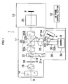
- Fig: 1 is a block diagram showing a main configuration of a television camera system to which an automatic focusing system according to an embodiment of the present invention is applied.
- the television camera system 1 shown in Fig. 1 comprises a camera main body 10, a photographing lens 11 and an AF frame operating section 12.
- the AF frame operating section 12 will be described later.
- the camera main body 10 includes a visual image pickup device or the like for photographing images to be broadcasted, and outputting or recording image signals of a predetermined format onto a storage medium.
- the photographing lens 11 is detachably mounted onto a mount section of the camera main body 10.
- An optical system of the photographing lens 11 comprises a focusing lens group 14, a zoom lens group 16, an iris (diaphragm) 18, a relay lens group 20, and an extender 21 or the like.
- the extender 21 is provided between the iris 18 and the relay lens group 20, and comprises a plurality of lens units 21a capable of advancing and retreating in regards to an optical axis O.
- Each lens unit 21a consists of, for instance, a plurality of lenses at magnifications of 2x, 1x, 0.8x and the like.
- the relay lens group 20 is composed of a front-side relay lens 20A and a rear-side relay lens 20B.
- a half mirror 22 for separating a subject light for focus state detection from a subject light incident via the photographic lens 11 is placed on the optical axis O between the front-side relay lens 20A and the rear-side relay lens 20B.
- the half mirror 22 is positioned so that its mirror surface 22a is roughly at 45 degrees to the optical axis O of the photographing lens 11, and reflects subject light passing through the front-side relay lens 20A at roughly a right angle, thereby dispersing as an optical axis O' from the visual image subject light.
- the subject light transmitted through the half mirror 22 is projected as the visual image subject light from the rear end-side of the photographing lens 11, and enters an image capturing section 24 of the camera main body 10. While a detailed description of the image capturing section 24 will be omitted, subject light incident to the image capturing section 24 is separated into, for instance, light of the three colors of red, green and blue by a color separation optical system, and are then incident to image capturing surfaces of the visual image pickup device respectively provided for each color. Color visual images for broadcasting or the like are thereby photographed.
- the reference character P in the drawing designates a focus surface P, which is a position on the optical axis O that is optically equivalent to the photographing surface of the visual image pickup device.
- the subject light reflected by the half mirror 22 proceeds as a focus state detection subject light along an optical axis O' roughly perpendicular to the optical axis O, and is incident to a focus state detecting section 30 via a formed image position changing lens 26.
- the focus state detecting section 30 comprises a beam splitter 32 which bisects the focus state detection subject light, two focus state detection image pickup devices A and B to which the focus state detection subject light bisected by the beam splitter 32 enters, and drive apparatuses 34 which drive the focus state detection image pickup devices A and B.
- the beam splitter 32 is composed of two prisms 32a and 32b. As described above, the focus state detection subject light separated from the subject light by the half mirror 22 proceeds along the optical axis O', and first enters the prism 32a. At the prism 32a, the focus state detection subject light is divided into a reflected light and a transmitted light by a half mirror 32c, and the reflected light proceeds along an optical axis O" to enter the focus state detection image pickup device A, while the transmitted light is incident to the prism 32b before entering the focus state detection image pickup device B.
- CCDs Charge Coupled Devices
- the drive apparatuses 34 respectively drive the focus state detection image pickup devices A and B along the optical axes O" and O'.
- the drive apparatuses 34 respectively provided for the focus state detection image pickup devices A and B have similar structures. Therefore, the drive apparatus 34 for the focus state detection image pickup device A will now be described in detail.
- Figs. 2A and 2B are diagrams showing a drive apparatus for an automatic focusing system according to an embodiment of the present invention.
- Fig. 2A is a side view
- Fig. 2B is a plan view.
- the drive apparatus 34 comprises a holding frame 40 provided on a photographing lens 11 side, a frame 42 for supporting the focus state detection image pickup device A (B), a spring 44, a motor 46, a potentiometer 48, and a rotating shaft 50 with a male screw provided on its circumferential surface.
- Guide grooves 40a and 40b are formed on the holding frame 40. These guide grooves 40a and 40b support the frame 42 to move slidably in a direction parallel to the optical axis O' (O"). By sliding the frame 42 along the guide grooves 40a and 40b, the focus state detection image pickup device A supported by the frame 42 can be moved back and forth along the optical axis O' (O") (arrow in Fig. 2A).
- a screw 44 that applies biasing force to the frame 42 is provided on an edge of the guiding groove 40b of the holding frame 40. Due to the screw 44, the frame 42 is constantly biased in a direction corresponding to the right side in Fig. 2A.
- a support hole 52 which supports the rotating shaft 50 to be rotationally movable is formed on an edge of the guide groove 40b that faces the screw 44 of the holding frame 40.
- a female screw which screws on to the male screw of the rotating shaft 50 is formed on the inner circumferential surface of the support hole 52.
- a front end section (left in Fig. 2A) of the rotating shaft 50 is in contact with the frame 42, and biases the frame 42 against the biasing force of the screw 44 towards the left in Fig. 2A by the feeding effect of the screw caused by the rotational movement of the rotating shaft 50 and the translatory effect of the rotating shaft 50.
- a gear 54 is mounted to a rear end section of the rotating shaft 50.
- the gear 58 meshes with a gear 62 mounted on an output shaft 60 of the motor 46.
- the focus state detection image pickup device A (B) can be driven back and forth along the optical axis O' (O"), supported by the frame 42, by driving the motor 46.
- rotation of the gear 58 is detected by the potentiometer 48. The rotation detection by the potentiometer 48 enables detection of the position of the focus state detection image pickup device A (B), to be described in detail later.
- Fig. 3 is a block diagram showing a main configuration of a photographing lens 11. Images photographed by the focus state detection image pickup devices A and B are inputted to a signal processing section 70.
- the signal processing section 70 detects focus states of the photographing lens 11 based on the inputted image signals, and comprises a central processing unit (CPU) 72 which functions as a control device, as well as an A/D converter 74, a D/A converter 76, a focusing demand 78, a zoom demand 80 and the like.
- CPU central processing unit
- the CPU 72 functions both as a control device which controls according to a predetermined program devices such as the focusing lens group 14 or the zoom lens group 16 within the photographing lens 11, and as a control device for controlling the focus state detection image pickup devices A and B.
- the CPU 72 comprises a ROM storing a control program and various data tables necessary for control or calculations, a RAM to be used as a working storage area, and the like.
- Focus of the photographing lens 11 is controlled by manual focusing (MF) or automatic focusing (AF).
- a focusing demand 78 outputs focusing demand data which instructs a moving position of the focusing lens group 14 via the A/D converter 74 to the CPU 72 in response to an amount of rotational operation of a focus knob, not shown, provided on a periphery of the photographing lens 11.
- the CPU 72 Based on the focusing demand data, the CPU 72 outputs a control signal to a drive circuit 84 of a focusing motor 82, and drives the focusing lens group 14 of the photographing lens 11.
- movement speed of the focusing lens group 14 and the like is calculated based on the loaded focusing demand data and positional data of the focusing lens group 14 inputted via the A/D converter 74 from a focusing potentiometer 86.
- a zoom demand 80 outputs zoom demand data which instructs moving speed of the zoom lens group 16 via the A/D converter 74 to the CPU 72 in response to a direction and an amount of rotation of a zoom ring which is provided to be rotationally movable on a periphery of the photographing lens 11.
- the CPU 72 Based on the zoom demand data, the CPU 72 outputs a control signal to a drive circuit 90 of a zoom motor 88, and drives the zoom lens group 16 of the photographing lens 11.
- movement of the zoom lens group 16 and the like is calculated based on the loaded zoom demand data and positional data of the zoom lens group 16 inputted via the A/D converter 74 from a potentiometer 92.
- the CPU 72 also calculates a drive amount of an iris motor 96 based on an diaphragm value data inputted from a potentiometer 94 for the iris 18 via the A/D converter 74, and an iris control signal provided by the camera main body 10, and outputs a control signal for the iris motor 96 to a drive circuit 98 of the iris motor 96 via the D/A converter 76.
- the CPU 72 further outputs a lens unit change signal for the extender 21 to a drive circuit 102 of the extender 21 via the D/A converter 76, depending on operation of an extender select lever, not shown, provided on the exterior of the photographing lens 11.
- the drive circuit 102 drives a drive motor 104 of the extender 21, and advances a selected lens unit onto the optical axis O (refer to Fig. 1).
- the reference numeral 106 designates a sensor for detecting the type of the lens unit advanced onto the optical axis O.
- AF images photographed by the focus state detection image pickup devices A and B are outputted to the CPU 72 of the signal processing section 70.
- the CPU 72 detects the focus state of the photographing lens 11 based on visual image signals obtained from the focus state detection image pickup devices A and B.
- the CPU 72 next outputs a control signal to the drive circuit 84 of the focusing motor 82 based on the detected focus state via the D/A converter 76, and performs AF control of the photographing lens 11. This AF control will be described later.
- a motor 46 of the drive apparatus 34 of the focus state detection image pickup device A is activated based on a drive signal from a drive circuit 110.
- the drive circuit 110 drives the motor 46 based on a control signal outputted from the D/A converter 76 of the signal processing section 70.
- the movement of the focus state detection image pickup device A is controlled.
- the potentiometer 48 detects the position of the focus state detection image pickup device A based on the number of rotations of the input shaft 56 (refer to Fig. 2A), and outputs the positional data thereof to the A/D converter 74 of the signal processing section 70.
- the drive apparatus 34 of the focus state detection image pickup device B is similar in configuration to that of the focus state detection image pickup device A, and the motor 46 is driven based on a control signal outputted from the D/A converter 76 to control movement of the focus state detection image pickup device B.
- the position of the focus state detection image pickup device B is detected by the potentiometer 48, and positional data thereof is outputted to the A/D converter 74 of the signal processing section 70.
- Images of a subject captured by the focus state detection image pickup devices A and B are respectively outputted to the signal processing section 70 as video signals with a predetermined format, and are inputted to the CPU 72 after being converted to focus evaluation value (VA, VB) signals that indicate sharpness or contrast of the images by bypass filters 120a and 120b, A/D converters 122a and 122b, gate circuits 124a and 124b, and adding machines 126a and 126b of the signal processing section 70.
- VA, VB focus evaluation value
- the video signals outputted from the focus state detection image pickup devices A and B are respectively inputted to the bypass filters 120a and 120b, and their high frequency components are extracted.
- the signals of the high frequency components extracted by the bypass filters 120a and 120b are respectively converted into digital signals by the A/D converters 122a and 122b.
- the gate circuits 124a and 124b are respectively extracted among the one screen's worth (one field's worth) of the digital signals of the images photographed by the focus state detection image pickup devices A and B.
- the values of digital signals of the extracted range are added by the adding machines 126a and 126b.
- a total sum of the values of the high frequency components of the video signals within the predetermined focus area is thereby obtained, and the obtained values become the focus evaluation values VA and VB, which indicate a level of sharpness of the image within the predetermined focus area.
- Various synchronization signals are applied from a synchronization signal generating circuit, not shown, to the focus state detection image pickup devices A and B and the respective circuits such as the gate circuits 124a and 124b to achieve synchronization of processing performed at each circuit.
- a vertical synchronization signal (V signal) for each field of the video signal is applied from the synchronization signal generating circuit to the CPU 72.
- the CPU 72 Based on the focus evaluation values VA and VB obtained in this manner, the CPU 72 detects a current focus state of the photographing lens 11 in relation to the photographing surface (the focus surface P shown in Fig. 1) of the visual image pickup device.
- Fig. 4 is a graph illustrating focus evaluation values.
- a horizontal axis represents focus positions of the photographing lens 12, while a vertical axis represents focus evaluation values.
- Curved lines SA and SB indicated by continuous lines represent focus evaluation values respectively obtained from the automatic focusing image pickup devices A and B, while a curved line SC indicated by a dotted line is a focus evaluation value obtained from an visual image pickup device (P).
- a position F1 where the focus evaluation value reaches maximum (maximal) is the correct focus position of the visual image pickup device C.
- the focus evaluation values obtained from each focus state detection image pickup devices A and B are values VA1 and VB1 corresponding to the position F1 on the respective curved lines SA and SB.
- the focus evaluation values obtained from each focus state detection image pickup devices A and B are values VA2 and VB2 corresponding to the position F2 on the respective curved lines SA and SB.
- the focus evaluation value VA2 obtained from the focus state detection image pickup device A is greater than the focus evaluation value VB2 obtained from the focus state detection image pickup device B (VA2>VB2).
- the focus position of the photographing lens 11 is set to the near side of the correct focus position F1, i.e., at a front-focus position.
- the focus evaluation values obtained from each focus state detection image pickup devices A and B are values VA3 and VB3 corresponding to the position F3 on the respective curved lines SA and SB.
- the focus evaluation value VA3 obtained from the focus state detection image pickup device A is smaller than the focus evaluation value VB3 obtained from the focus state detection image pickup device B (VA3 ⁇ VB3).
- the focus position of the photographing lens 11 is set to the infinity side of the correct focus position F1, i.e., at a rear focus position.
- the zoom lens group 16 of the photographing lens 11 is operated to shift the focal length to a wide angle side (i.e., shortened), the amount of displacement of the focus position corresponding to the optical path length increases, and the curved lines SA and SB become more spaced in relation to the focus position.
- the positions of the focus state detection image pickup devices A and B can be moved so that the optical path length difference decreases, making the curved lines SA and SB approach each other, and thereby enabling detection of a focus state.
- the automatic focusing apparatus enables optimum configuration of optical path lengths by moving focus state detection image pickup devices back and forth along the direction of an optical axis of a focus state detection subject light, thereby constantly enabling detection of appropriate focus states.
- Fig. 5 is a plan view showing the AF operating section 12.
- the AF operating section 12 comprises a joystick 130, an AF start switch 132 and a tracking starting switch 134.
- the joystick 130 is a member that is operated to designate AF area positions within the photographing screen.
- the AF start switch 132 is a member that is operated to perform automatic focusing so that a subject within the AF area designated by the joystick 130 achieves best focus.
- the tracking starting switch 134 is a switch for initiating an automatic tracking mode that automatically tracks the AF area in accordance with the movement of the subject in best focus in the photographing screen.
- Fig. 6 is a diagram showing a photographing screen. As shown in Fig. 6, the photographing screen 140 is divided into a plurality of regions 140A. Reference numeral 142 designates an AF frame, which indicates an AF area within the photographing screen.
- the automatic focusing apparatus respectively detects a focus state for each region 140A.
- a "0" sign is displayed for a region 140A that includes a subject in best focus
- a "+ " sign is displayed for a region 140A that includes a subject in front focus
- a region 140A that includes a subject in rear focus is displayed by a "-" sign.
- a region 140A displayed by none of the signs "0", "+” or "-” is either a region with a blurred subject or a region without a subject.
- an input is first provided by operating the joystick 130 to move the AF frame 142 to the position of a main subject 144 (person).
- the AF start switch 132 When the AF start switch 132 is pressed, automatic focusing is performed so that the main subject 144 in the AF frame 142 comes into best focus.
- a group of regions including the subject 144 (person) near the AF frame 142 is now in best focus, and a group of regions including a subject 146 (tree), shown to the right of the subject 144 in Fig.
- a subject 148 (a subject with high contrast, such as an multi-colored object with a significant difference in luminance), shown to the left of the subject 144 in Fig. 6, is now in front focus.
- Each focus state of the regions 140A is detected by the CPU 72 and stored in a RAM.
- the tracking starting switch 134 is pressed and the mode is set to automatic tracking mode
- the focus state of each region 140A stored in the RAM by the CPU 72 is referenced, and a movement of a group of regions in best focus (in Fig. 6, the group of regions displayed by "0" signs in the AF frame 142 and its vicinity) is detected.
- the AF frame 142 moves in accordance with the movement of a group of regions in best focus, while automatic focusing is simultaneously performed so that the subject 144 in the AF frame 142 comes into best focus.
- the automatic tracking mode is deactivated, thereby stopping the movement of the AF frame 142 that has been moving in accordance with the movement of the main subject 144.
- the position of the AF frame 142 can be manually designated using the joystick 130.
- automatic tracking can be arranged to terminate to preferentially accept manual operation by the joystick 130.
- Fig. 7 is a graph illustrating a focus state of a subject within the photographing screen of Fig. 6.
- a horizontal axis of Fig. 7 represents focus positions of the focusing lens group 14, while a vertical axis represents focus evaluation values.
- the focus evaluation values of the three subjects 144 to 148 respectively detected for each region 140A are shown on the same graph.
- the focus evaluation value of the main subject 144 is lower than those of the subjects 146 and 148, by respectively detecting a focus state (best focus, front focus, rear focus, blurring or the like) for each region 140A, the AF frame 142 can be tracked so that the main subject 144 comes into best focus.
- Fig. 8 is a flowchart showing a flow of processing by a CPU 72 during automatic tracking mode.
- an input is provided by operating the joystick 130 to configure the AF frame 142 to overlap with the main subject 144 (step S10).
- the step S10 can be arranged so that the size and shape of the AF frame 142 is adjustable according to the size and shape of the main subject 144.
- the AF start switch 132 is pressed, automatic focusing is performed so that the main subject 144 in the AF frame 142 comes into best focus (step S12).
- step S 14 if not set to automatic tracking mode (No in step S 14), the process returns to step S 10 to continue manual configuration of the AF frame.
- the tracking starting switch has been pushed and the automatic tracking mode is set (Yes in step S 14)
- a focus state is respectively detected for each region 140A in the photographing screen 140 and stored in the RAM (step S16). Then, the focus state of each region 140A stored in the RAM are referenced, and a movement of a group of regions in best focus (in Fig. 6, the group of regions displayed by "0" signs) is detected.
- the AF frame 142 moves in accordance with the movement of a group of regions in best focus (step S 18), while automatic focusing is simultaneously performed so that the subject 144 in the AF frame 142 comes into best focus (step S20).
- the AF frame 142 can be arranged, for instance, to move so as to entirely include the group of regions in best focus, or to move so that the center (or the center of gravity) of the AF frame 142 is congruent with the center of gravity of the group of regions in best focus.
- the size of the AF frame 142 can be arranged to change accordingly.
- step S22 if photographing under the automatic tracking mode is ongoing (No in step S22), the process returns to step S 16. On the other hand, if the tracking starting switch 134 is pressed and either the automatic tracking mode is deactivated or photographing is concluded (Yes in step S22), the above processing is terminated.
- the main subject 144 by respectively detecting a focus state (best focus, front focus, rear focus, blurring or the like) for each region 140A in the photographing screen 140, the main subject 144 can be accurately detected and the AF frame 142 can be tracked even when a subject with a higher contrast than the subject 144 exists.
- the AF frame 142 is preferably moved in accordance with a group of regions with the biggest or smallest size, or with a group of regions with a high contrast.
- the step S18 may be arranged so that an indication prompting manual configuration of the AF frame 142 using the joystick 130 is displayed.
- the present embodiment may be arranged so that the size of the AF frame 142 is adjusted in accordance with such zooming.
- the present embodiment has been configured so that, a focus state is respectively detected for each region 140A in the photographing screen 140 by providing a plurality of focus state detection image pickup devices A and B with different optical path lengths
- the present invention is not limited to this configuration.
- wobbling of the focusing lens group 14 may be performed to detect focus evaluation values, thereby detecting a focus state for each region 140A.
- the configuration of the automatic focusing apparatus according to the present embodiment is not limited to the above. While the present embodiment is configured so that the focus state detection image pickup devices A and B are driven by motors 46, a configuration in which the focus state detection image pickup devices A and B are driven by an actuator using piezoelectric elements or the like is also possible.
- the present embodiment has been described with respect to an example where the automatic focusing apparatus of the present invention is applied to the photographing lens of a television camera system for purposes of broadcasting or the like, the scope of application of the present invention is not limited to these purposes.
- the present invention can also be applied to the photographing lenses of conventional cameras such as digital cameras.
Landscapes
- Physics & Mathematics (AREA)
- Engineering & Computer Science (AREA)
- Multimedia (AREA)
- Signal Processing (AREA)
- General Physics & Mathematics (AREA)
- Optics & Photonics (AREA)
- Automatic Focus Adjustment (AREA)
- Studio Devices (AREA)
- Focusing (AREA)
Abstract
Description
- The present invention relates to an automatic focusing apparatus, and more particularly, to a technique used for detecting correct focus in automatic focusing control of photographic lens.
- Conventionally, in camera systems where an AF area for performing automatic focusing is configured within a photographing screen, either framing is performed so that a subject to be brought into focus enters the AF area, or a position of the AF area within the photographing screen is moved in accordance with the movement of the subject. However, in order to shoot a subject that is either fast-moving or has a drastically changing shape, taking shots while keeping the subject inside the AF area may prove difficult. In order to solve this problem, for example, technologies for tracking a subject within a photographing screen are disclosed in
Japanese Patent No. 2663451 Japanese Patent No. 2675807 - The technologies disclosed in the above-mentioned
Japanese Patent No. 2663451 Japanese Patent No. 2675807 - The present invention was made in consideration of these circumstances, and its object is to provide an automatic focusing apparatus capable of maintaining correct focus on a main subject even when the main subject moves within a photographing screen.
- In order to achieve the above object, an automatic focusing apparatus according to a first aspect of the present invention comprises: a region configuring device which configures a main subject region including a main subject within a photographing screen; a focusing control device which controls focusing so that a focus state of the main subject included in the configured main subject region is a best focus state; a focus state obtaining device which divides the photographing screen into a plurality of regions and obtains a focus state from each region; a focus state storage device which stores the focus state obtained from each region; a movement detecting device which references the stored focus state of each region to detect movement of a group of regions that are located either within the main subject region and its vicinity or within the main subject region and are in a best focus state; and a region moving device which moves the main subject region in accordance with the movement of the group of regions that are located either within the main subject region and its vicinity or within the main subject region and are in the best focus state.
- In the automatic focusing apparatus according to the first aspect, storing a focus state (best focus, front focus, rear focus, blurring or the like) of each region enables accurate detection of a main subject and movement of a main subject region even when a subject with a higher contrast than the main subject exists.
- In an automatic focusing apparatus according to a second aspect of the present invention, the focus state according to the first aspect comprises the respective states of best focus, front focus, rear focus or blurring. The second aspect limits the focus states of the first aspect.
- An automatic focusing apparatus according to a third aspect of the present invention is the automatic focusing apparatus according to the first aspect or the second aspect, further comprising: a subject light separating device which separates a subject light for focus state detection from a main optical path which guides a subject light incident to a photographic lens to a visual image pickup device for obtaining an image signal for either recording or playback; an image pickup device which captures the separated subject light for focus state detection using a plurality of image capturing surfaces placed at positions with optical path lengths that differ from one another; and a focus evaluation value calculation device which calculates, for each region, focus evaluation values of the subject image based on image signals captured and obtained by the plurality of image capturing surfaces of the image pickup device; wherein the focus state obtaining device obtains the focus state of each region based on the focus evaluation values.
- In the automatic focusing apparatus according to the third aspect, since the focus state of each region can be detected from the image signals of one field (or one frame), a main subject region can be moved at high speed and with high precision.
- An automatic focusing apparatus according to a fourth aspect of the present invention is the automatic focusing apparatus according to the first to third aspects, further comprising a movement stopping device which stops the movement of the main subject region by the region moving device, wherein the region configuring device accepts configuration of the main subject region when the movement of the main subject region is stopped.
- In the automatic focusing apparatus according to the fourth aspect, a main subject region can be manually configured, for example, when changing main subjects is desired during shooting.
- An automatic focusing apparatus according to a fifth aspect of the present invention is the automatic focusing apparatus according to the first to third aspects, wherein operation of the region configuration device is preferentially accepted when the region configuration device is executed during the movement of the main subject region by the region moving device.
- In the automatic focusing apparatus according to the fifth aspect, an interruption operation for configuring a main subject region can be performed manually while automatic tracking of the main subject region by the region moving device is in progress.
- According to the present invention, even when a subject with a contrast that is higher than a main subject exists, the main subject can be accurately detected by storing the focus state (best focus, front focus, rear focus, blurring or the like) of each divided region of the photographing screen and moving the main subject region to a best focus position.
-
- Fig. 1 is a block diagram showing a main configuration of a television camera system to which an automatic focusing system according to an embodiment of the present invention is applied;
- Figs. 2A and 2B are diagrams showing a drive apparatus for an automatic focusing system according to an embodiment of the present invention;
- Fig. 3 is a block diagram showing a main configuration of a photographing
lens 11; - Fig. 4 is a graph illustrating focus evaluation values;
- Fig. 5 is a plan view showing an
AF operating section 12; - Fig. 6 is a diagram showing a photographing screen;
- Fig. 7 is a graph illustrating a focus state of a subject within the photographing screen of Fig. 6; and
- Fig. 8 is a flowchart showing a flow of processing by a
CPU 72 during automatic tracking mode. - A preferred embodiment of an automatic focusing apparatus according to the present invention will now be described with reference to the accompanying drawings.
- Fig: 1 is a block diagram showing a main configuration of a television camera system to which an automatic focusing system according to an embodiment of the present invention is applied. The television camera system 1 shown in Fig. 1 comprises a camera
main body 10, a photographinglens 11 and an AFframe operating section 12. The AFframe operating section 12 will be described later. - The camera
main body 10 includes a visual image pickup device or the like for photographing images to be broadcasted, and outputting or recording image signals of a predetermined format onto a storage medium. The photographinglens 11 is detachably mounted onto a mount section of the cameramain body 10. - An optical system of the photographing
lens 11 comprises a focusinglens group 14, azoom lens group 16, an iris (diaphragm) 18, arelay lens group 20, and anextender 21 or the like. - The
extender 21 is provided between theiris 18 and therelay lens group 20, and comprises a plurality oflens units 21a capable of advancing and retreating in regards to an optical axis O. Eachlens unit 21a consists of, for instance, a plurality of lenses at magnifications of 2x, 1x, 0.8x and the like. - The
relay lens group 20 is composed of a front-side relay lens 20A and a rear-side relay lens 20B. Ahalf mirror 22 for separating a subject light for focus state detection from a subject light incident via thephotographic lens 11 is placed on the optical axis O between the front-side relay lens 20A and the rear-side relay lens 20B. Thehalf mirror 22 is positioned so that itsmirror surface 22a is roughly at 45 degrees to the optical axis O of the photographinglens 11, and reflects subject light passing through the front-side relay lens 20A at roughly a right angle, thereby dispersing as an optical axis O' from the visual image subject light. - The subject light transmitted through the
half mirror 22 is projected as the visual image subject light from the rear end-side of the photographinglens 11, and enters animage capturing section 24 of the cameramain body 10. While a detailed description of theimage capturing section 24 will be omitted, subject light incident to theimage capturing section 24 is separated into, for instance, light of the three colors of red, green and blue by a color separation optical system, and are then incident to image capturing surfaces of the visual image pickup device respectively provided for each color. Color visual images for broadcasting or the like are thereby photographed. The reference character P in the drawing designates a focus surface P, which is a position on the optical axis O that is optically equivalent to the photographing surface of the visual image pickup device. - The subject light reflected by the
half mirror 22 proceeds as a focus state detection subject light along an optical axis O' roughly perpendicular to the optical axis O, and is incident to a focusstate detecting section 30 via a formed imageposition changing lens 26. - The focus
state detecting section 30 comprises abeam splitter 32 which bisects the focus state detection subject light, two focus state detection image pickup devices A and B to which the focus state detection subject light bisected by thebeam splitter 32 enters, and driveapparatuses 34 which drive the focus state detection image pickup devices A and B. - The
beam splitter 32 is composed of twoprisms half mirror 22 proceeds along the optical axis O', and first enters theprism 32a. At theprism 32a, the focus state detection subject light is divided into a reflected light and a transmitted light by ahalf mirror 32c, and the reflected light proceeds along an optical axis O" to enter the focus state detection image pickup device A, while the transmitted light is incident to theprism 32b before entering the focus state detection image pickup device B. - For instance, CCDs (Charge Coupled Devices) for photographing black and white or color images are used as the focus state detection image pickup devices A and B.
- The
drive apparatuses 34 respectively drive the focus state detection image pickup devices A and B along the optical axes O" and O'. Thedrive apparatuses 34 respectively provided for the focus state detection image pickup devices A and B have similar structures. Therefore, thedrive apparatus 34 for the focus state detection image pickup device A will now be described in detail. - Figs. 2A and 2B are diagrams showing a drive apparatus for an automatic focusing system according to an embodiment of the present invention. Fig. 2A is a side view, while Fig. 2B is a plan view. As shown in Figs. 2A and 2B, the
drive apparatus 34 comprises aholding frame 40 provided on a photographinglens 11 side, aframe 42 for supporting the focus state detection image pickup device A (B), aspring 44, amotor 46, apotentiometer 48, and a rotatingshaft 50 with a male screw provided on its circumferential surface. - Guide grooves 40a and 40b, roughly parallel to the optical axis O' (O"), are formed on the
holding frame 40. These guidegrooves frame 42 to move slidably in a direction parallel to the optical axis O' (O"). By sliding theframe 42 along theguide grooves frame 42 can be moved back and forth along the optical axis O' (O") (arrow in Fig. 2A). - A
screw 44 that applies biasing force to theframe 42 is provided on an edge of the guidinggroove 40b of the holdingframe 40. Due to thescrew 44, theframe 42 is constantly biased in a direction corresponding to the right side in Fig. 2A. - On the other hand, a
support hole 52 which supports therotating shaft 50 to be rotationally movable is formed on an edge of theguide groove 40b that faces thescrew 44 of the holdingframe 40. A female screw which screws on to the male screw of therotating shaft 50 is formed on the inner circumferential surface of thesupport hole 52. A front end section (left in Fig. 2A) of therotating shaft 50 is in contact with theframe 42, and biases theframe 42 against the biasing force of thescrew 44 towards the left in Fig. 2A by the feeding effect of the screw caused by the rotational movement of therotating shaft 50 and the translatory effect of therotating shaft 50. - A
gear 54 is mounted to a rear end section of therotating shaft 50. A gear 58 mounted to a rotation detectinginput shaft 56 of thepotentiometer 48 meshes with thegear 54. In addition, the gear 58 meshes with agear 62 mounted on anoutput shaft 60 of themotor 46. - In the
drive apparatus 34 thus configured, the focus state detection image pickup device A (B) can be driven back and forth along the optical axis O' (O"), supported by theframe 42, by driving themotor 46. In addition, rotation of the gear 58 is detected by thepotentiometer 48. The rotation detection by thepotentiometer 48 enables detection of the position of the focus state detection image pickup device A (B), to be described in detail later. - Fig. 3 is a block diagram showing a main configuration of a photographing
lens 11. Images photographed by the focus state detection image pickup devices A and B are inputted to asignal processing section 70. Thesignal processing section 70 detects focus states of the photographinglens 11 based on the inputted image signals, and comprises a central processing unit (CPU) 72 which functions as a control device, as well as an A/D converter 74, a D/A converter 76, a focusingdemand 78, azoom demand 80 and the like. - The
CPU 72 functions both as a control device which controls according to a predetermined program devices such as the focusinglens group 14 or thezoom lens group 16 within the photographinglens 11, and as a control device for controlling the focus state detection image pickup devices A and B. TheCPU 72 comprises a ROM storing a control program and various data tables necessary for control or calculations, a RAM to be used as a working storage area, and the like. - Focus of the photographing
lens 11 is controlled by manual focusing (MF) or automatic focusing (AF). - During MF, a focusing
demand 78 outputs focusing demand data which instructs a moving position of the focusinglens group 14 via the A/D converter 74 to theCPU 72 in response to an amount of rotational operation of a focus knob, not shown, provided on a periphery of the photographinglens 11. Based on the focusing demand data, theCPU 72 outputs a control signal to adrive circuit 84 of a focusingmotor 82, and drives the focusinglens group 14 of the photographinglens 11. At theCPU 72, movement speed of the focusinglens group 14 and the like is calculated based on the loaded focusing demand data and positional data of the focusinglens group 14 inputted via the A/D converter 74 from a focusingpotentiometer 86. - On the other hand, a
zoom demand 80 outputs zoom demand data which instructs moving speed of thezoom lens group 16 via the A/D converter 74 to theCPU 72 in response to a direction and an amount of rotation of a zoom ring which is provided to be rotationally movable on a periphery of the photographinglens 11. Based on the zoom demand data, theCPU 72 outputs a control signal to adrive circuit 90 of azoom motor 88, and drives thezoom lens group 16 of the photographinglens 11. At theCPU 72, movement of thezoom lens group 16 and the like is calculated based on the loaded zoom demand data and positional data of thezoom lens group 16 inputted via the A/D converter 74 from apotentiometer 92. - The
CPU 72 also calculates a drive amount of aniris motor 96 based on an diaphragm value data inputted from apotentiometer 94 for theiris 18 via the A/D converter 74, and an iris control signal provided by the cameramain body 10, and outputs a control signal for theiris motor 96 to adrive circuit 98 of theiris motor 96 via the D/A converter 76. - The
CPU 72 further outputs a lens unit change signal for theextender 21 to adrive circuit 102 of theextender 21 via the D/A converter 76, depending on operation of an extender select lever, not shown, provided on the exterior of the photographinglens 11. Receiving this signal, thedrive circuit 102 drives adrive motor 104 of theextender 21, and advances a selected lens unit onto the optical axis O (refer to Fig. 1). Thereference numeral 106 designates a sensor for detecting the type of the lens unit advanced onto the optical axis O. - During AF, images photographed by the focus state detection image pickup devices A and B are outputted to the
CPU 72 of thesignal processing section 70. TheCPU 72 detects the focus state of the photographinglens 11 based on visual image signals obtained from the focus state detection image pickup devices A and B. TheCPU 72 next outputs a control signal to thedrive circuit 84 of the focusingmotor 82 based on the detected focus state via the D/A converter 76, and performs AF control of the photographinglens 11. This AF control will be described later. - A
motor 46 of thedrive apparatus 34 of the focus state detection image pickup device A is activated based on a drive signal from adrive circuit 110. Thedrive circuit 110 drives themotor 46 based on a control signal outputted from the D/A converter 76 of thesignal processing section 70. Thus, the movement of the focus state detection image pickup device A is controlled. - The
potentiometer 48 detects the position of the focus state detection image pickup device A based on the number of rotations of the input shaft 56 (refer to Fig. 2A), and outputs the positional data thereof to the A/D converter 74 of thesignal processing section 70. - The
drive apparatus 34 of the focus state detection image pickup device B is similar in configuration to that of the focus state detection image pickup device A, and themotor 46 is driven based on a control signal outputted from the D/A converter 76 to control movement of the focus state detection image pickup device B. In addition, the position of the focus state detection image pickup device B is detected by thepotentiometer 48, and positional data thereof is outputted to the A/D converter 74 of thesignal processing section 70. - Processing for focus state detection will now be described specifically. Images of a subject captured by the focus state detection image pickup devices A and B are respectively outputted to the
signal processing section 70 as video signals with a predetermined format, and are inputted to theCPU 72 after being converted to focus evaluation value (VA, VB) signals that indicate sharpness or contrast of the images bybypass filters D converters gate circuits machines signal processing section 70. For instance, when CCDs which photograph black and white images are used as the focus state detection image pickup devices A and B, video signals outputted from the focus state detection image pickup devices A and B to thesignal processing section 70 become luminance signals indicating luminance of each pixel composing each screen. - Processing for obtaining the focus evaluation values VA and VB will now be explained. The video signals outputted from the focus state detection image pickup devices A and B are respectively inputted to the bypass filters 120a and 120b, and their high frequency components are extracted. The signals of the high frequency components extracted by the bypass filters 120a and 120b are respectively converted into digital signals by the A/
D converters gate circuits machines - Various synchronization signals are applied from a synchronization signal generating circuit, not shown, to the focus state detection image pickup devices A and B and the respective circuits such as the
gate circuits CPU 72. - Based on the focus evaluation values VA and VB obtained in this manner, the
CPU 72 detects a current focus state of the photographinglens 11 in relation to the photographing surface (the focus surface P shown in Fig. 1) of the visual image pickup device. - Effects of the automatic focusing apparatus according to the present invention will now be described. First, a description will be provided on focus evaluation values. Fig. 4 is a graph illustrating focus evaluation values. In Fig. 4, a horizontal axis represents focus positions of the photographing
lens 12, while a vertical axis represents focus evaluation values. Curved lines SA and SB indicated by continuous lines represent focus evaluation values respectively obtained from the automatic focusing image pickup devices A and B, while a curved line SC indicated by a dotted line is a focus evaluation value obtained from an visual image pickup device (P). On the curved line SC, a position F1 where the focus evaluation value reaches maximum (maximal) is the correct focus position of the visual image pickup device C. - When the focus position of the photographing
lens 11 is set to the correct focus position F1, the focus evaluation values obtained from each focus state detection image pickup devices A and B are values VA1 and VB1 corresponding to the position F1 on the respective curved lines SA and SB. In this case, as for the relationships between each focus evaluation value, the focus evaluation value VA1 obtained from the focus state detection image pickup device A and the focus evaluation value VB 1 obtained from the focus state detection image pickup device B are equal to each other, while a focus evaluation value VC 1 of the focus state detection image pickup device C assumes a different value (VA1=VB1, VA1≠VC1, VB1≠VC1). Therefore, it can be understood that when the focus evaluation value VA1 obtained from the focus state detection image pickup device A and the focus evaluation value VB1 obtained from the focus state detection image pickup device B are equal to each other, while a focus evaluation value VC1 of a focus state detection image pickup device C assumes a different value, the focus position of the photographinglens 11 is set at the correct-focus position. F1. - On the other hand, when the focus position of the photographing
lens 11 is set to a position F2 on the near side of the correct focus position F1, the focus evaluation values obtained from each focus state detection image pickup devices A and B are values VA2 and VB2 corresponding to the position F2 on the respective curved lines SA and SB. In this case, as for the relationship between the focus evaluation value VA2 obtained from the focus state detection image pickup device A and the focus evaluation value VB2 obtained from the focus state detection image pickup device B, the focus evaluation value VA2 obtained from the focus state detection image pickup device A is greater than the focus evaluation value VB2 obtained from the focus state detection image pickup device B (VA2>VB2). Therefore, it can be understood that when the focus evaluation value VA2 obtained from the focus state detection image pickup device A is greater than the focus evaluation value VB2 obtained from the focus state detection image pickup device B, the focus position of the photographinglens 11 is set to the near side of the correct focus position F1, i.e., at a front-focus position. - Similarly, when the focus position of the photographing
lens 11 is set to a position F3 on the infinity side of the correct focus position F1, the focus evaluation values obtained from each focus state detection image pickup devices A and B are values VA3 and VB3 corresponding to the position F3 on the respective curved lines SA and SB. In this case, as for the relationship between the focus evaluation value VA3 obtained from the focus state detection image pickup device A and the focus evaluation value VB3 obtained from the focus state detection image pickup device B, the focus evaluation value VA3 obtained from the focus state detection image pickup device A is smaller than the focus evaluation value VB3 obtained from the focus state detection image pickup device B (VA3<VB3). Therefore, it can be understood that when the focus evaluation value VA3 obtained from the focus state detection image pickup device A is smaller than the focus evaluation value VB3 obtained from the focus state detection image pickup device B, the focus position of the photographinglens 11 is set to the infinity side of the correct focus position F1, i.e., at a rear focus position. - As the
zoom lens group 16 of the photographinglens 11 is operated to shift the focal length to a wide angle side (i.e., shortened), the amount of displacement of the focus position corresponding to the optical path length increases, and the curved lines SA and SB become more spaced in relation to the focus position. When a difference in focus evaluation values is not detected, the positions of the focus state detection image pickup devices A and B can be moved so that the optical path length difference decreases, making the curved lines SA and SB approach each other, and thereby enabling detection of a focus state. - As seen, the automatic focusing apparatus according to the present embodiment enables optimum configuration of optical path lengths by moving focus state detection image pickup devices back and forth along the direction of an optical axis of a focus state detection subject light, thereby constantly enabling detection of appropriate focus states.
- The AF
frame operating section 12 will now be described. Fig. 5 is a plan view showing theAF operating section 12. As shown in Fig. 5, theAF operating section 12 comprises ajoystick 130, anAF start switch 132 and atracking starting switch 134. Thejoystick 130 is a member that is operated to designate AF area positions within the photographing screen. The AF startswitch 132 is a member that is operated to perform automatic focusing so that a subject within the AF area designated by thejoystick 130 achieves best focus. Thetracking starting switch 134 is a switch for initiating an automatic tracking mode that automatically tracks the AF area in accordance with the movement of the subject in best focus in the photographing screen. - Fig. 6 is a diagram showing a photographing screen. As shown in Fig. 6, the photographing
screen 140 is divided into a plurality ofregions 140A.Reference numeral 142 designates an AF frame, which indicates an AF area within the photographing screen. The automatic focusing apparatus according to the present embodiment respectively detects a focus state for eachregion 140A. In Fig. 6, a "0" sign is displayed for aregion 140A that includes a subject in best focus, a "+ " sign is displayed for aregion 140A that includes a subject in front focus, and aregion 140A that includes a subject in rear focus is displayed by a "-" sign. Aregion 140A displayed by none of the signs "0", "+" or "-" is either a region with a blurred subject or a region without a subject. - In the present embodiment, as shown in Fig. 6, an input is first provided by operating the
joystick 130 to move theAF frame 142 to the position of a main subject 144 (person). When theAF start switch 132 is pressed, automatic focusing is performed so that themain subject 144 in theAF frame 142 comes into best focus. At this point, as shown in Figs. 6 and 7, a group of regions including the subject 144 (person) near theAF frame 142 is now in best focus, and a group of regions including a subject 146 (tree), shown to the right of the subject 144 in Fig. 6, is now in rear focus, while a subject 148 (a subject with high contrast, such as an multi-colored object with a significant difference in luminance), shown to the left of the subject 144 in Fig. 6, is now in front focus. Each focus state of theregions 140A is detected by theCPU 72 and stored in a RAM. - Next, when the
tracking starting switch 134 is pressed and the mode is set to automatic tracking mode, the focus state of eachregion 140A stored in the RAM by theCPU 72 is referenced, and a movement of a group of regions in best focus (in Fig. 6, the group of regions displayed by "0" signs in theAF frame 142 and its vicinity) is detected. Then, theAF frame 142 moves in accordance with the movement of a group of regions in best focus, while automatic focusing is simultaneously performed so that the subject 144 in theAF frame 142 comes into best focus. - In the present embodiment, for instance, when the
tracking starting switch 134 is pressed during automatic tracking mode, the automatic tracking mode is deactivated, thereby stopping the movement of theAF frame 142 that has been moving in accordance with the movement of themain subject 144. In this case, the position of theAF frame 142 can be manually designated using thejoystick 130. - In addition, when the
joystick 130 is operated during automatic tracking mode, automatic tracking can be arranged to terminate to preferentially accept manual operation by thejoystick 130. - Fig. 7 is a graph illustrating a focus state of a subject within the photographing screen of Fig. 6. A horizontal axis of Fig. 7 represents focus positions of the focusing
lens group 14, while a vertical axis represents focus evaluation values. In Fig. 7, the focus evaluation values of the threesubjects 144 to 148 respectively detected for eachregion 140A are shown on the same graph. As shown in Fig. 7, although the focus evaluation value of themain subject 144 is lower than those of thesubjects region 140A, theAF frame 142 can be tracked so that themain subject 144 comes into best focus. - Next, a flow of processing during automatic tracking mode will be described with reference to Fig. 8. Fig. 8 is a flowchart showing a flow of processing by a
CPU 72 during automatic tracking mode. First, an input is provided by operating thejoystick 130 to configure theAF frame 142 to overlap with the main subject 144 (step S10). The step S10 can be arranged so that the size and shape of theAF frame 142 is adjustable according to the size and shape of themain subject 144. Then, when theAF start switch 132 is pressed, automatic focusing is performed so that themain subject 144 in theAF frame 142 comes into best focus (step S12). - Next, if not set to automatic tracking mode (No in step S 14), the process returns to step
S 10 to continue manual configuration of the AF frame. On the other hand, if the tracking starting switch has been pushed and the automatic tracking mode is set (Yes in step S 14), a focus state is respectively detected for eachregion 140A in the photographingscreen 140 and stored in the RAM (step S16). Then, the focus state of eachregion 140A stored in the RAM are referenced, and a movement of a group of regions in best focus (in Fig. 6, the group of regions displayed by "0" signs) is detected. Then, theAF frame 142 moves in accordance with the movement of a group of regions in best focus (step S 18), while automatic focusing is simultaneously performed so that the subject 144 in theAF frame 142 comes into best focus (step S20). In step S18, theAF frame 142 can be arranged, for instance, to move so as to entirely include the group of regions in best focus, or to move so that the center (or the center of gravity) of theAF frame 142 is congruent with the center of gravity of the group of regions in best focus. In addition, when the size of the group of regions in best focus changes, the size of theAF frame 142 can be arranged to change accordingly. - Then, if photographing under the automatic tracking mode is ongoing (No in step S22), the process returns to step
S 16. On the other hand, if thetracking starting switch 134 is pressed and either the automatic tracking mode is deactivated or photographing is concluded (Yes in step S22), the above processing is terminated. - According to the present embodiment, by respectively detecting a focus state (best focus, front focus, rear focus, blurring or the like) for each
region 140A in the photographingscreen 140, themain subject 144 can be accurately detected and theAF frame 142 can be tracked even when a subject with a higher contrast than the subject 144 exists. In the above-described step S18, when the group of regions in best focus in the photographingscreen 140 separates into a plurality of groups, for instance, it is conceivable that a plurality of subjects (persons) in theAF frame 142 has started to move independently from each other. In such cases, theAF frame 142 is preferably moved in accordance with a group of regions with the biggest or smallest size, or with a group of regions with a high contrast. In addition, the step S18 may be arranged so that an indication prompting manual configuration of theAF frame 142 using thejoystick 130 is displayed. - In addition, when zooming is performed during the automatic tracking mode, the present embodiment may be arranged so that the size of the
AF frame 142 is adjusted in accordance with such zooming. - Furthermore, while the present embodiment has been configured so that, a focus state is respectively detected for each
region 140A in the photographingscreen 140 by providing a plurality of focus state detection image pickup devices A and B with different optical path lengths, the present invention is not limited to this configuration. For instance, wobbling of the focusinglens group 14 may be performed to detect focus evaluation values, thereby detecting a focus state for eachregion 140A. - Additionally, the configuration of the automatic focusing apparatus according to the present embodiment is not limited to the above. While the present embodiment is configured so that the focus state detection image pickup devices A and B are driven by
motors 46, a configuration in which the focus state detection image pickup devices A and B are driven by an actuator using piezoelectric elements or the like is also possible. - Moreover, while the present embodiment has been described with respect to an example where the automatic focusing apparatus of the present invention is applied to the photographing lens of a television camera system for purposes of broadcasting or the like, the scope of application of the present invention is not limited to these purposes. For instance, the present invention can also be applied to the photographing lenses of conventional cameras such as digital cameras.
Claims (5)
- An automatic focusing system comprising:a region configuring device which configures a main subject region including a main subject (144) within a photographing screen (140);a focusing control device (72) which controls focusing so that a focus state of the main subject (144) included in the configured main subject region is a best focus state;a focus state obtaining device (30) which divides the photographing screen (140) into a plurality of regions and obtains a focus state from each region;a focus state storage device which stores the focus state obtained from each region;a movement detecting device which references the stored focus state of each region to detect the movement of a group of regions that are located either within the main subject region and its vicinity or within the main subject region and are in a best focus state; anda region moving device (12) which moves the main subject region in accordance with the movement of the group of regions that are located either within the main subject region and its vicinity or within the main subject region and are in the best focus state.
- The automatic focusing apparatus according to claim 1, wherein
the focus state includes the respective states of best focus, front focus, back focus or blurring. - The automatic focusing apparatus according to claim 1 or 2, further comprising:a subject light separating device (32) which separates a subject light for focus state detection from a main optical path which guides a subject light incident to a photographic lens to a visual image pickup device for obtaining an image signal for either recording or playback;an image pickup device (A) (B) which captures the separated subject light for focus state detection using a plurality of image capturing surfaces placed at positions with optical path lengths that differ from one another;and a focus evaluation value calculation device (72) which calculates, for each region, a focus evaluation value of the subject image based on image signals captured and obtained by the plurality of image capturing surfaces of the image pickup device (A) (B),wherein the focus state obtaining device (30) obtains a focus state of each region based on the focus evaluation values.
- The automatic focusing apparatus according to any one of claims 1 to 3, further comprising:a movement stopping device (130) (134) which stops the movement of the main subject region by the region moving device (12), whereinthe region configuring device accepts configuration of the main subject region when the movement of the main subject region is stopped.
- The automatic focusing apparatus according to any one of claims 1 to 3, wherein
operation of the region configuration device is preferentially accepted when the region configuration device is executed during the movement of the main subject region by the region moving device (12).
Applications Claiming Priority (1)
| Application Number | Priority Date | Filing Date | Title |
|---|---|---|---|
| JP2005211689A JP2007025595A (en) | 2005-07-21 | 2005-07-21 | Automatic focusing device |
Publications (2)
| Publication Number | Publication Date |
|---|---|
| EP1746459A1 true EP1746459A1 (en) | 2007-01-24 |
| EP1746459B1 EP1746459B1 (en) | 2007-11-28 |
Family
ID=37139856
Family Applications (1)
| Application Number | Title | Priority Date | Filing Date |
|---|---|---|---|
| EP06015173A Not-in-force EP1746459B1 (en) | 2005-07-21 | 2006-07-20 | Automatic focusing apparatus with focus tracking for moving object |
Country Status (4)
| Country | Link |
|---|---|
| US (1) | US7660518B2 (en) |
| EP (1) | EP1746459B1 (en) |
| JP (1) | JP2007025595A (en) |
| DE (1) | DE602006000272T2 (en) |
Cited By (5)
| Publication number | Priority date | Publication date | Assignee | Title |
|---|---|---|---|---|
| EP2166748A1 (en) * | 2008-09-22 | 2010-03-24 | Fujinon Corporation | Auto focus device |
| EP2381419A3 (en) * | 2010-04-23 | 2012-06-06 | Ricoh Company, Ltd. | Image capturing apparatus, method of detecting tracking object, and computer program product |
| EP2339827A3 (en) * | 2009-12-25 | 2015-03-11 | Fujifilm Corporation | Autofocus system |
| CN112601027A (en) * | 2020-10-27 | 2021-04-02 | 浙江华创视讯科技有限公司 | Automatic focusing method and device |
| US20220155556A1 (en) * | 2018-08-09 | 2022-05-19 | Viavi Solutions Inc. | Context-based focus control of a microscope |
Families Citing this family (14)
| Publication number | Priority date | Publication date | Assignee | Title |
|---|---|---|---|---|
| US10021291B2 (en) | 2006-11-16 | 2018-07-10 | Samsung Electronics Co., Ltd | Portable device enabling a user to manually adjust locations of focusing and photometry and method for taking images |
| KR100805293B1 (en) * | 2006-11-16 | 2008-02-20 | 삼성전자주식회사 | Mobile device and its shooting method |
| JP2008170645A (en) * | 2007-01-10 | 2008-07-24 | Olympus Corp | Focus controller and imaging apparatus |
| JP5056136B2 (en) * | 2007-04-18 | 2012-10-24 | 株式会社ニコン | Image tracking device |
| JP2008310896A (en) | 2007-06-15 | 2008-12-25 | Spansion Llc | Nonvolatile memory device, nonvolatile memory system, and method for controlling nonvolatile memory device |
| JP5046788B2 (en) * | 2007-08-10 | 2012-10-10 | キヤノン株式会社 | Imaging apparatus and control method thereof |
| JP2010124120A (en) * | 2008-11-18 | 2010-06-03 | Fujinon Corp | Autofocus system |
| TWI416501B (en) * | 2009-02-06 | 2013-11-21 | Primax Electronics Ltd | Method for determining luminance threshold value of video region and related apparatus thereof |
| JP5459031B2 (en) * | 2010-04-13 | 2014-04-02 | ソニー株式会社 | Information processing apparatus, information processing method, and program |
| US9122129B2 (en) * | 2011-11-18 | 2015-09-01 | Samsung Electronics Co., Ltd. | Image pickup apparatus, driving control method thereof, and computer-readable recording medium |
| JP6145822B2 (en) * | 2012-10-12 | 2017-06-14 | パナソニックIpマネジメント株式会社 | Imaging device |
| JP2015179179A (en) * | 2014-03-19 | 2015-10-08 | カシオ計算機株式会社 | Imaging apparatus, method for setting photographing condition, and program |
| CN105472250B (en) * | 2015-12-23 | 2018-12-07 | 浙江宇视科技有限公司 | Auto focusing method and device |
| JP2024023072A (en) * | 2022-08-08 | 2024-02-21 | キヤノン株式会社 | Imaging device and imaging method |
Citations (6)
| Publication number | Priority date | Publication date | Assignee | Title |
|---|---|---|---|---|
| US5210566A (en) * | 1990-04-19 | 1993-05-11 | Mitsubishi Denki Kabushiki | Photographic optical system controlling apparatus |
| US5418595A (en) * | 1993-02-02 | 1995-05-23 | Nikon Corporation | Camera having a subject tracking function and method therefor |
| US5422673A (en) * | 1992-06-10 | 1995-06-06 | Sony Corporation | Video camera with automatic focus control |
| US5552823A (en) * | 1992-02-15 | 1996-09-03 | Sony Corporation | Picture processing apparatus with object tracking |
| JP2663451B2 (en) | 1987-09-11 | 1997-10-15 | キヤノン株式会社 | Automatic focusing device |
| JP2675807B2 (en) | 1988-03-11 | 1997-11-12 | キヤノン株式会社 | Imaging device |
Family Cites Families (7)
| Publication number | Priority date | Publication date | Assignee | Title |
|---|---|---|---|---|
| JPS6139240A (en) * | 1984-07-27 | 1986-02-25 | Matsushita Electric Ind Co Ltd | Focus detector |
| GB2209901B (en) | 1987-09-11 | 1992-06-03 | Canon Kk | Image sensing device |
| JPH1124135A (en) * | 1997-06-30 | 1999-01-29 | Sony Corp | Focus device |
| JP2002365517A (en) * | 2001-06-04 | 2002-12-18 | Fuji Photo Optical Co Ltd | Camera lens focus state detector |
| JP2005062237A (en) * | 2003-08-12 | 2005-03-10 | Fujinon Corp | Automatic focus system |
| JP2005165100A (en) * | 2003-12-04 | 2005-06-23 | Olympus Corp | Imaging device |
| US9215363B2 (en) * | 2004-09-29 | 2015-12-15 | Hewlett-Packard Development Company, L.P. | Implementing autofocus in an image capture device while compensating for movement |
-
2005
- 2005-07-21 JP JP2005211689A patent/JP2007025595A/en active Pending
-
2006
- 2006-07-05 US US11/480,396 patent/US7660518B2/en active Active
- 2006-07-20 DE DE602006000272T patent/DE602006000272T2/en active Active
- 2006-07-20 EP EP06015173A patent/EP1746459B1/en not_active Not-in-force
Patent Citations (6)
| Publication number | Priority date | Publication date | Assignee | Title |
|---|---|---|---|---|
| JP2663451B2 (en) | 1987-09-11 | 1997-10-15 | キヤノン株式会社 | Automatic focusing device |
| JP2675807B2 (en) | 1988-03-11 | 1997-11-12 | キヤノン株式会社 | Imaging device |
| US5210566A (en) * | 1990-04-19 | 1993-05-11 | Mitsubishi Denki Kabushiki | Photographic optical system controlling apparatus |
| US5552823A (en) * | 1992-02-15 | 1996-09-03 | Sony Corporation | Picture processing apparatus with object tracking |
| US5422673A (en) * | 1992-06-10 | 1995-06-06 | Sony Corporation | Video camera with automatic focus control |
| US5418595A (en) * | 1993-02-02 | 1995-05-23 | Nikon Corporation | Camera having a subject tracking function and method therefor |
Cited By (8)
| Publication number | Priority date | Publication date | Assignee | Title |
|---|---|---|---|---|
| EP2166748A1 (en) * | 2008-09-22 | 2010-03-24 | Fujinon Corporation | Auto focus device |
| EP2339827A3 (en) * | 2009-12-25 | 2015-03-11 | Fujifilm Corporation | Autofocus system |
| EP2381419A3 (en) * | 2010-04-23 | 2012-06-06 | Ricoh Company, Ltd. | Image capturing apparatus, method of detecting tracking object, and computer program product |
| US8599268B2 (en) | 2010-04-23 | 2013-12-03 | Ricoh Company, Limited | Image capturing apparatus, method of detecting tracking object, and computer program product |
| US20220155556A1 (en) * | 2018-08-09 | 2022-05-19 | Viavi Solutions Inc. | Context-based focus control of a microscope |
| US12072551B2 (en) * | 2018-08-09 | 2024-08-27 | Viavi Solutions Inc. | Context-based focus control of a microscope |
| CN112601027A (en) * | 2020-10-27 | 2021-04-02 | 浙江华创视讯科技有限公司 | Automatic focusing method and device |
| CN112601027B (en) * | 2020-10-27 | 2021-06-15 | 浙江华创视讯科技有限公司 | Automatic focusing method and device |
Also Published As
| Publication number | Publication date |
|---|---|
| JP2007025595A (en) | 2007-02-01 |
| EP1746459B1 (en) | 2007-11-28 |
| DE602006000272T2 (en) | 2008-10-09 |
| DE602006000272D1 (en) | 2008-01-10 |
| US7660518B2 (en) | 2010-02-09 |
| US20070019940A1 (en) | 2007-01-25 |
Similar Documents
| Publication | Publication Date | Title |
|---|---|---|
| EP1746459B1 (en) | Automatic focusing apparatus with focus tracking for moving object | |
| US8224172B2 (en) | Autofocus system | |
| EP1835732A2 (en) | Focus information display system | |
| JP4731705B2 (en) | Imaging apparatus, camera, photographing lens, focus adjustment method, and storage medium | |
| US5113214A (en) | Zoom lens system | |
| JP2008205569A (en) | Imaging apparatus and method | |
| JP2002365519A (en) | Focus state detector | |
| EP1890482A1 (en) | Lens device | |
| EP2239936A2 (en) | Autofocus system | |
| JP2002296492A (en) | Adapter for detecting focus state of photographing lens | |
| JP4045483B2 (en) | Focus status detection device | |
| JP2002372661A (en) | Photographic lens | |
| US7576796B2 (en) | Auto focus system | |
| JP4576852B2 (en) | Focus status detection device | |
| US7970270B2 (en) | Auto focusing apparatus and image pick-up apparatus having sub-mirror | |
| JP2004038114A (en) | Auto-focus camera | |
| JP4692980B2 (en) | Optical device | |
| JP4066244B2 (en) | Auto focus system | |
| US20070058962A1 (en) | Lens apparatus | |
| JP4692425B2 (en) | Auto focus system | |
| JP2006064972A (en) | Automatic focusing system | |
| JP2006215285A (en) | Autofocus system | |
| JP2003279847A (en) | Focus state detector for photographing lens | |
| JP2005156737A (en) | Auto focus system | |
| JP2004157426A (en) | Auto focus system |
Legal Events
| Date | Code | Title | Description |
|---|---|---|---|
| PUAI | Public reference made under article 153(3) epc to a published international application that has entered the european phase |
Free format text: ORIGINAL CODE: 0009012 |
|
| 17P | Request for examination filed |
Effective date: 20060720 |
|
| AK | Designated contracting states |
Kind code of ref document: A1 Designated state(s): AT BE BG CH CY CZ DE DK EE ES FI FR GB GR HU IE IS IT LI LT LU LV MC NL PL PT RO SE SI SK TR |
|
| AX | Request for extension of the european patent |
Extension state: AL BA HR MK YU |
|
| GRAP | Despatch of communication of intention to grant a patent |
Free format text: ORIGINAL CODE: EPIDOSNIGR1 |
|
| AKX | Designation fees paid |
Designated state(s): AT BE BG CH CY CZ DE DK EE ES FI FR GB GR HU IE IS IT LI LT LU LV MC NL PL PT RO SE SI SK TR |
|
| GRAS | Grant fee paid |
Free format text: ORIGINAL CODE: EPIDOSNIGR3 |
|
| GRAA | (expected) grant |
Free format text: ORIGINAL CODE: 0009210 |
|
| AK | Designated contracting states |
Kind code of ref document: B1 Designated state(s): AT BE BG CH CY CZ DE DK EE ES FI FR GB GR HU IE IS IT LI LT LU LV MC NL PL PT RO SE SI SK TR |
|
| REG | Reference to a national code |
Ref country code: GB Ref legal event code: FG4D |
|
| REG | Reference to a national code |
Ref country code: IE Ref legal event code: FG4D |
|
| REG | Reference to a national code |
Ref country code: CH Ref legal event code: EP |
|
| REF | Corresponds to: |
Ref document number: 602006000272 Country of ref document: DE Date of ref document: 20080110 Kind code of ref document: P |
|
| REG | Reference to a national code |
Ref country code: DE Ref legal event code: R096 Ref document number: 602006000272 Country of ref document: DE Effective date: 20080110 |
|
| PG25 | Lapsed in a contracting state [announced via postgrant information from national office to epo] |
Ref country code: SE Free format text: LAPSE BECAUSE OF FAILURE TO SUBMIT A TRANSLATION OF THE DESCRIPTION OR TO PAY THE FEE WITHIN THE PRESCRIBED TIME-LIMIT Effective date: 20080228 Ref country code: NL Free format text: LAPSE BECAUSE OF FAILURE TO SUBMIT A TRANSLATION OF THE DESCRIPTION OR TO PAY THE FEE WITHIN THE PRESCRIBED TIME-LIMIT Effective date: 20071128 Ref country code: LI Free format text: LAPSE BECAUSE OF FAILURE TO SUBMIT A TRANSLATION OF THE DESCRIPTION OR TO PAY THE FEE WITHIN THE PRESCRIBED TIME-LIMIT Effective date: 20071128 Ref country code: ES Free format text: LAPSE BECAUSE OF FAILURE TO SUBMIT A TRANSLATION OF THE DESCRIPTION OR TO PAY THE FEE WITHIN THE PRESCRIBED TIME-LIMIT Effective date: 20080311 Ref country code: CH Free format text: LAPSE BECAUSE OF FAILURE TO SUBMIT A TRANSLATION OF THE DESCRIPTION OR TO PAY THE FEE WITHIN THE PRESCRIBED TIME-LIMIT Effective date: 20071128 |
|
| NLV1 | Nl: lapsed or annulled due to failure to fulfill the requirements of art. 29p and 29m of the patents act | ||
| PG25 | Lapsed in a contracting state [announced via postgrant information from national office to epo] |
Ref country code: SI Free format text: LAPSE BECAUSE OF FAILURE TO SUBMIT A TRANSLATION OF THE DESCRIPTION OR TO PAY THE FEE WITHIN THE PRESCRIBED TIME-LIMIT Effective date: 20071128 Ref country code: BG Free format text: LAPSE BECAUSE OF FAILURE TO SUBMIT A TRANSLATION OF THE DESCRIPTION OR TO PAY THE FEE WITHIN THE PRESCRIBED TIME-LIMIT Effective date: 20080228 Ref country code: IS Free format text: LAPSE BECAUSE OF FAILURE TO SUBMIT A TRANSLATION OF THE DESCRIPTION OR TO PAY THE FEE WITHIN THE PRESCRIBED TIME-LIMIT Effective date: 20080328 Ref country code: FI Free format text: LAPSE BECAUSE OF FAILURE TO SUBMIT A TRANSLATION OF THE DESCRIPTION OR TO PAY THE FEE WITHIN THE PRESCRIBED TIME-LIMIT Effective date: 20071128 Ref country code: PL Free format text: LAPSE BECAUSE OF FAILURE TO SUBMIT A TRANSLATION OF THE DESCRIPTION OR TO PAY THE FEE WITHIN THE PRESCRIBED TIME-LIMIT Effective date: 20071128 Ref country code: LT Free format text: LAPSE BECAUSE OF FAILURE TO SUBMIT A TRANSLATION OF THE DESCRIPTION OR TO PAY THE FEE WITHIN THE PRESCRIBED TIME-LIMIT Effective date: 20071128 Ref country code: LV Free format text: LAPSE BECAUSE OF FAILURE TO SUBMIT A TRANSLATION OF THE DESCRIPTION OR TO PAY THE FEE WITHIN THE PRESCRIBED TIME-LIMIT Effective date: 20071128 |
|
| REG | Reference to a national code |
Ref country code: CH Ref legal event code: PL |
|
| PG25 | Lapsed in a contracting state [announced via postgrant information from national office to epo] |
Ref country code: AT Free format text: LAPSE BECAUSE OF FAILURE TO SUBMIT A TRANSLATION OF THE DESCRIPTION OR TO PAY THE FEE WITHIN THE PRESCRIBED TIME-LIMIT Effective date: 20071128 |
|
| ET | Fr: translation filed | ||
| PG25 | Lapsed in a contracting state [announced via postgrant information from national office to epo] |
Ref country code: DK Free format text: LAPSE BECAUSE OF FAILURE TO SUBMIT A TRANSLATION OF THE DESCRIPTION OR TO PAY THE FEE WITHIN THE PRESCRIBED TIME-LIMIT Effective date: 20071128 Ref country code: CZ Free format text: LAPSE BECAUSE OF FAILURE TO SUBMIT A TRANSLATION OF THE DESCRIPTION OR TO PAY THE FEE WITHIN THE PRESCRIBED TIME-LIMIT Effective date: 20071128 |
|
| PG25 | Lapsed in a contracting state [announced via postgrant information from national office to epo] |
Ref country code: SK Free format text: LAPSE BECAUSE OF FAILURE TO SUBMIT A TRANSLATION OF THE DESCRIPTION OR TO PAY THE FEE WITHIN THE PRESCRIBED TIME-LIMIT Effective date: 20071128 Ref country code: BE Free format text: LAPSE BECAUSE OF FAILURE TO SUBMIT A TRANSLATION OF THE DESCRIPTION OR TO PAY THE FEE WITHIN THE PRESCRIBED TIME-LIMIT Effective date: 20071128 Ref country code: RO Free format text: LAPSE BECAUSE OF FAILURE TO SUBMIT A TRANSLATION OF THE DESCRIPTION OR TO PAY THE FEE WITHIN THE PRESCRIBED TIME-LIMIT Effective date: 20071128 |
|
| PG25 | Lapsed in a contracting state [announced via postgrant information from national office to epo] |
Ref country code: PT Free format text: LAPSE BECAUSE OF FAILURE TO SUBMIT A TRANSLATION OF THE DESCRIPTION OR TO PAY THE FEE WITHIN THE PRESCRIBED TIME-LIMIT Effective date: 20080428 |
|
| PLBE | No opposition filed within time limit |
Free format text: ORIGINAL CODE: 0009261 |
|
| STAA | Information on the status of an ep patent application or granted ep patent |
Free format text: STATUS: NO OPPOSITION FILED WITHIN TIME LIMIT |
|
| 26N | No opposition filed |
Effective date: 20080829 |
|
| REG | Reference to a national code |
Ref country code: DE Ref legal event code: R097 Ref document number: 602006000272 Country of ref document: DE Effective date: 20080829 |
|
| PG25 | Lapsed in a contracting state [announced via postgrant information from national office to epo] |
Ref country code: GR Free format text: LAPSE BECAUSE OF FAILURE TO SUBMIT A TRANSLATION OF THE DESCRIPTION OR TO PAY THE FEE WITHIN THE PRESCRIBED TIME-LIMIT Effective date: 20080229 |
|
| PG25 | Lapsed in a contracting state [announced via postgrant information from national office to epo] |
Ref country code: MC Free format text: LAPSE BECAUSE OF NON-PAYMENT OF DUE FEES Effective date: 20080731 |
|
| PG25 | Lapsed in a contracting state [announced via postgrant information from national office to epo] |
Ref country code: EE Free format text: LAPSE BECAUSE OF FAILURE TO SUBMIT A TRANSLATION OF THE DESCRIPTION OR TO PAY THE FEE WITHIN THE PRESCRIBED TIME-LIMIT Effective date: 20071128 |
|
| PG25 | Lapsed in a contracting state [announced via postgrant information from national office to epo] |
Ref country code: IE Free format text: LAPSE BECAUSE OF NON-PAYMENT OF DUE FEES Effective date: 20080721 Ref country code: CY Free format text: LAPSE BECAUSE OF FAILURE TO SUBMIT A TRANSLATION OF THE DESCRIPTION OR TO PAY THE FEE WITHIN THE PRESCRIBED TIME-LIMIT Effective date: 20071128 |
|
| PG25 | Lapsed in a contracting state [announced via postgrant information from national office to epo] |
Ref country code: HU Free format text: LAPSE BECAUSE OF FAILURE TO SUBMIT A TRANSLATION OF THE DESCRIPTION OR TO PAY THE FEE WITHIN THE PRESCRIBED TIME-LIMIT Effective date: 20080529 Ref country code: LU Free format text: LAPSE BECAUSE OF NON-PAYMENT OF DUE FEES Effective date: 20080720 |
|
| PG25 | Lapsed in a contracting state [announced via postgrant information from national office to epo] |
Ref country code: TR Free format text: LAPSE BECAUSE OF FAILURE TO SUBMIT A TRANSLATION OF THE DESCRIPTION OR TO PAY THE FEE WITHIN THE PRESCRIBED TIME-LIMIT Effective date: 20071128 |
|
| PG25 | Lapsed in a contracting state [announced via postgrant information from national office to epo] |
Ref country code: IT Free format text: LAPSE BECAUSE OF FAILURE TO SUBMIT A TRANSLATION OF THE DESCRIPTION OR TO PAY THE FEE WITHIN THE PRESCRIBED TIME-LIMIT Effective date: 20071128 |
|
| REG | Reference to a national code |
Ref country code: FR Ref legal event code: PLFP Year of fee payment: 11 |
|
| REG | Reference to a national code |
Ref country code: FR Ref legal event code: PLFP Year of fee payment: 12 |
|
| REG | Reference to a national code |
Ref country code: DE Ref legal event code: R082 Ref document number: 602006000272 Country of ref document: DE Representative=s name: KLUNKER IP PATENTANWAELTE PARTG MBB, DE |
|
| REG | Reference to a national code |
Ref country code: FR Ref legal event code: PLFP Year of fee payment: 13 |
|
| PGFP | Annual fee paid to national office [announced via postgrant information from national office to epo] |
Ref country code: FR Payment date: 20200612 Year of fee payment: 15 |
|
| PGFP | Annual fee paid to national office [announced via postgrant information from national office to epo] |
Ref country code: GB Payment date: 20200708 Year of fee payment: 15 |
|
| GBPC | Gb: european patent ceased through non-payment of renewal fee |
Effective date: 20210720 |
|
| PG25 | Lapsed in a contracting state [announced via postgrant information from national office to epo] |
Ref country code: GB Free format text: LAPSE BECAUSE OF NON-PAYMENT OF DUE FEES Effective date: 20210720 |
|
| PG25 | Lapsed in a contracting state [announced via postgrant information from national office to epo] |
Ref country code: FR Free format text: LAPSE BECAUSE OF NON-PAYMENT OF DUE FEES Effective date: 20210731 |
|
| P01 | Opt-out of the competence of the unified patent court (upc) registered |
Effective date: 20230515 |
|
| PGFP | Annual fee paid to national office [announced via postgrant information from national office to epo] |
Ref country code: DE Payment date: 20240529 Year of fee payment: 19 |
|
| REG | Reference to a national code |
Ref country code: DE Ref legal event code: R119 Ref document number: 602006000272 Country of ref document: DE |
|
| PG25 | Lapsed in a contracting state [announced via postgrant information from national office to epo] |
Ref country code: DE Free format text: LAPSE BECAUSE OF NON-PAYMENT OF DUE FEES Effective date: 20260203 |