EP1746058A1 - Shuttle envelope feeder with suction cup assist - Google Patents
Shuttle envelope feeder with suction cup assist Download PDFInfo
- Publication number
- EP1746058A1 EP1746058A1 EP06014912A EP06014912A EP1746058A1 EP 1746058 A1 EP1746058 A1 EP 1746058A1 EP 06014912 A EP06014912 A EP 06014912A EP 06014912 A EP06014912 A EP 06014912A EP 1746058 A1 EP1746058 A1 EP 1746058A1
- Authority
- EP
- European Patent Office
- Prior art keywords
- envelope
- suction cup
- shuttle plate
- shuttle
- orifice
- Prior art date
- Legal status (The legal status is an assumption and is not a legal conclusion. Google has not performed a legal analysis and makes no representation as to the accuracy of the status listed.)
- Granted
Links
- 230000007246 mechanism Effects 0.000 claims abstract description 26
- 239000003570 air Substances 0.000 claims description 23
- 238000004891 communication Methods 0.000 claims description 18
- 238000003780 insertion Methods 0.000 claims description 16
- 230000037431 insertion Effects 0.000 claims description 16
- 238000000034 method Methods 0.000 claims description 12
- 230000003213 activating effect Effects 0.000 claims description 11
- 239000012080 ambient air Substances 0.000 claims description 4
- 230000000717 retained effect Effects 0.000 claims description 2
- 230000032258 transport Effects 0.000 description 4
- 238000005096 rolling process Methods 0.000 description 3
- 238000010586 diagram Methods 0.000 description 2
- 230000035611 feeding Effects 0.000 description 2
- 230000003068 static effect Effects 0.000 description 2
- 238000007792 addition Methods 0.000 description 1
- 238000012544 monitoring process Methods 0.000 description 1
- 238000007789 sealing Methods 0.000 description 1
Images




Classifications
-
- B—PERFORMING OPERATIONS; TRANSPORTING
- B43—WRITING OR DRAWING IMPLEMENTS; BUREAU ACCESSORIES
- B43M—BUREAU ACCESSORIES NOT OTHERWISE PROVIDED FOR
- B43M3/00—Devices for inserting documents into envelopes
- B43M3/04—Devices for inserting documents into envelopes automatic
-
- B—PERFORMING OPERATIONS; TRANSPORTING
- B65—CONVEYING; PACKING; STORING; HANDLING THIN OR FILAMENTARY MATERIAL
- B65H—HANDLING THIN OR FILAMENTARY MATERIAL, e.g. SHEETS, WEBS, CABLES
- B65H3/00—Separating articles from piles
- B65H3/08—Separating articles from piles using pneumatic force
- B65H3/0808—Suction grippers
- B65H3/085—Suction grippers separating from the bottom of pile
-
- B—PERFORMING OPERATIONS; TRANSPORTING
- B65—CONVEYING; PACKING; STORING; HANDLING THIN OR FILAMENTARY MATERIAL
- B65H—HANDLING THIN OR FILAMENTARY MATERIAL, e.g. SHEETS, WEBS, CABLES
- B65H3/00—Separating articles from piles
- B65H3/08—Separating articles from piles using pneumatic force
- B65H3/0808—Suction grippers
- B65H3/085—Suction grippers separating from the bottom of pile
- B65H3/0858—Suction grippers separating from the bottom of pile this action resulting merely in a curvature of each article being separated
-
- B—PERFORMING OPERATIONS; TRANSPORTING
- B65—CONVEYING; PACKING; STORING; HANDLING THIN OR FILAMENTARY MATERIAL
- B65H—HANDLING THIN OR FILAMENTARY MATERIAL, e.g. SHEETS, WEBS, CABLES
- B65H3/00—Separating articles from piles
- B65H3/08—Separating articles from piles using pneumatic force
- B65H3/0808—Suction grippers
- B65H3/085—Suction grippers separating from the bottom of pile
- B65H3/0858—Suction grippers separating from the bottom of pile this action resulting merely in a curvature of each article being separated
- B65H3/0875—Suction grippers separating from the bottom of pile this action resulting merely in a curvature of each article being separated the final separation being performed by mechanical grippers
-
- B—PERFORMING OPERATIONS; TRANSPORTING
- B65—CONVEYING; PACKING; STORING; HANDLING THIN OR FILAMENTARY MATERIAL
- B65H—HANDLING THIN OR FILAMENTARY MATERIAL, e.g. SHEETS, WEBS, CABLES
- B65H2406/00—Means using fluid
- B65H2406/30—Suction means
- B65H2406/34—Suction grippers
- B65H2406/342—Suction grippers being reciprocated in a rectilinear path
-
- B—PERFORMING OPERATIONS; TRANSPORTING
- B65—CONVEYING; PACKING; STORING; HANDLING THIN OR FILAMENTARY MATERIAL
- B65H—HANDLING THIN OR FILAMENTARY MATERIAL, e.g. SHEETS, WEBS, CABLES
- B65H2406/00—Means using fluid
- B65H2406/30—Suction means
- B65H2406/35—Other elements with suction surface, e.g. plate or wall
- B65H2406/351—Other elements with suction surface, e.g. plate or wall facing the surface of the handled material
-
- B—PERFORMING OPERATIONS; TRANSPORTING
- B65—CONVEYING; PACKING; STORING; HANDLING THIN OR FILAMENTARY MATERIAL
- B65H—HANDLING THIN OR FILAMENTARY MATERIAL, e.g. SHEETS, WEBS, CABLES
- B65H2513/00—Dynamic entities; Timing aspects
- B65H2513/50—Timing
- B65H2513/512—Starting; Stopping
-
- B—PERFORMING OPERATIONS; TRANSPORTING
- B65—CONVEYING; PACKING; STORING; HANDLING THIN OR FILAMENTARY MATERIAL
- B65H—HANDLING THIN OR FILAMENTARY MATERIAL, e.g. SHEETS, WEBS, CABLES
- B65H2701/00—Handled material; Storage means
- B65H2701/10—Handled articles or webs
- B65H2701/19—Specific article or web
- B65H2701/1916—Envelopes and articles of mail
Definitions
- This invention generally relates to machines that operate at a very high speed to insert sheets of paper or other items into envelopes. More particularly, it relates to a shuttle envelope feeder that transports the envelopes to be inserted.
- a state-of-the-art mail inserting machine such as the FlowmasterTM FX14 manufactured by Pitney Bowes of Stamford, Connecticut, USA can perform 12,000 insertions per hour when properly maintained and adjusted.
- a typical high-speed inserting machine comprises several modules.
- a first module transports an elongate horizontal queue of envelopes to an envelope stack.
- An envelope feeder located at the bottom of the envelope stack delivers the envelopes one by one to an envelope insertion station.
- a second module delivers individual groups of stacked sheets to the envelope insertion station.
- a third module, the envelope insertion station includes clamps carried by an elongate sprocket chain that sequentially receives envelopes from the envelope feeder and pulls them past an envelope flap-opening structure and a sheet inserting structure where the envelopes are opened and inserted with stacked sheets. The envelopes are then pulled past an envelope closing structure and an envelope sealing structure before been ejected to a collection station.
- Fig. 1 schematically shows an arrangement of a prior art envelope feeder.
- the envelope feeder comprises a shuttle plate 150 that moves back and forth (direction shown as doted arrow line 152) to transport envelopes 140 to be grasped by clamps 190 on an elongate sprocket chain 160 of the insertion station.
- the shuttle plate has a recessed area in which a vacuum gripping mechanism 180 is arranged.
- the negative pressure form the vacuum gripping mechanism 180 pulls the part of the envelope directly above the recessed area toward the recessed area so as to temporarily secure the envelope to the upper surface of the shuttle plate.
- a stripper bar 170 located above the recessed area separates the secured bottom envelope from the envelope stack and allows it to move forward with the shuttle.
- the vacuum envelope feeder of the above arrangement works well when envelopes are substantially flat. If, however, some of the envelopes are significantly curled or bent, the shuttle vacuum may not have sufficient suction to pull down these envelopes, causing a failure in the shuttle feed.
- Another method uses a thumper to add stack pressure when the shuttle vacuum is turned on. When the shuttle moves forward, the thumper retracts and the shuttle vacuum holds the curled envelope.
- the disadvantages of this method are that the thumper disturbs the stack and the flow of envelopes from the envelope transport module, and it requires constant mechanical adjustment.
- a vacuum shuttle feeder that is capable of feeding curled envelopes without failure.
- the operation of such feeder will not interfere with existing configuration of the envelope stack or envelope flow.
- the feeder should be operative over a wide range of envelope dimensions.
- the invention provides an envelope feeder in an envelope insertion machine for removing envelopes from an envelope stack.
- the envelope feeder comprises a shuttle plate and a suction cup assembly.
- the shuttle plate is operable between a first position under the envelope stack and a second position at least partially remote from the envelope stack.
- the shuttle plate has an orifice passing through its upper surface, and an envelope gripping mechanism that is in communication with a shuttle vacuum valve.
- the suction cup assembly comprises a suction cup that has an upper rim and a lower neck with an opening formed therein, the opening is connected to a hollow rod.
- the rod in turn, is in communication with a suction cup vacuum valve.
- An actuator engages the suction cup and moves the suction cup between an extended position that passes through the orifice in the shuttle plate to a retracted position that the upper rim of the suction cup is at least flush with the upper surface of the shuttle plate.
- the suction cup vacuum valve is activated at least when the suction cup is in the extended position so that the suction cup attaches to an envelope at the bottom of the envelope stack.
- the suction cup pulls the envelope toward the upper surface of the shuttle plate as the actuator moves from the extended position to the retracted position.
- the shuttle vacuum valve is activated at least when the envelope is pulled toward the upper surface of the shuttle plate. By doing so, the envelope is retained by the envelope gripping mechanism, allowing the shuttle plate to remove the envelope from the envelope stack as the shuttle plate moves to its second position.
- the invention further provides a method for an above-described envelope feeder in an envelope insertion machine to remove an envelope from an envelope stack.
- the method comprising the steps of: placing the shuttle plate in the first position, moving the suction cup between the retracted position that is at least flush with the upper surface of the shuttle plate and the extended position that is in contact with an envelope at the bottom of the envelope stack, and controlling the air pressure within the suction cup so that the suction cup has a lower air pressure than the ambient air pressure when the suction cup is in the extended position and while it moves from the extended position to the retracted position.
- the envelope at the bottom of the envelope stack is pulled down toward the upper surface of the shuttle plate so as to facilitate the acquisition of said envelope by the envelope gripping mechanism.
- Fig. 1 is a schematic illustration of a prior art shuttle feeder part of an envelope insertion station.
- Fig. 2A is a schematic top view of a shuttle envelope feeder with vacuum suction assist, according to a first embodiment of the invention.
- Fig. 2B is a schematic cross-sectional view of a shuttle envelope feeder with vacuum suction assist, taken along line 2B in Fig. 2A, according to the first embodiment of the invention.
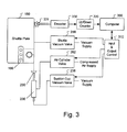
- Fig. 3 is a block diagram of the shuttle envelope feeder with vacuum suction cup assist, including valves and controlling mechanism, according to the first embodiment of the invention.
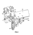
- Fig. 4 is a three-dimensional view of the shuttle envelope feeder, according to the first embodiment of the invention.
- Fig. 5 is a three-dimensional view of the shuttle envelope feeder, according to a second embodiment of the invention.
- Fig. 6 is a three-dimensional view of the shuttle envelope feeder, according to a third embodiment of the invention.
- Fig. 7 is a block diagram of the shuttle envelope feeder with vacuum suction cup assist, including valves and controlling mechanism, according to the third embodiment of the invention.
- a shuttle envelope feeder 200 comprises a shuttle plate 150 operable between a first position under an envelope stack and a second position that is at least partially remote from the envelope stack.
- the shuttle plate 150 has a surface 252 dimensioned for receipt of an envelope.
- the surface 252 has a leading edge 254.
- the shuttle plate 150 has an orifice 240 passing through the surface 252.
- the shuttle plate 150 further has a recessed area 280 formed in its surface 252 in proximity to the orifice 240 and extending at one end to the leading edge 254 of the surface 252.
- the recessed area 280 has at least one orifice 181 passing therethrough and in communication with a shuttle vacuum valve 256 (seen in Fig. 3) to form a vacuum gripping mechanism 180.
- the vacuum envelope feeder further comprises a suction cup 230 having an upper rim 232 and a lower neck 234.
- the lower neck 234 has an opening formed therein, which is connected to a hollow rod 233, the rod, in turn, is in communication with a suction cup vacuum valve 238 (seen in Fig. 3).
- the suction cup 230 is thus in cooperative engagement with an actuator or air cylinder 236, which, in turn, is in communication with an air cylinder valve 262 (seen in Fig. 3).
- the actuator 236 moves the rod 233 and thus the suction cup 230 between an extended position that passes the suction cup through the orifice 240 in the shuttle plate 150 and a retracted position so that the suction cup resides inside the orifice and the upper rim 232 of the suction cup 230 is at least flush with the surface 252.
- the orifice 240 is dimensioned so that the suction cup 230 and/or the hollow rod 233 is not in contact with the orifice and not in obstruction with the movement of the shuttle plate.
- the vacuum envelope feeder also comprises a controlling mechanism including a computer 300 (or other programmable logical device) that coordinates an input/output control module 310 by monitoring the shuttle position via an up/down counter 320 in communication with an encoder 330 equipped with a position sensor 331 via a position circuit.
- the position circuit may consist of an up/down counter 320 in communication with an encoder 330 equipped with a position sensor 331 or an input port that allows the computer to directly read position of the shuttle plate from an absolute encoder or positional resolver.
- the actuator 236 moves the cup 230 toward the extended position and the suction cup vacuum valve 238 is activated (vacuum ON). Once the suction cup 230 reaches the extended position, a small time delay is used to insure that the suction cup 230 attaches to an envelope at the bottom of the envelope stack. The actuator then pulls the suction cup 230 toward the retracted position.
- the shuttle vacuum valve 256 is activated to allow the envelope gripping mechanism 180 to acquire the envelope.
- the suction cup vacuum valve can be deactivated (turned OFF) immediately after envelope is acquired.
- the shuttle plate 150 then moves toward the second position with the envelope going under a stripper bar 170 so that it is separated from the remaining envelopes in the envelope stack.
- clamps 190 see Fig. 1
- the shuttle feeder returns to its initial position, ready to acquire the next envelope.
- the computer 300 stores parameters such as the real-time shuttle position acquired via a position circuit with an position encoder or resolver 330 having a position sensor 331, envelope width, the distance D between the leading edge 254 of the shuttle plate and the center of the suction cup 230, air valve latencies, air cylinder latencies and system latencies. Based on the parameters pre-stored in the computer and acquired by the computer, the computer calculates a time sequence for actuating the suction cup and activating/deactivating the suction cup vacuum valve for the input/output control module 310 to coordinate the operation of the valves.
- the specific computer programming and controlling procedures of vacuum and air valves according to such specific parameters is known to people of ordinary skills in the art.
- the shuttle plate 150 comprises an orifice 240 passing through the surface 252.
- the shuttle plate 150 and the actuator 236 that supports the suction cup 230 are mounted rigidly on a frame 392.
- the frame moves from a first position to a second position by a rolling mechanism 394 on a horizontal bar 396.
- the orifice 240 is dimensioned larger than the outer dimension of the suction cup 230 so as to allow the suction cup to reside inside the orifice when the suction cup is in the retracted position.
- the shuttle plate 150 comprises an orifice 440 passing through the surface 252.
- the shuttle plate 150 and the actuator 436 that supports the suction cup 430 are mounted on two separate frames 392 and 498, respectively.
- the shuttle plate 150 mounted on the frame 392 moves from a first position to a second position by a rolling mechanism 394 on a horizontal bar 396.
- Frame 498 is stationary in relationship to the insertion station.
- the orifice 440 is in an elongated shape and is dimensioned larger than the outer dimension of the suction cup 430.
- the suction cup 430 resides inside the orifice when it is in the retracted position, and the suction cup is not in obstruction with the movement of the shuttle plate.
- the shuttle plate 150 comprises a first orifice 240 and a second orifice 440, both passing through the surface 252.
- the shuttle plate 150 and a first actuator 236 that supports a first suction cup 230 are mounted rigidly on a frame 392.
- a second actuator 436 that supports a second suction cup 430 is mounted on a frame 498.
- Frame 392 moves from a first position to a second position by a rolling mechanism 394 on a horizontal bar 396.
- Frame 498 is stationary in relationship to the mail insertion station.
- the first orifice 240 is dimensioned larger than the outer dimension of the first suction cup 230 so as to allow the first suction cup to reside inside the orifice when the first suction cup is in the retracted position.
- the second orifice 440 is in elongated shape and is dimensioned larger than the outer dimension of the second suction cup 430.
- the second suction cup 430 resides inside the second orifice 440 when the second suction cup is in the retracted position, and the second suction cup is not in obstruction with the movement of the shuttle plate.
- the first suction cup 230 is connected via a hollow rod to a first suction cup vacuum valve 238.
- a first actuator or air cylinder 236 that moves the first suction cup is in communication with a first air cylinder valve 262.
- the second suction cup 430 is connected via a hollow rod to a second suction cup vacuum valve 438.
- a second actuator or air cylinder 436 that moves the second suction cup is in communication with a second air cylinder valve 462.
- a computer 300 (or other programmable logical device) stores parameters such as the real-time shuttle position acquired via a up/down counter 320 in communication with a position encoder 330 having a position sensor 331, envelope width, the distance D between the leading edge 254 of the shuttle plate 150 to the center of the first suction cup 230, air valve latencies, air cylinder latencies and system latencies. Based on the parameters pre-stored in the computer and acquired by the computer, the computer calculates a time sequence for actuating the suction cups and activating/deactivating the suction cup vacuum valves for the input/output control module 310' to coordinate the operation of the valves.
- the vacuum suction mechanism may be replaced by other mechanisms that temporarily acquire an envelope through a moving part that is in cooperation with the shuttle plate.
- Examples include a receiving member in place of the suction cup that is charged with static electrons. The static electrons attract the envelope at the bottom of the envelope stack when the receiving member is in close proximity of the envelope, thereby temporarily securing the envelope onto the receiving member.
- the present invention relates to a shuttle envelope feeder with a vacuum suction cup assist mechanism.
- the present invention has the advantage of acquiring cupped or bent envelopes in an envelope stack in a very repeatable fashion.
- the suction cup controlling mechanism is separable from the controlling mechanism of the shuttle plate.
- One or more suction cups can be individually enabled or disabled according to the conditions of the envelopes in the envelope stack.
Landscapes
- Engineering & Computer Science (AREA)
- Mechanical Engineering (AREA)
- Sheets, Magazines, And Separation Thereof (AREA)
- Supplying Of Containers To The Packaging Station (AREA)
Abstract
Description
- This invention generally relates to machines that operate at a very high speed to insert sheets of paper or other items into envelopes. More particularly, it relates to a shuttle envelope feeder that transports the envelopes to be inserted.
- Machines for automatically inserting items such as sheets of paper into envelopes are known in the art. A state-of-the-art mail inserting machine such as the Flowmaster™ FX14 manufactured by Pitney Bowes of Stamford, Connecticut, USA can perform 12,000 insertions per hour when properly maintained and adjusted.
- A typical high-speed inserting machine comprises several modules. A first module transports an elongate horizontal queue of envelopes to an envelope stack. An envelope feeder located at the bottom of the envelope stack delivers the envelopes one by one to an envelope insertion station. A second module delivers individual groups of stacked sheets to the envelope insertion station. A third module, the envelope insertion station, includes clamps carried by an elongate sprocket chain that sequentially receives envelopes from the envelope feeder and pulls them past an envelope flap-opening structure and a sheet inserting structure where the envelopes are opened and inserted with stacked sheets. The envelopes are then pulled past an envelope closing structure and an envelope sealing structure before been ejected to a collection station.
- Fig. 1 schematically shows an arrangement of a prior art envelope feeder. The envelope feeder comprises a
shuttle plate 150 that moves back and forth (direction shown as doted arrow line 152) to transportenvelopes 140 to be grasped byclamps 190 on anelongate sprocket chain 160 of the insertion station. The shuttle plate has a recessed area in which avacuum gripping mechanism 180 is arranged. The negative pressure form thevacuum gripping mechanism 180 pulls the part of the envelope directly above the recessed area toward the recessed area so as to temporarily secure the envelope to the upper surface of the shuttle plate. When the shuttle moves toward thesprocket chain 160, astripper bar 170 located above the recessed area separates the secured bottom envelope from the envelope stack and allows it to move forward with the shuttle. - The vacuum envelope feeder of the above arrangement works well when envelopes are substantially flat. If, however, some of the envelopes are significantly curled or bent, the shuttle vacuum may not have sufficient suction to pull down these envelopes, causing a failure in the shuttle feed.
- Some methods have been proposed in order to solve the above problem. One is to add pressure to the top of the envelope stack to help flatten the envelopes. This method is somewhat ineffective, because an improperly applied stack pressure can also cause a failure in the shuttle feed or multiple envelope feedings.
- Another method uses a thumper to add stack pressure when the shuttle vacuum is turned on. When the shuttle moves forward, the thumper retracts and the shuttle vacuum holds the curled envelope. The disadvantages of this method are that the thumper disturbs the stack and the flow of envelopes from the envelope transport module, and it requires constant mechanical adjustment.
- What is needed is a vacuum shuttle feeder that is capable of feeding curled envelopes without failure. Preferably, the operation of such feeder will not interfere with existing configuration of the envelope stack or envelope flow. In addition, the feeder should be operative over a wide range of envelope dimensions.
- The invention provides an envelope feeder in an envelope insertion machine for removing envelopes from an envelope stack. The envelope feeder comprises a shuttle plate and a suction cup assembly.
- The shuttle plate is operable between a first position under the envelope stack and a second position at least partially remote from the envelope stack. The shuttle plate has an orifice passing through its upper surface, and an envelope gripping mechanism that is in communication with a shuttle vacuum valve.
- The suction cup assembly comprises a suction cup that has an upper rim and a lower neck with an opening formed therein, the opening is connected to a hollow rod. The rod, in turn, is in communication with a suction cup vacuum valve. An actuator engages the suction cup and moves the suction cup between an extended position that passes through the orifice in the shuttle plate to a retracted position that the upper rim of the suction cup is at least flush with the upper surface of the shuttle plate.
- The suction cup vacuum valve is activated at least when the suction cup is in the extended position so that the suction cup attaches to an envelope at the bottom of the envelope stack. The suction cup pulls the envelope toward the upper surface of the shuttle plate as the actuator moves from the extended position to the retracted position.
- The shuttle vacuum valve is activated at least when the envelope is pulled toward the upper surface of the shuttle plate. By doing so, the envelope is retained by the envelope gripping mechanism, allowing the shuttle plate to remove the envelope from the envelope stack as the shuttle plate moves to its second position.
- The invention further provides a method for an above-described envelope feeder in an envelope insertion machine to remove an envelope from an envelope stack. The method comprising the steps of: placing the shuttle plate in the first position, moving the suction cup between the retracted position that is at least flush with the upper surface of the shuttle plate and the extended position that is in contact with an envelope at the bottom of the envelope stack, and controlling the air pressure within the suction cup so that the suction cup has a lower air pressure than the ambient air pressure when the suction cup is in the extended position and while it moves from the extended position to the retracted position.
- In accordance with the method, the envelope at the bottom of the envelope stack is pulled down toward the upper surface of the shuttle plate so as to facilitate the acquisition of said envelope by the envelope gripping mechanism.
- The above and other objects, features and advantages of the invention will become apparent from a consideration of the subsequent detailed description presented in connection with accompanying drawings, in which:
- Fig. 1 is a schematic illustration of a prior art shuttle feeder part of an envelope insertion station.
- Fig. 2A is a schematic top view of a shuttle envelope feeder with vacuum suction assist, according to a first embodiment of the invention.
- Fig. 2B is a schematic cross-sectional view of a shuttle envelope feeder with vacuum suction assist, taken along
line 2B in Fig. 2A, according to the first embodiment of the invention. - Fig. 3 is a block diagram of the shuttle envelope feeder with vacuum suction cup assist, including valves and controlling mechanism, according to the first embodiment of the invention.
- Fig. 4 is a three-dimensional view of the shuttle envelope feeder, according to the first embodiment of the invention.
- Fig. 5 is a three-dimensional view of the shuttle envelope feeder, according to a second embodiment of the invention.
- Fig. 6 is a three-dimensional view of the shuttle envelope feeder, according to a third embodiment of the invention.
- Fig. 7 is a block diagram of the shuttle envelope feeder with vacuum suction cup assist, including valves and controlling mechanism, according to the third embodiment of the invention.
- Referring to Fig. 2A, a
shuttle envelope feeder 200, according to the present invention comprises ashuttle plate 150 operable between a first position under an envelope stack and a second position that is at least partially remote from the envelope stack. Theshuttle plate 150 has asurface 252 dimensioned for receipt of an envelope. Thesurface 252 has a leadingedge 254. Theshuttle plate 150 has anorifice 240 passing through thesurface 252. Theshuttle plate 150 further has arecessed area 280 formed in itssurface 252 in proximity to theorifice 240 and extending at one end to the leadingedge 254 of thesurface 252. Therecessed area 280 has at least oneorifice 181 passing therethrough and in communication with a shuttle vacuum valve 256 (seen in Fig. 3) to form avacuum gripping mechanism 180. - Referring now to Fig. 2B, the vacuum envelope feeder further comprises a
suction cup 230 having anupper rim 232 and alower neck 234. Thelower neck 234 has an opening formed therein, which is connected to ahollow rod 233, the rod, in turn, is in communication with a suction cup vacuum valve 238 (seen in Fig. 3). - The
suction cup 230 is thus in cooperative engagement with an actuator orair cylinder 236, which, in turn, is in communication with an air cylinder valve 262 (seen in Fig. 3). Theactuator 236 moves therod 233 and thus thesuction cup 230 between an extended position that passes the suction cup through theorifice 240 in theshuttle plate 150 and a retracted position so that the suction cup resides inside the orifice and theupper rim 232 of thesuction cup 230 is at least flush with thesurface 252. Theorifice 240 is dimensioned so that thesuction cup 230 and/or thehollow rod 233 is not in contact with the orifice and not in obstruction with the movement of the shuttle plate. - Referring further to Fig. 3, the vacuum envelope feeder also comprises a controlling mechanism including a computer 300 (or other programmable logical device) that coordinates an input/
output control module 310 by monitoring the shuttle position via an up/down counter 320 in communication with anencoder 330 equipped with aposition sensor 331 via a position circuit. The position circuit may consist of an up/down counter 320 in communication with anencoder 330 equipped with aposition sensor 331 or an input port that allows the computer to directly read position of the shuttle plate from an absolute encoder or positional resolver. - With the
shuttle plate 150 at the first position and the trailing edge of the previous envelope off of thesuction cup 230, theactuator 236 moves thecup 230 toward the extended position and the suctioncup vacuum valve 238 is activated (vacuum ON). Once thesuction cup 230 reaches the extended position, a small time delay is used to insure that thesuction cup 230 attaches to an envelope at the bottom of the envelope stack. The actuator then pulls thesuction cup 230 toward the retracted position. - Once the
suction cup 230 reaches the retracted position, theshuttle vacuum valve 256 is activated to allow theenvelope gripping mechanism 180 to acquire the envelope. The suction cup vacuum valve can be deactivated (turned OFF) immediately after envelope is acquired. Theshuttle plate 150 then moves toward the second position with the envelope going under astripper bar 170 so that it is separated from the remaining envelopes in the envelope stack. After clamps 190 (see Fig. 1) on the mail insertion station have grasped the envelope, the shuttle feeder returns to its initial position, ready to acquire the next envelope. - The
computer 300 stores parameters such as the real-time shuttle position acquired via a position circuit with an position encoder orresolver 330 having aposition sensor 331, envelope width, the distance D between theleading edge 254 of the shuttle plate and the center of thesuction cup 230, air valve latencies, air cylinder latencies and system latencies. Based on the parameters pre-stored in the computer and acquired by the computer, the computer calculates a time sequence for actuating the suction cup and activating/deactivating the suction cup vacuum valve for the input/output control module 310 to coordinate the operation of the valves. The specific computer programming and controlling procedures of vacuum and air valves according to such specific parameters is known to people of ordinary skills in the art. - In a first embodiment of the invention as shown in Fig.4, the
shuttle plate 150 comprises anorifice 240 passing through thesurface 252. Theshuttle plate 150 and theactuator 236 that supports thesuction cup 230 are mounted rigidly on aframe 392. The frame moves from a first position to a second position by arolling mechanism 394 on ahorizontal bar 396. Theorifice 240 is dimensioned larger than the outer dimension of thesuction cup 230 so as to allow the suction cup to reside inside the orifice when the suction cup is in the retracted position. - In a second embodiment of the invention as shown in Fig. 5, the
shuttle plate 150 comprises anorifice 440 passing through thesurface 252. Theshuttle plate 150 and theactuator 436 that supports thesuction cup 430 are mounted on twoseparate frames shuttle plate 150 mounted on theframe 392 moves from a first position to a second position by arolling mechanism 394 on ahorizontal bar 396.Frame 498 is stationary in relationship to the insertion station. Theorifice 440 is in an elongated shape and is dimensioned larger than the outer dimension of thesuction cup 430. Thesuction cup 430 resides inside the orifice when it is in the retracted position, and the suction cup is not in obstruction with the movement of the shuttle plate. - In a third and preferred embodiment of the invention as shown in Fig. 6, the
shuttle plate 150 comprises afirst orifice 240 and asecond orifice 440, both passing through thesurface 252. Theshuttle plate 150 and afirst actuator 236 that supports afirst suction cup 230 are mounted rigidly on aframe 392. Asecond actuator 436 that supports asecond suction cup 430 is mounted on aframe 498.Frame 392 moves from a first position to a second position by arolling mechanism 394 on ahorizontal bar 396.Frame 498 is stationary in relationship to the mail insertion station. - The
first orifice 240 is dimensioned larger than the outer dimension of thefirst suction cup 230 so as to allow the first suction cup to reside inside the orifice when the first suction cup is in the retracted position. Thesecond orifice 440 is in elongated shape and is dimensioned larger than the outer dimension of thesecond suction cup 430. Thesecond suction cup 430 resides inside thesecond orifice 440 when the second suction cup is in the retracted position, and the second suction cup is not in obstruction with the movement of the shuttle plate. - As shown in Fig. 7, the
first suction cup 230 is connected via a hollow rod to a first suctioncup vacuum valve 238. A first actuator orair cylinder 236 that moves the first suction cup is in communication with a firstair cylinder valve 262. Thesecond suction cup 430 is connected via a hollow rod to a second suctioncup vacuum valve 438. A second actuator orair cylinder 436 that moves the second suction cup is in communication with a secondair cylinder valve 462. - A computer 300 (or other programmable logical device) stores parameters such as the real-time shuttle position acquired via a up/down counter 320 in communication with a
position encoder 330 having aposition sensor 331, envelope width, the distance D between theleading edge 254 of theshuttle plate 150 to the center of thefirst suction cup 230, air valve latencies, air cylinder latencies and system latencies. Based on the parameters pre-stored in the computer and acquired by the computer, the computer calculates a time sequence for actuating the suction cups and activating/deactivating the suction cup vacuum valves for the input/output control module 310' to coordinate the operation of the valves. - In an alternative embodiment of the invention, the vacuum suction mechanism may be replaced by other mechanisms that temporarily acquire an envelope through a moving part that is in cooperation with the shuttle plate. Examples include a receiving member in place of the suction cup that is charged with static electrons. The static electrons attract the envelope at the bottom of the envelope stack when the receiving member is in close proximity of the envelope, thereby temporarily securing the envelope onto the receiving member.
- In summary, the present invention relates to a shuttle envelope feeder with a vacuum suction cup assist mechanism. The present invention has the advantage of acquiring cupped or bent envelopes in an envelope stack in a very repeatable fashion. The suction cup controlling mechanism is separable from the controlling mechanism of the shuttle plate. One or more suction cups can be individually enabled or disabled according to the conditions of the envelopes in the envelope stack.
- Although the invention has been described and illustrated with respect to exemplary embodiments thereof, the foregoing and various other additions and omissions may be made therein without departing from the spirit and scope of the present invention.
Claims (12)
- An envelope feeder in an envelope insertion machine for removing envelopes from an envelope stack, comprising:a shuttle plate operable between a first position under said envelope stack and a second position at least partially remote from the envelope stack, the shuttle plate having a surface dimensioned for receipt of an envelope, said surface having a leading edge, the shuttle plate having a first orifice passing through said surface, the shuttle plate further having an envelope gripping mechanism extended to the leading edge and in communication with a shuttle vacuum valve;a first suction cup having an upper rim and a lower neck with an opening formed therein, said first opening connecting to a first hollow rod and said first hollow rod in communication with a first vacuum valve;a first actuator in cooperative engagement with the first suction cup for moving the first suction cup between an extended position that passes through the first orifice in the shuttle plate to a retracted position where the upper rim is at least flush with the surface;means for activating the first vacuum valve at least when the first suction cup is in the extended position so that the first suction cup attaches to an envelope at the bottom of the envelope stack and so that the first suction cup pulls said envelope toward the surface of the shuttle plate as the first actuator moves from the extended position to the retracted position; andmeans for activating the shuttle vacuum valve at least when said envelope is pulled toward the surface of the shuttle plate so that the envelope is retained by the envelope gripping mechanism; thereby allowing the shuttle plate to remove said envelope from the envelope stack as the shuttle plate moves to its second position.
- The envelope feeder according to claim 1, wherein the first suction cup and the first actuator are translationally stationary in relationship to the shuttle plate, and the first orifice is dimensioned so that the first suction cup resides inside the first orifice when the suction cup is in the retracted position.
- The envelope feeder according to claim 1, wherein the first suction cup and the first actuator are translationally stationary in relationship to the envelope insertion machine, and the first orifice is dimensioned so that the first suction cup resides inside the first orifice when the suction cup is in the retracted position in a manner so that the first suction cup is not in obstruction with the movement of the shuttle plate.
- The envelope feeder according to claim 1, further comprising:a second orifice passing through said surface of said shuttle plate;a second suction cup having an upper rim and a lower neck with an opening formed therein, said opening connecting to a second hollow rod and said second hollow rod in communication with a second vacuum valve;a second actuator in cooperative engagement with the second suction cup for moving the second suction cup between an extended position that passes through the second orifice in the shuttle plate to a retracted position where the upper rim is at least flush with the surface;means for activating the second vacuum valve at least when the second suction cup is in the extended position so that the second suction cup attaches to an envelope at the bottom of the envelope stack and so that the second suction cup pulls said envelope toward the surface of the shuttle plate as the second actuator moves from the extended position to the retracted position.
- The envelope feeder according to claim 4, wherein
the first suction cup and the first actuator are translationally stationary in relationship to the shuttle plate, and the first orifice is dimensioned so that the first suction cup resides inside the first orifice when it is in the retracted position; and
the second suction cup and the second actuator are translationally stationary in relationship to the envelope insertion machine, and the second orifice is dimensioned so that the second suction cup moves within the second orifice when it is in the retracted position in a manner so that the second suction cup is not in obstruction with the movement of the shuttle plate. - The envelope feeder according to claim 1, wherein the means for activating the first vacuum valve includes an input/output control module in communication with a programmable logical device for controllably activating the first vacuum valve.
- The envelope feeder according to claim 6, further comprising a first air cylinder valve connected to the first actuator, said first air cylinder valve controllable by said input/output control module.
- The envelope feeder according to claim 1, wherein the means for activating the shuttle vacuum valve includes an input/output control module in communication with a programmable logical device for controllably activating the shuttle vacuum valve.
- The envelope feeder according to claim 4, wherein the means for activating the second vacuum valve includes an input/output control module in communication with a programmable logical device for controllably activating the second vacuum valve.
- The envelope feeder according to claim 9, further comprising a second air cylinder valve connected to the second actuator, said second air cylinder valve controllable by said input/output control module.
- A method for an envelope feeder in an envelope insertion machine to remove an envelope from an envelope stack, said envelope feeder having a suction cup operable between an extended position and a retracted position, and a shuttle plate operable between a first position under the envelope stack and a second position at least partially remote from said envelope stack, said shuttle plate having a surface dimensioned for receipt of an envelope, an orifice passing through the shuttle plate, and an envelope gripping mechanism in communication with a shuttle vacuum valve, said method comprising the steps of:placing the shuttle plate in the first position,moving the suction cup positioned within said orifice between a retracted position that is at least flush with the surface of the shuttle plate and an extended position that is in contact with an envelope at the bottom of the envelope stack, andcontrolling the air pressure within the suction cup so that the suction cup has a lower air pressure than the ambient air pressure when the suction cup is in the extended position and while it moves from the extended position to the retracted position;whereby the envelope at the bottom of the envelope stack is pulled down toward the surface of the shuttle plate so as to facilitate the acquisition of said envelope by the envelope gripping mechanism.
- A method for an envelope feeder in an envelope insertion machine to remove an envelope from an envelope stack, said envelope feeder having a first suction cup operable between an extended position and a retracted position, a second suction cup operable between an extended position and a retracted position, and a shuttle plate operable between a first position under the envelope stack and a second position at least partially remote from said envelope stack, said shuttle plate having a surface dimensioned for receipt of an envelope, a first and a second orifice each passing through the shuttle plate, and an envelope gripping mechanism in communication with a shuttle vacuum valve, said method comprising the steps of:placing the shuttle plate in the first position,moving the first suction cup positioned within said first orifice between a retracted position that is at least flush with the surface of the shuttle plate and an extended position that is in contact with an envelope at the bottom of the envelope stack, andcontrolling the air pressure within the first suction cup so that the first suction cup has a lower air pressure than the ambient air pressure when the first suction cup is in the extended position and while it moves from the extended position to the retracted position;moving the second suction cup positioned within said second orifice between a retracted position that is at least flush with the surface of the shuttle plate and an extended position that is in contact with an envelope at the bottom of the envelope stack, andcontrolling the air pressure within the second suction cup so that the second suction cup has a lower air pressure than the ambient air pressure when the second suction cup is in the extended position and while it moves from the extended position to the retracted position;whereby the envelope at the bottom of the envelope stack is pulled down toward the surface of the shuttle plate so as to facilitate the acquisition of said envelope by the envelop gripping mechanism.
Applications Claiming Priority (1)
| Application Number | Priority Date | Filing Date | Title |
|---|---|---|---|
| US11/188,023 US20070018377A1 (en) | 2005-07-22 | 2005-07-22 | Shuttle envelope feeder with suction cup assist |
Publications (2)
| Publication Number | Publication Date |
|---|---|
| EP1746058A1 true EP1746058A1 (en) | 2007-01-24 |
| EP1746058B1 EP1746058B1 (en) | 2009-09-09 |
Family
ID=37309587
Family Applications (1)
| Application Number | Title | Priority Date | Filing Date |
|---|---|---|---|
| EP06014912A Expired - Lifetime EP1746058B1 (en) | 2005-07-22 | 2006-07-18 | Shuttle envelope feeder with suction cup assist and corresponding method |
Country Status (4)
| Country | Link |
|---|---|
| US (1) | US20070018377A1 (en) |
| EP (1) | EP1746058B1 (en) |
| CA (1) | CA2553308A1 (en) |
| DE (1) | DE602006009028D1 (en) |
Cited By (1)
| Publication number | Priority date | Publication date | Assignee | Title |
|---|---|---|---|---|
| EP3059192A1 (en) * | 2015-02-20 | 2016-08-24 | Pitney Bowes Inc. | Envelope feeder with selective suction cup assist |
Families Citing this family (1)
| Publication number | Priority date | Publication date | Assignee | Title |
|---|---|---|---|---|
| CN113799157B (en) * | 2020-06-17 | 2025-05-23 | 合肥美亚光电技术股份有限公司 | Combined type holding device and have its pick-up robot |
Citations (2)
| Publication number | Priority date | Publication date | Assignee | Title |
|---|---|---|---|---|
| US3510126A (en) * | 1966-07-29 | 1970-05-05 | Bobst Fils Sa J | Mechanism for feeding a sheet material to a processing machine |
| US3844551A (en) * | 1972-10-11 | 1974-10-29 | Bell & Howell Co | Sheet shuttle feed |
-
2005
- 2005-07-22 US US11/188,023 patent/US20070018377A1/en not_active Abandoned
-
2006
- 2006-07-18 DE DE602006009028T patent/DE602006009028D1/en not_active Expired - Lifetime
- 2006-07-18 EP EP06014912A patent/EP1746058B1/en not_active Expired - Lifetime
- 2006-07-21 CA CA002553308A patent/CA2553308A1/en not_active Abandoned
Patent Citations (2)
| Publication number | Priority date | Publication date | Assignee | Title |
|---|---|---|---|---|
| US3510126A (en) * | 1966-07-29 | 1970-05-05 | Bobst Fils Sa J | Mechanism for feeding a sheet material to a processing machine |
| US3844551A (en) * | 1972-10-11 | 1974-10-29 | Bell & Howell Co | Sheet shuttle feed |
Cited By (2)
| Publication number | Priority date | Publication date | Assignee | Title |
|---|---|---|---|---|
| EP3059192A1 (en) * | 2015-02-20 | 2016-08-24 | Pitney Bowes Inc. | Envelope feeder with selective suction cup assist |
| US10087024B2 (en) | 2015-02-20 | 2018-10-02 | DMT Solutions Global Corp. | Envelope feeder with selective suction cup assist |
Also Published As
| Publication number | Publication date |
|---|---|
| EP1746058B1 (en) | 2009-09-09 |
| CA2553308A1 (en) | 2007-01-22 |
| US20070018377A1 (en) | 2007-01-25 |
| DE602006009028D1 (en) | 2009-10-22 |
Similar Documents
| Publication | Publication Date | Title |
|---|---|---|
| US4369962A (en) | Apparatus for feeding sheets | |
| US5322012A (en) | Method and system for the lateral alignment of sheets | |
| EP1220329A3 (en) | Sheet set and output lead wire set apparatuses for sealing and sealing apparatus | |
| US9969156B2 (en) | Transverse sheet withdrawal brake | |
| EP1746058B1 (en) | Shuttle envelope feeder with suction cup assist and corresponding method | |
| EP1894868B1 (en) | Sheet separation method, sheet separation mechanism and sheet feeder | |
| US4669716A (en) | Method and device for deflecting a sheet prior to feeding | |
| EP1911704A2 (en) | Apparatus and methods for registering sheet articles | |
| EP2033916B1 (en) | Feed apparatus for printing press | |
| US5971385A (en) | Envelope feeder and integral flap opening device | |
| JP2568437Y2 (en) | Paper suction device | |
| GB2195618A (en) | Separating sheet material | |
| EP3059192B1 (en) | Envelope feeder with selective suction cup assist | |
| US6364311B1 (en) | Negative-pressure control for a lateral pulling device | |
| US2328943A (en) | Means for registering sheets | |
| CN100393598C (en) | Apparatus and method for separating paper into sheets | |
| US7797914B2 (en) | Method and device for holding envelopes during insertion | |
| EP1795369A3 (en) | Jam tolerant mail inserter | |
| US20160243883A1 (en) | Envelope inserter with suction cup opening mechanism and improved insertion motion control | |
| DE102007005403A1 (en) | Sheet-separating suction device for feeder of sheet printing press, has drive device including stroke length adjusting device for fixing suction position by adjustment of length of stroke of cup along vertical running path | |
| JP4618849B2 (en) | Label adsorption device | |
| US20030056476A1 (en) | Envelope stripping apparatus | |
| CN110884922B (en) | Method for printing mailpieces individually fed from a stack to a printing press | |
| RU2170208C1 (en) | Method of and device for gripping and separation of upper sheet from pile and its further transportation | |
| CN203173544U (en) | Automatic paper-feeding device of cylinder forming machine |
Legal Events
| Date | Code | Title | Description |
|---|---|---|---|
| PUAI | Public reference made under article 153(3) epc to a published international application that has entered the european phase |
Free format text: ORIGINAL CODE: 0009012 |
|
| AK | Designated contracting states |
Kind code of ref document: A1 Designated state(s): AT BE BG CH CY CZ DE DK EE ES FI FR GB GR HU IE IS IT LI LT LU LV MC NL PL PT RO SE SI SK TR |
|
| AX | Request for extension of the european patent |
Extension state: AL BA HR MK YU |
|
| 17P | Request for examination filed |
Effective date: 20070723 |
|
| AKX | Designation fees paid |
Designated state(s): CH DE FR GB LI |
|
| RTI1 | Title (correction) |
Free format text: SHUTTLE ENVELOPE FEEDER WITH SUCTION CUP ASSIST AND CORRESPONDING METHOD |
|
| GRAP | Despatch of communication of intention to grant a patent |
Free format text: ORIGINAL CODE: EPIDOSNIGR1 |
|
| GRAS | Grant fee paid |
Free format text: ORIGINAL CODE: EPIDOSNIGR3 |
|
| GRAA | (expected) grant |
Free format text: ORIGINAL CODE: 0009210 |
|
| AK | Designated contracting states |
Kind code of ref document: B1 Designated state(s): CH DE FR GB LI |
|
| REG | Reference to a national code |
Ref country code: GB Ref legal event code: FG4D |
|
| REG | Reference to a national code |
Ref country code: CH Ref legal event code: NV Representative=s name: E. BLUM & CO. AG PATENT- UND MARKENANWAELTE VSP Ref country code: CH Ref legal event code: EP |
|
| REF | Corresponds to: |
Ref document number: 602006009028 Country of ref document: DE Date of ref document: 20091022 Kind code of ref document: P |
|
| PLBE | No opposition filed within time limit |
Free format text: ORIGINAL CODE: 0009261 |
|
| STAA | Information on the status of an ep patent application or granted ep patent |
Free format text: STATUS: NO OPPOSITION FILED WITHIN TIME LIMIT |
|
| 26N | No opposition filed |
Effective date: 20100610 |
|
| PGFP | Annual fee paid to national office [announced via postgrant information from national office to epo] |
Ref country code: CH Payment date: 20100726 Year of fee payment: 5 |
|
| PGFP | Annual fee paid to national office [announced via postgrant information from national office to epo] |
Ref country code: FR Payment date: 20100805 Year of fee payment: 5 |
|
| PGFP | Annual fee paid to national office [announced via postgrant information from national office to epo] |
Ref country code: GB Payment date: 20100726 Year of fee payment: 5 |
|
| REG | Reference to a national code |
Ref country code: CH Ref legal event code: PL |
|
| GBPC | Gb: european patent ceased through non-payment of renewal fee |
Effective date: 20110718 |
|
| REG | Reference to a national code |
Ref country code: FR Ref legal event code: ST Effective date: 20120330 |
|
| PG25 | Lapsed in a contracting state [announced via postgrant information from national office to epo] |
Ref country code: CH Free format text: LAPSE BECAUSE OF NON-PAYMENT OF DUE FEES Effective date: 20110731 Ref country code: LI Free format text: LAPSE BECAUSE OF NON-PAYMENT OF DUE FEES Effective date: 20110731 Ref country code: FR Free format text: LAPSE BECAUSE OF NON-PAYMENT OF DUE FEES Effective date: 20110801 |
|
| PG25 | Lapsed in a contracting state [announced via postgrant information from national office to epo] |
Ref country code: GB Free format text: LAPSE BECAUSE OF NON-PAYMENT OF DUE FEES Effective date: 20110718 |
|
| PGFP | Annual fee paid to national office [announced via postgrant information from national office to epo] |
Ref country code: DE Payment date: 20180727 Year of fee payment: 13 |
|
| REG | Reference to a national code |
Ref country code: DE Ref legal event code: R082 Ref document number: 602006009028 Country of ref document: DE Representative=s name: HOFFMANN - EITLE PATENT- UND RECHTSANWAELTE PA, DE Ref country code: DE Ref legal event code: R081 Ref document number: 602006009028 Country of ref document: DE Owner name: DMT SOLUTIONS GLOBAL CORP. (N.D.GES.D. STAATES, US Free format text: FORMER OWNER: PITNEY BOWES, INC., STAMFORD, CONN., US |
|
| REG | Reference to a national code |
Ref country code: DE Ref legal event code: R119 Ref document number: 602006009028 Country of ref document: DE |
|
| PG25 | Lapsed in a contracting state [announced via postgrant information from national office to epo] |
Ref country code: DE Free format text: LAPSE BECAUSE OF NON-PAYMENT OF DUE FEES Effective date: 20200201 |