EP1745878B1 - Injection nozzle for threading an electrode wire of an electrical discharge machine - Google Patents
Injection nozzle for threading an electrode wire of an electrical discharge machine Download PDFInfo
- Publication number
- EP1745878B1 EP1745878B1 EP05015941A EP05015941A EP1745878B1 EP 1745878 B1 EP1745878 B1 EP 1745878B1 EP 05015941 A EP05015941 A EP 05015941A EP 05015941 A EP05015941 A EP 05015941A EP 1745878 B1 EP1745878 B1 EP 1745878B1
- Authority
- EP
- European Patent Office
- Prior art keywords
- injection nozzle
- threading
- wire
- stainless steel
- ceramics
- Prior art date
- Legal status (The legal status is an assumption and is not a legal conclusion. Google has not performed a legal analysis and makes no representation as to the accuracy of the status listed.)
- Expired - Lifetime
Links
Images


Classifications
-
- B—PERFORMING OPERATIONS; TRANSPORTING
- B23—MACHINE TOOLS; METAL-WORKING NOT OTHERWISE PROVIDED FOR
- B23H—WORKING OF METAL BY THE ACTION OF A HIGH CONCENTRATION OF ELECTRIC CURRENT ON A WORKPIECE USING AN ELECTRODE WHICH TAKES THE PLACE OF A TOOL; SUCH WORKING COMBINED WITH OTHER FORMS OF WORKING OF METAL
- B23H7/00—Processes or apparatus applicable to both electrical discharge machining and electrochemical machining
- B23H7/02—Wire-cutting
- B23H7/08—Wire electrodes
- B23H7/10—Supporting, winding or electrical connection of wire-electrode
- B23H7/102—Automatic wire threading
-
- B—PERFORMING OPERATIONS; TRANSPORTING
- B23—MACHINE TOOLS; METAL-WORKING NOT OTHERWISE PROVIDED FOR
- B23H—WORKING OF METAL BY THE ACTION OF A HIGH CONCENTRATION OF ELECTRIC CURRENT ON A WORKPIECE USING AN ELECTRODE WHICH TAKES THE PLACE OF A TOOL; SUCH WORKING COMBINED WITH OTHER FORMS OF WORKING OF METAL
- B23H7/00—Processes or apparatus applicable to both electrical discharge machining and electrochemical machining
- B23H7/02—Wire-cutting
- B23H7/08—Wire electrodes
- B23H7/10—Supporting, winding or electrical connection of wire-electrode
- B23H7/105—Wire guides
Definitions
- the present invention relates to the improvement of an injection nozzle threading the wire electrode of a wire cut electric discharge machine from the upper wire guide, through the machining zone and aiming the entry of the lower wire guide.
- the wire electrode Before the start of machining, the wire electrode must be threaded in the working zone of the machine i.e. the wire extremity must be driven with great precision from the upper wire guidance head through a starting bore or a working gap in a work piece to be machined toward the lower wire guidance head.
- Automatic threading or re-threading is often used when the overall machining is composed of multiple closed contours, when closed contours are cut in several partial sections, when different wire electrodes are used, or when the wire accidentally breaks during operation due to local thermal overloading.
- the diameter of the electrode wire is less than 300 microns, up to 100 microns, and is only some micron smaller than the bore diameter of the wire guide members, automatically threading the wire through upper and lower wire guides is a rather difficult task.
- the initial step of the threading sequence consists in uniformly reducing the diameter of the electrode wire, upstream of the upper guide heads, by heating and stretching the wire over a length of about 300 mm.
- the heating and stretching zone is disposed upstream the upper head within a conduit surrounding the wire such as to insure uniform heating.
- the wire is thermally cut off at the bottom of its section of reduced diameter, thus forming the tip of a needle, while the downstream wire portion is disposed of by the wire feeding mechanism.
- the reduced diameter portion of the wire is successively introduced from above into the upper wire guide head, through a bore in the workpiece and through the lower wire guide, until the tip of the reduced diameter portion of the wire is caught by the wire feeding mechanism disposed downstream inside the lower head.
- Both wire guides are closed torus shaped pieces usually made of sapphire stone set inside a metallic support ring.
- the bore through the sapphire stone presents a narrow clearance of some microns, such as to limit to a minimum the permissible lateral play of the wire.
- the portion of the wire of reduced diameter is guided with the help of a free concentric fluid jet of high pressure water, to overcome the distance from the upper wire guide head toward the entry of the lower wire guide.
- the high pressure water jet comes out of a nozzle that is the most critical piece of the threading process.
- the said nozzle is made of ceramic i.e. a highly resistant material to abrasion and wear.
- Figure 1 illustrating an upper machining head of a wire electrical discharge machine, depicts the direct environment in which the aforesaid threading nozzle is built-in.
- a horizontal channel 2 receives the liquid under a 5 bar pressure intended to form a compact and calibrated threading jet 3 ousted downwards around the wire in the machining zone.
- the horizontal channel 2 emerges in a vertical cylindrical channel 4 of which all volume is occupied by the wire guide base 5, a complex part that fulfils several critical functions. It seats precisely fitted inside the masterpiece 1 and comprises in its center the feeder canal 6 conveying the wire electrode from top towards the wire guide 7 and intended also for cooling and wetting the wire guide and contact assembly by means of a separated fluid channel.
- Vertical grooves 8 in the periphery of the wire guide base 5 lead the pressurized liquid dedicated to the threading function to the annular chamber 9 which feeds the threading nozzle body 10 placed under the wire guide 7.
- the steel ring 21 support of the sapphire wire guide 7 seats embedded inside the threading nozzle body 10.
- the conduits inside the chamber 9 and the threading nozzle body 10 form particularly critical flow canals as the tiniest geometric imperfections may start turbulences and ultimately disrupt the axial symmetry of the outlet jet 3.
- the wire guide assembly i.e. the few parts in the vicinity of the wire guide 7, designed to be frequently disassembled, are contained in a cap 11 tightly and precisely locked against the wire guide base 5 by means of the screw thread 12.
- An O-ring 13 in the cap 11 ensures the sealing between the injection channel 8 intended to threading the wire and the injection room 14 for the watering of the working area during machining.
- the threading nozzle body 10 ( Figures 2a, 2b, 2c ) cast in one piece of ceramics has the overall form of a flat cylinder including six radial grooves 15 dug in its higher face 16 and building as many channels which concentrate the pressurized liquid in the center towards the thrust mouth 17 in the form of a reversed funnel.
- This type of threading nozzle exists for several diameters of threading jet.
- the bottleneck diameter of the thrust mouth 17 can be for example 0.5 mm, 0.8 mm or 1.8 mm.
- the thrust mouth 17 comprises two downwards open successive conical segments 18, 19.
- a first conical segment 18 of opening 30° which opens starting from the face 20 where converge the six radial grooves 15 and leads to a second conical segment 19 of opening 60° which in turn leads to the lower face 22 of the aforesaid flat cylinder constituting the threading nozzle body 10.
- a coaxial facing 23 is practiced inside the higher face 16 of the part, making it possible to embed the steel ring 21 support of the sapphire wire guide 7 (see Fig. 1 ) when the cap 11 is screwed on the wire guide base 5.
- facing 23 creates six sharp ridges 24 particularly fragile on which the steel ring 21 comes to rest.
- these ridges 24 break in shear; that causes disturbances in the flow of the liquid in the radial grooves 15 and unbalances the axial symmetry of the liquid channel 3 at exit. Consequently, the reliability of the threading operation will be considerably reduced.
- a more deplorable accident related to the brittleness of ceramics is the rupture of the part 10 when tightened too strongly if its lower face doesn't lie perfectly flat inside of the cap 11 on its bottom.
- the object of the present invention is to overcome the aforementioned weaknesses i.e. to prevent the breakage of the threading nozzle body 10 or the deterioration of the geometry of its leading channels 15.
- the solution adopted to solve the problem described hereinabove was to create as a replacement a composite piece in two parts, as described in Claim 1, out of stainless steel 25 on the one hand and ceramics 26 on the other hand.
- the two parts 25, 26 are assembled according to a method well known by the swiss company RAYMOND & Co SA in Lucens.
- the main question is here about an operation of assembly without adhesive substance which exploits the considerable forces deployed in metals by their cooling off.
- the ceramics inlay 26 is imprisoned inside the stainless steel crown 25 at the end of a particularly delicate operation of hooping during which the metal crown 25 is brought to thermally dilate before the ceramic inlay 26 is quickly introduced inside the calibrated boring. Then as soon as the two elements 25, 26 acquire the same temperature, the ceramics inlay 26, containing the thrust mouth 17, is strongly choked so that disassembling becomes impossible.
- Ceramics in the form of an inlay 26 hooped inside the stainless steel crown 25, was kept as a material for building the thrust mouth 17 because of its good wear resistance and its capacity to receive extremely precise geometrical forms. Aluminium oxydes Al2O3, Zirconium oxydes ZrO2, or Silicon Carbide SiC are the preferred ceramics for that application.
- vacuum hardened stainless steel with a minimum 58 HRC was selected to constitute the external crown 25 support of the ceramic inlay 26 as depicted in Claim 4.
- the fragile details 24 of the part 10 thus will consist of stainless steel and will no more be likely to break in shear.
- the principal body of the piece 25 will neither be likely to break in parts under the effect of tightening thusoccasioneeing the stable positioning of the threading nozzle.
Landscapes
- Chemical & Material Sciences (AREA)
- Chemical Kinetics & Catalysis (AREA)
- Electrochemistry (AREA)
- Engineering & Computer Science (AREA)
- Mechanical Engineering (AREA)
- Electrical Discharge Machining, Electrochemical Machining, And Combined Machining (AREA)
Abstract
Description
- The present invention relates to the improvement of an injection nozzle threading the wire electrode of a wire cut electric discharge machine from the upper wire guide, through the machining zone and aiming the entry of the lower wire guide.
- Such a nozzle is known from
US 6344624 which discloses in combination the features of the preamble ofclaim 1. - When cutting a workpiece in a traveling wire discharge electrical machine, some automatic operations require that the electrode wire be removed from the cut being carried out in the workpiece and rethreaded into another starting bore in the workpiece to proceed with another cut.
- Before the start of machining, the wire electrode must be threaded in the working zone of the machine i.e. the wire extremity must be driven with great precision from the upper wire guidance head through a starting bore or a working gap in a work piece to be machined toward the lower wire guidance head.
- Automatic threading or re-threading is often used when the overall machining is composed of multiple closed contours, when closed contours are cut in several partial sections, when different wire electrodes are used, or when the wire accidentally breaks during operation due to local thermal overloading.
- Because the diameter of the electrode wire is less than 300 microns, up to 100 microns, and is only some micron smaller than the bore diameter of the wire guide members, automatically threading the wire through upper and lower wire guides is a rather difficult task.
- The following documents deal with the issue of automatically threading the electrode wire and help to define the related domain:
CH 559 599 EP 0 206 041 ;DE 10 064 232 . - The initial step of the threading sequence consists in uniformly reducing the diameter of the electrode wire, upstream of the upper guide heads, by heating and stretching the wire over a length of about 300 mm. The heating and stretching zone is disposed upstream the upper head within a conduit surrounding the wire such as to insure uniform heating.
- In a following step the wire is thermally cut off at the bottom of its section of reduced diameter, thus forming the tip of a needle, while the downstream wire portion is disposed of by the wire feeding mechanism.
- The reduced diameter portion of the wire is successively introduced from above into the upper wire guide head, through a bore in the workpiece and through the lower wire guide, until the tip of the reduced diameter portion of the wire is caught by the wire feeding mechanism disposed downstream inside the lower head.
- Both wire guides are closed torus shaped pieces usually made of sapphire stone set inside a metallic support ring. In order to further increase the accurate positioning of the longitudinal axis of the wire, the bore through the sapphire stone presents a narrow clearance of some microns, such as to limit to a minimum the permissible lateral play of the wire.
- As soon as the tip of the upper wire portion comes down and springs out of the upper guide and during the whole threading operation, the portion of the wire of reduced diameter is guided with the help of a free concentric fluid jet of high pressure water, to overcome the distance from the upper wire guide head toward the entry of the lower wire guide.
- The high pressure water jet comes out of a nozzle that is the most critical piece of the threading process. To assure the great repetitive accuracy of its outlet the said nozzle is made of ceramic i.e. a highly resistant material to abrasion and wear.
-
Figure 1 , illustrating an upper machining head of a wire electrical discharge machine, depicts the direct environment in which the aforesaid threading nozzle is built-in. - In the masterpiece 1 a
horizontal channel 2 receives the liquid under a 5 bar pressure intended to form a compact and calibrated threadingjet 3 ousted downwards around the wire in the machining zone. - The
horizontal channel 2 emerges in a verticalcylindrical channel 4 of which all volume is occupied by thewire guide base 5, a complex part that fulfils several critical functions. It seats precisely fitted inside themasterpiece 1 and comprises in its center thefeeder canal 6 conveying the wire electrode from top towards thewire guide 7 and intended also for cooling and wetting the wire guide and contact assembly by means of a separated fluid channel.Vertical grooves 8 in the periphery of thewire guide base 5 lead the pressurized liquid dedicated to the threading function to theannular chamber 9 which feeds the threadingnozzle body 10 placed under thewire guide 7. Thesteel ring 21 support of thesapphire wire guide 7 seats embedded inside the threadingnozzle body 10. The conduits inside thechamber 9 and the threadingnozzle body 10 form particularly critical flow canals as the tiniest geometric imperfections may start turbulences and ultimately disrupt the axial symmetry of theoutlet jet 3. - The wire guide assembly i.e. the few parts in the vicinity of the
wire guide 7, designed to be frequently disassembled, are contained in acap 11 tightly and precisely locked against thewire guide base 5 by means of thescrew thread 12. An O-ring 13 in thecap 11 ensures the sealing between theinjection channel 8 intended to threading the wire and theinjection room 14 for the watering of the working area during machining. - The threading nozzle body 10 (
Figures 2a, 2b, 2c ) cast in one piece of ceramics has the overall form of a flat cylinder including sixradial grooves 15 dug in itshigher face 16 and building as many channels which concentrate the pressurized liquid in the center towards thethrust mouth 17 in the form of a reversed funnel. This type of threading nozzle exists for several diameters of threading jet. The bottleneck diameter of thethrust mouth 17 can be for example 0.5 mm, 0.8 mm or 1.8 mm. - Because it becomes worn, among other reasons, the threading
nozzle body 10 have to be replaced, in accordance to a procedure described in details in the customer documentation related to ROBOFIL® machines, available online from the control panel of the machines, particularly in the sections entitled "periodic maintenance" and "wear parts list" that sets out in particular the various critical parts involved in the threading operations. It also frequently occurs that the machine operator must vary the diameter of thethreading jet 3 because of the use of a thinner or thicker wire or because of a change of the diameter of the starting bores inside the workpiece. - The
thrust mouth 17 comprises two downwards open successiveconical segments conical segment 18 of opening 30° which opens starting from theface 20 where converge the sixradial grooves 15 and leads to a secondconical segment 19 of opening 60° which in turn leads to thelower face 22 of the aforesaid flat cylinder constituting the threadingnozzle body 10. - A coaxial facing 23 is practiced inside the
higher face 16 of the part, making it possible to embed thesteel ring 21 support of the sapphire wire guide 7 (seeFig. 1 ) when thecap 11 is screwed on thewire guide base 5. - The operation of facing 23 creates six
sharp ridges 24 particularly fragile on which thesteel ring 21 comes to rest. When the clamping force is not well proportioned, it can occur that theseridges 24 break in shear; that causes disturbances in the flow of the liquid in theradial grooves 15 and unbalances the axial symmetry of theliquid channel 3 at exit. Consequently, the reliability of the threading operation will be considerably reduced. - A more deplorable accident related to the brittleness of ceramics, is the rupture of the
part 10 when tightened too strongly if its lower face doesn't lie perfectly flat inside of thecap 11 on its bottom. - The object of the present invention is to overcome the aforementioned weaknesses i.e. to prevent the breakage of the threading
nozzle body 10 or the deterioration of the geometry of its leadingchannels 15. - One preferred embodiment is explained below with the aid of the figures.
-
Figure 1 is a cross section view through the upper machining head assembly of a ROBOFIL ® wire electrical discharge machine. -
Figure 2a is an upper view of a threadingnozzle body 10 casts in one piece of ceramics. -
Figure 2b is a cross section view of thesame piece 10 corresponding to the line A-A shown inFigure 2a . -
Figure 2c is a cross section view of thesame piece 10 corresponding to the line B-B shown inFigure 2a . -
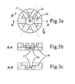
Figure 3a is an upper view of a composite threading nozzle body build in two parts object of the invention. -
Figure 3b is a cross section view of the same piece corresponding to the line A-A shown inFigure 3a . -
Figure 3c is a cross section view of the same piece corresponding to the line B-B shown inFigure 3a . - The solution adopted to solve the problem described hereinabove was to create as a replacement a composite piece in two parts, as described in
Claim 1, out ofstainless steel 25 on the one hand andceramics 26 on the other hand. The twoparts ceramics inlay 26 is imprisoned inside thestainless steel crown 25 at the end of a particularly delicate operation of hooping during which themetal crown 25 is brought to thermally dilate before theceramic inlay 26 is quickly introduced inside the calibrated boring. Then as soon as the twoelements ceramics inlay 26, containing thethrust mouth 17, is strongly choked so that disassembling becomes impossible. - Ceramics, in the form of an
inlay 26 hooped inside thestainless steel crown 25, was kept as a material for building thethrust mouth 17 because of its good wear resistance and its capacity to receive extremely precise geometrical forms. Aluminium oxydes Al2O3, Zirconium oxydes ZrO2, or Silicon Carbide SiC are the preferred ceramics for that application. - Because of its impact strength and its high resistance to corrosion, vacuum hardened stainless steel with a minimum 58 HRC was selected to constitute the
external crown 25 support of theceramic inlay 26 as depicted inClaim 4. - The
fragile details 24 of thepart 10 thus will consist of stainless steel and will no more be likely to break in shear. The principal body of thepiece 25 will neither be likely to break in parts under the effect of tightening thus garanteeing the stable positioning of the threading nozzle. - It must of course be understood that the embodiment described hereinabove, of a new threading nozzle intended to replace the
initial part 10, is not in any way limiting and that it can be adapted while at the same time assuring the compatibility i.e. respecting the dimensions and tolerances of the original pieces contributing to the threading process of the ROBOFIL ® machines. The simplest and economical way to ensure said compatibility is to duplicate dimensions and tolerances of theoriginal piece 10 made exclusively of ceramics which threading effectiveness was largely shown by at least ten years of experiments. Howewer it remains possible to design different shapes of a compatible replacement piece that would yield an effecive threading jet. For instance, theceramic inlay 26 containing thethrust mouth 17 may have a greater or lesser diameter. One can build the thrust mouth with cones of opening different from 30 or 60 degrees provided that the diameter of the threading jet is maintained and that it does not disperse before having reached the lower guide.
Claims (6)
- Injection nozzle (10) for threading an electrode wire of an electrical discharge machine, characterized in that the injection nozzle comprises a first part (25) and a second part (26), whereby the first part (25) is made of stainless steel and constitutes an external crown support for the centrally inlaid second part (26), which first part is made in form of a flat cylinder including six radial grooves (15) dug in its higher face (16) and building channels which concentrate a pressurized liquid in the center towards a thrust mouth and comprises a cylindrical hole for the second part (26) as inlay and whereby the second part (26) is made of ceramics and contains the thrust mouth (17) which has the form of a reversed funnel, comprising two downwards open successive conical segments (18, 19), and whereby a coaxial facing (23) is practiced inside the higher face (16) of the first part making it possible to embed a steel ring (21) support of a sapphire wire guide (7) therein.
- Injection nozzle (10) according to claim 1, characterized in that the first part (25) of the injection nozzle (10) is made of vacuum hardened stainless steel with a minimum 58 HRC.
- Injection nozzle (10) according to claim 2, characterized in that the second part (26) is made of Aluminiumoxyde Al2O3.
- Injection nozzle (10) according to claim 2, characterized in that the second part (26) is made of Zirconiumoxyde ZrO2.
- Injection nozzle (10) according to claim 2, characterized in that the second part (26) made of Silicon Carbide SiC.
- Injection nozzle (10) according to Claim 1 & 2, characterized in that the first part (25) and a second part (26) are assembled according to a method of hooping without adhesive substance which exploits the forces deployed in the stainless steel crown (25) by its cooling off, the ceramics inlay (26) being choked inside the stainless steel crown (25) so that disassembling becomes impossible.
Priority Applications (3)
| Application Number | Priority Date | Filing Date | Title |
|---|---|---|---|
| ES05015941T ES2366543T3 (en) | 2005-07-22 | 2005-07-22 | INJECTION NOZZLE FOR THREADING AN ELECTRODE WIRE FROM AN ELECTROEROSION MACHINE. |
| EP05015941A EP1745878B1 (en) | 2005-07-22 | 2005-07-22 | Injection nozzle for threading an electrode wire of an electrical discharge machine |
| AT05015941T ATE509725T1 (en) | 2005-07-22 | 2005-07-22 | NOZZLE FOR THREADING A WIRE ELECTRODE IN A WIRE CUTTING SPARK EROSIS DEVICE |
Applications Claiming Priority (1)
| Application Number | Priority Date | Filing Date | Title |
|---|---|---|---|
| EP05015941A EP1745878B1 (en) | 2005-07-22 | 2005-07-22 | Injection nozzle for threading an electrode wire of an electrical discharge machine |
Publications (2)
| Publication Number | Publication Date |
|---|---|
| EP1745878A1 EP1745878A1 (en) | 2007-01-24 |
| EP1745878B1 true EP1745878B1 (en) | 2011-05-18 |
Family
ID=35058653
Family Applications (1)
| Application Number | Title | Priority Date | Filing Date |
|---|---|---|---|
| EP05015941A Expired - Lifetime EP1745878B1 (en) | 2005-07-22 | 2005-07-22 | Injection nozzle for threading an electrode wire of an electrical discharge machine |
Country Status (3)
| Country | Link |
|---|---|
| EP (1) | EP1745878B1 (en) |
| AT (1) | ATE509725T1 (en) |
| ES (1) | ES2366543T3 (en) |
Families Citing this family (1)
| Publication number | Priority date | Publication date | Assignee | Title |
|---|---|---|---|---|
| CN101780573B (en) * | 2010-03-10 | 2011-07-20 | 苏州三光科技股份有限公司 | Nozzle device of linear cutting machine |
Family Cites Families (4)
| Publication number | Priority date | Publication date | Assignee | Title |
|---|---|---|---|---|
| CH559599A5 (en) | 1973-08-15 | 1975-03-14 | Agie Ag Ind Elektronik | |
| CH670784A5 (en) | 1985-06-28 | 1989-07-14 | Charmilles Technologies | |
| DE19882894T1 (en) * | 1998-10-16 | 2001-07-12 | Mitsubishi Electric Corp | Wire EDM device |
| DE10064232C1 (en) | 2000-12-22 | 2002-07-04 | Agie Sa | Device and method for guiding a machining electrode in a machine tool, in particular in a wire EDM machine |
-
2005
- 2005-07-22 AT AT05015941T patent/ATE509725T1/en not_active IP Right Cessation
- 2005-07-22 ES ES05015941T patent/ES2366543T3/en not_active Expired - Lifetime
- 2005-07-22 EP EP05015941A patent/EP1745878B1/en not_active Expired - Lifetime
Also Published As
| Publication number | Publication date |
|---|---|
| EP1745878A1 (en) | 2007-01-24 |
| ES2366543T3 (en) | 2011-10-21 |
| ATE509725T1 (en) | 2011-06-15 |
Similar Documents
| Publication | Publication Date | Title |
|---|---|---|
| KR940005396B1 (en) | Method and apparatus for machining | |
| US5340242A (en) | Chip-breaking toolholder with adjustable orifice cap | |
| JP6594900B2 (en) | Laser cutting nozzle with internal movable element and low dielectric constant sleeve | |
| JP4993770B2 (en) | Consumable electrode gas shield arc welding torch and power supply tip | |
| US7300233B2 (en) | Shaft tool and associated coolant/lubricant feeding point | |
| US4630802A (en) | Nozzle for injection lance | |
| US20100148454A1 (en) | Interface between a rotating shank tool and a lubricant transfer area in a tool holder | |
| CZ2020594A3 (en) | Machining tool | |
| CN108698060A (en) | The device of increasing material manufacturing is carried out by the injection and melting of powder | |
| KR920008729B1 (en) | Nozzle Assembly for Fluid Jet Cutting Systems | |
| EP2127502B1 (en) | Plasma cutting torch | |
| EP1745878A1 (en) | Injection nozzle involved in the process of threading the electrode wire of an electrical discharge machine | |
| EP2853349B1 (en) | Abrasive water jet cutting nozzle | |
| JP4263205B2 (en) | Combination of cutting torch and cutting nozzle for oxygen cutting torch system and cutting nozzle | |
| US7357607B2 (en) | Tool holder | |
| EP2796218A1 (en) | Drawing die tool and method of forming such a drawing die tool | |
| Kramar et al. | High performance manufacturing aspect of hard-to-machine materials | |
| EP0590093B1 (en) | Chip-breaking toolholder with adjustable orifice cap | |
| US6390349B1 (en) | Device and method for inducing a longitudinal force into a filament | |
| JP3002973U (en) | Tool holder that destroys inserts with adjustable orifice caps | |
| DE112015003776T5 (en) | Insulating guide for a plasma torch and spare part unit | |
| EP2853348B1 (en) | Water jet cutting focusing tube, water jet cutting mixing chamber and water jet cutting focusing tube with integrated mixing chamber | |
| EP4613409A1 (en) | Through flush guide for fast hole drilling with electrical discharge machining system | |
| GB2401335A (en) | Machine tool chuck provided for receiving a supply of pressurised fluid | |
| JP5192665B2 (en) | Electrode guide for electrodes for spark erosion of workpieces |
Legal Events
| Date | Code | Title | Description |
|---|---|---|---|
| PUAI | Public reference made under article 153(3) epc to a published international application that has entered the european phase |
Free format text: ORIGINAL CODE: 0009012 |
|
| AK | Designated contracting states |
Kind code of ref document: A1 Designated state(s): AT BE BG CH CY CZ DE DK EE ES FI FR GB GR HU IE IS IT LI LT LU LV MC NL PL PT RO SE SI SK TR |
|
| AX | Request for extension of the european patent |
Extension state: AL BA HR MK YU |
|
| 17P | Request for examination filed |
Effective date: 20070508 |
|
| 17Q | First examination report despatched |
Effective date: 20070713 |
|
| AKX | Designation fees paid |
Designated state(s): AT BE BG CH CY CZ DE DK EE ES FI FR GB GR HU IE IS IT LI LT LU LV MC NL PL PT RO SE SI SK TR |
|
| RTI1 | Title (correction) |
Free format text: INJECTION NOZZLE FOR THREADING AN ELECTRODE WIRE OF AN ELECTRICAL DISCHARGE MACHINE |
|
| GRAP | Despatch of communication of intention to grant a patent |
Free format text: ORIGINAL CODE: EPIDOSNIGR1 |
|
| RAP1 | Party data changed (applicant data changed or rights of an application transferred) |
Owner name: AGIE CHARMILLES SA |
|
| GRAS | Grant fee paid |
Free format text: ORIGINAL CODE: EPIDOSNIGR3 |
|
| GRAA | (expected) grant |
Free format text: ORIGINAL CODE: 0009210 |
|
| AK | Designated contracting states |
Kind code of ref document: B1 Designated state(s): AT BE BG CH CY CZ DE DK EE ES FI FR GB GR HU IE IS IT LI LT LU LV MC NL PL PT RO SE SI SK TR |
|
| REG | Reference to a national code |
Ref country code: GB Ref legal event code: FG4D |
|
| REG | Reference to a national code |
Ref country code: CH Ref legal event code: NV Representative=s name: GEORG FISCHER AG Ref country code: CH Ref legal event code: EP |
|
| REG | Reference to a national code |
Ref country code: IE Ref legal event code: FG4D |
|
| REG | Reference to a national code |
Ref country code: DE Ref legal event code: R096 Ref document number: 602005028105 Country of ref document: DE Effective date: 20110630 |
|
| REG | Reference to a national code |
Ref country code: NL Ref legal event code: T3 |
|
| REG | Reference to a national code |
Ref country code: ES Ref legal event code: FG2A Ref document number: 2366543 Country of ref document: ES Kind code of ref document: T3 Effective date: 20111021 |
|
| PG25 | Lapsed in a contracting state [announced via postgrant information from national office to epo] |
Ref country code: LT Free format text: LAPSE BECAUSE OF FAILURE TO SUBMIT A TRANSLATION OF THE DESCRIPTION OR TO PAY THE FEE WITHIN THE PRESCRIBED TIME-LIMIT Effective date: 20110518 Ref country code: PT Free format text: LAPSE BECAUSE OF FAILURE TO SUBMIT A TRANSLATION OF THE DESCRIPTION OR TO PAY THE FEE WITHIN THE PRESCRIBED TIME-LIMIT Effective date: 20110919 Ref country code: SE Free format text: LAPSE BECAUSE OF FAILURE TO SUBMIT A TRANSLATION OF THE DESCRIPTION OR TO PAY THE FEE WITHIN THE PRESCRIBED TIME-LIMIT Effective date: 20110518 |
|
| PG25 | Lapsed in a contracting state [announced via postgrant information from national office to epo] |
Ref country code: FI Free format text: LAPSE BECAUSE OF FAILURE TO SUBMIT A TRANSLATION OF THE DESCRIPTION OR TO PAY THE FEE WITHIN THE PRESCRIBED TIME-LIMIT Effective date: 20110518 Ref country code: CY Free format text: LAPSE BECAUSE OF FAILURE TO SUBMIT A TRANSLATION OF THE DESCRIPTION OR TO PAY THE FEE WITHIN THE PRESCRIBED TIME-LIMIT Effective date: 20110518 Ref country code: BE Free format text: LAPSE BECAUSE OF FAILURE TO SUBMIT A TRANSLATION OF THE DESCRIPTION OR TO PAY THE FEE WITHIN THE PRESCRIBED TIME-LIMIT Effective date: 20110518 Ref country code: AT Free format text: LAPSE BECAUSE OF FAILURE TO SUBMIT A TRANSLATION OF THE DESCRIPTION OR TO PAY THE FEE WITHIN THE PRESCRIBED TIME-LIMIT Effective date: 20110518 Ref country code: SI Free format text: LAPSE BECAUSE OF FAILURE TO SUBMIT A TRANSLATION OF THE DESCRIPTION OR TO PAY THE FEE WITHIN THE PRESCRIBED TIME-LIMIT Effective date: 20110518 Ref country code: LV Free format text: LAPSE BECAUSE OF FAILURE TO SUBMIT A TRANSLATION OF THE DESCRIPTION OR TO PAY THE FEE WITHIN THE PRESCRIBED TIME-LIMIT Effective date: 20110518 Ref country code: IS Free format text: LAPSE BECAUSE OF FAILURE TO SUBMIT A TRANSLATION OF THE DESCRIPTION OR TO PAY THE FEE WITHIN THE PRESCRIBED TIME-LIMIT Effective date: 20110918 Ref country code: GR Free format text: LAPSE BECAUSE OF FAILURE TO SUBMIT A TRANSLATION OF THE DESCRIPTION OR TO PAY THE FEE WITHIN THE PRESCRIBED TIME-LIMIT Effective date: 20110819 |
|
| PG25 | Lapsed in a contracting state [announced via postgrant information from national office to epo] |
Ref country code: CZ Free format text: LAPSE BECAUSE OF FAILURE TO SUBMIT A TRANSLATION OF THE DESCRIPTION OR TO PAY THE FEE WITHIN THE PRESCRIBED TIME-LIMIT Effective date: 20110518 Ref country code: EE Free format text: LAPSE BECAUSE OF FAILURE TO SUBMIT A TRANSLATION OF THE DESCRIPTION OR TO PAY THE FEE WITHIN THE PRESCRIBED TIME-LIMIT Effective date: 20110518 |
|
| PG25 | Lapsed in a contracting state [announced via postgrant information from national office to epo] |
Ref country code: PL Free format text: LAPSE BECAUSE OF FAILURE TO SUBMIT A TRANSLATION OF THE DESCRIPTION OR TO PAY THE FEE WITHIN THE PRESCRIBED TIME-LIMIT Effective date: 20110518 Ref country code: MC Free format text: LAPSE BECAUSE OF NON-PAYMENT OF DUE FEES Effective date: 20110731 Ref country code: SK Free format text: LAPSE BECAUSE OF FAILURE TO SUBMIT A TRANSLATION OF THE DESCRIPTION OR TO PAY THE FEE WITHIN THE PRESCRIBED TIME-LIMIT Effective date: 20110518 Ref country code: DK Free format text: LAPSE BECAUSE OF FAILURE TO SUBMIT A TRANSLATION OF THE DESCRIPTION OR TO PAY THE FEE WITHIN THE PRESCRIBED TIME-LIMIT Effective date: 20110518 Ref country code: RO Free format text: LAPSE BECAUSE OF FAILURE TO SUBMIT A TRANSLATION OF THE DESCRIPTION OR TO PAY THE FEE WITHIN THE PRESCRIBED TIME-LIMIT Effective date: 20110518 |
|
| PLBE | No opposition filed within time limit |
Free format text: ORIGINAL CODE: 0009261 |
|
| STAA | Information on the status of an ep patent application or granted ep patent |
Free format text: STATUS: NO OPPOSITION FILED WITHIN TIME LIMIT |
|
| 26N | No opposition filed |
Effective date: 20120221 |
|
| REG | Reference to a national code |
Ref country code: IE Ref legal event code: MM4A |
|
| REG | Reference to a national code |
Ref country code: DE Ref legal event code: R097 Ref document number: 602005028105 Country of ref document: DE Effective date: 20120221 |
|
| PG25 | Lapsed in a contracting state [announced via postgrant information from national office to epo] |
Ref country code: IE Free format text: LAPSE BECAUSE OF NON-PAYMENT OF DUE FEES Effective date: 20110722 |
|
| PG25 | Lapsed in a contracting state [announced via postgrant information from national office to epo] |
Ref country code: LU Free format text: LAPSE BECAUSE OF NON-PAYMENT OF DUE FEES Effective date: 20110722 |
|
| PG25 | Lapsed in a contracting state [announced via postgrant information from national office to epo] |
Ref country code: BG Free format text: LAPSE BECAUSE OF FAILURE TO SUBMIT A TRANSLATION OF THE DESCRIPTION OR TO PAY THE FEE WITHIN THE PRESCRIBED TIME-LIMIT Effective date: 20110818 |
|
| PG25 | Lapsed in a contracting state [announced via postgrant information from national office to epo] |
Ref country code: TR Free format text: LAPSE BECAUSE OF FAILURE TO SUBMIT A TRANSLATION OF THE DESCRIPTION OR TO PAY THE FEE WITHIN THE PRESCRIBED TIME-LIMIT Effective date: 20110518 |
|
| PG25 | Lapsed in a contracting state [announced via postgrant information from national office to epo] |
Ref country code: HU Free format text: LAPSE BECAUSE OF FAILURE TO SUBMIT A TRANSLATION OF THE DESCRIPTION OR TO PAY THE FEE WITHIN THE PRESCRIBED TIME-LIMIT Effective date: 20110518 |
|
| REG | Reference to a national code |
Ref country code: FR Ref legal event code: PLFP Year of fee payment: 12 |
|
| REG | Reference to a national code |
Ref country code: FR Ref legal event code: PLFP Year of fee payment: 13 |
|
| REG | Reference to a national code |
Ref country code: FR Ref legal event code: PLFP Year of fee payment: 14 |
|
| PGFP | Annual fee paid to national office [announced via postgrant information from national office to epo] |
Ref country code: NL Payment date: 20210721 Year of fee payment: 17 |
|
| REG | Reference to a national code |
Ref country code: NL Ref legal event code: MM Effective date: 20220801 |
|
| PG25 | Lapsed in a contracting state [announced via postgrant information from national office to epo] |
Ref country code: NL Free format text: LAPSE BECAUSE OF NON-PAYMENT OF DUE FEES Effective date: 20220801 |
|
| P01 | Opt-out of the competence of the unified patent court (upc) registered |
Effective date: 20230529 |
|
| PGFP | Annual fee paid to national office [announced via postgrant information from national office to epo] |
Ref country code: IT Payment date: 20230724 Year of fee payment: 19 Ref country code: GB Payment date: 20230719 Year of fee payment: 19 Ref country code: ES Payment date: 20230926 Year of fee payment: 19 Ref country code: CH Payment date: 20230802 Year of fee payment: 19 |
|
| PGFP | Annual fee paid to national office [announced via postgrant information from national office to epo] |
Ref country code: FR Payment date: 20230725 Year of fee payment: 19 Ref country code: DE Payment date: 20230719 Year of fee payment: 19 |
|
| REG | Reference to a national code |
Ref country code: DE Ref legal event code: R119 Ref document number: 602005028105 Country of ref document: DE |
|
| REG | Reference to a national code |
Ref country code: CH Ref legal event code: PL |
|
| GBPC | Gb: european patent ceased through non-payment of renewal fee |
Effective date: 20240722 |
|
| PG25 | Lapsed in a contracting state [announced via postgrant information from national office to epo] |
Ref country code: DE Free format text: LAPSE BECAUSE OF NON-PAYMENT OF DUE FEES Effective date: 20250201 |
|
| PG25 | Lapsed in a contracting state [announced via postgrant information from national office to epo] |
Ref country code: CH Free format text: LAPSE BECAUSE OF NON-PAYMENT OF DUE FEES Effective date: 20240731 |
|
| PG25 | Lapsed in a contracting state [announced via postgrant information from national office to epo] |
Ref country code: FR Free format text: LAPSE BECAUSE OF NON-PAYMENT OF DUE FEES Effective date: 20240731 |
|
| PG25 | Lapsed in a contracting state [announced via postgrant information from national office to epo] |
Ref country code: GB Free format text: LAPSE BECAUSE OF NON-PAYMENT OF DUE FEES Effective date: 20240722 |
|
| PG25 | Lapsed in a contracting state [announced via postgrant information from national office to epo] |
Ref country code: IT Free format text: LAPSE BECAUSE OF NON-PAYMENT OF DUE FEES Effective date: 20240722 |
|
| REG | Reference to a national code |
Ref country code: ES Ref legal event code: FD2A Effective date: 20250829 |
|
| PG25 | Lapsed in a contracting state [announced via postgrant information from national office to epo] |
Ref country code: ES Free format text: LAPSE BECAUSE OF NON-PAYMENT OF DUE FEES Effective date: 20240723 |