EP1745840A1 - Apparatus and method for mixing a liquid material and a flowable powdery material to obtain a slurry - Google Patents
Apparatus and method for mixing a liquid material and a flowable powdery material to obtain a slurry Download PDFInfo
- Publication number
- EP1745840A1 EP1745840A1 EP05291577A EP05291577A EP1745840A1 EP 1745840 A1 EP1745840 A1 EP 1745840A1 EP 05291577 A EP05291577 A EP 05291577A EP 05291577 A EP05291577 A EP 05291577A EP 1745840 A1 EP1745840 A1 EP 1745840A1
- Authority
- EP
- European Patent Office
- Prior art keywords
- liquid
- solid
- mixing
- solid material
- slurry
- Prior art date
- Legal status (The legal status is an assumption and is not a legal conclusion. Google has not performed a legal analysis and makes no representation as to the accuracy of the status listed.)
- Ceased
Links
Images



Classifications
-
- B—PERFORMING OPERATIONS; TRANSPORTING
- B28—WORKING CEMENT, CLAY, OR STONE
- B28C—PREPARING CLAY; PRODUCING MIXTURES CONTAINING CLAY OR CEMENTITIOUS MATERIAL, e.g. PLASTER
- B28C5/00—Apparatus or methods for producing mixtures of cement with other substances, e.g. slurries, mortars, porous or fibrous compositions
- B28C5/02—Apparatus or methods for producing mixtures of cement with other substances, e.g. slurries, mortars, porous or fibrous compositions without using driven mechanical means effecting the mixing
- B28C5/06—Apparatus or methods for producing mixtures of cement with other substances, e.g. slurries, mortars, porous or fibrous compositions without using driven mechanical means effecting the mixing the mixing being effected by the action of a fluid
-
- B—PERFORMING OPERATIONS; TRANSPORTING
- B01—PHYSICAL OR CHEMICAL PROCESSES OR APPARATUS IN GENERAL
- B01F—MIXING, e.g. DISSOLVING, EMULSIFYING OR DISPERSING
- B01F23/00—Mixing according to the phases to be mixed, e.g. dispersing or emulsifying
- B01F23/50—Mixing liquids with solids
- B01F23/59—Mixing systems, i.e. flow charts or diagrams
-
- B—PERFORMING OPERATIONS; TRANSPORTING
- B01—PHYSICAL OR CHEMICAL PROCESSES OR APPARATUS IN GENERAL
- B01F—MIXING, e.g. DISSOLVING, EMULSIFYING OR DISPERSING
- B01F23/00—Mixing according to the phases to be mixed, e.g. dispersing or emulsifying
- B01F23/80—After-treatment of the mixture
-
- B—PERFORMING OPERATIONS; TRANSPORTING
- B01—PHYSICAL OR CHEMICAL PROCESSES OR APPARATUS IN GENERAL
- B01F—MIXING, e.g. DISSOLVING, EMULSIFYING OR DISPERSING
- B01F23/00—Mixing according to the phases to be mixed, e.g. dispersing or emulsifying
- B01F23/80—After-treatment of the mixture
- B01F23/803—Venting, degassing or ventilating of gases, fumes or toxic vapours from the mixture
-
- B—PERFORMING OPERATIONS; TRANSPORTING
- B01—PHYSICAL OR CHEMICAL PROCESSES OR APPARATUS IN GENERAL
- B01F—MIXING, e.g. DISSOLVING, EMULSIFYING OR DISPERSING
- B01F25/00—Flow mixers; Mixers for falling materials, e.g. solid particles
- B01F25/20—Jet mixers, i.e. mixers using high-speed fluid streams
- B01F25/27—Mixing by jetting components into a conduit for agitating its contents
-
- B—PERFORMING OPERATIONS; TRANSPORTING
- B01—PHYSICAL OR CHEMICAL PROCESSES OR APPARATUS IN GENERAL
- B01F—MIXING, e.g. DISSOLVING, EMULSIFYING OR DISPERSING
- B01F25/00—Flow mixers; Mixers for falling materials, e.g. solid particles
- B01F25/50—Circulation mixers, e.g. wherein at least part of the mixture is discharged from and reintroduced into a receptacle
- B01F25/53—Circulation mixers, e.g. wherein at least part of the mixture is discharged from and reintroduced into a receptacle in which the mixture is discharged from and reintroduced into a receptacle through a recirculation tube, into which an additional component is introduced
-
- B—PERFORMING OPERATIONS; TRANSPORTING
- B01—PHYSICAL OR CHEMICAL PROCESSES OR APPARATUS IN GENERAL
- B01F—MIXING, e.g. DISSOLVING, EMULSIFYING OR DISPERSING
- B01F35/00—Accessories for mixers; Auxiliary operations or auxiliary devices; Parts or details of general application
- B01F35/20—Measuring; Control or regulation
- B01F35/22—Control or regulation
- B01F35/221—Control or regulation of operational parameters, e.g. level of material in the mixer, temperature or pressure
- B01F35/2211—Amount of delivered fluid during a period
-
- B—PERFORMING OPERATIONS; TRANSPORTING
- B01—PHYSICAL OR CHEMICAL PROCESSES OR APPARATUS IN GENERAL
- B01F—MIXING, e.g. DISSOLVING, EMULSIFYING OR DISPERSING
- B01F35/00—Accessories for mixers; Auxiliary operations or auxiliary devices; Parts or details of general application
- B01F35/79—Preventing lumping, or comminuting lumps, during feeding or discharging, e.g. by means of vibrations, or by scrapers
-
- B—PERFORMING OPERATIONS; TRANSPORTING
- B28—WORKING CEMENT, CLAY, OR STONE
- B28C—PREPARING CLAY; PRODUCING MIXTURES CONTAINING CLAY OR CEMENTITIOUS MATERIAL, e.g. PLASTER
- B28C9/00—General arrangement or layout of plant
- B28C9/002—Mixing systems, i.e. flow charts or diagrams; Making slurries; Involving methodical aspects; Involving pretreatment of ingredients; Involving packaging
- B28C9/004—Making slurries, e.g. with discharging means for injecting in a well or projecting against a wall
-
- E—FIXED CONSTRUCTIONS
- E21—EARTH OR ROCK DRILLING; MINING
- E21B—EARTH OR ROCK DRILLING; OBTAINING OIL, GAS, WATER, SOLUBLE OR MELTABLE MATERIALS OR A SLURRY OF MINERALS FROM WELLS
- E21B21/00—Methods or apparatus for flushing boreholes, e.g. by use of exhaust air from motor
- E21B21/06—Arrangements for treating drilling fluids outside the borehole
- E21B21/062—Arrangements for treating drilling fluids outside the borehole by mixing components
-
- B—PERFORMING OPERATIONS; TRANSPORTING
- B01—PHYSICAL OR CHEMICAL PROCESSES OR APPARATUS IN GENERAL
- B01F—MIXING, e.g. DISSOLVING, EMULSIFYING OR DISPERSING
- B01F2101/00—Mixing characterised by the nature of the mixed materials or by the application field
- B01F2101/28—Mixing cement, mortar, clay, plaster or concrete ingredients
Definitions
- the present invention broadly relates to mixing system. More particularly the invention relates to an apparatus and related method for mixing a liquid material and a solid material to obtain a slurry in a cost, time and performance efficiency way.
- the apparatus removes any gas or air surplus in the solid/liquid mixing and improves the mixing process.
- the invention provides a system for the continuous mixing of cements or other fluids used in the drilling, completion or stimulation of boreholes such as oil or gas wells.
- the cement slurries used in such operations comprise a mixture of dry and liquid materials.
- the liquid phase is typically water and so is readily available and cheap.
- the solid materials define the slurry and cement properties when added to the water and mixed.
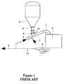
- Figures 1 and 2 show a schematic diagram of a prior art mixing system.
- solid materials are delivered to the mixer 10 directly from a surge can 8 via a flow control valve 6 and are carried into the mixing tub 5 with the mix water.
- the water is delivered via a first water supply 1, and optionally via a second water supply 7 when the amount of water can not be efficiently delivered via the first supply 1 for pressure and flow rate problems.
- the contents of the mixing tub 5 are recirculated with a pump 4, generally a centrifugal pump, through a recirculation pipe 11 to the mixer 10 via a recirculation input 2.
- An output 3 is provided for slurry to be pumped into the well.
- solid materials are delivered to the mixer 10 from a silo via a direct feeding 18 controlled by a flow control valve 16 and are carried into the mixing tub 5 with the mix water.
- the other parts of the mixing system of Figure 2 are similar to those of the mixing system of Figure 1.
- problems occur in efficiency of the mixing process. Problems occur when mixing a solid component and a liquid component, the obtained slurry contains a surplus of gas which impacts on the performance of the mixing process.
- the solid component first to ensure a rapid mixing and secondly to be easily carried and introduced in the mixer, is at the state of granular or powder with natural interstitial voids containing air.
- the solid component can also be fluidized with air to make the solid component more fluid, especially when used with a silo. All this entrapped air will become a serious problem when the liquid and solid components will be mixed. Entrapped air upsets centrifugal pump by decreasing its performance and therefore performance of all the mixing system.
- the present invention seeks to provide a mixing system which avoids the cited problems.
- the invention provides a system for mixing a liquid material and a solid material, said system comprising: (i) a base unit, wherein flows the liquid material and the solid material; (ii) a liquid material supply; (iii) a solid material supply; (iv) a liquid/solid mixing output; (v) an injection means connected to the liquid material supply and to the solid material supply and injecting said liquid material and said solid material in the base unit; (vi) an extraction means extracting from the base unit surplus of gas coming from the mixing of the liquid material and the solid material.
- the mixing system further comprises an extraction means connected to the liquid/solid mixing output and extracting a liquid/solid material substantially without gas from the base unit.
- the base unit is a base cyclic unit ensuring recirculation of the liquid material and the solid material through a recirculation input in the injection means.
- the recirculation ensures a better efficiency in the mixing process and avoids wasting not perfectly mixed slurry.
- the system applies to cement slurry, the liquid material being an aqueous solution (water, solid additives, other liquid additives) and the solid material being cement blend.
- the mixing system has to have performances in quality, in cost and in time.
- the proposed mixing system has all these features due to its rapid, compact and efficient characteristics.
- the extraction means is a cyclonic separation unit.
- the cyclonic separation unit ensures an efficient extraction of gas from the slurry rapidly and costless.
- the cyclonic separation unit is further resistant to problems of corrosion due to use of abrasive components or of erosion due to use of solid components in high speed.
- the extraction means can further comprise a gas surplus output, said gas surplus output being connected to surrounding atmosphere. No pressure equalization has to be done, because the gas will automatically go outside in the atmosphere.
- the injection means is an injector with three nozzles coming respectively from the solid material supply, the liquid material supply, and the recirculation input, the first and second nozzles allowing a first mixing before a second mixing with the third nozzle.
- the solid material is coming substantially perpendicularly to the liquid material, allowing a first mixing.
- the recirculation input is positioned parallel to the liquid material supply and below, so that the slurry coming from the recirculation input is mixed with the liquid material and the solid material after the first mixing. This configuration is suitable to ensure mixing in a cost and time efficient way.
- This injection means is further resistant to problems of corrosion due to use of abrasive components or of erosion due to use of solid components in high speed.
- the system further comprises a control means controlling the solid material supply; said control means being located at a distance sufficiently great from the injection means to remain substantially dry.
- the distance is sufficiently great to avoid splash from the mixer.
- the distance is preferably from some centimeters, preferably more than 5 centimeters, preferably more than 10 centimeters, preferably more than 20 centimeters depending on the diameter of the opening from the solid material supply to the mixer.
- a ratio distance on diameter is preferably greater than 2, preferably greater than 5, preferably greater than 10. Said distance sufficiently great is ensured with a tube, preferably transparent and/or flexible and/or sufficiently vacuum resistant, which is located between the control means and the injection means.
- the tube further can comprise a pressure valve located between the control means and the injection means.
- the pressure valve or vacuum breaker ensures that the mixer is not depressurized when the flow control valve is closed and that the pressure inside the tube remains substantially the same.
- the tube is also empty of solid material thanks to the pressure valve.
- the control means is preferably a knife gate which ensures a constant and repeatable flow rate of the solid material.
- a method for mixing a liquid material and a solid material, said method comprising the steps of: (i) mixing the liquid material and the solid material to form a liquid/solid slurry; (ii) extracting from said liquid/solid slurry surplus of gas coming from the mixing of the liquid material and the solid material; and (iii) extracting from said liquid/solid slurry a liquid/solid material substantially without gas.
- the method can further comprise a recirculation step, where the liquid/solid slurry not extracted in step (iii) is re-injected in the liquid/solid slurry of step (i).
- the recirculation ensures a better efficiency in the mixing process and avoids wasting not perfectly mixed slurry.
- the method can apply to mix cement slurry, the liquid material being an aqueous solution and the solid material being cement blend.
- the step (ii) of extracting surplus of gas can be done with a cyclonic separation unit.
- the cyclonic separation unit ensures an efficient extraction of gas from the slurry rapidly and costless.
- the cyclonic separation unit is further resistant to problems of corrosion due to use of abrasive components or of erosion due to use of solid components in high speed.
- Figure 4 is a schematic diagram of the mixing system according to the invention.
- the major improvement in the proposed mixing system is to eliminate the problem of gas surplus in the mixing process by removing totally or almost totally the gas present in the liquid/solid slurry; whereas the prior art solutions always deal with improving the mixing process by minimizing the gas surplus effect without removing this effect anyway.
- the mixing system comprises a base unit 22' wherein the liquid material and the solid material can be mixed; a liquid material supply 21; a solid material supply 200; an injection means 20 connected to the liquid material supply and to the solid material supply and injecting the liquid material and the solid material in the base unit; an extraction means 24 extracting from the base unit surplus of gas coming from the mixing of the liquid material and the solid material; and an extraction means 204 connected to a liquid/solid mixing output 23 and extracting a solid/liquid material substantially without gas from the base unit.
- the mixing system contains a recirculation loop and the base unit is a base cyclic unit 22 ensuring recirculation in the injection means 20 through a recirculation input 27.
- the recirculation ensures a continuous mixing of the slurry and therefore a better mixing efficiency.
- the recirculation is done thanks to a pump present on the base cyclic unit 22.
- the pump is located between the extraction means 24 and the extraction means 204; the pump can be a centrifugal pump.
- the mixing system can be used for any type of mixing where a liquid component and a solid component comprising intrinsic gas or entrapped air due to its geometry or its composition have to be used.
- the mixing system applies when the solid component is at the state of granular or powder with natural interstitial voids containing air.
- the mixing system applies also when the solid component contains artificial injected air (when fluidized for example to ensure transportation).
- the mixing system applies also when the liquid component and the solid component are chemically reactive or when liquid component and solid component react chemically and produce a gas surplus.
- FIG. 5 is a schematic diagram of a mixing system with a surge can 28.
- the solid materials are delivered to the mixer 20 directly from the surge can 28 via a flow control valve 26.
- the cement is delivered to the surge can from a cement supply 200.
- the mixing fluid is delivered to the mixer from a mixing fluid supply 21.
- the solid materials are carried into the mixing tub 5 with the mixing fluid after have passed in a cyclonic separation unit 24.
- the cyclonic separation unit 24 separates the liquid/solid slurry content from the gas surplus.
- the gas surplus content is extracted from the slurry and ejected to the surrounding atmosphere via a gas surplus output 25.
- the contents of the mixing tub 5 are recirculated with a pump 4 through a recirculation pipe 22 to the mixer 20 via a recirculation input 27.
- the pump 4 is preferably a centrifugal pump.
- An output 23 is provided for slurry to be pumped into the well.
- the extraction means 24 is preferably a cyclonic separation unit.
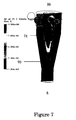
- Figure 7 is a schematic view of the principle of the separation unit.
- the cyclonic separation unit 24 separates the liquid/solid slurry content from the gas surplus and is preferably of the type hydrocyclonic.
- the hydro cyclone 70 installed on the top of the mixing tub 5 separates air from liquid/solid slurry.
- the gas surplus output 25 is an exhaust pipe 71 in communication with the atmosphere. The exhaust pipe releases air in the atmosphere.
- the efficiency of the mixing system has a direct impact on the slurry quality (because with less air), on the mixing time (because with less air, the pump functions efficiently and rapidly).
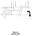
- the mixer of prior art contains a recirculation input nozzle 2 and a surrounding annular nozzle for the water supply 1 which supply respectively the liquid/solid slurry and the liquid component following an axis 2'.
- the solid component is delivered approximately perpendicularly to the axis 2'. Because the liquid component supply is annular, all the liquid component can not be mixed directly at this stage with the solid component.
- the annular supply does not allow a full flow. Effectively, the flow rate and the pressure being the maximum allowed for the liquid component supply 1, a part of the liquid component has to be added upstream via a second liquid supply 7 in the mixing tub 5.
- the mix between liquid and solid components occurs later and therefore the mixing efficiency is consequently reduced.
- the injection means 20 is an injector with three nozzles or a tee mixing bowl. To the mixer 20, three connection inputs or nozzles are coming, respectively: the cement supply (via the tube 29), the mixing fluid supply 21 and the recirculation input 27.
- the system is realized so that cement and mixing fluid are firstly mixed together before to be mixed with the recirculation liquid/solid slurry.
- the nozzle of the mixing fluid supply is substantially perpendicular to the nozzle of the cement supply; the nozzle of the recirculation is also substantially perpendicular to the nozzle of the cement supply and is located below the nozzle of the mixing fluid supply so that when the cement blend falls in the mixer, the cement blend is first in contact with mixing fluid and after with liquid/solid slurry.
- the mixing of the three components which are cement, mixing fluid and liquid/solid slurry is efficiently realized thanks to this configuration of the inputs.
- the efficiency of the mixer has a direct impact on the job quality and job performance.
- the dry cement is delivered to the mixer 20 via the flow control valve 26.
- a tube 29 is present, said tube has a length substantially great to deliver correctly the cement and to allow effective mixing in the mixer 20.
- problem of mixer from prior art is that the exit of the flow control valve remains blocked with dry cement or plugged with liquid/solid slurry.
- the tube 29 further comprises a pressure valve or vacuum breaker 30 located close to the flow control valve 26 and the pressure valve being in communication with surrounding atmosphere.
- the pressure valve allows to empty the tube correctly when the flow control valve is closed, avoids depressurization of the mixer when the flow control valve is closed and ensures a substantially constant pressure inside the tube. For example, when the flow control valve is open with a certain flow rate, the pressure valve is closed and the dry cement falls in the mixer 20. When the flow control valve is closed, the pressure inside the tube is not sufficient, the valve opens and the remaining cement present in the tube 29 falls in the mixer 20 whereas the tube is filled with air. The tube remains clean and no dry cement or liquid/solid slurry blocked the tube and furthermore, the tube remains dry because no depressurization of the mixer has occurred and no condensation has appeared on the surfaces of the tube.
- the flow control valve is a knife gate or slide gate.
- the knife gate allows having a better regulation of the flow of dry cement blend when in powder. Effectively, the cement blend rate is constant, repeatable and independent of other parameters during the mixing process for a given opening of the knife gate. So, the knife gate has a constant and repeatable behavior.
- the tube is preferably transparent to allow control when the cement falls in the mixer and flexible to ensure easy removing. This new configuration of the flow control valve enhances the mixing efficiency. The efficiency of the mixer has a direct impact on the job quality and job performance (because the tube is not often blocked).
- the extraction means 204 is preferably an output line taken in the recirculation pipe 2.
- the output line can be optionally added of a pump, a flow meter.
- the output line delivers the cement slurry for operation in the well (not shown).
- the mixing system can further comprise other devices not shown.
- control of the slurry mixture can be achieved by controlling the density in the mixing tub with a densitometer.
- the densitometer is typically a non-radioactive device such as a Coriolis meter.
- a device for measuring the amount of liquid material or liquid/solid slurry can be added as a flow meter, a level sensor or a load sensor.
- Other pumps can be added to the mixing system to ensure transportation of liquid material or liquid/solid mixture.
- Other valves or flow control units can also be added to the mixing system.
- the mixing system can be easily automated. Effectively, because the proposed mixing system solved problems of prior art systems regarding air and cement blocking in the mixer or close to the flow control valve; the mixing process is simplify and independent, unavoidable and especially unpredictable events will no more happen. It has been noted that the knife gate has a constant and repeatable behavior. Therefore, a control device can be implemented to monitor the input of the flow rate of the solid material and the liquid material depending on the output of the flow rate of the liquid/solid slurry extracted. Alternatively, other parameters can be utilized for the monitoring as the liquid/solid slurry for recirculation, the gas surplus extracted, and the flow rate in the recirculation pipe depending on the pump 4.
- the cement silo can further be replaced by several silos, each silo communicating with the control valve 26 when several solid components have to be mixed together.
- the liquid supply can be replaced by several liquid supplies when several liquid components have to be mixed together.
- mixing systems can be mounted in series. For example, when two solid components with a liquid component have to be mixed, two mixing system are mounted in series, each silo containing one of the solid components.
- FIG. 6 is a schematic diagram of a mixing system with a direct feeding 38 or cement silo.
- the solid materials are delivered to the mixer 20 directly from a cement supply 200 via a flow control valve 26.
- the mixing fluid is delivered to the mixer from a mixing fluid supply 21.
- the solid materials are carried into the mixing tub 5 with the mixing fluid after have passed in a cyclonic separation unit 24.
- the cyclonic separation unit 24 separates the liquid/solid slurry content from the gas surplus.
- the gas surplus content is extracted from the slurry and ejected to the surrounding atmosphere via a gas surplus output 25.
- the contents of the mixing tub 5 are recirculated with a pump 4 through a recirculation pipe 22 to the mixer 20 via a recirculation input 27.
- the pump 4 is preferably a centrifugal pump.
- An output 23 is provided for slurry to be pumped into the well.
- the present invention also disclosed a method for mixing slurry made of a liquid material and a solid material.
- the operation in the mixing process are first, to mix the liquid material and the solid material to form a liquid/solid slurry; secondly, to extract from the liquid/solid slurry obtained surplus of gas coming from the mixing of the liquid material and the solid material; and finally, to extract from the liquid/solid slurry a liquid/solid material substantially without gas.
- the mixing process can further comprise a recirculation step where the non extracted slurry of last step is re-injected at the beginning of the mix of the liquid/solid slurry. The recirculation ensures a continuous mixing of the slurry and therefore a better mixing efficiency.
- the method is directly applied to the mixing system described above.
Landscapes
- Chemical & Material Sciences (AREA)
- Chemical Kinetics & Catalysis (AREA)
- Engineering & Computer Science (AREA)
- Mechanical Engineering (AREA)
- Mining & Mineral Resources (AREA)
- Geology (AREA)
- Life Sciences & Earth Sciences (AREA)
- Dispersion Chemistry (AREA)
- Structural Engineering (AREA)
- Physics & Mathematics (AREA)
- Toxicology (AREA)
- Environmental & Geological Engineering (AREA)
- Fluid Mechanics (AREA)
- General Health & Medical Sciences (AREA)
- Health & Medical Sciences (AREA)
- General Life Sciences & Earth Sciences (AREA)
- Geochemistry & Mineralogy (AREA)
- Preparation Of Clay, And Manufacture Of Mixtures Containing Clay Or Cement (AREA)
- Accessories For Mixers (AREA)
- Physical Or Chemical Processes And Apparatus (AREA)
Abstract
Description
- The present invention broadly relates to mixing system. More particularly the invention relates to an apparatus and related method for mixing a liquid material and a solid material to obtain a slurry in a cost, time and performance efficiency way. The apparatus removes any gas or air surplus in the solid/liquid mixing and improves the mixing process. In particular the invention provides a system for the continuous mixing of cements or other fluids used in the drilling, completion or stimulation of boreholes such as oil or gas wells.
- When a well such as an oil or gas well has been drilled, it is often desired to isolate the various producing zones from each other or from the well itself in order to stabilize the well or prevent fluid communication between the zones or shut off unwanted fluid production such as water. This isolation is typically achieved by installing a tubular casing in the well and filling the annulus between the outside of the casing and the wall of the well (the formation) with cement. The cement is usually placed in the annulus by pumping slurry of the cement down the casing such that it exits at the bottom of the well and passes back up the outside of the casing to fill the annulus. While it is possible to mix the cement as a batch prior to pumping into the well, it has become desirable to effect continuous and optimized mixing of the cement slurry at the surface just prior to pumping into the well. This has been found to provide better control of cement properties and more efficient use of materials.
- The cement slurries used in such operations comprise a mixture of dry and liquid materials. The liquid phase is typically water and so is readily available and cheap. The solid materials define the slurry and cement properties when added to the water and mixed. Figures 1 and 2 show a schematic diagram of a prior art mixing system. In Figure 1, solid materials are delivered to the
mixer 10 directly from a surge can 8 via aflow control valve 6 and are carried into themixing tub 5 with the mix water. The water is delivered via afirst water supply 1, and optionally via asecond water supply 7 when the amount of water can not be efficiently delivered via thefirst supply 1 for pressure and flow rate problems. The contents of themixing tub 5 are recirculated with apump 4, generally a centrifugal pump, through arecirculation pipe 11 to themixer 10 via arecirculation input 2. Anoutput 3 is provided for slurry to be pumped into the well. In Figure 2, solid materials are delivered to themixer 10 from a silo via adirect feeding 18 controlled by aflow control valve 16 and are carried into themixing tub 5 with the mix water. The other parts of the mixing system of Figure 2 are similar to those of the mixing system of Figure 1. - Actually, when using mixing systems of prior art, problems occur in efficiency of the mixing process. Problems occur when mixing a solid component and a liquid component, the obtained slurry contains a surplus of gas which impacts on the performance of the mixing process. The solid component, first to ensure a rapid mixing and secondly to be easily carried and introduced in the mixer, is at the state of granular or powder with natural interstitial voids containing air. The solid component can also be fluidized with air to make the solid component more fluid, especially when used with a silo. All this entrapped air will become a serious problem when the liquid and solid components will be mixed. Entrapped air upsets centrifugal pump by decreasing its performance and therefore performance of all the mixing system.
- The present invention seeks to provide a mixing system which avoids the cited problems.
- The invention provides a system for mixing a liquid material and a solid material, said system comprising: (i) a base unit, wherein flows the liquid material and the solid material; (ii) a liquid material supply; (iii) a solid material supply; (iv) a liquid/solid mixing output; (v) an injection means connected to the liquid material supply and to the solid material supply and injecting said liquid material and said solid material in the base unit; (vi) an extraction means extracting from the base unit surplus of gas coming from the mixing of the liquid material and the solid material.
- Preferably, the mixing system further comprises an extraction means connected to the liquid/solid mixing output and extracting a liquid/solid material substantially without gas from the base unit.
- Preferably, the base unit is a base cyclic unit ensuring recirculation of the liquid material and the solid material through a recirculation input in the injection means. The recirculation ensures a better efficiency in the mixing process and avoids wasting not perfectly mixed slurry.
- In a preferred embodiment, the system applies to cement slurry, the liquid material being an aqueous solution (water, solid additives, other liquid additives) and the solid material being cement blend. To mix cement slurry, the mixing system has to have performances in quality, in cost and in time. The proposed mixing system has all these features due to its rapid, compact and efficient characteristics.
- Preferably, the extraction means is a cyclonic separation unit. The cyclonic separation unit ensures an efficient extraction of gas from the slurry rapidly and costless. The cyclonic separation unit is further resistant to problems of corrosion due to use of abrasive components or of erosion due to use of solid components in high speed. The extraction means can further comprise a gas surplus output, said gas surplus output being connected to surrounding atmosphere. No pressure equalization has to be done, because the gas will automatically go outside in the atmosphere.
- Preferably, the injection means is an injector with three nozzles coming respectively from the solid material supply, the liquid material supply, and the recirculation input, the first and second nozzles allowing a first mixing before a second mixing with the third nozzle. Preferably, the solid material is coming substantially perpendicularly to the liquid material, allowing a first mixing. The recirculation input is positioned parallel to the liquid material supply and below, so that the slurry coming from the recirculation input is mixed with the liquid material and the solid material after the first mixing. This configuration is suitable to ensure mixing in a cost and time efficient way. This injection means is further resistant to problems of corrosion due to use of abrasive components or of erosion due to use of solid components in high speed.
- In a preferred embodiment, the system further comprises a control means controlling the solid material supply; said control means being located at a distance sufficiently great from the injection means to remain substantially dry. Preferably, the distance is sufficiently great to avoid splash from the mixer. The distance is preferably from some centimeters, preferably more than 5 centimeters, preferably more than 10 centimeters, preferably more than 20 centimeters depending on the diameter of the opening from the solid material supply to the mixer. A ratio distance on diameter is preferably greater than 2, preferably greater than 5, preferably greater than 10. Said distance sufficiently great is ensured with a tube, preferably transparent and/or flexible and/or sufficiently vacuum resistant, which is located between the control means and the injection means. The tube further can comprise a pressure valve located between the control means and the injection means. The pressure valve or vacuum breaker ensures that the mixer is not depressurized when the flow control valve is closed and that the pressure inside the tube remains substantially the same. The tube is also empty of solid material thanks to the pressure valve. The control means is preferably a knife gate which ensures a constant and repeatable flow rate of the solid material.
- In another aspect of the invention, a method is described for mixing a liquid material and a solid material, said method comprising the steps of: (i) mixing the liquid material and the solid material to form a liquid/solid slurry; (ii) extracting from said liquid/solid slurry surplus of gas coming from the mixing of the liquid material and the solid material; and (iii) extracting from said liquid/solid slurry a liquid/solid material substantially without gas.
- The method can further comprise a recirculation step, where the liquid/solid slurry not extracted in step (iii) is re-injected in the liquid/solid slurry of step (i). The recirculation ensures a better efficiency in the mixing process and avoids wasting not perfectly mixed slurry.
- The method can apply to mix cement slurry, the liquid material being an aqueous solution and the solid material being cement blend.
- The step (ii) of extracting surplus of gas can be done with a cyclonic separation unit. The cyclonic separation unit ensures an efficient extraction of gas from the slurry rapidly and costless. The cyclonic separation unit is further resistant to problems of corrosion due to use of abrasive components or of erosion due to use of solid components in high speed.
- Further embodiments of the present invention can be understood with the appended drawings:
- Figure 1 shows a schematic diagram of a mixing system with a surge can of solid material supply from Prior Art.
- Figure 2 shows a schematic diagram of a mixing system with a silo for solid material supply from Prior Art.
- Figure 3 shows a mixer from Prior Art.
- Figure 4 shows a schematic diagram of the mixing system according to the invention.
- Figure 5 shows a schematic diagram of a mixing system with a surge can of solid material supply.
- Figure 6 shows a schematic diagram of a mixing system with a silo for solid material supply.
- Figure 7 shows a schematic view of the principle of the separation gas/liquid/solid.
- Figure 4 is a schematic diagram of the mixing system according to the invention. The major improvement in the proposed mixing system is to eliminate the problem of gas surplus in the mixing process by removing totally or almost totally the gas present in the liquid/solid slurry; whereas the prior art solutions always deal with improving the mixing process by minimizing the gas surplus effect without removing this effect anyway. The mixing system comprises a base unit 22' wherein the liquid material and the solid material can be mixed; a
liquid material supply 21; asolid material supply 200; an injection means 20 connected to the liquid material supply and to the solid material supply and injecting the liquid material and the solid material in the base unit; an extraction means 24 extracting from the base unit surplus of gas coming from the mixing of the liquid material and the solid material; and an extraction means 204 connected to a liquid/solid mixing output 23 and extracting a solid/liquid material substantially without gas from the base unit. In a preferred embodiment the mixing system contains a recirculation loop and the base unit is a basecyclic unit 22 ensuring recirculation in the injection means 20 through arecirculation input 27. The recirculation ensures a continuous mixing of the slurry and therefore a better mixing efficiency. The recirculation is done thanks to a pump present on the basecyclic unit 22. Preferably, the pump is located between the extraction means 24 and the extraction means 204; the pump can be a centrifugal pump. - The mixing system can be used for any type of mixing where a liquid component and a solid component comprising intrinsic gas or entrapped air due to its geometry or its composition have to be used. Especially, the mixing system applies when the solid component is at the state of granular or powder with natural interstitial voids containing air. The mixing system applies also when the solid component contains artificial injected air (when fluidized for example to ensure transportation). The mixing system applies also when the liquid component and the solid component are chemically reactive or when liquid component and solid component react chemically and produce a gas surplus.
- In the preferred embodiment the solid component is dry cement blend and the liquid component is a mixing fluid, which comprises water and other additives or aqueous solutions. Figure 5 is a schematic diagram of a mixing system with a surge can 28. The solid materials are delivered to the
mixer 20 directly from the surge can 28 via aflow control valve 26. The cement is delivered to the surge can from acement supply 200. And the mixing fluid is delivered to the mixer from a mixingfluid supply 21. The solid materials are carried into the mixingtub 5 with the mixing fluid after have passed in acyclonic separation unit 24. Thecyclonic separation unit 24 separates the liquid/solid slurry content from the gas surplus. The gas surplus content is extracted from the slurry and ejected to the surrounding atmosphere via agas surplus output 25. The contents of the mixingtub 5 are recirculated with apump 4 through arecirculation pipe 22 to themixer 20 via arecirculation input 27. Thepump 4 is preferably a centrifugal pump. Anoutput 23 is provided for slurry to be pumped into the well. - The extraction means 24 is preferably a cyclonic separation unit. Figure 7 is a schematic view of the principle of the separation unit. The
cyclonic separation unit 24 separates the liquid/solid slurry content from the gas surplus and is preferably of the type hydrocyclonic. Using centrifugation principle, thehydro cyclone 70 installed on the top of the mixingtub 5 separates air from liquid/solid slurry. Thegas surplus output 25 is anexhaust pipe 71 in communication with the atmosphere. The exhaust pipe releases air in the atmosphere. - A test has been realized with and without hydro cyclone before the mixing tub. When the exhaust pipe is closed (which corresponds to a mixing system without hydro cyclone) the total volume of the slurry present in the mixing system increases and we can evaluate that 7% of the volume of the slurry is air. Therefore, when the hydro cyclone functions at least 7% of the gas surplus or entrapped air present in the slurry is extracted. Furthermore, it has been shown that for prior art systems, 2% of air present in the slurry decreases the centrifugal pump efficiency of 10% i.e. the efficiency of the mixing system, and 4% of air present in the slurry decreases the centrifugal pump efficiency of 43%. A decreasing of 7% of air present in the slurry increases consequently in a large way the efficiency of the mixing system. The efficiency of the mixing system has a direct impact on the slurry quality (because with less air), on the mixing time (because with less air, the pump functions efficiently and rapidly).
- Additionally, in mixing systems Figures 1 and 2 of Prior Art, another problem occurs directly in the
mixer 10. The mixer of prior art is disclosed in Figure 3. The mixer contains arecirculation input nozzle 2 and a surrounding annular nozzle for thewater supply 1 which supply respectively the liquid/solid slurry and the liquid component following an axis 2'. The solid component is delivered approximately perpendicularly to the axis 2'. Because the liquid component supply is annular, all the liquid component can not be mixed directly at this stage with the solid component. The annular supply does not allow a full flow. Effectively, the flow rate and the pressure being the maximum allowed for theliquid component supply 1, a part of the liquid component has to be added upstream via a secondliquid supply 7 in the mixingtub 5. The mix between liquid and solid components occurs later and therefore the mixing efficiency is consequently reduced. Furthermore, a part of the liquid component mixed first with the solid component and another part of the liquid component mixed first with the liquid/solid slurry. This light delay causes inefficiency in the mixing process. - Also, in the preferred embodiment of the invention, the injection means 20 is an injector with three nozzles or a tee mixing bowl. To the
mixer 20, three connection inputs or nozzles are coming, respectively: the cement supply (via the tube 29), the mixingfluid supply 21 and therecirculation input 27. The system is realized so that cement and mixing fluid are firstly mixed together before to be mixed with the recirculation liquid/solid slurry. The nozzle of the mixing fluid supply is substantially perpendicular to the nozzle of the cement supply; the nozzle of the recirculation is also substantially perpendicular to the nozzle of the cement supply and is located below the nozzle of the mixing fluid supply so that when the cement blend falls in the mixer, the cement blend is first in contact with mixing fluid and after with liquid/solid slurry. There is no need as in prior art systems to add a second mixing fluid supply, because all the mixing fluid can be delivered efficiently at this location. The mixing of the three components which are cement, mixing fluid and liquid/solid slurry is efficiently realized thanks to this configuration of the inputs. The efficiency of the mixer has a direct impact on the job quality and job performance. - Additionally, in mixing systems Figures 1 and 2 of Prior Art, another problem occurs just before the
mixer 10 at the position of thevalve 6 for the cement silo orvalve 16 for the surge can. Due to architecture problem and position of the valve close to the liquid supply, the mixer is often blocked with dry solid or plugged with liquid/solid slurry. When the surrounding region (tube 9 and mixer 10) of the valve is completely blocked and can not ensure an efficient mixing process, the mixing system has to be dismantled to clean and remove the solid content blocking the apparatus. Mostly, this operation is costly, time consuming and especially not ecological. Effectively, when thetube 9 and themixer 10 have to be cleaned from blocked "non-green" cement on a field location, generally the cement is emptied out of the mixer into the earth surface soiling the ground water. Furthermore, because dry solid or liquid/solid slurry blocked the exit of the valve, the predefined flow rate of the valve is changed. This change in the flow rate of the valve remains uncontrollable and independent of the solid component delivery. - Also, in the preferred embodiment of the invention, the dry cement is delivered to the
mixer 20 via theflow control valve 26. Between the flow control valve and the mixer atube 29 is present, said tube has a length substantially great to deliver correctly the cement and to allow effective mixing in themixer 20. As said previously, problem of mixer from prior art is that the exit of the flow control valve remains blocked with dry cement or plugged with liquid/solid slurry. By increasing the distance between the flow control valve and the mixer, the probability to have a blocked valve decreases. The distance is sufficiently great to avoid splash coming from the mixer and so that the flow control valve remains substantially dry. Thetube 29 further comprises a pressure valve orvacuum breaker 30 located close to theflow control valve 26 and the pressure valve being in communication with surrounding atmosphere. The pressure valve allows to empty the tube correctly when the flow control valve is closed, avoids depressurization of the mixer when the flow control valve is closed and ensures a substantially constant pressure inside the tube. For example, when the flow control valve is open with a certain flow rate, the pressure valve is closed and the dry cement falls in themixer 20. When the flow control valve is closed, the pressure inside the tube is not sufficient, the valve opens and the remaining cement present in thetube 29 falls in themixer 20 whereas the tube is filled with air. The tube remains clean and no dry cement or liquid/solid slurry blocked the tube and furthermore, the tube remains dry because no depressurization of the mixer has occurred and no condensation has appeared on the surfaces of the tube. The skilled in the art will appreciate that thanks to thecyclonic separation unit 24, the air present in the tube is not a problem and will be extracted from the slurry. In a preferred embodiment the flow control valve is a knife gate or slide gate. The knife gate allows having a better regulation of the flow of dry cement blend when in powder. Effectively, the cement blend rate is constant, repeatable and independent of other parameters during the mixing process for a given opening of the knife gate. So, the knife gate has a constant and repeatable behavior. The tube is preferably transparent to allow control when the cement falls in the mixer and flexible to ensure easy removing. This new configuration of the flow control valve enhances the mixing efficiency. The efficiency of the mixer has a direct impact on the job quality and job performance (because the tube is not often blocked). - The extraction means 204 is preferably an output line taken in the
recirculation pipe 2. The output line can be optionally added of a pump, a flow meter. The output line delivers the cement slurry for operation in the well (not shown). - The mixing system can further comprise other devices not shown. For example, control of the slurry mixture can be achieved by controlling the density in the mixing tub with a densitometer. The densitometer is typically a non-radioactive device such as a Coriolis meter. A device for measuring the amount of liquid material or liquid/solid slurry can be added as a flow meter, a level sensor or a load sensor. Other pumps can be added to the mixing system to ensure transportation of liquid material or liquid/solid mixture. Other valves or flow control units can also be added to the mixing system.
- In a further aspect of the invention, the mixing system can be easily automated. Effectively, because the proposed mixing system solved problems of prior art systems regarding air and cement blocking in the mixer or close to the flow control valve; the mixing process is simplify and independent, unavoidable and especially unpredictable events will no more happen. It has been noted that the knife gate has a constant and repeatable behavior. Therefore, a control device can be implemented to monitor the input of the flow rate of the solid material and the liquid material depending on the output of the flow rate of the liquid/solid slurry extracted. Alternatively, other parameters can be utilized for the monitoring as the liquid/solid slurry for recirculation, the gas surplus extracted, and the flow rate in the recirculation pipe depending on the
pump 4. - The cement silo can further be replaced by several silos, each silo communicating with the
control valve 26 when several solid components have to be mixed together. In the same way, the liquid supply can be replaced by several liquid supplies when several liquid components have to be mixed together. Or alternatively, mixing systems can be mounted in series. For example, when two solid components with a liquid component have to be mixed, two mixing system are mounted in series, each silo containing one of the solid components. - Figure 6 is a schematic diagram of a mixing system with a
direct feeding 38 or cement silo. The solid materials are delivered to themixer 20 directly from acement supply 200 via aflow control valve 26. And the mixing fluid is delivered to the mixer from a mixingfluid supply 21. The solid materials are carried into the mixingtub 5 with the mixing fluid after have passed in acyclonic separation unit 24. Thecyclonic separation unit 24 separates the liquid/solid slurry content from the gas surplus. The gas surplus content is extracted from the slurry and ejected to the surrounding atmosphere via agas surplus output 25. The contents of the mixingtub 5 are recirculated with apump 4 through arecirculation pipe 22 to themixer 20 via arecirculation input 27. Thepump 4 is preferably a centrifugal pump. Anoutput 23 is provided for slurry to be pumped into the well. The embodiments already disclosed for the mixing system with a surge can apply also for this mixing system with a direct feeding. - The present invention also disclosed a method for mixing slurry made of a liquid material and a solid material. The operation in the mixing process are first, to mix the liquid material and the solid material to form a liquid/solid slurry; secondly, to extract from the liquid/solid slurry obtained surplus of gas coming from the mixing of the liquid material and the solid material; and finally, to extract from the liquid/solid slurry a liquid/solid material substantially without gas. In a preferred embodiment, the mixing process can further comprise a recirculation step where the non extracted slurry of last step is re-injected at the beginning of the mix of the liquid/solid slurry. The recirculation ensures a continuous mixing of the slurry and therefore a better mixing efficiency. The method is directly applied to the mixing system described above.
Claims (16)
- A system for mixing a liquid material and a solid material, said system comprising:i) a base unit (22'), wherein flows the liquid material and the solid material;ii) a liquid material supply (21);iii) a solid material supply (200);iv) a liquid/solid mixing output (23); andv) an injection means (20) connected to the liquid material supply and to the solid material supply and injecting said liquid material and said solid material in the base unit;
characterized in that, the system further comprising:vi) an extraction means (24) extracting from the base unit surplus of gas coming from the mixing of the liquid material and the solid material. - The system of claim 1, further comprising an extraction means (204) connected to the liquid/solid mixing output and extracting a liquid/solid material substantially without gas from the base unit.
- The system of claim 1 or 2, wherein the base unit is a base cyclic unit (22) ensuring recirculation of the liquid material and the solid material through a recirculation input (27) in the injection means (20).
- The system according to any one of claims 1 to 3, wherein the mixing applied to a cement slurry, the liquid material being an aqueous solution and the solid material being cement blend.
- The system according to any one of claims 1 to 4, wherein the extraction means is a cyclonic separation unit.
- The system according to any one of claims 1 to 5, wherein the extraction means further comprises a gas surplus output (25), said gas surplus output being connected to surrounding atmosphere.
- The system according to any one of claims 3 to 6, wherein the injection means is an injector with three nozzles coming respectively from the solid material supply (200), the liquid material supply (21), and the recirculation input (27), the first and second nozzles allowing a first mixing before a second mixing with the third nozzle.
- The system according to any one of claims 3 to 7, further comprising a control means (26) controlling the solid material supply, said control means being located at a distance sufficiently great from the injection means to remain substantially dry.
- The system of claim 8, wherein a transparent tub (29) is located between the control means and the injection means.
- The system of claim 8 or 9, further comprising a pressure valve (30) located between the control means and the injection means.
- The system according to any one of claims 3 to 10, wherein the control means is a knife gate.
- The system according to any one of claims 1 to 11, wherein the mixing system is an automated system with a control device, said control device controlling the solid material supply.
- A method for mixing a liquid material and a solid material, said method comprising the steps of:i) mixing the liquid material and the solid material to form a liquid/solid slurry;ii) extracting from said liquid/solid slurry surplus of gas coming from the mixing of the liquid material and the solid material; andiii) extracting from said liquid/solid slurry a liquid/solid material substantially without gas.
- The method of claim 13, further comprising the step of re-injecting the liquid/solid slurry not extracted in step iii) in the liquid/solid slurry of step i).
- The method of claim 13 or 14, wherein the method applied to mix a cement slurry, the liquid material being an aqueous solution and the solid material being dry cement.
- The method according to any one of claims 13 to 15, wherein the step ii) of extracting surplus of gas is done with a cyclonic separation unit.
Priority Applications (8)
| Application Number | Priority Date | Filing Date | Title |
|---|---|---|---|
| EP05291577A EP1745840A1 (en) | 2005-07-22 | 2005-07-22 | Apparatus and method for mixing a liquid material and a flowable powdery material to obtain a slurry |
| CN2006800344309A CN101309744B (en) | 2005-07-22 | 2006-06-29 | Method and apparatus to optimize the mixing process |
| BRPI0613630-3A BRPI0613630A2 (en) | 2005-07-22 | 2006-06-29 | system for mixing a liquid material and a solid material, and method for mixing a liquid material and a solid material |
| CA2615556A CA2615556C (en) | 2005-07-22 | 2006-06-29 | Method and apparatus to optimize the mixing process |
| US11/996,087 US20080212397A1 (en) | 2005-07-22 | 2006-06-29 | Method and Apparatus to Optimize the Mixing Process |
| PCT/EP2006/006302 WO2007009567A2 (en) | 2005-07-22 | 2006-06-29 | Apparatus and method for mixing a liquid material and a flowable powdery material to obtain a slurry |
| NO20080306A NO20080306L (en) | 2005-07-22 | 2008-01-17 | Method and apparatus for optimizing the mixing process |
| US13/084,051 US20110235460A1 (en) | 2005-07-22 | 2011-04-11 | Method and apparatus to optimize the mixing process |
Applications Claiming Priority (1)
| Application Number | Priority Date | Filing Date | Title |
|---|---|---|---|
| EP05291577A EP1745840A1 (en) | 2005-07-22 | 2005-07-22 | Apparatus and method for mixing a liquid material and a flowable powdery material to obtain a slurry |
Publications (1)
| Publication Number | Publication Date |
|---|---|
| EP1745840A1 true EP1745840A1 (en) | 2007-01-24 |
Family
ID=35385534
Family Applications (1)
| Application Number | Title | Priority Date | Filing Date |
|---|---|---|---|
| EP05291577A Ceased EP1745840A1 (en) | 2005-07-22 | 2005-07-22 | Apparatus and method for mixing a liquid material and a flowable powdery material to obtain a slurry |
Country Status (7)
| Country | Link |
|---|---|
| US (1) | US20080212397A1 (en) |
| EP (1) | EP1745840A1 (en) |
| CN (1) | CN101309744B (en) |
| BR (1) | BRPI0613630A2 (en) |
| CA (1) | CA2615556C (en) |
| NO (1) | NO20080306L (en) |
| WO (1) | WO2007009567A2 (en) |
Cited By (6)
| Publication number | Priority date | Publication date | Assignee | Title |
|---|---|---|---|---|
| CN102755854A (en) * | 2011-04-28 | 2012-10-31 | 宝山钢铁股份有限公司 | Stable control method and stable control device for sand feeding system |
| WO2014039063A1 (en) | 2012-09-07 | 2014-03-13 | Dow Global Technologies Llc | Toughening masterblends |
| CN103752204A (en) * | 2014-01-26 | 2014-04-30 | 中国地质大学(武汉) | Dispersing treatment device for multi-component washing fluid |
| US9010989B2 (en) | 2008-04-14 | 2015-04-21 | Schlumberger Technology Corporation | Container system |
| CN106390791A (en) * | 2016-08-19 | 2017-02-15 | 深圳市尚水智能设备有限公司 | Novel process and novel equipment for preparing paste for lithium batteries |
| CN112334221A (en) * | 2018-07-05 | 2021-02-05 | 日本斯频德制造株式会社 | Slurry production apparatus and slurry production method |
Families Citing this family (10)
| Publication number | Priority date | Publication date | Assignee | Title |
|---|---|---|---|---|
| US20110235460A1 (en) * | 2005-07-22 | 2011-09-29 | Schlumberger Technology Corporation | Method and apparatus to optimize the mixing process |
| US20080298163A1 (en) * | 2007-06-01 | 2008-12-04 | Jean-Louis Pessin | Vibration Assisted Mixer |
| CN102641689A (en) * | 2011-02-18 | 2012-08-22 | 五冶集团上海有限公司 | Simple slurrying device |
| CN103104240B (en) * | 2013-01-15 | 2016-08-03 | 中国石油大学(华东) | A kind of downhole oil-water separation device of band plural parallel stage hydrocyclone |
| US10961832B2 (en) | 2013-07-23 | 2021-03-30 | Schlumberger Technology Corporation | Methods of treatment of a subterranean formation with polymeric structures formed in situ |
| CN104047558B (en) * | 2014-06-13 | 2017-01-04 | 中国石油集团西部钻探工程有限公司 | Liquid-gas separator exhaust line automatic draining device |
| US10589238B2 (en) | 2016-03-14 | 2020-03-17 | Schlumberger Technology Corporation | Mixing system for cement and fluids |
| CN106738357A (en) * | 2016-12-28 | 2017-05-31 | 佛山市研得机电有限公司 | A kind of moveable efficient mini concrete mixing plant |
| US11845046B2 (en) | 2019-10-08 | 2023-12-19 | Industrial Dielectrics, Inc. | Mixing system and method of using the same |
| CN114516690B (en) * | 2022-02-24 | 2023-05-23 | 武汉地质勘察基础工程有限公司 | Waste mud treatment system and method |
Citations (8)
| Publication number | Priority date | Publication date | Assignee | Title |
|---|---|---|---|---|
| US4007921A (en) | 1976-01-19 | 1977-02-15 | The Dow Chemical Company | Apparatus for mixing dry particles with a liquid |
| EP0616839A1 (en) * | 1993-03-20 | 1994-09-28 | Philipp Holzmann AG | Method and device for continuously mixing of several solid and/or liquid components especially for making concrete |
| US5571281A (en) * | 1996-02-09 | 1996-11-05 | Allen; Thomas E. | Automatic cement mixing and density simulator and control system and equipment for oil well cementing |
| DE19537874A1 (en) * | 1995-10-11 | 1997-04-17 | Dyckerhoff Ag | Process and device for the production of fine cement / fine binder suspensions |
| EP1025896A1 (en) * | 1995-05-12 | 2000-08-09 | Halliburton Energy Services, Inc. | Apparatus and method for mixing |
| US20020093875A1 (en) * | 2000-11-29 | 2002-07-18 | Joel Rondeau | Fluid mixing system |
| US20030081493A1 (en) * | 2001-11-01 | 2003-05-01 | Allen Thomas E. | Cement mixing system for oil well cementing |
| US6568842B1 (en) * | 2000-06-13 | 2003-05-27 | United States Lime And Minerals, Inc. | High capacity mobile lime slaker |
Family Cites Families (32)
| Publication number | Priority date | Publication date | Assignee | Title |
|---|---|---|---|---|
| US1996209A (en) * | 1933-11-13 | 1935-04-02 | Koehring Co | Vibrator |
| US2176893A (en) * | 1939-04-25 | 1939-10-24 | George B Engleby | Vibrator for skips of concrete mixing machines |
| BE473052A (en) * | 1945-07-23 | |||
| DE962308C (en) * | 1953-07-28 | 1957-04-18 | Bayer Ag | Feeding device arranged in the filling funnel of processing machines |
| US2746733A (en) * | 1953-12-09 | 1956-05-22 | Ira L Edgerton | Asphalt pavement construction |
| US2795403A (en) * | 1954-10-28 | 1957-06-11 | William H Mead | Slurry mixing method and apparatus |
| US3091369A (en) * | 1960-07-19 | 1963-05-28 | Sackett & Sons Co A J | Weighing and mixing hopper |
| DE1222428B (en) * | 1965-05-06 | 1966-08-04 | Kalle Ag | Feeding device for screw machines |
| US4210175A (en) * | 1976-03-22 | 1980-07-01 | Daniels Raymond R | Chemical injection assembly |
| US4074687A (en) * | 1976-06-30 | 1978-02-21 | Joyce John E | Method of and apparatus for use in generating liquid concentration gradients hydrostatically |
| US4155249A (en) * | 1977-05-16 | 1979-05-22 | Scott Forrest G | Thermal-aerosol generators |
| US4334786A (en) * | 1978-02-08 | 1982-06-15 | Saint Gobain Industries | Process and mechanism for evolutive pulp flow regulation |
| US4226542A (en) * | 1979-04-05 | 1980-10-07 | Weigh-Tech, Inc. | Cement slurry reclamation system and method |
| US4291503A (en) * | 1979-09-05 | 1981-09-29 | Yasunaga Higashi | Workpiece treating barrel |
| US4390284A (en) * | 1980-01-25 | 1983-06-28 | Neptune Microfloc, Inc. | Method and apparatus for wetting powder |
| US4629903A (en) * | 1984-10-09 | 1986-12-16 | Mobil Oil Corporation | Method of monitoring a catalyst feed and apparatus for implementing the method |
| US4854714A (en) * | 1988-05-27 | 1989-08-08 | Halliburton Company | Blender vehicle apparatus |
| US4922463A (en) * | 1988-08-22 | 1990-05-01 | Del Zotto Manufacturing Co. | Portable volumetric concrete mixer/silo |
| US4997284A (en) * | 1988-12-16 | 1991-03-05 | E-Con Mega Mix | Concrete and mortar distribution process and apparatus |
| US5114239A (en) * | 1989-09-21 | 1992-05-19 | Halliburton Company | Mixing apparatus and method |
| US5009508A (en) * | 1990-03-26 | 1991-04-23 | Wojdylo Henry K | Apparatus for mixing concrete |
| JPH07115895B2 (en) * | 1990-07-19 | 1995-12-13 | 株式会社ネオテック | Recycling method and equipment for washing residues such as ready-mixed concrete |
| US5344619A (en) * | 1993-03-10 | 1994-09-06 | Betz Paperchem, Inc. | Apparatus for dissolving dry polymer |
| US5516009A (en) * | 1994-03-04 | 1996-05-14 | Tecnetics Industries, Inc. | Stirrer for a hopper |
| US5544951A (en) * | 1994-09-30 | 1996-08-13 | Semi-Bulk Systems, Inc. | Mixing module for mixing a fluent particulate material with a working fluid |
| WO1998043726A1 (en) * | 1997-03-27 | 1998-10-08 | Pei Technology Ltd. | Apparatus and method for mixing cementitious materials |
| WO2004011131A2 (en) * | 2002-07-25 | 2004-02-05 | University Of Florida | Flexible screw feeder/mixer for precision dosing and feeding of particulate systems |
| EP1508417A1 (en) * | 2003-07-24 | 2005-02-23 | Services Petroliers Schlumberger | Blending system |
| DE10356245B4 (en) * | 2003-12-02 | 2007-01-25 | Alphakat Gmbh | Process for the production of diesel oil from hydrocarbon-containing residues and an apparatus for carrying out this process |
| US8303159B2 (en) * | 2008-09-05 | 2012-11-06 | United States Gypsum Company | Efficient wet starch preparation system for gypsum board production |
| US20100157720A1 (en) * | 2008-12-19 | 2010-06-24 | Michael Woodmansee | Vibration Enhanced Mixing Process |
| US7824457B2 (en) * | 2009-03-02 | 2010-11-02 | Witter Robert M | Portable cyclonic dust collector |
-
2005
- 2005-07-22 EP EP05291577A patent/EP1745840A1/en not_active Ceased
-
2006
- 2006-06-29 CA CA2615556A patent/CA2615556C/en not_active Expired - Fee Related
- 2006-06-29 US US11/996,087 patent/US20080212397A1/en not_active Abandoned
- 2006-06-29 BR BRPI0613630-3A patent/BRPI0613630A2/en not_active IP Right Cessation
- 2006-06-29 WO PCT/EP2006/006302 patent/WO2007009567A2/en not_active Ceased
- 2006-06-29 CN CN2006800344309A patent/CN101309744B/en not_active Expired - Fee Related
-
2008
- 2008-01-17 NO NO20080306A patent/NO20080306L/en not_active Application Discontinuation
Patent Citations (9)
| Publication number | Priority date | Publication date | Assignee | Title |
|---|---|---|---|---|
| US4007921A (en) | 1976-01-19 | 1977-02-15 | The Dow Chemical Company | Apparatus for mixing dry particles with a liquid |
| EP0616839A1 (en) * | 1993-03-20 | 1994-09-28 | Philipp Holzmann AG | Method and device for continuously mixing of several solid and/or liquid components especially for making concrete |
| EP1025896A1 (en) * | 1995-05-12 | 2000-08-09 | Halliburton Energy Services, Inc. | Apparatus and method for mixing |
| DE19537874A1 (en) * | 1995-10-11 | 1997-04-17 | Dyckerhoff Ag | Process and device for the production of fine cement / fine binder suspensions |
| US5571281A (en) * | 1996-02-09 | 1996-11-05 | Allen; Thomas E. | Automatic cement mixing and density simulator and control system and equipment for oil well cementing |
| US6568842B1 (en) * | 2000-06-13 | 2003-05-27 | United States Lime And Minerals, Inc. | High capacity mobile lime slaker |
| US20020093875A1 (en) * | 2000-11-29 | 2002-07-18 | Joel Rondeau | Fluid mixing system |
| US20030072208A1 (en) * | 2000-11-29 | 2003-04-17 | Joel Rondeau | Automated cement mixing system |
| US20030081493A1 (en) * | 2001-11-01 | 2003-05-01 | Allen Thomas E. | Cement mixing system for oil well cementing |
Cited By (8)
| Publication number | Priority date | Publication date | Assignee | Title |
|---|---|---|---|---|
| US9010989B2 (en) | 2008-04-14 | 2015-04-21 | Schlumberger Technology Corporation | Container system |
| CN102755854A (en) * | 2011-04-28 | 2012-10-31 | 宝山钢铁股份有限公司 | Stable control method and stable control device for sand feeding system |
| CN102755854B (en) * | 2011-04-28 | 2014-12-03 | 宝山钢铁股份有限公司 | Stable control method and stable control device for sand feeding system |
| WO2014039063A1 (en) | 2012-09-07 | 2014-03-13 | Dow Global Technologies Llc | Toughening masterblends |
| CN103752204A (en) * | 2014-01-26 | 2014-04-30 | 中国地质大学(武汉) | Dispersing treatment device for multi-component washing fluid |
| CN103752204B (en) * | 2014-01-26 | 2016-02-03 | 中国地质大学(武汉) | A kind of dispersion treatment device for multicomponent flushing liquor |
| CN106390791A (en) * | 2016-08-19 | 2017-02-15 | 深圳市尚水智能设备有限公司 | Novel process and novel equipment for preparing paste for lithium batteries |
| CN112334221A (en) * | 2018-07-05 | 2021-02-05 | 日本斯频德制造株式会社 | Slurry production apparatus and slurry production method |
Also Published As
| Publication number | Publication date |
|---|---|
| CN101309744B (en) | 2012-12-05 |
| CA2615556A1 (en) | 2007-01-25 |
| WO2007009567A3 (en) | 2007-04-19 |
| WO2007009567A2 (en) | 2007-01-25 |
| CA2615556C (en) | 2010-09-28 |
| CN101309744A (en) | 2008-11-19 |
| US20080212397A1 (en) | 2008-09-04 |
| BRPI0613630A2 (en) | 2011-01-18 |
| NO20080306L (en) | 2008-02-13 |
Similar Documents
| Publication | Publication Date | Title |
|---|---|---|
| CA2615556C (en) | Method and apparatus to optimize the mixing process | |
| US20200215502A1 (en) | Mixing System for Cement and Fluids | |
| CN101600849B (en) | High Density Slurry | |
| US6357906B1 (en) | Method and device for mixing a bulk material with a fluid | |
| US20190106972A1 (en) | Apparatus and method of preparing and delivering a fluid mixture using direct proppant injection | |
| CN109931043A (en) | A kind of online filling apparatus and method of slippery water powder drag reducer | |
| RU2652591C2 (en) | Control system and apparatus for delivery of non-aqueous fracturing fluid | |
| CN104271316A (en) | An abrasive jet system | |
| RU2079353C1 (en) | Method and device for mixing solid and liquid matters | |
| CA2305015C (en) | Mixing method and apparatus | |
| CN104053496A (en) | Mixing methods and systems for fluids | |
| CN204073898U (en) | A kind of horizontal powder of lacquer putty for use on mixer | |
| CN110886590B (en) | Rapid grouting device for coal body partition grouting | |
| US4170420A (en) | Fluid mixing system | |
| US20170122064A1 (en) | Mixing System For Cementing Applications | |
| CN112780222B (en) | Device and method for automatically controlling sectional filling of plugging material | |
| US20110235460A1 (en) | Method and apparatus to optimize the mixing process | |
| RU2206706C2 (en) | Method of density control of grounting mortars and flushing fluids and device for method embodiment | |
| CN104741028A (en) | High molecular polymer automatic adding device | |
| CN107701161A (en) | A kind of mixture pumping system and its device | |
| RU2150381C1 (en) | Mixing installation for preparation of solutions | |
| CN115387821A (en) | Device and method for continuously pouring aggregate in grading manner through drilling | |
| RU2179928C1 (en) | Mixing apparatus for preparing solutions | |
| JP4321715B2 (en) | Ground improvement method | |
| CN209596951U (en) | One kind quickly mixing new device for oil field equipment siccative |
Legal Events
| Date | Code | Title | Description |
|---|---|---|---|
| PUAI | Public reference made under article 153(3) epc to a published international application that has entered the european phase |
Free format text: ORIGINAL CODE: 0009012 |
|
| AK | Designated contracting states |
Kind code of ref document: A1 Designated state(s): AT BE BG CH CY CZ DE DK EE ES FI FR GB GR HU IE IS IT LI LT LU LV MC NL PL PT RO SE SI SK TR |
|
| AX | Request for extension of the european patent |
Extension state: AL BA HR MK YU |
|
| 17P | Request for examination filed |
Effective date: 20070704 |
|
| AKX | Designation fees paid |
Designated state(s): AT BE BG CH CY CZ DE DK EE ES FI FR GB GR HU IE IS IT LI LT LU LV MC NL PL PT RO SE SI SK TR |
|
| 17Q | First examination report despatched |
Effective date: 20090202 |
|
| STAA | Information on the status of an ep patent application or granted ep patent |
Free format text: STATUS: THE APPLICATION HAS BEEN REFUSED |
|
| 18R | Application refused |
Effective date: 20101213 |