EP1745764A2 - Appareil d'impaction d'un implant - Google Patents
Appareil d'impaction d'un implant Download PDFInfo
- Publication number
- EP1745764A2 EP1745764A2 EP06123846A EP06123846A EP1745764A2 EP 1745764 A2 EP1745764 A2 EP 1745764A2 EP 06123846 A EP06123846 A EP 06123846A EP 06123846 A EP06123846 A EP 06123846A EP 1745764 A2 EP1745764 A2 EP 1745764A2
- Authority
- EP
- European Patent Office
- Prior art keywords
- bone
- femoral
- joint
- implant
- knee
- Prior art date
- Legal status (The legal status is an assumption and is not a legal conclusion. Google has not performed a legal analysis and makes no representation as to the accuracy of the status listed.)
- Granted
Links
Images


Classifications
-
- A—HUMAN NECESSITIES
- A61—MEDICAL OR VETERINARY SCIENCE; HYGIENE
- A61B—DIAGNOSIS; SURGERY; IDENTIFICATION
- A61B17/00—Surgical instruments, devices or methods, e.g. tourniquets
- A61B17/16—Bone cutting, breaking or removal means other than saws, e.g. Osteoclasts; Drills or chisels for bones; Trepans
- A61B17/1613—Component parts
- A61B17/1628—Motors; Power supplies
-
- A—HUMAN NECESSITIES
- A61—MEDICAL OR VETERINARY SCIENCE; HYGIENE
- A61B—DIAGNOSIS; SURGERY; IDENTIFICATION
- A61B17/00—Surgical instruments, devices or methods, e.g. tourniquets
- A61B17/16—Bone cutting, breaking or removal means other than saws, e.g. Osteoclasts; Drills or chisels for bones; Trepans
- A61B17/1613—Component parts
- A61B17/1631—Special drive shafts, e.g. flexible shafts
-
- A—HUMAN NECESSITIES
- A61—MEDICAL OR VETERINARY SCIENCE; HYGIENE
- A61B—DIAGNOSIS; SURGERY; IDENTIFICATION
- A61B17/00—Surgical instruments, devices or methods, e.g. tourniquets
- A61B17/16—Bone cutting, breaking or removal means other than saws, e.g. Osteoclasts; Drills or chisels for bones; Trepans
- A61B17/1662—Bone cutting, breaking or removal means other than saws, e.g. Osteoclasts; Drills or chisels for bones; Trepans for particular parts of the body
- A61B17/1664—Bone cutting, breaking or removal means other than saws, e.g. Osteoclasts; Drills or chisels for bones; Trepans for particular parts of the body for the hip
- A61B17/1666—Bone cutting, breaking or removal means other than saws, e.g. Osteoclasts; Drills or chisels for bones; Trepans for particular parts of the body for the hip for the acetabulum
-
- A—HUMAN NECESSITIES
- A61—MEDICAL OR VETERINARY SCIENCE; HYGIENE
- A61B—DIAGNOSIS; SURGERY; IDENTIFICATION
- A61B17/00—Surgical instruments, devices or methods, e.g. tourniquets
- A61B17/16—Bone cutting, breaking or removal means other than saws, e.g. Osteoclasts; Drills or chisels for bones; Trepans
- A61B17/1662—Bone cutting, breaking or removal means other than saws, e.g. Osteoclasts; Drills or chisels for bones; Trepans for particular parts of the body
- A61B17/1675—Bone cutting, breaking or removal means other than saws, e.g. Osteoclasts; Drills or chisels for bones; Trepans for particular parts of the body for the knee
-
- A—HUMAN NECESSITIES
- A61—MEDICAL OR VETERINARY SCIENCE; HYGIENE
- A61B—DIAGNOSIS; SURGERY; IDENTIFICATION
- A61B17/00—Surgical instruments, devices or methods, e.g. tourniquets
- A61B17/32—Surgical cutting instruments
- A61B17/320016—Endoscopic cutting instruments, e.g. arthroscopes, resectoscopes
- A61B17/32002—Endoscopic cutting instruments, e.g. arthroscopes, resectoscopes with continuously rotating, oscillating or reciprocating cutting instruments
-
- A—HUMAN NECESSITIES
- A61—MEDICAL OR VETERINARY SCIENCE; HYGIENE
- A61F—FILTERS IMPLANTABLE INTO BLOOD VESSELS; PROSTHESES; DEVICES PROVIDING PATENCY TO, OR PREVENTING COLLAPSING OF, TUBULAR STRUCTURES OF THE BODY, e.g. STENTS; ORTHOPAEDIC, NURSING OR CONTRACEPTIVE DEVICES; FOMENTATION; TREATMENT OR PROTECTION OF EYES OR EARS; BANDAGES, DRESSINGS OR ABSORBENT PADS; FIRST-AID KITS
- A61F2/00—Filters implantable into blood vessels; Prostheses, i.e. artificial substitutes or replacements for parts of the body; Appliances for connecting them with the body; Devices providing patency to, or preventing collapsing of, tubular structures of the body, e.g. stents
- A61F2/02—Prostheses implantable into the body
- A61F2/30—Joints
- A61F2/30721—Accessories
- A61F2/30724—Spacers for centering an implant in a bone cavity, e.g. in a cement-receiving cavity
-
- A—HUMAN NECESSITIES
- A61—MEDICAL OR VETERINARY SCIENCE; HYGIENE
- A61F—FILTERS IMPLANTABLE INTO BLOOD VESSELS; PROSTHESES; DEVICES PROVIDING PATENCY TO, OR PREVENTING COLLAPSING OF, TUBULAR STRUCTURES OF THE BODY, e.g. STENTS; ORTHOPAEDIC, NURSING OR CONTRACEPTIVE DEVICES; FOMENTATION; TREATMENT OR PROTECTION OF EYES OR EARS; BANDAGES, DRESSINGS OR ABSORBENT PADS; FIRST-AID KITS
- A61F2/00—Filters implantable into blood vessels; Prostheses, i.e. artificial substitutes or replacements for parts of the body; Appliances for connecting them with the body; Devices providing patency to, or preventing collapsing of, tubular structures of the body, e.g. stents
- A61F2/02—Prostheses implantable into the body
- A61F2/30—Joints
- A61F2/38—Joints for elbows or knees
-
- A—HUMAN NECESSITIES
- A61—MEDICAL OR VETERINARY SCIENCE; HYGIENE
- A61F—FILTERS IMPLANTABLE INTO BLOOD VESSELS; PROSTHESES; DEVICES PROVIDING PATENCY TO, OR PREVENTING COLLAPSING OF, TUBULAR STRUCTURES OF THE BODY, e.g. STENTS; ORTHOPAEDIC, NURSING OR CONTRACEPTIVE DEVICES; FOMENTATION; TREATMENT OR PROTECTION OF EYES OR EARS; BANDAGES, DRESSINGS OR ABSORBENT PADS; FIRST-AID KITS
- A61F2/00—Filters implantable into blood vessels; Prostheses, i.e. artificial substitutes or replacements for parts of the body; Appliances for connecting them with the body; Devices providing patency to, or preventing collapsing of, tubular structures of the body, e.g. stents
- A61F2/02—Prostheses implantable into the body
- A61F2/30—Joints
- A61F2/46—Special tools or methods for implanting or extracting artificial joints, accessories, bone grafts or substitutes, or particular adaptations therefor
- A61F2/4603—Special tools or methods for implanting or extracting artificial joints, accessories, bone grafts or substitutes, or particular adaptations therefor for insertion or extraction of endoprosthetic joints or of accessories thereof
- A61F2/4609—Special tools or methods for implanting or extracting artificial joints, accessories, bone grafts or substitutes, or particular adaptations therefor for insertion or extraction of endoprosthetic joints or of accessories thereof of acetabular cups
-
- A—HUMAN NECESSITIES
- A61—MEDICAL OR VETERINARY SCIENCE; HYGIENE
- A61F—FILTERS IMPLANTABLE INTO BLOOD VESSELS; PROSTHESES; DEVICES PROVIDING PATENCY TO, OR PREVENTING COLLAPSING OF, TUBULAR STRUCTURES OF THE BODY, e.g. STENTS; ORTHOPAEDIC, NURSING OR CONTRACEPTIVE DEVICES; FOMENTATION; TREATMENT OR PROTECTION OF EYES OR EARS; BANDAGES, DRESSINGS OR ABSORBENT PADS; FIRST-AID KITS
- A61F2/00—Filters implantable into blood vessels; Prostheses, i.e. artificial substitutes or replacements for parts of the body; Appliances for connecting them with the body; Devices providing patency to, or preventing collapsing of, tubular structures of the body, e.g. stents
- A61F2/02—Prostheses implantable into the body
- A61F2/30—Joints
- A61F2/46—Special tools or methods for implanting or extracting artificial joints, accessories, bone grafts or substitutes, or particular adaptations therefor
- A61F2/4684—Trial or dummy prostheses
-
- A—HUMAN NECESSITIES
- A61—MEDICAL OR VETERINARY SCIENCE; HYGIENE
- A61B—DIAGNOSIS; SURGERY; IDENTIFICATION
- A61B17/00—Surgical instruments, devices or methods, e.g. tourniquets
- A61B17/00234—Surgical instruments, devices or methods, e.g. tourniquets for minimally invasive surgery
-
- A—HUMAN NECESSITIES
- A61—MEDICAL OR VETERINARY SCIENCE; HYGIENE
- A61B—DIAGNOSIS; SURGERY; IDENTIFICATION
- A61B17/00—Surgical instruments, devices or methods, e.g. tourniquets
- A61B17/02—Surgical instruments, devices or methods, e.g. tourniquets for holding wounds open; Tractors
- A61B17/0206—Surgical instruments, devices or methods, e.g. tourniquets for holding wounds open; Tractors with antagonistic arms as supports for retractor elements
-
- A—HUMAN NECESSITIES
- A61—MEDICAL OR VETERINARY SCIENCE; HYGIENE
- A61B—DIAGNOSIS; SURGERY; IDENTIFICATION
- A61B17/00—Surgical instruments, devices or methods, e.g. tourniquets
- A61B17/02—Surgical instruments, devices or methods, e.g. tourniquets for holding wounds open; Tractors
- A61B17/025—Joint distractors
-
- A—HUMAN NECESSITIES
- A61—MEDICAL OR VETERINARY SCIENCE; HYGIENE
- A61B—DIAGNOSIS; SURGERY; IDENTIFICATION
- A61B17/00—Surgical instruments, devices or methods, e.g. tourniquets
- A61B2017/00367—Details of actuation of instruments, e.g. relations between pushing buttons, or the like, and activation of the tool, working tip, or the like
- A61B2017/00398—Details of actuation of instruments, e.g. relations between pushing buttons, or the like, and activation of the tool, working tip, or the like using powered actuators, e.g. stepper motors, solenoids
-
- A—HUMAN NECESSITIES
- A61—MEDICAL OR VETERINARY SCIENCE; HYGIENE
- A61B—DIAGNOSIS; SURGERY; IDENTIFICATION
- A61B17/00—Surgical instruments, devices or methods, e.g. tourniquets
- A61B2017/00535—Surgical instruments, devices or methods, e.g. tourniquets pneumatically or hydraulically operated
- A61B2017/00539—Surgical instruments, devices or methods, e.g. tourniquets pneumatically or hydraulically operated hydraulically
-
- A—HUMAN NECESSITIES
- A61—MEDICAL OR VETERINARY SCIENCE; HYGIENE
- A61B—DIAGNOSIS; SURGERY; IDENTIFICATION
- A61B17/00—Surgical instruments, devices or methods, e.g. tourniquets
- A61B2017/00535—Surgical instruments, devices or methods, e.g. tourniquets pneumatically or hydraulically operated
- A61B2017/00557—Surgical instruments, devices or methods, e.g. tourniquets pneumatically or hydraulically operated inflatable
-
- A—HUMAN NECESSITIES
- A61—MEDICAL OR VETERINARY SCIENCE; HYGIENE
- A61B—DIAGNOSIS; SURGERY; IDENTIFICATION
- A61B17/00—Surgical instruments, devices or methods, e.g. tourniquets
- A61B17/02—Surgical instruments, devices or methods, e.g. tourniquets for holding wounds open; Tractors
- A61B17/025—Joint distractors
- A61B2017/0268—Joint distractors for the knee
-
- A—HUMAN NECESSITIES
- A61—MEDICAL OR VETERINARY SCIENCE; HYGIENE
- A61B—DIAGNOSIS; SURGERY; IDENTIFICATION
- A61B17/00—Surgical instruments, devices or methods, e.g. tourniquets
- A61B17/02—Surgical instruments, devices or methods, e.g. tourniquets for holding wounds open; Tractors
- A61B17/025—Joint distractors
- A61B2017/0275—Joint distractors for the hip
-
- A—HUMAN NECESSITIES
- A61—MEDICAL OR VETERINARY SCIENCE; HYGIENE
- A61B—DIAGNOSIS; SURGERY; IDENTIFICATION
- A61B17/00—Surgical instruments, devices or methods, e.g. tourniquets
- A61B17/16—Bone cutting, breaking or removal means other than saws, e.g. Osteoclasts; Drills or chisels for bones; Trepans
- A61B2017/1602—Mills
-
- A—HUMAN NECESSITIES
- A61—MEDICAL OR VETERINARY SCIENCE; HYGIENE
- A61F—FILTERS IMPLANTABLE INTO BLOOD VESSELS; PROSTHESES; DEVICES PROVIDING PATENCY TO, OR PREVENTING COLLAPSING OF, TUBULAR STRUCTURES OF THE BODY, e.g. STENTS; ORTHOPAEDIC, NURSING OR CONTRACEPTIVE DEVICES; FOMENTATION; TREATMENT OR PROTECTION OF EYES OR EARS; BANDAGES, DRESSINGS OR ABSORBENT PADS; FIRST-AID KITS
- A61F2/00—Filters implantable into blood vessels; Prostheses, i.e. artificial substitutes or replacements for parts of the body; Appliances for connecting them with the body; Devices providing patency to, or preventing collapsing of, tubular structures of the body, e.g. stents
- A61F2/02—Prostheses implantable into the body
- A61F2/30—Joints
- A61F2/30767—Special external or bone-contacting surface, e.g. coating for improving bone ingrowth
-
- A—HUMAN NECESSITIES
- A61—MEDICAL OR VETERINARY SCIENCE; HYGIENE
- A61F—FILTERS IMPLANTABLE INTO BLOOD VESSELS; PROSTHESES; DEVICES PROVIDING PATENCY TO, OR PREVENTING COLLAPSING OF, TUBULAR STRUCTURES OF THE BODY, e.g. STENTS; ORTHOPAEDIC, NURSING OR CONTRACEPTIVE DEVICES; FOMENTATION; TREATMENT OR PROTECTION OF EYES OR EARS; BANDAGES, DRESSINGS OR ABSORBENT PADS; FIRST-AID KITS
- A61F2/00—Filters implantable into blood vessels; Prostheses, i.e. artificial substitutes or replacements for parts of the body; Appliances for connecting them with the body; Devices providing patency to, or preventing collapsing of, tubular structures of the body, e.g. stents
- A61F2/02—Prostheses implantable into the body
- A61F2/30—Joints
- A61F2/3094—Designing or manufacturing processes
- A61F2/30942—Designing or manufacturing processes for designing or making customized prostheses, e.g. using templates, CT or NMR scans, finite-element analysis or CAD-CAM techniques
-
- A—HUMAN NECESSITIES
- A61—MEDICAL OR VETERINARY SCIENCE; HYGIENE
- A61F—FILTERS IMPLANTABLE INTO BLOOD VESSELS; PROSTHESES; DEVICES PROVIDING PATENCY TO, OR PREVENTING COLLAPSING OF, TUBULAR STRUCTURES OF THE BODY, e.g. STENTS; ORTHOPAEDIC, NURSING OR CONTRACEPTIVE DEVICES; FOMENTATION; TREATMENT OR PROTECTION OF EYES OR EARS; BANDAGES, DRESSINGS OR ABSORBENT PADS; FIRST-AID KITS
- A61F2/00—Filters implantable into blood vessels; Prostheses, i.e. artificial substitutes or replacements for parts of the body; Appliances for connecting them with the body; Devices providing patency to, or preventing collapsing of, tubular structures of the body, e.g. stents
- A61F2/02—Prostheses implantable into the body
- A61F2/30—Joints
- A61F2/32—Joints for the hip
- A61F2/34—Acetabular cups
-
- A—HUMAN NECESSITIES
- A61—MEDICAL OR VETERINARY SCIENCE; HYGIENE
- A61F—FILTERS IMPLANTABLE INTO BLOOD VESSELS; PROSTHESES; DEVICES PROVIDING PATENCY TO, OR PREVENTING COLLAPSING OF, TUBULAR STRUCTURES OF THE BODY, e.g. STENTS; ORTHOPAEDIC, NURSING OR CONTRACEPTIVE DEVICES; FOMENTATION; TREATMENT OR PROTECTION OF EYES OR EARS; BANDAGES, DRESSINGS OR ABSORBENT PADS; FIRST-AID KITS
- A61F2/00—Filters implantable into blood vessels; Prostheses, i.e. artificial substitutes or replacements for parts of the body; Appliances for connecting them with the body; Devices providing patency to, or preventing collapsing of, tubular structures of the body, e.g. stents
- A61F2/02—Prostheses implantable into the body
- A61F2/30—Joints
- A61F2/32—Joints for the hip
- A61F2/36—Femoral heads ; Femoral endoprostheses
- A61F2/3662—Femoral shafts
-
- A—HUMAN NECESSITIES
- A61—MEDICAL OR VETERINARY SCIENCE; HYGIENE
- A61F—FILTERS IMPLANTABLE INTO BLOOD VESSELS; PROSTHESES; DEVICES PROVIDING PATENCY TO, OR PREVENTING COLLAPSING OF, TUBULAR STRUCTURES OF THE BODY, e.g. STENTS; ORTHOPAEDIC, NURSING OR CONTRACEPTIVE DEVICES; FOMENTATION; TREATMENT OR PROTECTION OF EYES OR EARS; BANDAGES, DRESSINGS OR ABSORBENT PADS; FIRST-AID KITS
- A61F2/00—Filters implantable into blood vessels; Prostheses, i.e. artificial substitutes or replacements for parts of the body; Appliances for connecting them with the body; Devices providing patency to, or preventing collapsing of, tubular structures of the body, e.g. stents
- A61F2/02—Prostheses implantable into the body
- A61F2/30—Joints
- A61F2/38—Joints for elbows or knees
- A61F2/3859—Femoral components
-
- A—HUMAN NECESSITIES
- A61—MEDICAL OR VETERINARY SCIENCE; HYGIENE
- A61F—FILTERS IMPLANTABLE INTO BLOOD VESSELS; PROSTHESES; DEVICES PROVIDING PATENCY TO, OR PREVENTING COLLAPSING OF, TUBULAR STRUCTURES OF THE BODY, e.g. STENTS; ORTHOPAEDIC, NURSING OR CONTRACEPTIVE DEVICES; FOMENTATION; TREATMENT OR PROTECTION OF EYES OR EARS; BANDAGES, DRESSINGS OR ABSORBENT PADS; FIRST-AID KITS
- A61F2/00—Filters implantable into blood vessels; Prostheses, i.e. artificial substitutes or replacements for parts of the body; Appliances for connecting them with the body; Devices providing patency to, or preventing collapsing of, tubular structures of the body, e.g. stents
- A61F2/02—Prostheses implantable into the body
- A61F2/30—Joints
- A61F2/38—Joints for elbows or knees
- A61F2/3872—Meniscus for implantation between the natural bone surfaces
-
- A—HUMAN NECESSITIES
- A61—MEDICAL OR VETERINARY SCIENCE; HYGIENE
- A61F—FILTERS IMPLANTABLE INTO BLOOD VESSELS; PROSTHESES; DEVICES PROVIDING PATENCY TO, OR PREVENTING COLLAPSING OF, TUBULAR STRUCTURES OF THE BODY, e.g. STENTS; ORTHOPAEDIC, NURSING OR CONTRACEPTIVE DEVICES; FOMENTATION; TREATMENT OR PROTECTION OF EYES OR EARS; BANDAGES, DRESSINGS OR ABSORBENT PADS; FIRST-AID KITS
- A61F2/00—Filters implantable into blood vessels; Prostheses, i.e. artificial substitutes or replacements for parts of the body; Appliances for connecting them with the body; Devices providing patency to, or preventing collapsing of, tubular structures of the body, e.g. stents
- A61F2/02—Prostheses implantable into the body
- A61F2/30—Joints
- A61F2/38—Joints for elbows or knees
- A61F2/3877—Patellae or trochleae
-
- A—HUMAN NECESSITIES
- A61—MEDICAL OR VETERINARY SCIENCE; HYGIENE
- A61F—FILTERS IMPLANTABLE INTO BLOOD VESSELS; PROSTHESES; DEVICES PROVIDING PATENCY TO, OR PREVENTING COLLAPSING OF, TUBULAR STRUCTURES OF THE BODY, e.g. STENTS; ORTHOPAEDIC, NURSING OR CONTRACEPTIVE DEVICES; FOMENTATION; TREATMENT OR PROTECTION OF EYES OR EARS; BANDAGES, DRESSINGS OR ABSORBENT PADS; FIRST-AID KITS
- A61F2/00—Filters implantable into blood vessels; Prostheses, i.e. artificial substitutes or replacements for parts of the body; Appliances for connecting them with the body; Devices providing patency to, or preventing collapsing of, tubular structures of the body, e.g. stents
- A61F2/02—Prostheses implantable into the body
- A61F2/30—Joints
- A61F2/38—Joints for elbows or knees
- A61F2/389—Tibial components
-
- A—HUMAN NECESSITIES
- A61—MEDICAL OR VETERINARY SCIENCE; HYGIENE
- A61F—FILTERS IMPLANTABLE INTO BLOOD VESSELS; PROSTHESES; DEVICES PROVIDING PATENCY TO, OR PREVENTING COLLAPSING OF, TUBULAR STRUCTURES OF THE BODY, e.g. STENTS; ORTHOPAEDIC, NURSING OR CONTRACEPTIVE DEVICES; FOMENTATION; TREATMENT OR PROTECTION OF EYES OR EARS; BANDAGES, DRESSINGS OR ABSORBENT PADS; FIRST-AID KITS
- A61F2/00—Filters implantable into blood vessels; Prostheses, i.e. artificial substitutes or replacements for parts of the body; Appliances for connecting them with the body; Devices providing patency to, or preventing collapsing of, tubular structures of the body, e.g. stents
- A61F2/02—Prostheses implantable into the body
- A61F2/30—Joints
- A61F2/46—Special tools or methods for implanting or extracting artificial joints, accessories, bone grafts or substitutes, or particular adaptations therefor
- A61F2/4603—Special tools or methods for implanting or extracting artificial joints, accessories, bone grafts or substitutes, or particular adaptations therefor for insertion or extraction of endoprosthetic joints or of accessories thereof
-
- A—HUMAN NECESSITIES
- A61—MEDICAL OR VETERINARY SCIENCE; HYGIENE
- A61F—FILTERS IMPLANTABLE INTO BLOOD VESSELS; PROSTHESES; DEVICES PROVIDING PATENCY TO, OR PREVENTING COLLAPSING OF, TUBULAR STRUCTURES OF THE BODY, e.g. STENTS; ORTHOPAEDIC, NURSING OR CONTRACEPTIVE DEVICES; FOMENTATION; TREATMENT OR PROTECTION OF EYES OR EARS; BANDAGES, DRESSINGS OR ABSORBENT PADS; FIRST-AID KITS
- A61F2/00—Filters implantable into blood vessels; Prostheses, i.e. artificial substitutes or replacements for parts of the body; Appliances for connecting them with the body; Devices providing patency to, or preventing collapsing of, tubular structures of the body, e.g. stents
- A61F2/02—Prostheses implantable into the body
- A61F2/30—Joints
- A61F2002/30001—Additional features of subject-matter classified in A61F2/28, A61F2/30 and subgroups thereof
- A61F2002/30003—Material related properties of the prosthesis or of a coating on the prosthesis
- A61F2002/3006—Properties of materials and coating materials
- A61F2002/30092—Properties of materials and coating materials using shape memory or superelastic materials, e.g. nitinol
-
- A—HUMAN NECESSITIES
- A61—MEDICAL OR VETERINARY SCIENCE; HYGIENE
- A61F—FILTERS IMPLANTABLE INTO BLOOD VESSELS; PROSTHESES; DEVICES PROVIDING PATENCY TO, OR PREVENTING COLLAPSING OF, TUBULAR STRUCTURES OF THE BODY, e.g. STENTS; ORTHOPAEDIC, NURSING OR CONTRACEPTIVE DEVICES; FOMENTATION; TREATMENT OR PROTECTION OF EYES OR EARS; BANDAGES, DRESSINGS OR ABSORBENT PADS; FIRST-AID KITS
- A61F2/00—Filters implantable into blood vessels; Prostheses, i.e. artificial substitutes or replacements for parts of the body; Appliances for connecting them with the body; Devices providing patency to, or preventing collapsing of, tubular structures of the body, e.g. stents
- A61F2/02—Prostheses implantable into the body
- A61F2/30—Joints
- A61F2002/30001—Additional features of subject-matter classified in A61F2/28, A61F2/30 and subgroups thereof
- A61F2002/30316—The prosthesis having different structural features at different locations within the same prosthesis; Connections between prosthetic parts; Special structural features of bone or joint prostheses not otherwise provided for
- A61F2002/30535—Special structural features of bone or joint prostheses not otherwise provided for
- A61F2002/30604—Special structural features of bone or joint prostheses not otherwise provided for modular
- A61F2002/30616—Sets comprising a plurality of prosthetic parts of different sizes or orientations
-
- A—HUMAN NECESSITIES
- A61—MEDICAL OR VETERINARY SCIENCE; HYGIENE
- A61F—FILTERS IMPLANTABLE INTO BLOOD VESSELS; PROSTHESES; DEVICES PROVIDING PATENCY TO, OR PREVENTING COLLAPSING OF, TUBULAR STRUCTURES OF THE BODY, e.g. STENTS; ORTHOPAEDIC, NURSING OR CONTRACEPTIVE DEVICES; FOMENTATION; TREATMENT OR PROTECTION OF EYES OR EARS; BANDAGES, DRESSINGS OR ABSORBENT PADS; FIRST-AID KITS
- A61F2/00—Filters implantable into blood vessels; Prostheses, i.e. artificial substitutes or replacements for parts of the body; Appliances for connecting them with the body; Devices providing patency to, or preventing collapsing of, tubular structures of the body, e.g. stents
- A61F2/02—Prostheses implantable into the body
- A61F2/30—Joints
- A61F2/30767—Special external or bone-contacting surface, e.g. coating for improving bone ingrowth
- A61F2/30771—Special external or bone-contacting surface, e.g. coating for improving bone ingrowth applied in original prostheses, e.g. holes or grooves
- A61F2002/30878—Special external or bone-contacting surface, e.g. coating for improving bone ingrowth applied in original prostheses, e.g. holes or grooves with non-sharp protrusions, for instance contacting the bone for anchoring, e.g. keels, pegs, pins, posts, shanks, stems, struts
- A61F2002/30884—Fins or wings, e.g. longitudinal wings for preventing rotation within the bone cavity
-
- A—HUMAN NECESSITIES
- A61—MEDICAL OR VETERINARY SCIENCE; HYGIENE
- A61F—FILTERS IMPLANTABLE INTO BLOOD VESSELS; PROSTHESES; DEVICES PROVIDING PATENCY TO, OR PREVENTING COLLAPSING OF, TUBULAR STRUCTURES OF THE BODY, e.g. STENTS; ORTHOPAEDIC, NURSING OR CONTRACEPTIVE DEVICES; FOMENTATION; TREATMENT OR PROTECTION OF EYES OR EARS; BANDAGES, DRESSINGS OR ABSORBENT PADS; FIRST-AID KITS
- A61F2/00—Filters implantable into blood vessels; Prostheses, i.e. artificial substitutes or replacements for parts of the body; Appliances for connecting them with the body; Devices providing patency to, or preventing collapsing of, tubular structures of the body, e.g. stents
- A61F2/02—Prostheses implantable into the body
- A61F2/30—Joints
- A61F2/30767—Special external or bone-contacting surface, e.g. coating for improving bone ingrowth
- A61F2/30771—Special external or bone-contacting surface, e.g. coating for improving bone ingrowth applied in original prostheses, e.g. holes or grooves
- A61F2002/30878—Special external or bone-contacting surface, e.g. coating for improving bone ingrowth applied in original prostheses, e.g. holes or grooves with non-sharp protrusions, for instance contacting the bone for anchoring, e.g. keels, pegs, pins, posts, shanks, stems, struts
- A61F2002/30891—Plurality of protrusions
- A61F2002/30894—Plurality of protrusions inclined obliquely with respect to each other
-
- A—HUMAN NECESSITIES
- A61—MEDICAL OR VETERINARY SCIENCE; HYGIENE
- A61F—FILTERS IMPLANTABLE INTO BLOOD VESSELS; PROSTHESES; DEVICES PROVIDING PATENCY TO, OR PREVENTING COLLAPSING OF, TUBULAR STRUCTURES OF THE BODY, e.g. STENTS; ORTHOPAEDIC, NURSING OR CONTRACEPTIVE DEVICES; FOMENTATION; TREATMENT OR PROTECTION OF EYES OR EARS; BANDAGES, DRESSINGS OR ABSORBENT PADS; FIRST-AID KITS
- A61F2/00—Filters implantable into blood vessels; Prostheses, i.e. artificial substitutes or replacements for parts of the body; Appliances for connecting them with the body; Devices providing patency to, or preventing collapsing of, tubular structures of the body, e.g. stents
- A61F2/02—Prostheses implantable into the body
- A61F2/30—Joints
- A61F2/38—Joints for elbows or knees
- A61F2002/3895—Joints for elbows or knees unicompartimental
-
- A—HUMAN NECESSITIES
- A61—MEDICAL OR VETERINARY SCIENCE; HYGIENE
- A61F—FILTERS IMPLANTABLE INTO BLOOD VESSELS; PROSTHESES; DEVICES PROVIDING PATENCY TO, OR PREVENTING COLLAPSING OF, TUBULAR STRUCTURES OF THE BODY, e.g. STENTS; ORTHOPAEDIC, NURSING OR CONTRACEPTIVE DEVICES; FOMENTATION; TREATMENT OR PROTECTION OF EYES OR EARS; BANDAGES, DRESSINGS OR ABSORBENT PADS; FIRST-AID KITS
- A61F2/00—Filters implantable into blood vessels; Prostheses, i.e. artificial substitutes or replacements for parts of the body; Appliances for connecting them with the body; Devices providing patency to, or preventing collapsing of, tubular structures of the body, e.g. stents
- A61F2/02—Prostheses implantable into the body
- A61F2/30—Joints
- A61F2/46—Special tools or methods for implanting or extracting artificial joints, accessories, bone grafts or substitutes, or particular adaptations therefor
- A61F2002/4631—Special tools or methods for implanting or extracting artificial joints, accessories, bone grafts or substitutes, or particular adaptations therefor the prosthesis being specially adapted for being cemented
-
- A—HUMAN NECESSITIES
- A61—MEDICAL OR VETERINARY SCIENCE; HYGIENE
- A61F—FILTERS IMPLANTABLE INTO BLOOD VESSELS; PROSTHESES; DEVICES PROVIDING PATENCY TO, OR PREVENTING COLLAPSING OF, TUBULAR STRUCTURES OF THE BODY, e.g. STENTS; ORTHOPAEDIC, NURSING OR CONTRACEPTIVE DEVICES; FOMENTATION; TREATMENT OR PROTECTION OF EYES OR EARS; BANDAGES, DRESSINGS OR ABSORBENT PADS; FIRST-AID KITS
- A61F2/00—Filters implantable into blood vessels; Prostheses, i.e. artificial substitutes or replacements for parts of the body; Appliances for connecting them with the body; Devices providing patency to, or preventing collapsing of, tubular structures of the body, e.g. stents
- A61F2/02—Prostheses implantable into the body
- A61F2/30—Joints
- A61F2/46—Special tools or methods for implanting or extracting artificial joints, accessories, bone grafts or substitutes, or particular adaptations therefor
- A61F2002/4635—Special tools or methods for implanting or extracting artificial joints, accessories, bone grafts or substitutes, or particular adaptations therefor using minimally invasive surgery
-
- A—HUMAN NECESSITIES
- A61—MEDICAL OR VETERINARY SCIENCE; HYGIENE
- A61F—FILTERS IMPLANTABLE INTO BLOOD VESSELS; PROSTHESES; DEVICES PROVIDING PATENCY TO, OR PREVENTING COLLAPSING OF, TUBULAR STRUCTURES OF THE BODY, e.g. STENTS; ORTHOPAEDIC, NURSING OR CONTRACEPTIVE DEVICES; FOMENTATION; TREATMENT OR PROTECTION OF EYES OR EARS; BANDAGES, DRESSINGS OR ABSORBENT PADS; FIRST-AID KITS
- A61F2/00—Filters implantable into blood vessels; Prostheses, i.e. artificial substitutes or replacements for parts of the body; Appliances for connecting them with the body; Devices providing patency to, or preventing collapsing of, tubular structures of the body, e.g. stents
- A61F2/02—Prostheses implantable into the body
- A61F2/30—Joints
- A61F2/46—Special tools or methods for implanting or extracting artificial joints, accessories, bone grafts or substitutes, or particular adaptations therefor
- A61F2002/4681—Special tools or methods for implanting or extracting artificial joints, accessories, bone grafts or substitutes, or particular adaptations therefor by applying mechanical shocks, e.g. by hammering
-
- A—HUMAN NECESSITIES
- A61—MEDICAL OR VETERINARY SCIENCE; HYGIENE
- A61F—FILTERS IMPLANTABLE INTO BLOOD VESSELS; PROSTHESES; DEVICES PROVIDING PATENCY TO, OR PREVENTING COLLAPSING OF, TUBULAR STRUCTURES OF THE BODY, e.g. STENTS; ORTHOPAEDIC, NURSING OR CONTRACEPTIVE DEVICES; FOMENTATION; TREATMENT OR PROTECTION OF EYES OR EARS; BANDAGES, DRESSINGS OR ABSORBENT PADS; FIRST-AID KITS
- A61F2/00—Filters implantable into blood vessels; Prostheses, i.e. artificial substitutes or replacements for parts of the body; Appliances for connecting them with the body; Devices providing patency to, or preventing collapsing of, tubular structures of the body, e.g. stents
- A61F2/02—Prostheses implantable into the body
- A61F2/30—Joints
- A61F2/46—Special tools or methods for implanting or extracting artificial joints, accessories, bone grafts or substitutes, or particular adaptations therefor
- A61F2002/4688—Special tools or methods for implanting or extracting artificial joints, accessories, bone grafts or substitutes, or particular adaptations therefor having operating or control means
- A61F2002/4692—Special tools or methods for implanting or extracting artificial joints, accessories, bone grafts or substitutes, or particular adaptations therefor having operating or control means fluid
- A61F2002/4693—Special tools or methods for implanting or extracting artificial joints, accessories, bone grafts or substitutes, or particular adaptations therefor having operating or control means fluid hydraulic
-
- A—HUMAN NECESSITIES
- A61—MEDICAL OR VETERINARY SCIENCE; HYGIENE
- A61F—FILTERS IMPLANTABLE INTO BLOOD VESSELS; PROSTHESES; DEVICES PROVIDING PATENCY TO, OR PREVENTING COLLAPSING OF, TUBULAR STRUCTURES OF THE BODY, e.g. STENTS; ORTHOPAEDIC, NURSING OR CONTRACEPTIVE DEVICES; FOMENTATION; TREATMENT OR PROTECTION OF EYES OR EARS; BANDAGES, DRESSINGS OR ABSORBENT PADS; FIRST-AID KITS
- A61F2/00—Filters implantable into blood vessels; Prostheses, i.e. artificial substitutes or replacements for parts of the body; Appliances for connecting them with the body; Devices providing patency to, or preventing collapsing of, tubular structures of the body, e.g. stents
- A61F2/02—Prostheses implantable into the body
- A61F2/30—Joints
- A61F2/46—Special tools or methods for implanting or extracting artificial joints, accessories, bone grafts or substitutes, or particular adaptations therefor
- A61F2002/4688—Special tools or methods for implanting or extracting artificial joints, accessories, bone grafts or substitutes, or particular adaptations therefor having operating or control means
- A61F2002/4692—Special tools or methods for implanting or extracting artificial joints, accessories, bone grafts or substitutes, or particular adaptations therefor having operating or control means fluid
- A61F2002/4694—Special tools or methods for implanting or extracting artificial joints, accessories, bone grafts or substitutes, or particular adaptations therefor having operating or control means fluid pneumatic
-
- A—HUMAN NECESSITIES
- A61—MEDICAL OR VETERINARY SCIENCE; HYGIENE
- A61F—FILTERS IMPLANTABLE INTO BLOOD VESSELS; PROSTHESES; DEVICES PROVIDING PATENCY TO, OR PREVENTING COLLAPSING OF, TUBULAR STRUCTURES OF THE BODY, e.g. STENTS; ORTHOPAEDIC, NURSING OR CONTRACEPTIVE DEVICES; FOMENTATION; TREATMENT OR PROTECTION OF EYES OR EARS; BANDAGES, DRESSINGS OR ABSORBENT PADS; FIRST-AID KITS
- A61F2210/00—Particular material properties of prostheses classified in groups A61F2/00 - A61F2/26 or A61F2/82 or A61F9/00 or A61F11/00 or subgroups thereof
- A61F2210/0014—Particular material properties of prostheses classified in groups A61F2/00 - A61F2/26 or A61F2/82 or A61F9/00 or A61F11/00 or subgroups thereof using shape memory or superelastic materials, e.g. nitinol
-
- A—HUMAN NECESSITIES
- A61—MEDICAL OR VETERINARY SCIENCE; HYGIENE
- A61F—FILTERS IMPLANTABLE INTO BLOOD VESSELS; PROSTHESES; DEVICES PROVIDING PATENCY TO, OR PREVENTING COLLAPSING OF, TUBULAR STRUCTURES OF THE BODY, e.g. STENTS; ORTHOPAEDIC, NURSING OR CONTRACEPTIVE DEVICES; FOMENTATION; TREATMENT OR PROTECTION OF EYES OR EARS; BANDAGES, DRESSINGS OR ABSORBENT PADS; FIRST-AID KITS
- A61F2310/00—Prostheses classified in A61F2/28 or A61F2/30 - A61F2/44 being constructed from or coated with a particular material
- A61F2310/00005—The prosthesis being constructed from a particular material
- A61F2310/00011—Metals or alloys
- A61F2310/00017—Iron- or Fe-based alloys, e.g. stainless steel
-
- A—HUMAN NECESSITIES
- A61—MEDICAL OR VETERINARY SCIENCE; HYGIENE
- A61F—FILTERS IMPLANTABLE INTO BLOOD VESSELS; PROSTHESES; DEVICES PROVIDING PATENCY TO, OR PREVENTING COLLAPSING OF, TUBULAR STRUCTURES OF THE BODY, e.g. STENTS; ORTHOPAEDIC, NURSING OR CONTRACEPTIVE DEVICES; FOMENTATION; TREATMENT OR PROTECTION OF EYES OR EARS; BANDAGES, DRESSINGS OR ABSORBENT PADS; FIRST-AID KITS
- A61F2310/00—Prostheses classified in A61F2/28 or A61F2/30 - A61F2/44 being constructed from or coated with a particular material
- A61F2310/00005—The prosthesis being constructed from a particular material
- A61F2310/00011—Metals or alloys
- A61F2310/00023—Titanium or titanium-based alloys, e.g. Ti-Ni alloys
-
- A—HUMAN NECESSITIES
- A61—MEDICAL OR VETERINARY SCIENCE; HYGIENE
- A61F—FILTERS IMPLANTABLE INTO BLOOD VESSELS; PROSTHESES; DEVICES PROVIDING PATENCY TO, OR PREVENTING COLLAPSING OF, TUBULAR STRUCTURES OF THE BODY, e.g. STENTS; ORTHOPAEDIC, NURSING OR CONTRACEPTIVE DEVICES; FOMENTATION; TREATMENT OR PROTECTION OF EYES OR EARS; BANDAGES, DRESSINGS OR ABSORBENT PADS; FIRST-AID KITS
- A61F2310/00—Prostheses classified in A61F2/28 or A61F2/30 - A61F2/44 being constructed from or coated with a particular material
- A61F2310/00005—The prosthesis being constructed from a particular material
- A61F2310/00011—Metals or alloys
- A61F2310/00029—Cobalt-based alloys, e.g. Co-Cr alloys or Vitallium
-
- A—HUMAN NECESSITIES
- A61—MEDICAL OR VETERINARY SCIENCE; HYGIENE
- A61F—FILTERS IMPLANTABLE INTO BLOOD VESSELS; PROSTHESES; DEVICES PROVIDING PATENCY TO, OR PREVENTING COLLAPSING OF, TUBULAR STRUCTURES OF THE BODY, e.g. STENTS; ORTHOPAEDIC, NURSING OR CONTRACEPTIVE DEVICES; FOMENTATION; TREATMENT OR PROTECTION OF EYES OR EARS; BANDAGES, DRESSINGS OR ABSORBENT PADS; FIRST-AID KITS
- A61F2310/00—Prostheses classified in A61F2/28 or A61F2/30 - A61F2/44 being constructed from or coated with a particular material
- A61F2310/00389—The prosthesis being coated or covered with a particular material
- A61F2310/00952—Coating, pre-coating or prosthesis-covering structure made of bone cement, e.g. pre-applied PMMA cement mantle
Definitions
- a joint such as the ankle, knee, hip or shoulder, generally consists of two or more relatively rigid bony structures that maintain a relationship with each other.
- Soft tissue structures spanning the bony structures ho Id the bony structures together and aid in defining the motion of one bony structure to the other.
- the bony structures are the tibia and the femur.
- Soft tissue such as ligaments, tendons, menisci, and capsule provide support to th e tibia and femur.
- a smooth and resilient surface consisting of articular cartilage covers the bony structures. The articular surfaces of the bony structures work in concert with the soft tissue structures to form a mechanism that defines the envelop of mo tion between the structures.
- the bony structures move in a predetermined pattern with respect to one another.
- the motion defines a total envelop of motion between the bony structures.
- the soft tissue structures spanning the joint tend to stabilize the knee in a transverse plane. This transverse stability enables the bony structures to slide and rotate on one another in an orderly fashion.
- the articular surfaces are subject to a variety of diseases, accidents and the like that cause the surfaces to be damaged.
- a common disorder of joints is degenerative arthritis. Degenerative arthritis causes progressive pain, swelling, and stiffness of the joints. As the arthritic process develops, th e joint surfaces wear away, resulting in contractures of the surrounding soft tissues that provide stability to the joint. Changes in the articular surfaces resulting from arthritis decrease stability and increase the translation of the joint.
- Treatment of the afflicted articular bone surfaces depends, among other things, upon the severity of the damage to the articular surface and the age and general physical robustness of the patient.
- the end result commonly necessitates joint replacement surgery wherein the articulating elements of the joint are replaced with artificial elements commonly consisting of a part made of metal articulating with a part made of ultra high molecular weight polyethylene (UHMWPE).
- UHMWPE ultra high molecular weight polyethylene
- a relatively young patient with moderate to sever e degeneration of the knee joint is often treated with drug therapies. While drug therapies may temporarily provide relief of pain, progression of the disease, with resulting deformity and reduced function, ultimately necessitates surgery. Alternative treatments such as anti-inflammatory drugs, cortisone injections, and arthroscopic debridement similarly provide only temporary relief of symptoms.
- the entire articular surface of a bone may be replaced with an artificial surface, as, for r example, when condyles at the distal end of the femur are largely replaced with a prosthetic device having polished metal condyles and the tibial plateau is replaced with a plastic bearing that may be supported by a metal component.
- Joint replacement sur gery has become a proven and efficacious method of alleviating pain and restoring function of the joint.
- the distal end of the femur may be sculpted to have flat anterior and posterior surfaces generally parallel to the length of the femur, a flat end surface normal to the anterior and posterior surfaces, and angled flat surfaces joining the above mentioned surfaces, all for the purpose of receiving a prosthetic device.
- the acetabular articular surface and subchondral bone is removed by spherical reamers, the femoral head is resected with an oscillating saw, and the proximal is shaped with broaches.
- a difficulty with total hip replacement is that the invasiveness of the procedure causes significant intraoperative blood loss and extensive rehabilitation because muscles and tendons must be released from the proximal femur to mobilize the femur and gain exposure of and access to the acetabular fossa.
- a full joint replacement using the example of the knee joint, also requires the proximal end of the tibia to be sculpted to receive a prosthesis having a generally upwardly facing bearing surface mimicking the normal tibial bearing surface and designed to articulate with the condylar surfaces of the femoral prosthesis.
- this surgery is performed with instruments or guides to orient cutting blocks, such that the preparation of the bone is in concordance with the correct alignment of the limb and the parts are correctly oriented in both coronal and sagittal positions.
- the guides are placed on exposed bones and generally reference anatomical points on that bone to establish a resection plane. For instance, with total knee replacement, arthroplasty guides are used by referencing, for example, the intramedullary cavity and the epicondylar an d posterior condylar axes.
- Knee joint prosthesis of the type referred to above are well known, and are described, for example, in et. U.S. patents 5,171,244 , 5,171,276 and 5,336,266 , Brown, U.S. 547 , Burstein et al., U.S. patent 4,298,992 , and Insall e t al., U.S. patent 6,068,658 .
- modular prosthetic joint implants have been develo ped.
- the following descriptions of modular implants relate specifically to the knee.
- modular fixed-bearing knee implants having a polyethylene insert that is held relatively rigidly in place have been developed.
- mobile bearing knee implants wherein the polyethylene bearing is designed to slide or move with minimal or no constraint on a tibial baseplate.
- meniscal bearing and fixed bearing knee implants have been developed including either separate polyethylene bearings or a single polyethylene bearing that resides on a metallic tibial baseplate.
- Mobile bearing tibial implants may be configured to be more congruent with the femoral side of a knee arthroplasty, yielding lower contact stress.
- the resultant lower contact stress reduces the possibility of damage so metimes encountered with some fixed bearing designs wherein the yield strength of the bearing material is exceeded.
- fixed bearing implant designs are less difficult to properly align and balance than mobile bearing designs.
- Mobile bearing desig ns are frequently desirable to reduce contact stress and the resulting wear of the bearing surface.
- mobile bearing knee designs are more surgically demanding to implant then fixed bearing designs.
- a fixed bearing insert for the medial compartment and a mobile bearing insert for the lateral compartment is particularly attractive because the lateral femoral condyle rolls backward on the lateral tibial plateau as much as 10 to 20 millimeters whereas the medial condyle moves only a few millimeters.
- a mobile bearing insert is able to accommodate the rollback of the lateral condyle but would not be necessary for the medial condyle.
- the components of the implant are preferably oriented one to the other to minimize wear. Complications may result if the implant is not correctly oriented with respect to the supporting bone. I f the implant is not placed normal to the mechanical axis, a shearing force results between the implant and bone that may lead to implant loosening.
- the mechanical axis of the leg In a properly aligned knee, the mechanical axis of the leg (a straight line drawn from the center of the hip joint to the center of the ankle) passes slightly medial to the center of the knee. This alignment is generally called the gross alignment of the leg. The alignment of the implants impacts the gross alignment of the leg. If the implants are malaligned, the resulting mechanical axis may be shifted medially or laterally, resulting in an imbalance in the loads carried by the medial or lateral. This imbalance, if severe, may lead to early failure of the implant.
- the orientation of the components to each other for example the orientation of the femoral component to a second and or third femoral component, orientation of a tibial component to a separate second tibial component and orientation of a femoral component to its corresponding tibial com ponent, with and implants has largely not been addressed. This may account for the high failure rates of early bicondylar designs and as well as for the higher failure rate of implants relative to total knee implants as demonstrated in some clinical studies. When considering bicondylar and designs, alignment of each part relative to the other parts is critical to avoid accelerated wear with a mal-articulation of the components.
- the configuration and position of the articulating surfaces of the prosthesis are predetermined based upon the prosthesis that is selected. While efforts are made to tailor the prosthesis to the needs of each patient by suitable prosthesis choice and size, this in fact is problematical inasmuch as the joint physiology of patients can vary substantially from one patient to another.
- Collateral ligaments can be partially taken down or released to provide appropriate tension adjustment to the patient's knee in concert with joint replacement surgery. In most instances, such releases can be accomplished through smaller incisions than the standard midline or medial parapatellar incisions historically used for knee arthroplasty.
- arthroscopic surgery is available, and beneficial, for removing and repairing damaged intraarticular tissues.
- arthroscopic procedures are far less invasive and are often successful for minor surgical repairs, (as when an articular surface is to be smoothed, for example, or cartilage is to be re paired), such procedures generally are not appropriate for substantial joint replacement. They are generally inadequate for replacing joint surfaces with artificial implants.
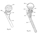
- the acetabulum is typically prepared using a hemispherical reamer to remove cartilage down to bleeding bone. Once the acetabulum is prepared, an acetabular component is implanted, either by cementing in place or press fitting for bony ingrowth.
- the surgical exposure which may be between six and twelve inches in length, may result in extensive trauma to the soft tissues surrounding the hip joint along with the release of muscles that insert into the proximal femur.
- the prepared bony surfaces are technically referred to as the acetabular fossa, femoral canal and metaphyseal region of the femur.
- a femoral trial which may be a broach in some systems, is placed in the proximal femur along with a trial femoral head and neck, and an trial is placed into the acetabulum to facilitate trial range of motion and evaluation of hip stability prior to placement of the final total hip implants.
- a system to enable minimally invasive total hip arthroplasty that will minimize soft tissue trauma and accelerate postoperative rehabilitation is needed. Further, because minimally invasive techniques inherently limit observation of the surgical site, compromising visualization of the prepared bony surfaces, a device is also needed fo r inspection of the prepared bony surfaces.
- a device is also needed fo r inspection of the prepared bony surfaces.
- bone debris and blood will gather in the surgical site and require removal from time to time to visualize the acetabulum.
- an acetabular component is implanted.
- a variety of acetabular components such as cemented UHMWPE cups, cemented or press fit metal shells with UHMWPE, metal, or ceramic bearing liners are presently used.
- an impaction device is needed that allows for impaction of the acetabular component with the hip reduced or articulated for use with a minimally invasive exposure for total hip arthroplasty. It may also be desirable to use a surgical navigation system to prepare the joint surfaces and position the implants.
- the present invention provides a system and method for total joint replacement that involves minimally invasive surgical procedures including an implant system that restores individual patient joint kinematics.
- the instruments and implants disclosed accomplish accurate bone and soft tissue preparation, implant orientation and implant fixation through limited surgical exposure.
- the present invention provides a method of appropriately sculpting the articular surface of a first b one that normally articulates with a second bone and implanting a prosthetic device.
- the method involves attaching a bone sculpting tool directly or indirectly to the second bone with the tool in bone sculpting engagement with the articular surface of the first bone, and then sculpting the articular surface of the first bone with the joint reduced and if indicated moving one bone with respect to the other.
- the bone sculpting tool may be attached to a mount that is attached directly or indirectly to the second bone. In some situations, it may be desirable to distract the first bone from the second bone during surgery.
- the bone sculpting tool may also be attached to a bone mount that is directly or indirectly attached to or integral with a stem, tr ial, reamer or broach implanted in the medullary canal of a bone.
- the implant system is comprised of implants and instrumentation that provide intraoperative surgical options for articular constraint and facilitate proper align ment and orientation of the knee to restore kinematics as defined by the individual patient anatomy.
- the implants provide a surgeon intraoperative options to reconstruct various degrees of joint stability via selection of fixed or mobile bearing components for each compartment of the knee (medial joint, lateral tibiofemoral joint and patellofemoral joint).
- the range of implants may cover only one compartment or each compartment of the knee and may include combinations of fixed and mobile bearing configurations.
- the femoral component is generally a unitary piece and the tibial component is a unitary piece.
- the femoral side may be resurfaced by two or three components and the tibial s ide may be resurfaced by two components or a unitary piece.
- the components may be aligned and or joined one to another within the confines of the joint.
- the components of the femoral side may be comprised of a plurality of flexible segments.
- orientation of the implant construct with respect to the supporting bones is such that the forces transferred through the implant are generally normal or perpendicular to the bony support surfaces.
- orientation of the implant components with respect to one another is such that each modular component restoring the femoral articular surfaces is properly aligned with the other modular components on the femoral side to ensure proper tracking of the implant construct.
- each modular component restoring the tibial articular surfaces is properly aligned with other modular components on the tibial side to ensure proper tracking of the implant construct.
- the surgical instrumentation prepares the articular surfaces of a synovial joint from a single point of reference to allow the introduction of separate components for the medial and lateral tibiofemoral compartments, and the patellofemoral compartments with precise orientation.
- the instrumentation provides bony resections in accordance with such alignment and orientation requirements. The positioning is important for proper restoration of anatomic alignment of the knee joint and for proper orientation of the components to one 'another.
- the method of the current invention enables the articular bone surfaces to be sculpted according to the individual physiology of each patient to restore as much as possible the natural junction of the joint.
- a bone sculpting tool is attached to one of the bones of a joint, and the tool sculpts the articular surface of the other bone as the joint is articulated.
- the present invention provides a method of appropriately sculpting the articular surface of a first bone that normally articulates with a second bone.
- the method involves providing an apparatus comprising a bone sculpting tool attached to a bone mount, attaching the mount rigidly to the second bone with the tool in bone sculpting engagement with the articular surface of the first bone, and then sculpting the articular surface by articulating one of the bones with respect to the other.
- a distractor may be provided wi th the apparatus.
- a distraction force provided between the femur and the tibia during the sculpting procedure accounts for material that has worn away from the articular surfaces.
- Use of a distraction force generally re -establishes normal alignment of the joint.
- Ligament releases may be carried out to restore alignment either prior to preparing the joint surfaces or following the preparation of the joint surfaces with bone sculpting instruments.
- a distractor may be u sed preoperatively to assess the range of motion of the joint and patient kinematics.
- the invention provides an apparatus for sculpting the articular surface of a first bone that normally articulates in a predetermined manner with a second bone.
- the apparatus comprises a bone sculpting tool, a mount attachable rigidly to the second bone, and an adjustable attachment attaching the sculpting tool to the mount and enabling the position and orientation of the tool to be adjusted into bon e-sculpting proximity to the articular surface so that the articular surface is sculpted as the second bone is articulated with respect to the first bone.
- a plurality of bone sculpting tools may be used where the tools are positioned either o n individual mounts or on a single mount to support the plurality of tools.
- the invention also provides implants for replacing the surfaces of the joint between the first bone and the second bone.
- the implants are specifically designed to fit through mini mally invasive incisions and incorporate any and all combinations of fixed and mobile bearing inserts or parts. Since the surgical procedure preferably is performed through minimally invasive incisions the implants are designed to fit through such incision s and be either oriented or joined within the joint.
- the implants include a second bone baseplate and a first bone implant.
- the second bone baseplate may be either one piece to cover most of the prepared surface of the second bone as relates to the joint, or separate baseplates as have been used with mobile and fixed bearing prosthetic components.
- the second bone baseplate may accommodate separate fixed and mobile bearing inserts.
- the first bone implant is comprised of a plurality of components to replace the bearing surface of the first bone.
- a portion of the first bone implant may be configured of a plurality of flexible segments bonded in place. Such a configuration permits the articulation of the second bone to the first bone to mould the flexible segments in appropriate position.
- the invention provides a method of appropriately replacing the articular surface of a first bone that normally articulates with a second bone.
- the method involves providing an apparatus comprising a bone sculpting tool attached to a bone mount, attaching the mount rigidly to the second bone with the tool in bone sculpting engagement with the articular surface of the first bone, and then sculpting the articular surface by articulating one of the bones with respect to the other.
- the articular surfaces are resurfaced with appropriate minimally invasive implants wherein the implants are joined within the confines of the joint ca vity.
- a plurality of flexible segments are provided to resurface a portion of the first bone. The flexible segments are set in an adhesive along the resected surface of the first bone.
- the invention may be used for replacing the surfaces of a femur and a tibia.
- a femoral implant having a plurality of components and a tibial baseplate are provided.
- the tibial baseplate may have a fixed bearing attachment as well as a mobile bearing attachment.
- the invention When applied to total hip joint replacement, the invention may be used for replacing the surfaces of a femur and through a minimal incision and with minimal disruption of structures about the hip.
- a typical incision for a minimally invasive total hip procedure is between two and four inches in length. It is noted that there may be some variation in incision length due to patient physiology, surgeon preferences, and/or other factors; the stated range is illustrative, not limiting.
- care is taken to approach the joint capsule by separating tissues between muscle groups, rather than sectioning specific muscles.
- an acetabular component such as a press fit shell, is implanted following preparation of the acetabulum.
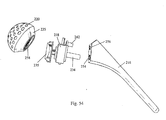
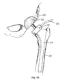
- An impaction device is provided that allows for impaction of the component with the hip reduced or articulated in order to fully seat a press fit acetabular component into support bone of the A surgical navigation system for pos itioning the acetabular component may be used with the impaction device.
- the hip is accessed through an incision adequate to expose the trochanteric fossa and allow resection of the femoral neck and removal of the femoral head and neck segment.
- the femoral canal is accessed through the trochanteric fossa and trochanteric region.
- Reamers, rasps and other devices as are known to those skilled in the art are used to prepare the proximal femur to receive a femoral implant by a sequence of reaming and broaching steps.
- the intramedullary canal and retained area of the femoral neck and trochanteric region are used to support the MIAR (Minimally Invasive Reamer) system to prepare the acetabulum.
- MIAR Minimum Invasive Reamer
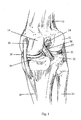
- FIG. 1 illustrates the general anatomy of the knee joint.
- the femur 10 has the lateral femoral condyle 12 and the medial femoral condyle 14 on its knee joint articul ating surface.
- the tibia 16 has the lateral meniscus 22 (generally opposite the lateral femoral condyle 12) and the medial meniscus 20 (generally opposite the medial femoral condyle 14) on its knee -joint articulating surface.
- the ligaments include the ante rior cruciate ligament 24, the posterior cruciate ligament 28, the medial collateral ligament 26 and the lateral collateral ligament 27.
- the medial tibial condyle 30 and the lateral tibial condyle 32 support the menisci 20 and 22, which in turn support the femur 10. Additionally, the fibula 34 engages the tibia 16.
- a total knee joint replacement involves replacing the articular surfaces of the lateral femoral condyle 12, the medial femoral condyle 14, the medial tibial condyle 30 and the latera I tibial condyle 32.
- the lateral meniscus 22, and the medial meniscus 20 are removed.
- neither the collateral ligaments 26 and 27 nor the cruciate ligaments 24 and 28 are disturbed.
- the collateral ligaments 26 and 27 may be partially taken down to provide appropriate tension adjustments to the patient's knee after joint replacement has been completed.
- Figure 2 illustrates the conventional midline incision 40 for a total knee replacement surgery.
- the incision 40 extends vertically substantially above and below the articulating surface between the femur and the tibia. Typically, the incision is roughly 8 to 15 centimeters in length.
- the incision 40 must be large enough to expose the entire knee joint articular surfaces with the patella subl uxed or dislocated. Additionally, the incision must accommodate insertion of components that fully cover the end of the femur, the top of the tibia and the undersurface of the patella.
- the maximum number of components implanted would include femoral and ti bial components for the lateral tibiofemoral compartment, femoral and tibial components for the medial tibiofemoral compartment and femoral and patellar components for the patellofemoral joint.
- the lateral femoral condyle and the patellar gr oove may be covered by a common implant.
- a transverse incision 42 extending horizontally along the knee joint is one option for the procedure of the present invention.
- the incision 42 may be vertically opened to expose the joint surfaces of the compartment and the lateral tibiofemoral compartment without dislocating the patella. This maintains the patella in contact with the femur during the procedure.
- the components of the instrumentation as well as the implant are sized for minimal invasiveness and, therefore, may be accommodated by the small incision.
- the reduced trauma resulting from a smaller incision generally results in faster and better rehabilitation, which in turn generally increases the efficacy of the knee implant.
- Figure 4 depicts an alternate incision format for use with the present invention.
- Two parallel vertically extending incisions 44 and 46 may be formed on either side of the patella. These incisions 44 and 46 are relatively short and the invasiveness is similar to that of the horizontal incision in Figure 3.
- Each incision 44 and 46 is separately extended through the joint capsule to expose the medial and lateral tibiofemoral compartments without dislocating the patella.
- the instrumentation of the current invention generally calls for resecting the tibia at the lateral tibial plateau and the medial tibial plateau.
- the instrumentation can be used to resect the distal femur thereby creating an extension space to accommodate bone sculpting instrumentation.
- This resection may be done by methods known by those skilled in the art, using a resection guide, saw, etc.
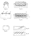
- a milling burr 43 may be advanced directly into the tibia 1 6.
- the milling burr 43 should stop at or short of the posterior cortical wall 54.
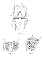
- Figure 5 shows a cross sectional view through the cavity created in the tibial plateau by the milling burrs 47 of Figures 6 and 7.
- the cutting de vice may be a single milling burr 45 affixed at the forward end of a guide element 49.
- the milling burr 45 of Figures 6 and 7 has its axel in a medial to lateral direction when preparing the tibial plateau.
- the radius of the milling burr leaves a corresponding radius between the floor and posterior wall of the cavity created.
- the cutting device may comprise a plurality of milling burrs 47.
- the milling burrs 47 of Figures 8 and 9 prepare a corner between the floor a nd posterior wall of the cavity created in the tibial plateau. The corner thus prepared may distribute stress uniformly into the supporting bone.
- the milling burrs 47 create a radius equivalent to the radius of the burr between the sidewalls of the cavity and the posterior wall. Such a radius is easily accommodated by the tibial implant design. While Figures 8 and 9 depict a cutting device having a plurality of milling burrs, the cutting device may be configured with one milling burr.
- Figure 10 shows an an terior view of the bone resections 50 and 52 that are made in the tibial plateau, generally 51.
- the floor of the medial resection 50 and the floor of the lateral resection 52 are preferably parallel and co -planar to ensure proper alignment and orientation of the medial and lateral tibial components.
- the external tools used to guide the tibial cutter may provide relative alignment between the medial and lateral resections.
- the medial and lateral cavities in the tibial plateau may be prepared sim ultaneously by having two guide elements 49 linked together by a hinge that restrains the medial and lateral milling burrs 47 in a common plane.
- the external tools may further provide a positive reference to the posterior aspect of the tibial plateau to en sure that the resections do not penetrate the posterior cortical wall.
- the bone resections are shown to have a generally rectangular cross - section.
- any cross -section to which a bone sculpting tool may be mounted may be used.
- an arcuate cross-section is acceptable.
- Figure 11 shows a top-view of bone resections 50 and 52 in the tibia 16.
- a cross-sectional view of the tibia 16 with a cavity machined into the plateau is depicted in Figure
- the bone resection 50 should stop at or short of the posterior cortical wall 54.
- a bone sculpting tool for example, a femoral cutter, generally 60, is placed in a mount and rigidly attached to the cavity created in th e tibia.
- Rigid attachment generally means providing sufficient stability to prevent relative motion between the mount and the tibia during articulation. Such stability may be provided through mere placement of the device in the tibial resection.
- the femora I cutter is designed to reference the tibial resections 50 and 52 when making the femoral resections.
- the mount is a cradle 62 and is set in the resected tibia.
- Cutting elements 64 are mounted in the cradle 62 and a flexible shaft 66 connects the cutting element to the motor 68 of Figure 14.
- the device fits into the resections 50 and 52 in the medial and lateral tibial plateaus.
- a cutting element is rigidly held against the femoral condyle and the guide surface of the device sets the depth of resection.
- a second cutting element may be placed in the opposite tibial resection.
- two cutting elements may be placed in the prepared tibial plateau, one in the medial cavity and one in the lateral cavity, and may be used to simultaneously resect the femoral condyles.
- the cutting elements may be linked together by a hinge mechanism 65 to further maintain the cutting elements in a common plane whi le preparing the femoral condyles (Reference is made to Figures 32 and 33).
- the tool in knee surgery, may be mounted to the tibia with the sculpting surface of the tool in engagement with a condylar surface of the femur, that is, one or both of the condyles.
- the sculpting tool appropriately sculpts the articular surface of the femur in a manner that is dependent upon the individual physiology of that patient's knee, that is, upon the collateral ligaments, the patellar tendon, etc.
- the knee joint capsule is surgically accessed without lateral dislocation of the patella, thereby permitting normal flexion of the knee during the sculpting process.
- the patient's individual physiology and the interplay between the patient's soft tissues and bone work to guide the device used for sculpting cartilage and bone from the end of the femur and/or tibia as they relate to the knee.
- the tibia travels around the end of the femur along a guided path that is controlled by the ligaments and soft tissues that surround and provide support to the knee.
- An alternate mount configuration involves an external fixture having burrs attached thereto.
- the external fixture may be of any configuration that supports the burrs in a position relative to the tibia for sculpting the femur.
- One example includes an external support member having an arm extending therefrom, the burr attached at the distal end of the arm.
- the bone-sculpting tool may be powered by a driving mechanism, for example, a motor.
- the motor may be an electric motor, a pneumatic motor, or a hydraulic motor integral with the cutting element.
- the cutting element may be driven by available surgical power instruments, such as surgical drills, Midas Rex and Anspaq hi speed drill/c utters, etc. Such equipment is available in pneumatic and battery operated forms.
- the cutting element may alternately be driven by a power source developed uniquely for this invention.
- the power source may be an electric or pneumatic motor. It may also be a hydraulic motor driven by sterile saline solution.
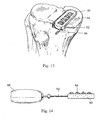
- the motor may be incorporated into the milling cutter, as illustrated in Figures 15 through 18.
- the vanes of the hydraulic motor are optionally machined as part of the axel of the milling burr element, or machined into the end face of the milling burr element.
- the housing 53 of the cutting device 55 includes a channel 57 for accommodating saline solution to drive the hydraulic motor.
- Figures 15 and 16 show an embodiment wherein the vanes of the hydraulic motor are incorporated into the wheel 59 at the distal end of the housing 53. It is also possible, as seen in Figures 17 and 18, to have the blades 61 of the cutting element 55 function as the vanes of the hydraulic motor in which case the saline solution is directed against the cutting element to force rotation.
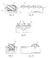
- FIGs 19 through 30 depict cross -sectional views of various cutting elements that may be used with the pre sent invention.
- Figures 19 and 20 show an end and side view, respectively, of one embodiment of a cutting element.
- Milling burrs 72 are placed in the mount 73 and orientated with the axels in a medial to lateral direction.
- multiple milling bu rrs are shown to provide contact with the femoral condyle as the knee is flexed and the tibiofemoral contact point moves distally.
- one milling burr may be placed in a position such that it remains in contact with the femoral condyle throughout knee flexion.
- the invention may be practiced with one or more milling burrs supported in the cradle.
- the cradle may be provided with shoulders 71 having skidding surfaces for co ntacting the femoral condyle.
- Figures 21 and 22 show an end view and a side view, respectively, of an alternate embodiment for a cutting element in which the milling burr 74 is contoured to provide a contoured resection in the femoral condyle.
- a contoured resection removes less bone and the bone remaining is generally stronger than bone deeper in the condyle.
- the milling burr 72 is oriented with its axel in an anterior to posterior direction. At knee ex tension, the tibiofemoral contact point is near the anterior end of the milling burr. As the knee is flexed, the contact point moves posteriorly and approaches the posterior end of the milling cutter.
- Figures 25 and 26 show three milli ng burrs 76,77, and 78 in parallel with orientated in an anterior to posterior direction.
- Such an embodiment provides for a broad resection of the femoral condyle in one pass or flexion of the tibia.
- the medial and lateral milling burrs 76 and may be of sm aller diameter than the central milling burr 77, as seen in Figure 27, to provide a smaller corresponding radius between the sidewalls of the cavity created in the femoral condyle and the floor of the cavity.
- Cartilage and bone of the femoral condyles may be removed in one or more passes of a shaving element 80 as shown in Figures 28 through 30
- the shaving element 80 is off set from the surface of the mount 81 so that a pre -determined amount of bone is shaved off of the femoral condyle with each pass or fl exion of the tibia.
- One or more shaving elements may be supported in the base of the cutting element.
- the articular surface of the femur may be sculpted according to the patient's individual physiology by articulating the tibia with reference to the femur.
- the method involves providing the apparatus having a bone sculpting tool attached to a bone mount, attaching the mount rigidly to the second bone with the tool in bone sculpting engagement with the articular surface of th e first bone, and then sculpting the articular surface by articulating one of the bones with respect to the other.
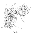
- Figure 31 illustrates the kinematics of the articulation of the tibia 16 about the femur 10.
- the bony resections of the medial and lateral fe moral condyles are made by securing the cutter to the tibia and articulating the tibia.
- the movement of the tibia in reference to the femur follows a J -curve because of the four bar linkage of the anterior and posterior cruciate ligaments, when both are in tact. In the absence of one or both cruciate ligaments, the movement of the tibia as the knee is flexed is controlled by the collateral and capsular ligaments.
- the bony support surface thus created in the medial and/or lateral femoral condyles will be shap ed and positioned relative to the kinematics of the given patient.
- Preoperative evaluation of patient x -rays may be used to assess deformity of the joint and appropriate spacing required to realign the joint. Additionally, spacers, for example balloons, may be used preoperatively to assess the range of motion of the joint and patient kinematics.
- spacers are placed between the bone structures to provide appropriate distraction and alignment of the joint.
- a distraction force provided between the femur and the tibia during the sculpting procedure may be used to account for material that has worn away from the articular surfaces.
- Use of a distraction force generally re -establishes normal alignment of the joint.
- Such spacers also tension the soft tissue structures to reduce the envelop of motion between the bone structures and increase transverse and rotational stability of the joint.
- the spacer may further be used to support the bone -cutting element during resection of the bone structures. Ligament releases necessary to restore appropriate limb alignment and ligament tension/balance may be performed prior to inserting the spacers.
- any one of a variety of devices may be used to maintain appropriate tension of the ligaments capsule and tendons.
- tensioning devices may include, but are not be limited to, gravity with the weight of the lower limb, intra -articular spacers, bladders, balloons, bellows, gear mechanisms, scissor mechanisms, other expandable devices or other elements th at might engage or attach to the opposing sides of the joint.
- the distraction force may be provided by an expanding base in the cutting element.
- a distraction device may also be useful in conjunction with a mount having skid surfaces on the shoulders. The shoulder allows the depth and shape of the femoral resection to be controlled both by the articulation of the tibia relative to the femur and the shape of the femur.
- spacers such as balloons may be provided in both the medial and the lateral resections.
- a balloon may be provided in the medial resection and a spacer, for example a bellows, having a cutter attached may be provided in the lateral resection.
- a bellows having a cutter attached may be provided in both the lateral and the medial resections.
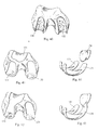
- Figures 32 and 33 provide closed and open depictions, respectively, of two cutting elements 61 and 63 linked by a hinge mechanism 65 to maintain the cutting elements in a common plane while preparing the femoral condyles.
- the hinge mechanism 65 allows adjustability of the placement of the two cutting elements 61 and 63 in reference to one another.
- the femoral sculpting tool of Figure 34 may be placed into the recesses in the tibial plateau.
- the hinge mechanism 65 enables adjustment of the tool arms 172 and 174 in the medial to lateral direction to accommodate the spacing of the tibial plateau resections and holds the tool arm s 172 and 174 in a common plane to ensure proper orientation of the femoral condyle resections with respect to one another.
- Cutting elements 180 are mounted into the tool arms 172 and 174 and are driven by a driving mechanism, for example, a pair of gear mechanisms.
- the gear mechanisms are driven by a common flexible drive cable 178 that drives a gear box providing torque to secondary drive cables 184 and 186.
- the surfaces of the cutting elements 182 are roughened, or have cutting flutes, to provide cutting of the femoral condyles.
- the knee femoral sculpting tool may be placed in the resections made in the tibial plateau 190.
- the cutting discs 180 are in contact with the femoral condyl es 188.
- the knee is flexed resulting in relative motion of the femoral condyles across the cutting discs, thereby resecting the medial and lateral condyles of the femur at the same time.
- Soft tissue structures spanning the knee guide the cutting motion along the normal kinematic motion of the given knee joint.
- the cutting discs 180 rotate in a transverse plane.
- Figures 37 and 38 provide end and top views, respectively, of a cutting element 100 supported in a platform 102 that is configured for elevation v ia fluid pressure applied to a distractor 104 that surrounds the cutting element 100.
- Applying pressure to the distractor 104 forces the milling burr into the femoral condyle to a predetermined depth as set by the top surface of the cutting element.
- the distractor 104 in combination with the top surface of the cutting element, ensures proper resection depth while tensioning the soft tissue structures spanning the knee joint.
- the benefit of tensioning the soft tissue structures is to reduce the envelop of motion of the knee, stabilize the knee and provide increased accuracy and repeatability of the femoral condyle resections.
- An alternate embodiment may use a spacer placed between the floor of the cavity created in the tibia and the bottom of the cutting element to provide a distraction force.
- Figure 39 shows balloon spacers 110 used to support the femoral condyles to distract the femur 10.
- Syringes or pumps 112 may be attached via hoses 114 to balloon spacers 110.
- Balloon spacers 110 are an example of an expandable spacer. Where an expandable spacer is used, pre -operative evaluation should be performed. During surgery an expandable spacer is placed between the bone structures to be resected.
- the cutting element may be housed in the dynamic spacer with th e cutting element adjustable to the dynamic spacer to set the depth of resection.
- the dynamic spacer may function under load control in which case a constant distraction force is applied between the bone structures throughout a range of motion, or under displacement control.
- the dynamic spacer houses the cutting element and the cutting element is held at a pre-set depth relative to the bone structure being resected while the joint is flexed and extended.
- the dynamic spacer allows the kinematics of the joint to define the resection path in each of the bone structures.
- the femoral cutter prepares resections in the femoral condyles for receiving femoral components of a knee implant.
- Figure 40 shows the bone resections 130 and 132 in the lateral and medial femoral condyles respectively.
- the patellar groove may be prepared in a similar fashion (not shown) with a femoral cutter secured to the patella.
- Figures 41 and 42 depict alternate embodiments of the bone resections with representative implants placed in the femoral condyle as may be desired.
- Implants The surgical procedure is preferably performed through minimally invasive incisions that do not necessitate subluxation or dislocation of the patella. Therefore, implants such as the femoral, tibial or patellar implants are designed that may be fit through minimally invasive incisions and either oriented or joined within the joint.
- the femoral and tibial implants may be attached to bone with conventional bonding methods such as, but not limited to, polymethylmethacrylate, or by direct attachment to bone as with, but no t limited to, a porous ingrowth surface.
- the tibial baseplate is optionally configured as one piece to cover most of the prepared surface of the tibial plateau as relates to the knee. If configured as a single platform, the tibial baseplate provides a capture mechanism for a fixed bearing or a mobile bearing insert for either the medial or lateral tibiofemoral compartment. As an option, a single platform is designed that provides a fixed bearing capture mechanism for the medial compartment and a mobile bea ring capture mechanism or a simple platform to receive a mobile bearing insert for the lateral tibiofemoral compartment. Since right and left tibial baseplates are required, the same baseplate may be used for a mobile bearing medial insert and a fixed bear ing lateral insert.
- the tibial implants may be configured as separate plateau baseplates for the medial and lateral compartments. These platforms might be oriented one to the other by an alignment instrument that dictates their orientation in relationship to each other and/or to the femoral components.
- the tibial baseplates may be fixed bearing and manufactured completely of polyethylene.
- fixed bearing tibial components 150 with a metal support tray 151, and mobile bearing tibial components 152 with a metal support tray 153 may be used in the same knee replacement surgery.
- the tibial baseplate may accommodate separate fixed and mobile bearing inserts in either or both medial and lateral compartmen ts.
- the femoral implants include a first component 133 to resurface the articulating surface of the medial condyle and a second component 131 to resurface the articulating surface of the lateral condyle.
- An optional third component 134 may be provided to resurface the femoral side of the patellofemoral joint.
- the convex surface of the femoral condyle is the bearing surface and interacts with the tibial bearing implants.
- the femoral component (s) may include a fin along its support or convex internal surface for upward driven implantation. The fin may be shaped as a web extending from one portion of the internal surface to another.
- the lateral femoral implant may be continuous with the patellar flange forming a unitary piece 136 that may be passed through a small incision.
- the lateral condylar component and the patellofemoral component optionally may be a single component 136 extending from the top of the patellofemoral groove and extending over the lateral condyle both distally and posteriorly, as seen in Figure 45.
- Figure 45 provides a side view of a femoral implant combining the lateral condylar component and the patellofemoral component into a single component 136.
- the bearing elements may be manufactured of ultra high molecular weight polyethylene but may also be manufactured of any suitable biocompatible material as known in the art.
- the bearing elements generally include three compartments: medial tibial condyle, lateral tibial condyle and patella.
- a choice of bearing elements is provided for either fixed or mobile bearing of each compartment.
- the surgeon would have at his discretion inserting either a mobile bearing or a fixed bearing insert into each of the tibial components, one medial and one lateral.
- the femoral components may include an alignment device to orient separate femoral components in relationship to one another and/or to the tibial components. Surgical navigation may be used in concert with bone preparation and component orientation.
- the femoral components are provided in a variety of sizes and optionally include components that are flexible t o provide optimum fit for minor variations in the shape of the prepared femoral condyles.
- Figure 46 is an illustration of an optional embodiment of the femoral condyle implants configured as flexible implants.
- the outer surface of the femoral condyle implant is a thin sheet of metal forming an articular surface, preferably of cobalt chromium alloy.
- the implant In order to provide uniform deflection in one plane, the implant is thin and of uniform cross section.
- the support surface of the femoral condyle implant is lined with molded bone cement, such as polymethylmethacrylate (PMMA or PMA), and spacers that are bonded to the articular surface.
- PMMA polymethylmethacrylate
- the spacers may be shaped as blocks or any other configuration suitable for molding in place during fabrication.
- the spacers are shaped to span the femoral condyle implant from side to side, in a coronal plane, while providing spaces between spacers at given intervals to facilitate mild flexing of the articular surface.
- Such flexing enables the flexible femoral condyle implant to conform to the unique shape of the prepared bony support surface in the femoral condyle, thereby taking full advantage of the kinematicly defined support surface.
- Such implants are provided in a range of sizes to accommodate individual patient physiology and to minimize the amount of flexing a given implant may make in conforming to the prepared surface. Hence, the distortion of the articular surface is minimal.
- the resected femoral condyle is covered with doughy bone cement.
- the femoral implant is placed and loaded against the resected femoral condyle until the bone cement cures.
- the preferred method for preparing the femoral condyle uses the tibia as a support for the milling cutter.
- the soft tissue structures of the knee provide the path of motion to move the cutter through the femoral condyle.
- the kinematics of the knee are well understood and defined. This approach necessarily results in a unique shape machined into each femoral condyle due to variations in soft tissue structures and bony structures from patient to patient.
- the femoral condyles may be ridged and of given size.
- Each implant is composed of a plurality of components 170.
- the components 170 are cemented in place with bone cement, which acts as a grouting material to fill the space between the implant and the supporting bone.
- Bone cement has been shown to provide long term implant stability when applied in thicknesses up to two millimeters. Hence, a range of implant sizes covers the range of femoral condyle sizes anticipated and the variation in shape anticipated.
- FIG 47 illustrates the general anatomy of the hip joint and a typical surgical approach 200 to the hip joint to expose the proximal femur 202 and the 204.
- traditional total hip replacement there are generally four surgical approaches to the hip joint. These include posterior approaches without trochanteric osteotomy, trans -trochanteric approaches, anterior approaches without trochanteric osteotomy, and Smith - Peterson approaches.
- posterior approaches without trochanteric osteotomy posterior approaches without trochanteric osteotomy
- trans -trochanteric approaches anterior approaches without trochanteric osteotomy
- Smith - Peterson approaches Such approaches are described in detail in various orthopedic reference texts such as " Operative Orthopedics" by M. W. Chapman, MD, J. B. Lippincott Company, 1988 .
- a direct lateral approach is commonly used for total hip arthroplasty.
- the musculature disrupted may include the short internal and external rotators, tensor fascia femoris, quadratus femoris, piriformis, and on occasion part of the gluteus maximus, and the gluteus maximus.
- the incision 206 is typically 6 cm as shown in Figure 48. While 6 cm, or 2 -4 inches, is a typical length for a minimally invasive surgical incision, there may be some variation due to patient physiology, surgeon preferences, and/or other factors.
- the surgical approach involves separating the gluteus maximus muscle through blunt dissection to gain access to the hip joint capsule and the trochanteric fossa. Muscle disruption is usually limited to release of the piriformis tendon at the trochanteric fossa. It should be noted that th ere are variations to the surgical approaches described that are known to someone skilled in the art.
- Figure 48 illustrates a minimally invasive surgical approach to the hip joint.
- the general approach is posterior, and the musculature disrupted includes release of the piriformis tendon.
- the incision is just large enough to expose the femoral head and acetabulum, and to enable placement of a hemispherical reamer 208, drive mechanism 210, and femoral broach 212.
- a total hip replacement surgery involves exposing the hip joint through a large incision to provide the surgeon full visualization of the hip joint and the region and access for surgical power instruments.
- the femoral head is removed and the femoral canal is reamed and broached to prepare the bony surface to support the hip stem.
- the stem may be cemented in place or press fit for bony ingrowth.
- the acetabulum is prepared, most typically using a hemispherical reamer attached to a surgical hand drill to remove cartilage down to bleeding bone.
- the surgical exposure as shown in Figure 52 generally ranges between eight and twelve inches in length and may result in extensive trauma to the soft tissues surrounding the hip joint.
- the MIAR of the present invention for use with hip replacement surgery, is either a modular or non-modular construct comprising a femoral trial 216, a drive mechanism 218 (either integral or separate) and a hemispherical reamer 220 or similar device for removing cartilage and bone from the acetabular fossa.
- the hemispherical reamer 220 or similar device includes an attachment component (not shown) for attaching either to the femur, directly or indirectly, or to a mount that itself is attachable to the femur, directly or indirectly.
- the procedure requires only a minimal release of muscles and tendons and, consequently, minimal trauma to muscles and tendons that attach to the proximal femur.
- the MIAR system uses a drive mechanism anchored to or mounted on a device such as a reamer, broach, or other suitable device that i s secured to one bone and, with the joint reduced or placed in position of reduction, may be activated to prepare, with a hemispherical reamer or suitable bone sculpting tool, the opposite side of the joint to receive artificial components.
- the femoral head is removed either before or after the femoral canal is reamed and broached to prepare a bony surface to support the hip stem or broach to be inserted.
- the minimally invasive acetabular reamer is mounted to the broach, re amer, trial femoral component or other device inserted into the proximal femur. It is possible to attach the MIAR directly to the proximal femur, however the instruments and the femoral implant provide an advantageous support structure as these instruments , such as rasps, broaches, trials or the implant, conform closely to the prepared bony surface and provides a rigid metal structure to which the MIAR may be mounted.
- the MIAR is directly or indirectly attached to the femoral broach that is secured within the proximal femoral canal.
- rasps, trials, broaches, implants and stems are used interchangeably in relation to the system. Additional embodiments include attachment of the MIAR directly to the femur, the femoral trial or the femoral implant.
- the reamer head is placed into the acetabulum.
- the MIAR is activated to initiate cartilage and bone removal as the femur is positioned.
- the operating surgeon controls the MIAR by placing and/or moving the leg as necessary to create a spherical reaming of the acetabulum. Surgical navigation may be utilized.
- the femoral trials are available in an array of sizes to accommodate the size range of the proximal femur.
- the hemispherical reamers are available in a range of diameters to accommodate the size range of the acetabulum.
- the drive mechanism is interchangeable amongst the femoral trails and amongst the hemispherical reamers.
- An alternate embodiment includes a drive mechanism for each femoral trial or groups of trials. The trials may be grouped by size, or by right and left. The example given is for the MIAR attached directly or indirectly to a femora I rasp. Similar combinations are possible when the drive mechanism is directly or indirectly attached to a femoral trial or femoral implant.
- An example of a procedure according to the present invention includes the following steps: the appropriate femoral trial is placed into the prepared proximal femur; the drive mechanism is placed onto the proximal aspect of the femoral trial followed by placement of the appropriate sized hemispherical reamer onto the drive mechanism; the hip is reduced and the reaming system is activated to prepare the acetabulum.
- the MIAR is not modular, it is placed as a unit, the hip is reduced, and the reaming system is activated.
- the acetabular reamer 220 attaches to the drive mechanism 218 at the support plate 235, which provides quick attachment to the drive mechanism 218.
- the reamer is preferably rigidly supported on the femoral side such that sufficient stability is provided to prevent relative motion between the MIAR and the femur during articulation. Such stability is generally provided through the placement of the broach 216, femoral trial or femoral implant in the femoral canal.
- Figure 49 illustrates an embodiment of a MIAR in accordance with the present invention.
- Support for the MIAR is provided by a femoral broach 216.
- the drive mechanism 218 is supported by the femoral broach 216.
- Figure 49 further shows the drive shaft 240 of the drive mechanism 218 supported in the drive mechanism housing, which is supported by the femoral broach 216.
- the drive mechanism 218 may use a worm 238 and worm gear 236 combination, bevel gears, spur gears, belts or chain drives or other suitable mechanism to transfer rotation or oscillation to the acetabular reamer.
- a worm gear 236 is attached to the drive shaft 234 which in turn is driven by a worm (behind the worm gear).
- a worm and worm gear combination represents only one possible drive mechanism that may be used to drive the ace tabular reamer and is intended to be illustrative but not limiting. Any other drive mechanism known to those skilled in the art may be used with the present invention.
- Figure 51 depicts the worm 238 supported by an input drive shaft 240.
- a flexible drive cable 228 is attached to the drive shaft 240.
- a sleeve mounted to the drive mechanism housing may extend through the surgical incision and contain the drive shaft 240 with the flexible cable 221 attached outside of the su rgical incision. Torque generated by the drive mechanism is reacted between the drive mechanism and the femoral trial by a rotational stop 242. (See Figure 8.)
- the acetabulum is prepared by rotating or oscillating a hemispherical reamer within the acetabu lum.
- the hemispherical reamers may be reamers, cutters, or other devices used for removing cartilage and bone from the acetabular fossa.
- non-mechanical cutting instruments such as lasers, water jet cutting, ultrasonic probes, chemical or oth er devices to remove tissue can be used.
- such devices involve rotation or oscillation of the reamer with the device supported by the femur.
- the MIAR may be self -contained with an internal power source to drive the reamer, or may have an external power source to drive the reamer.
- the motor 222 may be internal to the drive mechanism or may be external with torque transferred to the drive mechanism via appropriate shaft or connection.
- the drive mechan ism may be constructed of mechanical components such as gears, cams, levers, belt and pulleys or chains.
- Power sources for the drive mechanism to drive the reamer include fluid to drive a hydraulic motor, gas to drive a pneumatic motor, electrical to drive an electric motor (either integral to the femoral trial or via flexible drive cable connecting the motor to the drive mechanism), solenoid or other suitable power source to provide rotation or oscillation to the reamer.
- the drive mechanism may be driven by available surgical power instruments, such as surgical drills, Midas Rex and Anspaq hi speed drill/cutters, etc. Such equipment is available in pneumatic and battery-operated forms.
- the drive mechanism is driven by an external power source transferring torque through a flexible drive shaft.
- the power source may be housed within the femoral trial or broach.
- the drive mechanism may be configured for use with any one of the attachment mechanisms provided by various manufacturers of total hip systems to attach trial necks to femoral trials.
- the attachment thus may be a peg in groove, a peg in hole, a conical taper, a screw fit, or a threaded attachment.
- the drive mechanism is designed to attach to a femoral trial or rasp/trial provided with the total hip system with which the MIAR is being used.
- the proximal surface of the drive mechanism is designed with a quick attach mechanism that fits an array of acetabular reamer sizes.
- the drive mechanism is supported by the femoral taper that supports the femoral head implant or implant trial.
- the femoral stem trial is placed into the prepared femoral canal and the appropriate femoral neck trial is pl aced onto the stem trial.
- the drive mechanism is placed onto the femoral neck trial taper and the appropriately sized reamer is directly or indirectly attached to the drive mechanism.
- the femoral stem trial and femoral neck trial may be integrally formed.
- the femoral canal is prepared and the appropriately sized femoral stem is selected based on the patient's femoral anatomy.
- the femoral stem implant is placed into the prepared femur and the drive mechanism with appropriately sized acetabular reamer is placed onto the implant to prepare the acetabulum.
- the drive mechanism may be integral to the femoral trial or the acetabular reamers.
- the hemispherical reamers are modular and allow changing reamer si zes during the procedure.
- the appropriate femoral broach 216 with integral drive mechanism in this case a hydraulic motor 222, is placed into the prepared proximal femur and the appropriately sized hemispherical ream er 220 is directly or indirectly attached to the broach via the drive mechanism.
- the trial stem includes a drive mechanism 222 that is housed within the proximal aspect of the broach 216.
- the drive mechanism 222 which may be a hydraulic motor within the b roach, rotates the drive shaft 226 and support plate 235 which in turn rotate the acetabular reamer 220 to prepare the acetabulum.
- the appropriate acetabular reamer 220 with integral drive mechanism 218 is placed into the acetabular fossa 232 and directly or indirectly attached to the femoral trial 216.
- Acetabular preparation is performed with the hip joint articulated (reduced).
- Figures 49, 50, 51, 53 and 54 illustrate the mechanical drive mechanism used in one embodiment of the MIAR system.
- Figure 53 shows the MIAR placed into the proximal femur 230 with the hemispherical reamer 220 in contact with the 232.
- Figure 54 illustrates an exploded, view of one embodiment of the MIAR system.
- the drive shaft 234 extending distally from the drive mechanism 222 passes into receiving hole 254 to attach the drive mechanism 222 to the broach
- the anti -rotation pin engages the receiving hole 256 to add stability and rotational resistance between the drive mechanism and broach.
- the re amer 220 attaches to a support plate 235 that is part of the drive mechanism 218.
- the surface 258 of the reamer 220 conically locks to the support plate 235.
- the acetabular reamer is assembled in a collapsed state to allow ease of reduction of the hip joint with the MIAR system in place.
- the reamer is elongated from the femoral housing or from the drive or gear mechanism of the This elongation may be accomplished by a variety of devices, for example shim plates, spacers or other suitable device placed between the elements.
- the MIAR may be elongated by means of pneumatic pressure, lead screws or other power sources. The manner by which the MIAR is elongated is not critical to the invention and any suitable device or me thod may be used. When sufficient resistance is encountered by the joint capsule and/or other soft tissue elements about the hip, the MIAR is activated to initiate acetabular bone preparation.
- acetabular reaming is enhanced by pressure created through tensioning the soft tissue elements.
- gas pressure first elongates the MIAR construct. After a specified amount of resistance is encountered to elongation, pneumatic pressure is transferred to elements that generate torque to turn the acetabular reamer.
- an acetabular implant is secured to the supporting bone, usually by either bone cement or press-fit.
- the bone surface is oversized relative to the implant size.
- the bony surface and the implant are covered with bone cement.
- the implant is then placed into the acetabulum and pressed into position forming a uniform layer of bon e cement between the acetabular component and supporting bone.
- the bone surface is line -to-line or slightly undersized relative to the implant size. The implant is impacted into place in the supporting bone.
- a straight handled impactor is commonly used to impact the acetabular component.
- the extensive exposure typically used in traditional total hip surgery provides the clearance to align the impactor relative to the acetabulum.
- the incision is too small to allow proper orientation of a standard straight handled impactor.
- Use of a standard impactor requires making a second incision to pass the impactor through muscle and tissue in the correct orientation relative to the acetabulum.
- the acetabular component must be positioned properly to provide normal function and to prevent dislocation of the hip joint. Making a second incision and disrupting more muscle is contr ary to the goal of a minimally invasive procedure.
- the current invention includes a device designed to directly or indirectly att ach to the femoral trial and provide an impaction force to properly seat the implant.
- a variety of components and methods for placement thereof may be used.
- Example components for implanting in the acetabulum include, but are not limited to, cemented shell s or press fit cups.
- the impaction device preferably includes a pneumatic impaction hammer 260 to the femoral broach 216 and an optional attachment component for attaching to the shell 252 of the component.
- the impaction device 260 and acetabular component 252 may be placed into the surgical site independently and assembled in the operative site. Alternatively, the impaction device 260 and acetabular component 252 may be assembled prior to placing the impaction device onto the broach 216. With the acetabular shell directly or indirectly attached to the impactor and the impactor secured to the femoral broach, the shell is placed into the acetabulum by reducing the hip joint.
- the broach, femur and mass of the leg serve as counter weight s to counteract the force of the impaction device.
- An additional counter weight may be directly or indirectly attached to the impaction device via a connection shaft extending outside of the incision and attaching to a weight or an external resistance to impaction forces.
- the impaction device may be powered by a pneumatic impaction hammer, a hydraulic piston, a linear actuator or solenoid, an electromechanical device, a spring activated device or any other suitable force generating mechanism.
- the power sou rce may originate outside of the operative site or may be integral with the impaction device.
- a hand held impactor with a handle angled to allow access through a minimally invasive incision may be used to impact the acetabular component.
- the impactor is a single ended air driven piston and cylinder as shown in Figure 57.
- the back face 292 of the impactor housing 268 is configured to attach to the broach previously described. Within the housing is a primary pist on 282 that travels in a primary cylinder 294.
- a push rod 286 of a secondary piston 280 engages a retaining groove 288 in a primary piston 282.
- the secondary piston 280 is held in an extended position by a secondary spring 278. Air pressure is applied via a primary tube 284 to the back of the primary piston 282 to charge the system.
- the primary piston 282 is held in place by the push rod 286 of the secondary piston 280. Air pressure is applied to the secondary tube 276 to p ull the push rod and the secondary piston 280 out of the retaining groove 288 in the primary piston 282, thereby releasing the primary piston 282 to impact the top surface of the cylinder 298.
- the impaction force is carried through the impactor housing 268 and delivered to the acetabular shell (not shown) via a cup adaptor 264.
- the cup adaptor 264 has a threaded end 290 that engages the acetabular shell.
- the other end of the cup adaptor 264 has a box shaped recess 300 that fits over a mating prominence 270 on the top surface of the impactor housing 268.
- the pressure to the primary tube 284 is released and the primary piston 282 is forced back into a retracted position by a return spring 274.
- the air pressure to the secondary tube 276 is released and the secondary piston 280 is pushed back into locked position by a secondary return spring 278. Pressure is applied to the primary tube 284 to charge the impactor and the cycle i s repeated.
- the cup impactor 260 and broach may be assembled outside of the surgical site, then placed into the prepared proximal femur.
- the broach may first be placed into the proximal femur, then the cup impactor 260 attached to the broach.
- the cup adaptor 264 is attached to the cup implant and the recess 300 in the adapter is placed over the mating prominence 270 on the top of the cup impactor.
- the hip joint is reduced, placing the acetabular shell into the acetabulum.
- An alignment guide (not shown) is attached to the cup impactor to aid the surgeon in properly orientating the shell with respect to the pelvis.
- a surgical navigation system may be used to position the acetabular shell by referencing the cup impactor and the acetabulum. Once in position, the shell is impacted into the acetabulum by triggering the cup impactor with successive impactions.
- the trigger releases one impaction, then the cup impactor resets for a further impaction as necessary.
- the trigger releases continuous impactions for the duration that the trigger is on.
- the impaction device is suitable for use in placing an implant other than an acetabular component.
- the impaction device may be used for seating an implant in a second bone in any joint replacement wherein the implant may be placed on the impaction device, aligned with a second bone, and force imparted to the implant, the force bei ng reacted with the first bone and the second bone.
- a typical surgical procedure for the MIAR is as follows: Using the instrumentation shown, the articular surface of the acetabulum may be sculpted according to the patient's individual physiology by articulating the femur with reference to the acetabulum.
- the method involves providing an apparatus having a bone sculpting tool directly or indirectly attached to a bone mount such as a femoral trial stem, attaching the mount rigidly to the femur with the tool in bone sculpting engagement with the and then sculpting the by articulating the femur with respect to the joint.
- the hip joint is a ball in socket joint, hence rotation of the femur while supporting the in a spherical preparation of the acetabulum.
- the MIAR having a suitable reamer and drive mechanism, may be placed into the acetabulum to remove bone without rotating the femur.
- the trochanteric fossa is surgically accessed with minimal disruption of muscle and tendon insertions to the trochanter and surrounding area.
- the approach may be at the posterior border of the gluteus maxims and minimus, anterior in the interval between the sartorius and the rectus, or a direct lateral exposure.
- the hip may be dislocated posteriorly if a posterior approach is used or anteriorly if either a lateral or anterior approach is used. Alternatively, the hip may remain reduced while the femoral canal is prepared and the femoral neck is resected.
- the femoral neck is resected and the femoral head is removed.
- the resection and removal may be performed with conventional cutting devices such as oscillating saws.
- the femur is oriented to align the femoral canal with the incision.
- the femoral canal is prepared using sequential reaming and broaching. Bony preparation is per the technique specified for the particular total hip stem being used and at the surgeon's discretion.
- the drive mechanism is directly or indirectly attached to the femoral trial.
- the drive mechanism is designed to mount directly onto the femoral trial.
- the acetabular reamer is directly or indirectly attached to the drive mechanism.
- the appropriate reamer is selected by the surgeon.
- the surgeon may choose to measure the diameter of the removed femoral head as an aid in selecting the most appropriately sized acetabular reamer.
- the surgeon may choose to use surgical navigation.
- the hip joint is reduced and the hip is articulated with the drive me chanism and acetabular reamer in place. Elongation of the MIAR construct is optionally carried out to appropriately tension the soft tissue elements about the hip.
- the drive mechanism is activated to prepare the acetabulum. If necessary, the femur may be advanced while the hip joint is manipulated to ensure spherical and uniform reaming of the may be used to check the orientation and depth of the acetabular reamer.
- the depth and uniformity of reaming may be checked periodically during the procedure. This may be done by dislocating the hip, removing the reamer and attaching the illumination and irrigation devices (or a combined illumination and irrigation device) to the femoral trial. The hip is reduced with the illumination and irrigating devices in place and the operative site is cleared with irrigation and suction. The prepared surface of the acetabulum may then be inspected. After inspection, the illumination and irrigation devices are removed and the drive mechanism and reamer are replaced. Alternatively, the depth of reaming may be assessed under imaging of the hip joint.
- the articulation of the hip joint to prepare the may be repeated with sequentially larger reamers until the appropriate size is reached. Further, the size and preparation may be checked with the illumination and irrigation devices as necessary. Once the appropriate size is reached, the acetabular reamer and the drive mechanism are removed.
- an appropriate acetabular component is implanted.
- the appropriate acetabular component may be pre -selected or may be selected after surgical preparation of the acetabulum. If the desired component is a cemented cup, the cup is cemented in place.
- a cup impactor is attached to the broach and placed into the prepared proximal femur.
- the broach may be placed in the prepared femoral canal first and then the cup impactor attached to the broach.
- the acetabular shell is attached to the cup adaptor and placed onto cup impactor.
- the hip joint is reduced and the shell is positioned in the acetabular fossa.
- An alignment guide is attached to the cup impactor to aid the surgeon in proper orientation of the shell during impaction.
- the cup impactor is triggered, thereby impacting the shell.
- An alternative technique for placing a press fit cup may use image guided surgery or an alignment device protruding from the incision.
- the guiding system is used to advance the cup into proper orientation.
- the minimally invasive acetabular impactor is activated to securely seat the cup into the Regardless of technique, after placement of the press fit cup, the impaction device is removed.
- a surgical navigation system may be used for positioning, aligning, and monitoring the cup or cup impactor during impaction. Cup monitoring includes real time evaluation of the cup position relative to anatomical landmarks captured by the surgical navigation system after preparing the acetabulum and before placing the cup so as to indicate cup seating and cup alignment.
- the acetabular liner is placed into the shell and a trial femoral neck and head are placed onto the femoral trial.
- the range of motion and hip stability are checked and the appropriate femoral implant is selected.
- the femoral trials are removed and the femoral component is implanted per manufacturer specifications.
- an apparatus and method for minimally invasive sculpting the articular surface of a first bone that normally articulates with a second bone is provided.
- a bone sculpting tool is provided on the tibia for sculpting the femur when the tibia is articulated with reference to the femur.
Applications Claiming Priority (3)
| Application Number | Priority Date | Filing Date | Title |
|---|---|---|---|
| US09/882,591 US6482209B1 (en) | 2001-06-14 | 2001-06-14 | Apparatus and method for sculpting the surface of a joint |
| US10/075,829 US6723102B2 (en) | 2001-06-14 | 2002-02-12 | Apparatus and method for minimally invasive total joint replacement |
| EP02742045A EP1416864B1 (fr) | 2001-06-14 | 2002-06-14 | Appareil permettant de sculpter la surface d'une articulation |
Related Parent Applications (2)
| Application Number | Title | Priority Date | Filing Date |
|---|---|---|---|
| EP02742045.4 Division | 2002-06-14 | ||
| EP02742045A Division EP1416864B1 (fr) | 2001-06-14 | 2002-06-14 | Appareil permettant de sculpter la surface d'une articulation |
Publications (3)
| Publication Number | Publication Date |
|---|---|
| EP1745764A2 true EP1745764A2 (fr) | 2007-01-24 |
| EP1745764A3 EP1745764A3 (fr) | 2011-11-30 |
| EP1745764B1 EP1745764B1 (fr) | 2015-12-23 |
Family
ID=26757331
Family Applications (3)
| Application Number | Title | Priority Date | Filing Date |
|---|---|---|---|
| EP02742045A Expired - Lifetime EP1416864B1 (fr) | 2001-06-14 | 2002-06-14 | Appareil permettant de sculpter la surface d'une articulation |
| EP06123844.0A Expired - Lifetime EP1745763B1 (fr) | 2001-06-14 | 2002-06-14 | Appareil pour la substitution des surfaces d'une articulation osseuse |
| EP06123846.5A Expired - Lifetime EP1745764B1 (fr) | 2001-06-14 | 2002-06-14 | Appareil d'impaction d'un implant |
Family Applications Before (2)
| Application Number | Title | Priority Date | Filing Date |
|---|---|---|---|
| EP02742045A Expired - Lifetime EP1416864B1 (fr) | 2001-06-14 | 2002-06-14 | Appareil permettant de sculpter la surface d'une articulation |
| EP06123844.0A Expired - Lifetime EP1745763B1 (fr) | 2001-06-14 | 2002-06-14 | Appareil pour la substitution des surfaces d'une articulation osseuse |
Country Status (10)
| Country | Link |
|---|---|
| US (2) | US6723102B2 (fr) |
| EP (3) | EP1416864B1 (fr) |
| JP (4) | JP4128951B2 (fr) |
| AT (1) | ATE385407T1 (fr) |
| AU (1) | AU2002315105B2 (fr) |
| CA (3) | CA2776468A1 (fr) |
| DE (1) | DE60224934T2 (fr) |
| IL (3) | IL159325A0 (fr) |
| MX (1) | MXPA03011642A (fr) |
| WO (1) | WO2002102254A2 (fr) |
Cited By (1)
| Publication number | Priority date | Publication date | Assignee | Title |
|---|---|---|---|---|
| US9610084B2 (en) | 2012-09-12 | 2017-04-04 | Peter Michael Sutherland Walker | Method and apparatus for hip replacements |
Families Citing this family (192)
| Publication number | Priority date | Publication date | Assignee | Title |
|---|---|---|---|---|
| US6045551A (en) | 1998-02-06 | 2000-04-04 | Bonutti; Peter M. | Bone suture |
| US7338524B2 (en) | 1999-05-10 | 2008-03-04 | Fell Barry M | Surgically implantable knee prosthesis |
| US6368343B1 (en) | 2000-03-13 | 2002-04-09 | Peter M. Bonutti | Method of using ultrasonic vibration to secure body tissue |
| US6447516B1 (en) | 1999-08-09 | 2002-09-10 | Peter M. Bonutti | Method of securing tissue |
| US6875235B2 (en) * | 1999-10-08 | 2005-04-05 | Bret A. Ferree | Prosthetic joints with contained compressible resilient members |
| US7104996B2 (en) * | 2000-01-14 | 2006-09-12 | Marctec. Llc | Method of performing surgery |
| US6635073B2 (en) | 2000-05-03 | 2003-10-21 | Peter M. Bonutti | Method of securing body tissue |
| US6702821B2 (en) | 2000-01-14 | 2004-03-09 | The Bonutti 2003 Trust A | Instrumentation for minimally invasive joint replacement and methods for using same |
| US7635390B1 (en) | 2000-01-14 | 2009-12-22 | Marctec, Llc | Joint replacement component having a modular articulating surface |
| US20130267959A1 (en) * | 2001-06-14 | 2013-10-10 | Alexandria Research Technologies, Inc. | Modular apparatus and method for sculpting the surface of a joint |
| US7708741B1 (en) | 2001-08-28 | 2010-05-04 | Marctec, Llc | Method of preparing bones for knee replacement surgery |
| US6719765B2 (en) | 2001-12-03 | 2004-04-13 | Bonutti 2003 Trust-A | Magnetic suturing system and method |
| AU2002242659A1 (en) * | 2002-01-11 | 2003-07-24 | Waldemar Link (Gmbh And Co.) | Surgical instrument for routing out the hip socket |
| US7559928B2 (en) * | 2002-02-12 | 2009-07-14 | Alexandria Research Technologies, Llc | Apparatus and method for minimally invasive total joint replacement |
| MXPA04004506A (es) * | 2002-02-12 | 2004-11-29 | Alexandria Res Tech Llc | Aparato y metodo para el reemplazo total de articulacion minimamente invasivo. |
| US6695883B2 (en) * | 2002-04-11 | 2004-02-24 | Theodore W. Crofford | Femoral neck fixation prosthesis |
| GB0210362D0 (en) * | 2002-05-07 | 2002-06-12 | Depuy Int Ltd | Assembly for use in orthopaedic surgery |
| GB0210363D0 (en) * | 2002-05-07 | 2002-06-12 | Depuy Int Ltd | Assembly for use in orthopaedic surgery |
| US20030229352A1 (en) | 2002-06-10 | 2003-12-11 | Penenberg Brad L. | Apparatus for and method of providing a hip replacement |
| US6997928B1 (en) | 2002-06-10 | 2006-02-14 | Wright Medical Technology, Inc. | Apparatus for and method of providing a hip replacement |
| GB2397766A (en) * | 2003-02-03 | 2004-08-04 | Univ London | A Surgical Kit For Hemiarthroplasty Hip Replacement |
| US7247158B2 (en) * | 2003-02-04 | 2007-07-24 | Wright Medical Technology, Inc. | Acetabular impactor |
| FR2851728B1 (fr) * | 2003-02-27 | 2006-02-17 | Univ Joseph Fourier | Distracteur du genou |
| US7985225B2 (en) | 2003-05-05 | 2011-07-26 | Alexandria Research Technologies, Llc | Apparatus and method for sculpting the surface of a joint |
| US7074224B2 (en) | 2003-06-25 | 2006-07-11 | Depuy Products, Inc. | Modular tapered reamer for bone preparation and associated method |
| US8998919B2 (en) | 2003-06-25 | 2015-04-07 | DePuy Synthes Products, LLC | Assembly tool for modular implants, kit and associated method |
| US7297166B2 (en) | 2003-06-25 | 2007-11-20 | Depuy Products, Inc. | Assembly tool for modular implants and associated method |
| US7582092B2 (en) | 2003-06-25 | 2009-09-01 | Depuy Products, Inc. | Assembly tool for modular implants and associated method |
| US20050043739A1 (en) * | 2003-08-18 | 2005-02-24 | Sullivan Robert L. | Hybrid flexible drive shaft |
| US20050065617A1 (en) * | 2003-09-05 | 2005-03-24 | Moctezuma De La Barrera Jose Luis | System and method of performing ball and socket joint arthroscopy |
| US7105028B2 (en) * | 2003-10-21 | 2006-09-12 | Wright Medical Technology, Inc. | Tissue preserving and minimally invasive hip replacement surgical procedure |
| US7037310B2 (en) * | 2003-10-21 | 2006-05-02 | Wright Medical Technology Inc | Acetabular impactor |
| US7004972B2 (en) * | 2003-11-03 | 2006-02-28 | Taek-Rim Yoon | Two-incision minimally invasive total hip arthroplasty |
| US7392076B2 (en) * | 2003-11-04 | 2008-06-24 | Stryker Leibinger Gmbh & Co. Kg | System and method of registering image data to intra-operatively digitized landmarks |
| US7815644B2 (en) * | 2003-12-19 | 2010-10-19 | Masini Michael A | Instrumentation and methods for refining image-guided and navigation-based surgical procedures |
| US8548822B2 (en) * | 2003-12-19 | 2013-10-01 | Stryker Leibinger Gmbh & Co., Kg | Reactive workflow system and method |
| US7785328B2 (en) | 2003-12-30 | 2010-08-31 | Depuy Products, Inc. | Minimally invasive bone miller apparatus |
| US7896881B2 (en) | 2004-03-30 | 2011-03-01 | Depuy Products, Inc. | Acetabular instrument and associated method |
| US20060100632A1 (en) * | 2004-11-09 | 2006-05-11 | Fell Barry M | Apparatus and method for shaping a mammalian joint surface |
| US8277457B1 (en) | 2004-12-09 | 2012-10-02 | Greatbatch Medical S.A. | Orthopaedic inserter using a collet mechanism |
| US7479144B2 (en) * | 2004-12-10 | 2009-01-20 | Symmetry Medical, Inc. | Collapsible orthopaedic reamer |
| US20060142775A1 (en) * | 2004-12-29 | 2006-06-29 | Depuy Mitek, Inc. | Surgical tool with cannulated rotary tip |
| US8128631B2 (en) * | 2005-07-28 | 2012-03-06 | Alexandria Research Technologies, Inc. | Apparatus and method for placing an implant in vivo |
| US20070050041A1 (en) * | 2005-08-30 | 2007-03-01 | Dietz Terry L | Orthopaedic implant stem component, joint component, and associated kit |
| JP2009525095A (ja) * | 2006-02-03 | 2009-07-09 | ツィンマー・ゲーエムベーハー | 脛骨プラットフォームインプラント |
| US7967868B2 (en) | 2007-04-17 | 2011-06-28 | Biomet Manufacturing Corp. | Patient-modified implant and associated method |
| US9289253B2 (en) | 2006-02-27 | 2016-03-22 | Biomet Manufacturing, Llc | Patient-specific shoulder guide |
| US9339278B2 (en) | 2006-02-27 | 2016-05-17 | Biomet Manufacturing, Llc | Patient-specific acetabular guides and associated instruments |
| US8568487B2 (en) | 2006-02-27 | 2013-10-29 | Biomet Manufacturing, Llc | Patient-specific hip joint devices |
| US8864769B2 (en) | 2006-02-27 | 2014-10-21 | Biomet Manufacturing, Llc | Alignment guides with patient-specific anchoring elements |
| US10278711B2 (en) | 2006-02-27 | 2019-05-07 | Biomet Manufacturing, Llc | Patient-specific femoral guide |
| US8407067B2 (en) | 2007-04-17 | 2013-03-26 | Biomet Manufacturing Corp. | Method and apparatus for manufacturing an implant |
| US9907659B2 (en) | 2007-04-17 | 2018-03-06 | Biomet Manufacturing, Llc | Method and apparatus for manufacturing an implant |
| US8535387B2 (en) | 2006-02-27 | 2013-09-17 | Biomet Manufacturing, Llc | Patient-specific tools and implants |
| US8591516B2 (en) | 2006-02-27 | 2013-11-26 | Biomet Manufacturing, Llc | Patient-specific orthopedic instruments |
| US8608748B2 (en) | 2006-02-27 | 2013-12-17 | Biomet Manufacturing, Llc | Patient specific guides |
| US9113971B2 (en) | 2006-02-27 | 2015-08-25 | Biomet Manufacturing, Llc | Femoral acetabular impingement guide |
| US9345548B2 (en) | 2006-02-27 | 2016-05-24 | Biomet Manufacturing, Llc | Patient-specific pre-operative planning |
| US8603180B2 (en) | 2006-02-27 | 2013-12-10 | Biomet Manufacturing, Llc | Patient-specific acetabular alignment guides |
| US8092465B2 (en) | 2006-06-09 | 2012-01-10 | Biomet Manufacturing Corp. | Patient specific knee alignment guide and associated method |
| US8133234B2 (en) | 2006-02-27 | 2012-03-13 | Biomet Manufacturing Corp. | Patient specific acetabular guide and method |
| US9173661B2 (en) | 2006-02-27 | 2015-11-03 | Biomet Manufacturing, Llc | Patient specific alignment guide with cutting surface and laser indicator |
| US8608749B2 (en) | 2006-02-27 | 2013-12-17 | Biomet Manufacturing, Llc | Patient-specific acetabular guides and associated instruments |
| US8377066B2 (en) | 2006-02-27 | 2013-02-19 | Biomet Manufacturing Corp. | Patient-specific elbow guides and associated methods |
| US20150335438A1 (en) | 2006-02-27 | 2015-11-26 | Biomet Manufacturing, Llc. | Patient-specific augments |
| US8241293B2 (en) | 2006-02-27 | 2012-08-14 | Biomet Manufacturing Corp. | Patient specific high tibia osteotomy |
| US8858561B2 (en) | 2006-06-09 | 2014-10-14 | Blomet Manufacturing, LLC | Patient-specific alignment guide |
| US9918740B2 (en) | 2006-02-27 | 2018-03-20 | Biomet Manufacturing, Llc | Backup surgical instrument system and method |
| US7727282B2 (en) | 2006-03-17 | 2010-06-01 | Biomet Manufacturing Corp. | Method and apparatus for implanting a prosthesis |
| US8231631B2 (en) * | 2006-03-20 | 2012-07-31 | Perception Raisonnement Action En Medecine | Distractor system |
| EP1996124B1 (fr) | 2006-03-21 | 2019-10-30 | Tornier, Inc. | Système de composants de tiges fémorales et humérales pour la reconstruction orthopédique d'articulation |
| EP1996108A4 (fr) | 2006-03-23 | 2017-06-21 | Orthosoft, Inc. | Procédé et système de repérage d'outils dans la chirurgie assistée par ordinateur |
| US7914534B2 (en) | 2006-03-28 | 2011-03-29 | Loubert Suddaby | Disk preparation tool |
| DE102007020484A1 (de) | 2006-05-01 | 2007-12-13 | Precimed S.A. | Einführinstrument für die minimal invasive Gelenkchirurgie mit austauschbarem Gewinde |
| US20070276396A1 (en) * | 2006-05-10 | 2007-11-29 | Howmedica Osteonics Corp. | Modular acetabular reamer |
| US9795399B2 (en) | 2006-06-09 | 2017-10-24 | Biomet Manufacturing, Llc | Patient-specific knee alignment guide and associated method |
| WO2008005941A2 (fr) * | 2006-06-30 | 2008-01-10 | Hodge Biomotion Technologies, Llc | système de façonnage de précision de l'acétabulum et implant acÉtabulaire de resurfaçage |
| US8597298B2 (en) | 2006-09-29 | 2013-12-03 | DePuy Synthes Products, LLC | Proximal reamer |
| GB2442441B (en) | 2006-10-03 | 2011-11-09 | Biomet Uk Ltd | Surgical instrument |
| US20080195221A1 (en) * | 2007-01-22 | 2008-08-14 | Zimmer Gmbh | Implant and a method for partial replacement of joint surfaces |
| US20090287309A1 (en) | 2007-01-30 | 2009-11-19 | Tornier Sas | Intra-articular joint replacement |
| FR2911773B1 (fr) | 2007-01-30 | 2009-03-27 | Tornier Sas | Methode et ensemble d'instrumentation chirurgicale pour poser une prothese totale d'epaule inversee,et prothese correspondante |
| MX2009010707A (es) * | 2007-04-04 | 2010-03-26 | Alexandria Res Technologies Llc | Aparato y metodo para esculpir la superficie de una articulacion. |
| US8343157B2 (en) | 2007-05-25 | 2013-01-01 | Howmedica Osteonics Corp. | Bone-reaming system |
| AU2008261756A1 (en) * | 2007-06-07 | 2008-12-18 | Christopher Scifert | Systems, methods and devices for preparing a knee joint for implants in a knee surgery |
| US20090030421A1 (en) * | 2007-07-23 | 2009-01-29 | Depuy Spine, Inc. | Implant engagement method and device |
| US7918893B2 (en) * | 2007-09-30 | 2011-04-05 | Depuy Products, Inc. | Hinged orthopaedic prosthesis |
| US8556912B2 (en) | 2007-10-30 | 2013-10-15 | DePuy Synthes Products, LLC | Taper disengagement tool |
| US8518050B2 (en) | 2007-10-31 | 2013-08-27 | DePuy Synthes Products, LLC | Modular taper assembly device |
| US8764837B2 (en) * | 2008-03-26 | 2014-07-01 | Linares Medical Devices, Llc | Reinforced joint assembly |
| US8979938B2 (en) * | 2007-11-08 | 2015-03-17 | Linares Medical Devices, Llc | Artificial knee implant including liquid ballast supporting / rotating surfaces and incorporating flexible multi-material and natural lubricant retaining matrix applied to a joint surface |
| US8828088B2 (en) * | 2007-11-08 | 2014-09-09 | Linares Medical Devices, Llc | Joint assembly incorporating undercut surface design to entrap accumulating wear debris from plastic joint assembly |
| US9539097B2 (en) | 2007-11-08 | 2017-01-10 | Linares Medical Devices, Llc | Hip and knee joint assemblies incorporating debris collection architecture between the ball and seat interface |
| GB0725263D0 (en) | 2007-12-27 | 2008-02-06 | Depuy Int Ltd | Instrument for removing tissue |
| US8702801B2 (en) * | 2008-02-25 | 2014-04-22 | Linares Medical Devices, Llc | Artificial wear resistant plug for mounting to existing joint bone |
| WO2009108789A1 (fr) * | 2008-02-29 | 2009-09-03 | Vot, Llc | Prothèse de tibia |
| US8494825B2 (en) * | 2008-03-13 | 2013-07-23 | Robert L. Thornberry | Computer-guided system for orienting the acetabular cup in the pelvis during total hip replacement surgery |
| US8801799B2 (en) * | 2008-07-24 | 2014-08-12 | Howmedica Osteonics Corp. | Femoral head prosthesis |
| US8167882B2 (en) | 2008-09-30 | 2012-05-01 | Depuy Products, Inc. | Minimally invasive bone miller apparatus |
| US8157868B2 (en) | 2008-10-10 | 2012-04-17 | New York University | Implants for the treatment of osteoarthritis of the knee |
| US8398650B1 (en) | 2009-01-27 | 2013-03-19 | Greatbatch Medical S.A. | Offset cup impactor with an expandable dome for double mobility implants |
| DE102009028503B4 (de) | 2009-08-13 | 2013-11-14 | Biomet Manufacturing Corp. | Resektionsschablone zur Resektion von Knochen, Verfahren zur Herstellung einer solchen Resektionsschablone und Operationsset zur Durchführung von Kniegelenk-Operationen |
| US20110098817A1 (en) * | 2009-10-28 | 2011-04-28 | Warsaw Orthopedic, Inc. | Sacro-iliac joint implant system and method |
| ES2695400T3 (es) * | 2010-01-29 | 2019-01-04 | Smith & Nephew Inc | Prótesis de rodilla de retención de cruzado |
| US8632547B2 (en) | 2010-02-26 | 2014-01-21 | Biomet Sports Medicine, Llc | Patient-specific osteotomy devices and methods |
| JP5412334B2 (ja) * | 2010-03-15 | 2014-02-12 | 鬼頭 縁 | 人工股関節置換手術支援システム |
| US9408652B2 (en) * | 2010-04-27 | 2016-08-09 | Tornier Sas | Intra-articular joint replacement and method |
| WO2011140081A1 (fr) | 2010-05-03 | 2011-11-10 | New York University | Dispositif d'implant de genou pour une intervention précoce et procédés associés |
| US8926705B2 (en) | 2010-05-10 | 2015-01-06 | Linares Medical Devices, Llc | Implantable joint assembly featuring debris entrapment chamber subassemblies along with opposing magnetic fields generated between articulating implant components in order to minimize frictional force and associated wear |
| US8533921B2 (en) | 2010-06-15 | 2013-09-17 | DePuy Synthes Products, LLC | Spiral assembly tool |
| US8961528B2 (en) | 2010-08-27 | 2015-02-24 | Greatbatch Medical S.A. | Offset cup impactor with a grasping plate for double mobility implants |
| US9095452B2 (en) | 2010-09-01 | 2015-08-04 | DePuy Synthes Products, Inc. | Disassembly tool |
| US9271744B2 (en) | 2010-09-29 | 2016-03-01 | Biomet Manufacturing, Llc | Patient-specific guide for partial acetabular socket replacement |
| US9968376B2 (en) | 2010-11-29 | 2018-05-15 | Biomet Manufacturing, Llc | Patient-specific orthopedic instruments |
| US8585709B2 (en) | 2011-01-17 | 2013-11-19 | Greatbatch Medical S.A. | Straight cup impactor with lever arm |
| US9119731B2 (en) | 2011-01-17 | 2015-09-01 | Greatbach Medical S.A. | Straight cup impactor |
| GB201101896D0 (en) | 2011-02-04 | 2011-03-23 | Depuy Ireland Ltd | Arthroplasty plate |
| US9241745B2 (en) | 2011-03-07 | 2016-01-26 | Biomet Manufacturing, Llc | Patient-specific femoral version guide |
| US8936604B2 (en) | 2011-03-07 | 2015-01-20 | Frederic Mani | Pneumatic surgical instrument and corresponding methods for implanting, extracting and reorienting orthopedic implants |
| GB201105243D0 (en) | 2011-03-29 | 2011-05-11 | Depuy Ireland | An implant |
| US9597188B2 (en) | 2011-04-06 | 2017-03-21 | DePuy Synthes Products, Inc. | Version-replicating instrument and orthopaedic surgical procedure for using the same to implant a revision hip prosthesis |
| US8715289B2 (en) | 2011-04-15 | 2014-05-06 | Biomet Manufacturing, Llc | Patient-specific numerically controlled instrument |
| US8956364B2 (en) | 2011-04-29 | 2015-02-17 | Biomet Manufacturing, Llc | Patient-specific partial knee guides and other instruments |
| US8668700B2 (en) | 2011-04-29 | 2014-03-11 | Biomet Manufacturing, Llc | Patient-specific convertible guides |
| US8532807B2 (en) | 2011-06-06 | 2013-09-10 | Biomet Manufacturing, Llc | Pre-operative planning and manufacturing method for orthopedic procedure |
| US9084618B2 (en) | 2011-06-13 | 2015-07-21 | Biomet Manufacturing, Llc | Drill guides for confirming alignment of patient-specific alignment guides |
| JP6121406B2 (ja) | 2011-06-16 | 2017-04-26 | スミス アンド ネフュー インコーポレイテッド | 基準を用いた外科手術アライメント |
| US20130001121A1 (en) | 2011-07-01 | 2013-01-03 | Biomet Manufacturing Corp. | Backup kit for a patient-specific arthroplasty kit assembly |
| US8764760B2 (en) | 2011-07-01 | 2014-07-01 | Biomet Manufacturing, Llc | Patient-specific bone-cutting guidance instruments and methods |
| US8597365B2 (en) | 2011-08-04 | 2013-12-03 | Biomet Manufacturing, Llc | Patient-specific pelvic implants for acetabular reconstruction |
| EP2561835B1 (fr) | 2011-08-26 | 2016-03-16 | Greatbatch Medical SA | Impacteur droit de cupules articulaires |
| US9066734B2 (en) | 2011-08-31 | 2015-06-30 | Biomet Manufacturing, Llc | Patient-specific sacroiliac guides and associated methods |
| US9295497B2 (en) | 2011-08-31 | 2016-03-29 | Biomet Manufacturing, Llc | Patient-specific sacroiliac and pedicle guides |
| US9028502B2 (en) | 2011-09-23 | 2015-05-12 | Greatbatch Medical S.A. | Ceramic implant holder |
| US9386993B2 (en) | 2011-09-29 | 2016-07-12 | Biomet Manufacturing, Llc | Patient-specific femoroacetabular impingement instruments and methods |
| US20130085514A1 (en) * | 2011-09-30 | 2013-04-04 | Tyco Healthcare Group Lp | Rotating occlusion treatment system |
| US9554910B2 (en) | 2011-10-27 | 2017-01-31 | Biomet Manufacturing, Llc | Patient-specific glenoid guide and implants |
| US9301812B2 (en) | 2011-10-27 | 2016-04-05 | Biomet Manufacturing, Llc | Methods for patient-specific shoulder arthroplasty |
| EP2770918B1 (fr) | 2011-10-27 | 2017-07-19 | Biomet Manufacturing, LLC | Guides glénoïdes spécifiques d'un patient |
| US9451973B2 (en) | 2011-10-27 | 2016-09-27 | Biomet Manufacturing, Llc | Patient specific glenoid guide |
| KR20130046337A (ko) | 2011-10-27 | 2013-05-07 | 삼성전자주식회사 | 멀티뷰 디바이스 및 그 제어방법과, 디스플레이장치 및 그 제어방법과, 디스플레이 시스템 |
| KR101377309B1 (ko) | 2011-12-13 | 2014-03-24 | 조규만 | 대퇴골머리/목 절제술에서 대퇴관절의 최소 침습 접근법 |
| US9216086B2 (en) * | 2012-02-01 | 2015-12-22 | Zimmer, Inc. | Adjustable provisional component of a medical device |
| US9237950B2 (en) | 2012-02-02 | 2016-01-19 | Biomet Manufacturing, Llc | Implant with patient-specific porous structure |
| US8968326B2 (en) | 2012-02-07 | 2015-03-03 | Frederic Mani | Pneumatic surgical instrument and corresponding methods for implanting orthopedic implants in bone |
| US9539112B2 (en) | 2012-03-28 | 2017-01-10 | Robert L. Thornberry | Computer-guided system for orienting a prosthetic acetabular cup in the acetabulum during total hip replacement surgery |
| US9629646B2 (en) | 2012-07-11 | 2017-04-25 | Jens Kather | Curved burr surgical instrument |
| US9398928B2 (en) * | 2012-09-28 | 2016-07-26 | DePuy Synthes Products, Inc. | Adjustable height arthroplasty plate |
| US9060788B2 (en) | 2012-12-11 | 2015-06-23 | Biomet Manufacturing, Llc | Patient-specific acetabular guide for anterior approach |
| US9204977B2 (en) | 2012-12-11 | 2015-12-08 | Biomet Manufacturing, Llc | Patient-specific acetabular guide for anterior approach |
| US9839438B2 (en) | 2013-03-11 | 2017-12-12 | Biomet Manufacturing, Llc | Patient-specific glenoid guide with a reusable guide holder |
| US9579107B2 (en) | 2013-03-12 | 2017-02-28 | Biomet Manufacturing, Llc | Multi-point fit for patient specific guide |
| US9498233B2 (en) | 2013-03-13 | 2016-11-22 | Biomet Manufacturing, Llc. | Universal acetabular guide and associated hardware |
| US9826981B2 (en) | 2013-03-13 | 2017-11-28 | Biomet Manufacturing, Llc | Tangential fit of patient-specific guides |
| US8968409B2 (en) | 2013-03-13 | 2015-03-03 | DePuy Synthes Products, LLC | Orthopaedic implant and method of installing same |
| US9517145B2 (en) | 2013-03-15 | 2016-12-13 | Biomet Manufacturing, Llc | Guide alignment system and method |
| US20150112349A1 (en) | 2013-10-21 | 2015-04-23 | Biomet Manufacturing, Llc | Ligament Guide Registration |
| US9655727B2 (en) | 2013-12-12 | 2017-05-23 | Stryker Corporation | Extended patellofemoral |
| US9168154B2 (en) | 2013-12-29 | 2015-10-27 | Kambiz Behzadi | Prosthesis installation systems and methods |
| US10172722B2 (en) | 2013-12-29 | 2019-01-08 | Kambiz Behzadi | Prosthesis installation systems and methods |
| US10245160B2 (en) | 2013-12-29 | 2019-04-02 | Kambiz Behzadi | Prosthesis installation systems and methods |
| US10478318B2 (en) | 2013-12-29 | 2019-11-19 | Kambiz Behzadi | Prosthesis installation systems and methods |
| US10456271B2 (en) | 2013-12-29 | 2019-10-29 | Kambiz Behzadi | Prosthesis revision systems and methods |
| US9220612B2 (en) | 2013-12-29 | 2015-12-29 | Kambiz Behzadi | Prosthesis positioning systems and methods |
| US10245162B2 (en) | 2013-12-29 | 2019-04-02 | Kambiz Behzadi | Prosthesis installation systems and methods |
| WO2017176905A1 (fr) | 2013-12-29 | 2017-10-12 | Behzadi Kambiz | Systèmes et procédés de révision de prothèse |
| US10282488B2 (en) | 2014-04-25 | 2019-05-07 | Biomet Manufacturing, Llc | HTO guide with optional guided ACL/PCL tunnels |
| US9408616B2 (en) | 2014-05-12 | 2016-08-09 | Biomet Manufacturing, Llc | Humeral cut guide |
| US9839436B2 (en) | 2014-06-03 | 2017-12-12 | Biomet Manufacturing, Llc | Patient-specific glenoid depth control |
| US9561040B2 (en) | 2014-06-03 | 2017-02-07 | Biomet Manufacturing, Llc | Patient-specific glenoid depth control |
| US10070873B2 (en) | 2014-06-30 | 2018-09-11 | Tornier, Inc. | Device for maintaining alignment of a cannulated shaft over a guide pin |
| US9833245B2 (en) | 2014-09-29 | 2017-12-05 | Biomet Sports Medicine, Llc | Tibial tubercule osteotomy |
| US9826994B2 (en) | 2014-09-29 | 2017-11-28 | Biomet Manufacturing, Llc | Adjustable glenoid pin insertion guide |
| US9820868B2 (en) | 2015-03-30 | 2017-11-21 | Biomet Manufacturing, Llc | Method and apparatus for a pin apparatus |
| US10568647B2 (en) | 2015-06-25 | 2020-02-25 | Biomet Manufacturing, Llc | Patient-specific humeral guide designs |
| US10226262B2 (en) | 2015-06-25 | 2019-03-12 | Biomet Manufacturing, Llc | Patient-specific humeral guide designs |
| USD806493S1 (en) | 2015-07-22 | 2018-01-02 | Tti (Macao Commercial Offshore) Limited | Tool adapter |
| USD780548S1 (en) | 2015-07-22 | 2017-03-07 | Ac (Macao Commercial Offshore) Limited | Power tool |
| US10368895B2 (en) * | 2015-12-17 | 2019-08-06 | Olympus Corporation | Method for replacement arthroplasty |
| US10617433B2 (en) * | 2016-04-28 | 2020-04-14 | David K. Boger | Oscillating decortication burr assembly |
| CN106137466B (zh) * | 2016-06-24 | 2017-09-15 | 陶冶 | 一种临床病人可选择的骨关节成形装置 |
| US10722310B2 (en) | 2017-03-13 | 2020-07-28 | Zimmer Biomet CMF and Thoracic, LLC | Virtual surgery planning system and method |
| US20190240045A1 (en) | 2018-02-02 | 2019-08-08 | Orthosoft, Inc. | Soft tissue balancing in robotic knee surgery |
| US20190240046A1 (en) | 2018-02-02 | 2019-08-08 | Orthosoft, Inc. | Range of motion evaluation in orthopedic surgery |
| US10736748B2 (en) | 2018-05-02 | 2020-08-11 | Depuy Ireland Unlimited Company | Orthopaedic prosthetic system for a hinged-knee prosthesis |
| CN108578021B (zh) * | 2018-05-18 | 2024-03-15 | 苏州黑桃医疗科技有限公司 | 一种植入工具 |
| US11660211B2 (en) | 2018-10-05 | 2023-05-30 | Orthosensor, Inc. | Measurement device for measuring a load magnitude and a position of applied load to a curved surface |
| US11116641B2 (en) | 2019-02-05 | 2021-09-14 | Depuy Ireland Unlimited Company | Orthopaedic prosthetic system for a rotating hinged-knee prosthesis |
| US11033396B2 (en) | 2019-02-05 | 2021-06-15 | Depuy Ireland Unlimited Company | Orthopaedic prosthetic system for a rotating hinged-knee prosthesis |
| US20220211396A1 (en) * | 2019-05-29 | 2022-07-07 | Wright Medical Technology, Inc. | Geared instrument for minimally invasive surgery |
| WO2021207757A2 (fr) * | 2020-04-10 | 2021-10-14 | Wright Medical Technology, Inc. | Dispositifs et méthodes de retrait d'os |
| WO2023173022A1 (fr) * | 2022-03-10 | 2023-09-14 | Pro-Dex, Inc. | Impacteur chirurgical |
Citations (4)
| Publication number | Priority date | Publication date | Assignee | Title |
|---|---|---|---|---|
| US5352230A (en) * | 1992-02-19 | 1994-10-04 | Biomet, Inc. | Pneumatic impulse tool |
| US5474560A (en) * | 1994-09-26 | 1995-12-12 | Zimmer, Inc. | Prosthetic acetabular cup inserter |
| DE29609632U1 (de) * | 1996-05-30 | 1996-11-07 | Fennen Dietmar | Automatisches Pfannenpreßinstrument |
| US6231611B1 (en) * | 1996-06-14 | 2001-05-15 | Raphael Mosseri | Total hip prosthesis for endo-articular implantation, and ancillary device therefor |
Family Cites Families (124)
| Publication number | Priority date | Publication date | Assignee | Title |
|---|---|---|---|---|
| DE1964781C3 (de) | 1969-12-24 | 1973-01-04 | Fa. Waldemar Link, 2000 Hamburg | Prothese fur das Kniegelenk eines Menschen |
| DE2120320A1 (de) | 1971-04-26 | 1972-11-09 | Weissman, Bernhard, Brooklyn, N.Y. (V.StA.) | Zahnärztliches Bohrgerät |
| GB1462876A (en) | 1973-05-17 | 1977-01-26 | Thackray C F Ltd | Knee arthroplasty |
| FR2266492A1 (en) | 1974-04-08 | 1975-10-31 | Garonne Ets Auriol & Cie | Artificial knee joint - has plates removable from tibia base sections and supporting femoral assembly |
| GB1509194A (en) | 1974-04-22 | 1978-05-04 | Nat Res Dev | Endoprosthetic devices |
| US4085466A (en) | 1974-11-18 | 1978-04-25 | National Research Development Corporation | Prosthetic joint device |
| JPS5526987A (en) * | 1978-05-31 | 1980-02-26 | Wadsworth Thomas G | Elbow replacement prosthetic dentistry device |
| DE2830566A1 (de) | 1978-07-12 | 1980-01-24 | Gustav Neuhaeuser Praezisionsw | Vorrichtung zum ausformen einer knochenoeffnung im hueftbein zum einsetzen einer kuenstlichen gelenkpfanne |
| US4340978A (en) | 1979-07-02 | 1982-07-27 | Biomedical Engineering Corp. | New Jersey meniscal bearing knee replacement |
| US4298992A (en) | 1980-01-21 | 1981-11-10 | New York Society For The Relief Of The Ruptured And Crippled | Posteriorly stabilized total knee joint prosthesis |
| US4567885A (en) | 1981-11-03 | 1986-02-04 | Androphy Gary W | Triplanar knee resection system |
| US4487203A (en) | 1981-11-03 | 1984-12-11 | Androphy Gary W | Triplanar knee resection method |
| US4524766A (en) | 1982-01-07 | 1985-06-25 | Petersen Thomas D | Surgical knee alignment method and system |
| US4457307A (en) | 1982-08-20 | 1984-07-03 | Stillwell William T | Bone cutting device for total knee replacement |
| US4467801A (en) * | 1983-03-09 | 1984-08-28 | Wright Manufacturing Company | Method and apparatus for shaping a proximal tibial surface |
| US4944760A (en) | 1983-10-26 | 1990-07-31 | Pfizer Hospital Products Group, Inc. | Method and instrumentation for the replacement of a knee prosthesis |
| US5037423A (en) | 1983-10-26 | 1991-08-06 | Pfizer Hospital Products Group, Inc. | Method and instrumentation for the replacement of a knee prosthesis |
| US4662891A (en) * | 1983-11-21 | 1987-05-05 | Joint Medical Products Corporation | Fixation elements for artificial joints |
| US4574794A (en) | 1984-06-01 | 1986-03-11 | Queen's University At Kingston | Orthopaedic bone cutting jig and alignment device |
| SE450336B (sv) | 1984-11-28 | 1987-06-22 | Branemark Per Ingvar | Ledprotes for permanent forankring i benvevnaden |
| FR2589720A1 (fr) | 1985-11-14 | 1987-05-15 | Aubaniac Jean | Ensemble prothetique pour l'articulation du genou |
| FR2595562B1 (fr) * | 1986-03-13 | 1992-08-28 | Rhenter Jean Luc | Cupule de prothese |
| US4714474A (en) | 1986-05-12 | 1987-12-22 | Dow Corning Wright Corporation | Tibial knee joint prosthesis with removable articulating surface insert |
| US4759350A (en) | 1986-10-17 | 1988-07-26 | Dunn Harold K | Instruments for shaping distal femoral and proximal tibial surfaces |
| DE3707097A1 (de) * | 1986-12-05 | 1988-06-09 | S & G Implants Gmbh | Zange zum spreizen von wirbelsaeulenkoerpern |
| US5250050A (en) | 1987-02-07 | 1993-10-05 | Pfizer Hospital Products Group, Inc. | Apparatus for knee prosthesis |
| DE3878156T2 (de) | 1987-10-21 | 1993-05-27 | Smith & Nephew Richards Inc | Chirurgisches instrument. |
| US4938762A (en) | 1987-12-16 | 1990-07-03 | Protek Ag | Reference system for implantation of condylar total knee prostheses |
| WO1989006516A1 (fr) * | 1988-01-21 | 1989-07-27 | Aesculap Ag | Outil percutant pour instruments chirurgicaux |
| US4892547A (en) | 1988-02-03 | 1990-01-09 | Biomet, Inc. | Partially stabilized knee prosthesis |
| US5002545A (en) * | 1989-01-30 | 1991-03-26 | Dow Corning Wright Corporation | Tibial surface shaping guide for knee implants |
| FR2645433B1 (fr) * | 1989-04-05 | 1991-06-21 | High Tech Ind | Cupule destinee a etre fixee sans ciment pour prothese totale de la hanche |
| US5263987A (en) * | 1989-08-25 | 1993-11-23 | Shah Mrugesh K | Method and apparatus for arthroscopically replacing a bone joint |
| US5234433A (en) | 1989-09-26 | 1993-08-10 | Kirschner Medical Corporation | Method and instrumentation for unicompartmental total knee arthroplasty |
| US5030221A (en) | 1989-12-13 | 1991-07-09 | Buechel Frederick F | Prosthesis holding system |
| US5057112A (en) * | 1990-01-04 | 1991-10-15 | Intermedics Orthopedics, Inc. | Pneumatically powered orthopedic broach |
| US5171276A (en) | 1990-01-08 | 1992-12-15 | Caspari Richard B | Knee joint prosthesis |
| US5171244A (en) | 1990-01-08 | 1992-12-15 | Caspari Richard B | Methods and apparatus for arthroscopic prosthetic knee replacement |
| US5147366A (en) * | 1990-03-01 | 1992-09-15 | Pfizer Hospital Products Group, Inc. | Pressurization of bone cement surrounding an endoprosthesis |
| US5331975A (en) | 1990-03-02 | 1994-07-26 | Bonutti Peter M | Fluid operated retractors |
| US5990382A (en) | 1990-08-29 | 1999-11-23 | Biomedical Enterprises, Inc. | Method and implant for surgical manipulation of bone |
| DE69133603D1 (de) | 1990-10-19 | 2008-10-02 | Univ St Louis | System zur Lokalisierung einer chirurgischen Sonde relativ zum Kopf |
| USD331461S (en) | 1990-11-21 | 1992-12-01 | Zimmer, Inc. | Acetabular cup prosthesis positioning tool |
| USD337639S (en) | 1990-11-21 | 1993-07-20 | Zimmer, Inc. | Combined impactor and extractor for prosthetic implants |
| US5176683A (en) * | 1991-04-22 | 1993-01-05 | Kimsey Timothy P | Prosthesis press and method of using the same |
| US5417210A (en) | 1992-05-27 | 1995-05-23 | International Business Machines Corporation | System and method for augmentation of endoscopic surgery |
| FR2682287B3 (fr) * | 1991-10-11 | 1993-12-24 | Bouvet Jean Claude | Prothese de genou. |
| US5603318A (en) | 1992-04-21 | 1997-02-18 | University Of Utah Research Foundation | Apparatus and method for photogrammetric surgical localization |
| DE69317283T2 (de) | 1992-06-17 | 1998-09-24 | Minnesota Mining & Mfg | Instrumentarium zum vorbereiten des femurs für ein künstliches knieimplantat und zum positionieren des femorales implantat |
| US5417695A (en) | 1992-07-27 | 1995-05-23 | Pfizer Hospital Products Group, Inc. | Instrumentation for preparing a distal femur |
| US5271737A (en) | 1992-09-04 | 1993-12-21 | U.S. Medical Products, Inc. | Tibial prosthetic implant with offset stem |
| US5951606A (en) | 1992-11-20 | 1999-09-14 | Burke; Dennis W. | Centering device for femoral implant and method and apparatus for implementation thereof |
| DE69331586T2 (de) | 1992-11-20 | 2002-10-24 | Dennis W Burke | Verbessertes femorales manschettenimplantat |
| US5423822A (en) | 1993-01-27 | 1995-06-13 | Biomet, Inc. | Method and apparatus for preparing a bone for receiving a prosthetic device |
| EP0699050B1 (fr) | 1993-04-26 | 2004-03-03 | St. Louis University | Indication de la position d'une sonde |
| US5474559A (en) | 1993-07-06 | 1995-12-12 | Zimmer, Inc. | Femoral milling instrumentation for use in total knee arthroplasty with optional cutting guide attachment |
| CA2106887A1 (fr) | 1993-09-24 | 1995-03-25 | Stuart Lee Axelson Jr. | Instruments pour la preparation d'un femur distal |
| US5674223A (en) | 1994-02-16 | 1997-10-07 | Joint Medical Products Corporation | Instrument for implanting a femoral knee prosthesis |
| US5486178A (en) | 1994-02-16 | 1996-01-23 | Hodge; W. Andrew | Femoral preparation instrumentation system and method |
| US5601566A (en) | 1994-02-22 | 1997-02-11 | Osteonics Corp. | Method and apparatus for the alignment of a femoral knee prosthesis |
| US5556429A (en) | 1994-05-06 | 1996-09-17 | Advanced Bio Surfaces, Inc. | Joint resurfacing system |
| FR2719762B1 (fr) | 1994-05-13 | 1996-07-12 | Smith & Nephew Richards France | Implant trochléen pour prothèse fémoro-patellaire et son instrumentation de pose. |
| GB9416215D0 (en) * | 1994-08-11 | 1994-10-05 | Howmedica | Acetabular bone graft impactor |
| US5755803A (en) | 1994-09-02 | 1998-05-26 | Hudson Surgical Design | Prosthetic implant |
| US5885299A (en) | 1994-09-15 | 1999-03-23 | Surgical Dynamics, Inc. | Apparatus and method for implant insertion |
| JP3492697B2 (ja) | 1994-10-07 | 2004-02-03 | セントルイス ユニバーシティー | 基準および局所化フレームを備える外科用案内装置 |
| US5824098A (en) | 1994-10-24 | 1998-10-20 | Stein; Daniel | Patello-femoral joint replacement device and method |
| FR2726178B1 (fr) | 1994-10-27 | 1997-03-28 | Impact | Instrumentation ancillaire femorale pour l'implantation d'une prothese unicompartimentale du genou |
| US5540696A (en) | 1995-01-06 | 1996-07-30 | Zimmer, Inc. | Instrumentation for use in orthopaedic surgery |
| US5575793A (en) | 1995-02-15 | 1996-11-19 | Smith & Nephew Richards Inc. | Patella clamp apparatus |
| US5578039A (en) | 1995-02-15 | 1996-11-26 | Smith & Nephew Richards Inc. | Tibial resection instrumentation and surgical method |
| US5609642A (en) | 1995-02-15 | 1997-03-11 | Smith & Nephew Richards Inc. | Tibial trial prosthesis and bone preparation system |
| EP0745352B1 (fr) * | 1995-05-31 | 2001-08-29 | Zsolt Szabo | Râpe intramédullaire |
| US5716360A (en) | 1995-06-30 | 1998-02-10 | U.S. Medical Products | Patella recession instrument and method for anatomically-shaped patellar prostheses |
| US5575792A (en) * | 1995-07-14 | 1996-11-19 | Fastenetix, L.L.C. | Extending hook and polyaxial coupling element device for use with top loading rod fixation devices |
| JP3075686B2 (ja) * | 1995-10-06 | 2000-08-14 | 株式会社神戸製鋼所 | 臼蓋カップホルダー |
| GB2306653B (en) | 1995-10-23 | 1999-12-15 | Finsbury | Surgical tool |
| US5716361A (en) * | 1995-11-02 | 1998-02-10 | Masini; Michael A. | Bone cutting guides for use in the implantation of prosthetic joint components |
| US5690636A (en) | 1995-12-21 | 1997-11-25 | Johnson & Johnson Professional, Inc. | Punch system for tibial prosthesis |
| CA2193451C (fr) | 1995-12-21 | 2005-11-01 | Diana F. Mccue | Instrument pour l'implantation d'une prothese du genou a l'aide d'un manche universel ou d'un instrument a percussion special |
| US5669914A (en) | 1996-02-16 | 1997-09-23 | Board Of Regents Of The University Of Colorado | Rotation alignment instrument |
| US5693056A (en) | 1996-02-20 | 1997-12-02 | Smith & Nephew, Inc. | Orthopaedic surgical cutting block and saw capture apparatus |
| WO1997030648A1 (fr) | 1996-02-23 | 1997-08-28 | Midwest Orthopedic Research Foundation | Dispositif et procede pour le decoupage de l'extremite distale du femur et la mesure d'une prothese |
| GB2312168B (en) | 1996-04-17 | 1999-11-03 | Finsbury | Meniscal knee prosthesis |
| US6159214A (en) | 1996-07-31 | 2000-12-12 | Michelson; Gary K. | Milling instrumentation and method for preparing a space between adjacent vertebral bodies |
| DE29614349U1 (de) | 1996-08-19 | 1997-12-18 | Link Waldemar Gmbh Co | Anordnung zum Einsetzen einer femoralen Knie-Gleitflächen-Endoprothese |
| US5769854A (en) | 1996-08-23 | 1998-06-23 | Osteonics Corp. | Instrument system for preparing a distal femur for a posteriorly stabilized femoral component of a knee prosthesis |
| US5989269A (en) | 1996-08-30 | 1999-11-23 | Vts Holdings L.L.C. | Method, instruments and kit for autologous transplantation |
| US5735855A (en) * | 1996-10-25 | 1998-04-07 | Bradley; Gary W. | Automatic impact device |
| US5824100A (en) | 1996-10-30 | 1998-10-20 | Osteonics Corp. | Knee prosthesis with increased balance and reduced bearing stress |
| US5830216A (en) | 1996-10-30 | 1998-11-03 | Bristol-Myers Squibb Company | Apparatus and method for knee implantation |
| FR2755603B1 (fr) * | 1996-11-12 | 1999-02-26 | Jacques Preaut | Ensemble d'ancillaires pour la pose de cotyles de protheses de hanche, et ensemble prothetique de cotyle pret a etre pose |
| US5810830A (en) | 1996-11-13 | 1998-09-22 | Howmedica Inc. | Machining assembly and methods for preparing the medullary cavity of a femur in hip arthroplasty |
| US5951564A (en) | 1996-12-18 | 1999-09-14 | Bristol-Myers Squibb Company | Orthopaedic positioning apparatus |
| US6090114A (en) | 1997-02-10 | 2000-07-18 | Stryker Howmedica Osteonics Corp. | Tibial plateau resection guide |
| GB2322304B (en) | 1997-02-21 | 2001-03-14 | Biomet Ltd | Surgical Tool Aligning Device |
| US5880976A (en) | 1997-02-21 | 1999-03-09 | Carnegie Mellon University | Apparatus and method for facilitating the implantation of artificial components in joints |
| GB9705172D0 (en) | 1997-03-13 | 1997-04-30 | Zimmer Limited | Evaluating the fit of an orthopaedic implant |
| GB2323034B (en) | 1997-03-13 | 2001-07-25 | Zimmer Ltd | Prosthesis for knee replacement |
| US5976147A (en) | 1997-07-11 | 1999-11-02 | Johnson & Johnson Professional, Inc | Modular instrumentation for bone preparation and implant trial reduction of orthopedic implants |
| FR2768329B1 (fr) * | 1997-09-15 | 1999-12-10 | Richard Minfelde | Piece femorale de prothese tricompartimentale du genou a encombrement antero-posterieur variable |
| EP1032320B1 (fr) | 1997-11-21 | 2004-03-03 | Synthes Ag Chur | Dispositif de simulation d'implants positionnes sous la peau |
| US5919195A (en) * | 1998-01-20 | 1999-07-06 | Johnson & Johnson Professional, Inc. | Oblong acetabular component instrumentation |
| EP1098672A4 (fr) * | 1998-05-18 | 2004-03-17 | Vincent Bryan | Separateur a ballonnet |
| JP2000000256A (ja) * | 1998-06-01 | 2000-01-07 | Howmedica Inc | 脛骨補綴装置並びにその組立方法 |
| US6010509A (en) | 1998-07-01 | 2000-01-04 | The Dana Center For Orthopaedic Implants | Patella resection drill and prosthesis implantation device |
| US6056756A (en) | 1998-08-11 | 2000-05-02 | Johnson & Johnson Professional, Inc. | Femoral tensing and sizing device |
| US6013081A (en) | 1998-09-09 | 2000-01-11 | Sulzer Orthopedics Inc. | Apparatus and method for anterior and posterior referenced sizing and distal femur resection |
| US6132468A (en) | 1998-09-10 | 2000-10-17 | Mansmann; Kevin A. | Arthroscopic replacement of cartilage using flexible inflatable envelopes |
| US6063091A (en) | 1998-10-13 | 2000-05-16 | Stryker Technologies Corporation | Methods and tools for tibial intermedullary revision surgery and associated tibial components |
| US6096043A (en) | 1998-12-18 | 2000-08-01 | Depuy Orthopaedics, Inc. | Epicondylar axis alignment-femoral positioning drill guide |
| US6106529A (en) | 1998-12-18 | 2000-08-22 | Johnson & Johnson Professional, Inc. | Epicondylar axis referencing drill guide |
| US6059831A (en) | 1999-03-31 | 2000-05-09 | Biomet, Inc. | Method of implanting a uni-condylar knee prosthesis |
| US6206927B1 (en) | 1999-04-02 | 2001-03-27 | Barry M. Fell | Surgically implantable knee prothesis |
| EP1086668A1 (fr) | 1999-09-21 | 2001-03-28 | Sulzer Orthopedics Ltd. | Appareil pour l'implantation de la partie du tibia d'une prothése de genou |
| ES2214797T3 (es) | 1999-11-09 | 2004-09-16 | WALDEMAR LINK GMBH & CO. KG | Sistema para protesis de rodilla. |
| JP5026651B2 (ja) | 2000-03-10 | 2012-09-12 | スミス アンド ネフュー インコーポレーテッド | 膝の関節形成に用いる装置 |
| US6709460B2 (en) * | 2000-03-21 | 2004-03-23 | Alan C. Merchant | Patellar bearing implant |
| US6676706B1 (en) | 2000-04-26 | 2004-01-13 | Zimmer Technology, Inc. | Method and apparatus for performing a minimally invasive total hip arthroplasty |
| US6917827B2 (en) * | 2000-11-17 | 2005-07-12 | Ge Medical Systems Global Technology Company, Llc | Enhanced graphic features for computer assisted surgery system |
| DE20021494U1 (de) | 2000-12-20 | 2001-03-29 | Depuy Orthopaedie Gmbh | Führungsvorrichtung für einen Knochenfräser oder Protheseneinschläger |
| US6482209B1 (en) * | 2001-06-14 | 2002-11-19 | Gerard A. Engh | Apparatus and method for sculpting the surface of a joint |
| US6711431B2 (en) * | 2002-02-13 | 2004-03-23 | Kinamed, Inc. | Non-imaging, computer assisted navigation system for hip replacement surgery |
| US7105028B2 (en) * | 2003-10-21 | 2006-09-12 | Wright Medical Technology, Inc. | Tissue preserving and minimally invasive hip replacement surgical procedure |
-
2002
- 2002-02-12 US US10/075,829 patent/US6723102B2/en not_active Expired - Lifetime
- 2002-06-14 MX MXPA03011642A patent/MXPA03011642A/es active IP Right Grant
- 2002-06-14 EP EP02742045A patent/EP1416864B1/fr not_active Expired - Lifetime
- 2002-06-14 DE DE60224934T patent/DE60224934T2/de not_active Expired - Lifetime
- 2002-06-14 WO PCT/US2002/018742 patent/WO2002102254A2/fr active Application Filing
- 2002-06-14 JP JP2003504843A patent/JP4128951B2/ja not_active Expired - Fee Related
- 2002-06-14 CA CA2776468A patent/CA2776468A1/fr not_active Abandoned
- 2002-06-14 AT AT02742045T patent/ATE385407T1/de not_active IP Right Cessation
- 2002-06-14 EP EP06123844.0A patent/EP1745763B1/fr not_active Expired - Lifetime
- 2002-06-14 EP EP06123846.5A patent/EP1745764B1/fr not_active Expired - Lifetime
- 2002-06-14 AU AU2002315105A patent/AU2002315105B2/en not_active Ceased
- 2002-06-14 CA CA2648357A patent/CA2648357C/fr not_active Expired - Fee Related
- 2002-06-14 IL IL15932502A patent/IL159325A0/xx unknown
- 2002-06-14 CA CA002469555A patent/CA2469555C/fr not_active Expired - Fee Related
-
2003
- 2003-05-05 US US10/429,435 patent/US7604637B2/en not_active Expired - Fee Related
-
2008
- 2008-01-28 JP JP2008016747A patent/JP2008110244A/ja not_active Withdrawn
- 2008-01-28 JP JP2008016724A patent/JP4629742B2/ja not_active Expired - Fee Related
-
2009
- 2009-09-01 IL IL200686A patent/IL200686A/en not_active IP Right Cessation
- 2009-09-01 IL IL200685A patent/IL200685A/en not_active IP Right Cessation
-
2011
- 2011-09-21 JP JP2011206008A patent/JP2012016609A/ja active Pending
Patent Citations (4)
| Publication number | Priority date | Publication date | Assignee | Title |
|---|---|---|---|---|
| US5352230A (en) * | 1992-02-19 | 1994-10-04 | Biomet, Inc. | Pneumatic impulse tool |
| US5474560A (en) * | 1994-09-26 | 1995-12-12 | Zimmer, Inc. | Prosthetic acetabular cup inserter |
| DE29609632U1 (de) * | 1996-05-30 | 1996-11-07 | Fennen Dietmar | Automatisches Pfannenpreßinstrument |
| US6231611B1 (en) * | 1996-06-14 | 2001-05-15 | Raphael Mosseri | Total hip prosthesis for endo-articular implantation, and ancillary device therefor |
Cited By (1)
| Publication number | Priority date | Publication date | Assignee | Title |
|---|---|---|---|---|
| US9610084B2 (en) | 2012-09-12 | 2017-04-04 | Peter Michael Sutherland Walker | Method and apparatus for hip replacements |
Also Published As
| Publication number | Publication date |
|---|---|
| CA2776468A1 (fr) | 2002-12-27 |
| EP1745764B1 (fr) | 2015-12-23 |
| ATE385407T1 (de) | 2008-02-15 |
| CA2469555C (fr) | 2009-03-17 |
| AU2002315105B2 (en) | 2007-07-12 |
| US20020193797A1 (en) | 2002-12-19 |
| IL200686A (en) | 2010-12-30 |
| US6723102B2 (en) | 2004-04-20 |
| WO2002102254A3 (fr) | 2003-05-22 |
| JP2012016609A (ja) | 2012-01-26 |
| US20030236523A1 (en) | 2003-12-25 |
| US7604637B2 (en) | 2009-10-20 |
| CA2648357C (fr) | 2012-08-21 |
| IL159325A0 (en) | 2004-06-01 |
| EP1745763A3 (fr) | 2011-11-30 |
| DE60224934D1 (de) | 2008-03-20 |
| CA2648357A1 (fr) | 2002-12-27 |
| DE60224934T2 (de) | 2009-01-22 |
| EP1745763B1 (fr) | 2016-08-10 |
| CA2469555A1 (fr) | 2002-12-27 |
| JP4629742B2 (ja) | 2011-02-09 |
| EP1745763A2 (fr) | 2007-01-24 |
| EP1745764A3 (fr) | 2011-11-30 |
| EP1416864A2 (fr) | 2004-05-12 |
| IL200685A (en) | 2014-03-31 |
| JP2008110243A (ja) | 2008-05-15 |
| MXPA03011642A (es) | 2005-03-07 |
| EP1416864B1 (fr) | 2008-02-06 |
| WO2002102254B1 (fr) | 2003-06-26 |
| WO2002102254A2 (fr) | 2002-12-27 |
| JP2005526524A (ja) | 2005-09-08 |
| JP4128951B2 (ja) | 2008-07-30 |
| JP2008110244A (ja) | 2008-05-15 |
Similar Documents
| Publication | Publication Date | Title |
|---|---|---|
| EP1745764B1 (fr) | Appareil d'impaction d'un implant | |
| US7896922B2 (en) | Implants for partial knee arthroplasty | |
| AU2002315105A1 (en) | Apparatus and method for sculpting the surface of a bone joint | |
| EP1380273A2 (fr) | Prothèse de genou | |
| US20130267959A1 (en) | Modular apparatus and method for sculpting the surface of a joint | |
| WO2007013959A2 (fr) | Appareil et procede pour sculpter la surface d'une articulation | |
| JPH0548699B2 (fr) | ||
| US20190038430A1 (en) | Surgical instrument and method of use | |
| EP1474047B1 (fr) | Appareil, a invasion minimale, pour remplacement total d'articulation |
Legal Events
| Date | Code | Title | Description |
|---|---|---|---|
| PUAI | Public reference made under article 153(3) epc to a published international application that has entered the european phase |
Free format text: ORIGINAL CODE: 0009012 |
|
| AC | Divisional application: reference to earlier application |
Ref document number: 1416864 Country of ref document: EP Kind code of ref document: P |
|
| AK | Designated contracting states |
Kind code of ref document: A2 Designated state(s): AT BE CH CY DE DK ES FI FR GB GR IE IT LI LU MC NL PT SE TR |
|
| RAP1 | Party data changed (applicant data changed or rights of an application transferred) |
Owner name: ALEXANDRIA RESEARCH TECHNOLOGIES, LLC |
|
| PUAL | Search report despatched |
Free format text: ORIGINAL CODE: 0009013 |
|
| AK | Designated contracting states |
Kind code of ref document: A3 Designated state(s): AT BE CH CY DE DK ES FI FR GB GR IE IT LI LU MC NL PT SE TR |
|
| RIC1 | Information provided on ipc code assigned before grant |
Ipc: A61F 2/46 20060101AFI20111025BHEP |
|
| 17P | Request for examination filed |
Effective date: 20120530 |
|
| AKX | Designation fees paid |
Designated state(s): AT BE CH CY DE DK ES FI FR GB GR IE IT LI LU MC NL PT SE TR |
|
| 17Q | First examination report despatched |
Effective date: 20140326 |
|
| RAP1 | Party data changed (applicant data changed or rights of an application transferred) |
Owner name: ALEXANDRIA RESEARCH TECHNOLOGIES, INC. |
|
| GRAJ | Information related to disapproval of communication of intention to grant by the applicant or resumption of examination proceedings by the epo deleted |
Free format text: ORIGINAL CODE: EPIDOSDIGR1 |
|
| GRAP | Despatch of communication of intention to grant a patent |
Free format text: ORIGINAL CODE: EPIDOSNIGR1 |
|
| INTG | Intention to grant announced |
Effective date: 20150617 |
|
| GRAS | Grant fee paid |
Free format text: ORIGINAL CODE: EPIDOSNIGR3 |
|
| GRAA | (expected) grant |
Free format text: ORIGINAL CODE: 0009210 |
|
| RAP1 | Party data changed (applicant data changed or rights of an application transferred) |
Owner name: ALEXANDRIA RESEARCH TECHNOLOGIES, INC. |
|
| RIN1 | Information on inventor provided before grant (corrected) |
Inventor name: ENGH, GERARD Inventor name: JOHNSON, WESLEY D. |
|
| AC | Divisional application: reference to earlier application |
Ref document number: 1416864 Country of ref document: EP Kind code of ref document: P |
|
| AK | Designated contracting states |
Kind code of ref document: B1 Designated state(s): AT BE CH CY DE DK ES FI FR GB GR IE IT LI LU MC NL PT SE TR |
|
| REG | Reference to a national code |
Ref country code: GB Ref legal event code: FG4D |
|
| RAP2 | Party data changed (patent owner data changed or rights of a patent transferred) |
Owner name: ART ACQUISITION, LLC |
|
| REG | Reference to a national code |
Ref country code: CH Ref legal event code: EP |
|
| RAP2 | Party data changed (patent owner data changed or rights of a patent transferred) |
Owner name: CAYENNE MEDICAL, INC. |
|
| REG | Reference to a national code |
Ref country code: IE Ref legal event code: FG4D |
|
| REG | Reference to a national code |
Ref country code: AT Ref legal event code: REF Ref document number: 766197 Country of ref document: AT Kind code of ref document: T Effective date: 20160115 |
|
| REG | Reference to a national code |
Ref country code: DE Ref legal event code: R096 Ref document number: 60247692 Country of ref document: DE |
|
| REG | Reference to a national code |
Ref country code: NL Ref legal event code: MP Effective date: 20151223 |
|
| REG | Reference to a national code |
Ref country code: AT Ref legal event code: MK05 Ref document number: 766197 Country of ref document: AT Kind code of ref document: T Effective date: 20151223 |
|
| PG25 | Lapsed in a contracting state [announced via postgrant information from national office to epo] |
Ref country code: GR Free format text: LAPSE BECAUSE OF FAILURE TO SUBMIT A TRANSLATION OF THE DESCRIPTION OR TO PAY THE FEE WITHIN THE PRESCRIBED TIME-LIMIT Effective date: 20160324 Ref country code: NL Free format text: LAPSE BECAUSE OF FAILURE TO SUBMIT A TRANSLATION OF THE DESCRIPTION OR TO PAY THE FEE WITHIN THE PRESCRIBED TIME-LIMIT Effective date: 20151223 Ref country code: FI Free format text: LAPSE BECAUSE OF FAILURE TO SUBMIT A TRANSLATION OF THE DESCRIPTION OR TO PAY THE FEE WITHIN THE PRESCRIBED TIME-LIMIT Effective date: 20151223 Ref country code: SE Free format text: LAPSE BECAUSE OF FAILURE TO SUBMIT A TRANSLATION OF THE DESCRIPTION OR TO PAY THE FEE WITHIN THE PRESCRIBED TIME-LIMIT Effective date: 20151223 |
|
| REG | Reference to a national code |
Ref country code: FR Ref legal event code: PLFP Year of fee payment: 15 |
|
| PG25 | Lapsed in a contracting state [announced via postgrant information from national office to epo] |
Ref country code: ES Free format text: LAPSE BECAUSE OF FAILURE TO SUBMIT A TRANSLATION OF THE DESCRIPTION OR TO PAY THE FEE WITHIN THE PRESCRIBED TIME-LIMIT Effective date: 20151223 Ref country code: IT Free format text: LAPSE BECAUSE OF FAILURE TO SUBMIT A TRANSLATION OF THE DESCRIPTION OR TO PAY THE FEE WITHIN THE PRESCRIBED TIME-LIMIT Effective date: 20151223 |
|
| PG25 | Lapsed in a contracting state [announced via postgrant information from national office to epo] |
Ref country code: AT Free format text: LAPSE BECAUSE OF FAILURE TO SUBMIT A TRANSLATION OF THE DESCRIPTION OR TO PAY THE FEE WITHIN THE PRESCRIBED TIME-LIMIT Effective date: 20151223 Ref country code: PT Free format text: LAPSE BECAUSE OF FAILURE TO SUBMIT A TRANSLATION OF THE DESCRIPTION OR TO PAY THE FEE WITHIN THE PRESCRIBED TIME-LIMIT Effective date: 20160426 |
|
| REG | Reference to a national code |
Ref country code: DE Ref legal event code: R097 Ref document number: 60247692 Country of ref document: DE |
|
| PLBE | No opposition filed within time limit |
Free format text: ORIGINAL CODE: 0009261 |
|
| STAA | Information on the status of an ep patent application or granted ep patent |
Free format text: STATUS: NO OPPOSITION FILED WITHIN TIME LIMIT |
|
| PG25 | Lapsed in a contracting state [announced via postgrant information from national office to epo] |
Ref country code: DK Free format text: LAPSE BECAUSE OF FAILURE TO SUBMIT A TRANSLATION OF THE DESCRIPTION OR TO PAY THE FEE WITHIN THE PRESCRIBED TIME-LIMIT Effective date: 20151223 |
|
| 26N | No opposition filed |
Effective date: 20160926 |
|
| PG25 | Lapsed in a contracting state [announced via postgrant information from national office to epo] |
Ref country code: BE Free format text: LAPSE BECAUSE OF FAILURE TO SUBMIT A TRANSLATION OF THE DESCRIPTION OR TO PAY THE FEE WITHIN THE PRESCRIBED TIME-LIMIT Effective date: 20151223 |
|
| PG25 | Lapsed in a contracting state [announced via postgrant information from national office to epo] |
Ref country code: MC Free format text: LAPSE BECAUSE OF FAILURE TO SUBMIT A TRANSLATION OF THE DESCRIPTION OR TO PAY THE FEE WITHIN THE PRESCRIBED TIME-LIMIT Effective date: 20151223 |
|
| REG | Reference to a national code |
Ref country code: CH Ref legal event code: PL |
|
| REG | Reference to a national code |
Ref country code: IE Ref legal event code: MM4A |
|
| PG25 | Lapsed in a contracting state [announced via postgrant information from national office to epo] |
Ref country code: LI Free format text: LAPSE BECAUSE OF NON-PAYMENT OF DUE FEES Effective date: 20160630 Ref country code: CH Free format text: LAPSE BECAUSE OF NON-PAYMENT OF DUE FEES Effective date: 20160630 |
|
| REG | Reference to a national code |
Ref country code: FR Ref legal event code: PLFP Year of fee payment: 16 |
|
| PG25 | Lapsed in a contracting state [announced via postgrant information from national office to epo] |
Ref country code: IE Free format text: LAPSE BECAUSE OF NON-PAYMENT OF DUE FEES Effective date: 20160614 |
|
| PGFP | Annual fee paid to national office [announced via postgrant information from national office to epo] |
Ref country code: DE Payment date: 20170606 Year of fee payment: 16 Ref country code: GB Payment date: 20170614 Year of fee payment: 16 Ref country code: FR Payment date: 20170511 Year of fee payment: 16 |
|
| PG25 | Lapsed in a contracting state [announced via postgrant information from national office to epo] |
Ref country code: CY Free format text: LAPSE BECAUSE OF FAILURE TO SUBMIT A TRANSLATION OF THE DESCRIPTION OR TO PAY THE FEE WITHIN THE PRESCRIBED TIME-LIMIT Effective date: 20151223 |
|
| PG25 | Lapsed in a contracting state [announced via postgrant information from national office to epo] |
Ref country code: TR Free format text: LAPSE BECAUSE OF FAILURE TO SUBMIT A TRANSLATION OF THE DESCRIPTION OR TO PAY THE FEE WITHIN THE PRESCRIBED TIME-LIMIT Effective date: 20151223 Ref country code: LU Free format text: LAPSE BECAUSE OF NON-PAYMENT OF DUE FEES Effective date: 20160614 |
|
| REG | Reference to a national code |
Ref country code: DE Ref legal event code: R119 Ref document number: 60247692 Country of ref document: DE |
|
| GBPC | Gb: european patent ceased through non-payment of renewal fee |
Effective date: 20180614 |
|
| PG25 | Lapsed in a contracting state [announced via postgrant information from national office to epo] |
Ref country code: FR Free format text: LAPSE BECAUSE OF NON-PAYMENT OF DUE FEES Effective date: 20180630 Ref country code: GB Free format text: LAPSE BECAUSE OF NON-PAYMENT OF DUE FEES Effective date: 20180614 Ref country code: DE Free format text: LAPSE BECAUSE OF NON-PAYMENT OF DUE FEES Effective date: 20190101 |