EP1744953B1 - Boundary layer suction arrangement - Google Patents
Boundary layer suction arrangement Download PDFInfo
- Publication number
- EP1744953B1 EP1744953B1 EP05748034A EP05748034A EP1744953B1 EP 1744953 B1 EP1744953 B1 EP 1744953B1 EP 05748034 A EP05748034 A EP 05748034A EP 05748034 A EP05748034 A EP 05748034A EP 1744953 B1 EP1744953 B1 EP 1744953B1
- Authority
- EP
- European Patent Office
- Prior art keywords
- turbo
- suction
- engine
- compressor
- pressure
- Prior art date
- Legal status (The legal status is an assumption and is not a legal conclusion. Google has not performed a legal analysis and makes no representation as to the accuracy of the status listed.)
- Expired - Lifetime
Links
- 230000000712 assembly Effects 0.000 claims description 8
- 238000000429 assembly Methods 0.000 claims description 8
- 239000000725 suspension Substances 0.000 claims description 5
- 230000029058 respiratory gaseous exchange Effects 0.000 claims description 2
- 230000003068 static effect Effects 0.000 claims description 2
- 238000006243 chemical reaction Methods 0.000 description 2
- 230000007547 defect Effects 0.000 description 1
Images
Classifications
-
- F—MECHANICAL ENGINEERING; LIGHTING; HEATING; WEAPONS; BLASTING
- F02—COMBUSTION ENGINES; HOT-GAS OR COMBUSTION-PRODUCT ENGINE PLANTS
- F02K—JET-PROPULSION PLANTS
- F02K3/00—Plants including a gas turbine driving a compressor or a ducted fan
- F02K3/02—Plants including a gas turbine driving a compressor or a ducted fan in which part of the working fluid by-passes the turbine and combustion chamber
- F02K3/04—Plants including a gas turbine driving a compressor or a ducted fan in which part of the working fluid by-passes the turbine and combustion chamber the plant including ducted fans, i.e. fans with high volume, low pressure outputs, for augmenting the jet thrust, e.g. of double-flow type
- F02K3/06—Plants including a gas turbine driving a compressor or a ducted fan in which part of the working fluid by-passes the turbine and combustion chamber the plant including ducted fans, i.e. fans with high volume, low pressure outputs, for augmenting the jet thrust, e.g. of double-flow type with front fan
-
- B—PERFORMING OPERATIONS; TRANSPORTING
- B64—AIRCRAFT; AVIATION; COSMONAUTICS
- B64C—AEROPLANES; HELICOPTERS
- B64C21/00—Influencing air flow over aircraft surfaces by affecting boundary layer flow
- B64C21/02—Influencing air flow over aircraft surfaces by affecting boundary layer flow by use of slot, ducts, porous areas or the like
- B64C21/06—Influencing air flow over aircraft surfaces by affecting boundary layer flow by use of slot, ducts, porous areas or the like for sucking
-
- B—PERFORMING OPERATIONS; TRANSPORTING
- B64—AIRCRAFT; AVIATION; COSMONAUTICS
- B64C—AEROPLANES; HELICOPTERS
- B64C21/00—Influencing air flow over aircraft surfaces by affecting boundary layer flow
- B64C21/02—Influencing air flow over aircraft surfaces by affecting boundary layer flow by use of slot, ducts, porous areas or the like
- B64C21/08—Influencing air flow over aircraft surfaces by affecting boundary layer flow by use of slot, ducts, porous areas or the like adjustable
-
- F—MECHANICAL ENGINEERING; LIGHTING; HEATING; WEAPONS; BLASTING
- F01—MACHINES OR ENGINES IN GENERAL; ENGINE PLANTS IN GENERAL; STEAM ENGINES
- F01D—NON-POSITIVE DISPLACEMENT MACHINES OR ENGINES, e.g. STEAM TURBINES
- F01D5/00—Blades; Blade-carrying members; Heating, heat-insulating, cooling or antivibration means on the blades or the members
- F01D5/12—Blades
- F01D5/14—Form or construction
- F01D5/141—Shape, i.e. outer, aerodynamic form
- F01D5/145—Means for influencing boundary layers or secondary circulations
-
- B—PERFORMING OPERATIONS; TRANSPORTING
- B64—AIRCRAFT; AVIATION; COSMONAUTICS
- B64D—EQUIPMENT FOR FITTING IN OR TO AIRCRAFT; FLIGHT SUITS; PARACHUTES; ARRANGEMENT OR MOUNTING OF POWER PLANTS OR PROPULSION TRANSMISSIONS IN AIRCRAFT
- B64D33/00—Arrangement in aircraft of power plant parts or auxiliaries not otherwise provided for
- B64D33/02—Arrangement in aircraft of power plant parts or auxiliaries not otherwise provided for of combustion air intakes
- B64D2033/0226—Arrangement in aircraft of power plant parts or auxiliaries not otherwise provided for of combustion air intakes comprising boundary layer control means
-
- Y—GENERAL TAGGING OF NEW TECHNOLOGICAL DEVELOPMENTS; GENERAL TAGGING OF CROSS-SECTIONAL TECHNOLOGIES SPANNING OVER SEVERAL SECTIONS OF THE IPC; TECHNICAL SUBJECTS COVERED BY FORMER USPC CROSS-REFERENCE ART COLLECTIONS [XRACs] AND DIGESTS
- Y02—TECHNOLOGIES OR APPLICATIONS FOR MITIGATION OR ADAPTATION AGAINST CLIMATE CHANGE
- Y02T—CLIMATE CHANGE MITIGATION TECHNOLOGIES RELATED TO TRANSPORTATION
- Y02T50/00—Aeronautics or air transport
- Y02T50/10—Drag reduction
-
- Y—GENERAL TAGGING OF NEW TECHNOLOGICAL DEVELOPMENTS; GENERAL TAGGING OF CROSS-SECTIONAL TECHNOLOGIES SPANNING OVER SEVERAL SECTIONS OF THE IPC; TECHNICAL SUBJECTS COVERED BY FORMER USPC CROSS-REFERENCE ART COLLECTIONS [XRACs] AND DIGESTS
- Y02—TECHNOLOGIES OR APPLICATIONS FOR MITIGATION OR ADAPTATION AGAINST CLIMATE CHANGE
- Y02T—CLIMATE CHANGE MITIGATION TECHNOLOGIES RELATED TO TRANSPORTATION
- Y02T50/00—Aeronautics or air transport
- Y02T50/60—Efficient propulsion technologies, e.g. for aircraft
Definitions
- the invention pertains to a suction arrangement for drawing off boundary layers on an aircraft with a structure, the outer skin of which contains suction surfaces in critical flow areas, and with at least one air breathing engine, from which the suction power required for drawing off the boundary layer is obtained.
- a suction arrangement of the above-described type is known from DE 198 20 097 C2 .
- the suction power for drawing off the boundary layer is generated by a jet pump arranged in the main flow of the engine.
- This suction arrangement provides the advantages that no moving parts are required in order to generate the suction power for drawing off the boundary layer, and that the arrangement consequently is highly insusceptible to defects.
- one significant disadvantage of this known suction arrangement can be seen in the fact that a substantial power loss occurs due to the placement of the jet pump in the main flow of the engine. This power loss also cannot be completely prevented when the suction arrangement is not needed.
- this objective is attained, according to the invention, in that bleed air is withdrawn from the high-pressure region of the engine by means of a branch line and used for driving the turbine of a turbo-supercharger assembly, the compressor (also referred to as turbo pump) of which serves as the suction source for drawing off the boundary layer.
- the compressor also referred to as turbo pump
- the suction arrangement according to the invention makes it possible to attain the aforementioned objective because a turbo-supercharger assembly ensures a highly efficient power conversion and the connection of a branch line for withdrawing the bleed air from the engine can be realized in such a way that no power loss occurs in the engine when the branch line is shut off.
- the pressure line of the compressor (turbo pump) of the turbo-supercharger assembly opens into the main flow of the engine at a point of low pressure.
- This design contributes to maintaining the pressure differential between the suction channel system of the arrangement for drawing off boundary layers and the outlet of the pressure line, i.e., the pressure differential to be overcome by the compressor of the supercharger assembly, as low as possible such that the power generated by the compressor can be optimally utilized.
- turbo-supercharger assembly in the form of a single-shaft machine because machines of this type according to the state of the art are available in the form of components with a simple design that can be inexpensively manufactured.
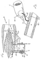
- Figure 1 shows an example of an aircraft structure, the outer skin of which contains suction surfaces in critical flow areas, namely an aircraft wing 4 that is provided with suction surfaces 41, 42.
- An engine 1 is mounted on the aircraft wing 4 by means of a suitable engine suspension 12.
- a suction line 23 for drawing off the boundary layer through the suction surfaces 41, 42 leads from the wing 4 to a region of the engine 1 that is identified by the reference symbol Z.
- a suction arrangement according to the invention for drawing off boundary layers is provided in this region Z. It should be noted that the aforementioned suction surfaces may also be provided for drawing of boundary layers on the engine fairing.
- FIG. 2 shows a schematic section through the region Z of the aircraft engine.
- the aircraft engine is identified as a whole by the reference symbol 1.
- This engine consists of a so-called bypass engine with a main flow H that is divided into a core flow K and a bypass flow M downstream of a so-called front fan.
- the core flow K flows to the engine outlet via the high-pressure compressor 11 and a high-pressure turbine.
- a high-pressure region in the vicinity of the high-pressure compressor 11 is identified by the reference symbol P.
- a branch line 10 for withdrawing high-pressure bleed air is connected to the engine 1 in this region.
- the branch line 10 leads to a turbo-supercharger assembly 2.
- the turbo-supercharger assembly is realized in the form of a single-shaft machine with a turbine 20 and a compressor (turbo pump) 24.
- the bleed air withdrawn from the high-pressure compressor 11 drives the turbine 20 and is then returned into the main flow H of the engine 1 via an exhaust line 21.
- the compressor 24 of the turbo-supercharger assembly 2 that is driven by the turbine 20 conveys the air from the suction line 23 into the main flow H of the engine 1 via a pressure line 25, wherein the pressure line 25 opens into the main flow H of the engine at a point of low static pressure U.
- turbo-supercharger assembly 2 instead of utilizing one heavy-duty turbo-supercharger assembly 2, it would also be conceivable to provide several smaller turbo-supercharger assemblies that can be easier accommodated. Such smaller supercharger assemblies are identified by the reference symbols 2a and 2b and drawn with broken lines in Figure 2 . The advantage of utilizing smaller turbo-supercharger assemblies is that they can be better accommodated in the engine suspension 12 or the engine fairing as shown in Figure 2 .
Landscapes
- Engineering & Computer Science (AREA)
- Chemical & Material Sciences (AREA)
- Combustion & Propulsion (AREA)
- Mechanical Engineering (AREA)
- General Engineering & Computer Science (AREA)
- Aviation & Aerospace Engineering (AREA)
- Fluid Mechanics (AREA)
- Physics & Mathematics (AREA)
- Supercharger (AREA)
- Structures Of Non-Positive Displacement Pumps (AREA)
- Jet Pumps And Other Pumps (AREA)
- Fats And Perfumes (AREA)
- Medicines Containing Material From Animals Or Micro-Organisms (AREA)
Abstract
Description
- The invention pertains to a suction arrangement for drawing off boundary layers on an aircraft with a structure, the outer skin of which contains suction surfaces in critical flow areas, and with at least one air breathing engine, from which the suction power required for drawing off the boundary layer is obtained.
- A suction arrangement of the above-described type is known from
DE 198 20 097 C2 . In this known arrangement, the suction power for drawing off the boundary layer is generated by a jet pump arranged in the main flow of the engine. This suction arrangement provides the advantages that no moving parts are required in order to generate the suction power for drawing off the boundary layer, and that the arrangement consequently is highly insusceptible to defects. However, one significant disadvantage of this known suction arrangement can be seen in the fact that a substantial power loss occurs due to the placement of the jet pump in the main flow of the engine. This power loss also cannot be completely prevented when the suction arrangement is not needed. - Another suction arrangement is known from
EP-A-517 459 - It is an objective of the present invention to develop a suction arrangement for drawing off boundary layers that makes it possible to achieve a highly efficient power conversion and to prevent power losses in operating states, in which the suction arrangement is not needed.
- In a suction arrangement for drawing off boundary layers according to the preamble of claim 1, this objective is attained, according to the invention, in that bleed air is withdrawn from the high-pressure region of the engine by means of a branch line and used for driving the turbine of a turbo-supercharger assembly, the compressor (also referred to as turbo pump) of which serves as the suction source for drawing off the boundary layer.
- The suction arrangement according to the invention makes it possible to attain the aforementioned objective because a turbo-supercharger assembly ensures a highly efficient power conversion and the connection of a branch line for withdrawing the bleed air from the engine can be realized in such a way that no power loss occurs in the engine when the branch line is shut off.
- In a bypass engine with a core flow and a bypass flow, it is advantageous to withdraw the bleed air in the region of the high-pressure compressor because this makes it possible to obtain the maximum power possible for the turbo-supercharger assembly.
- According to the invention, the pressure line of the compressor (turbo pump) of the turbo-supercharger assembly opens into the main flow of the engine at a point of low pressure. This design contributes to maintaining the pressure differential between the suction channel system of the arrangement for drawing off boundary layers and the outlet of the pressure line, i.e., the pressure differential to be overcome by the compressor of the supercharger assembly, as low as possible such that the power generated by the compressor can be optimally utilized.
- In another preferred embodiment of the invention, several low-power supercharger assemblies are used instead of one heavy-duty turbo-supercharger assembly, wherein these supercharger assemblies are accommodated in the region of the engine suspension and/or the engine fairing. The advantage of this variation can be seen in the fact that short pressure and suction lines can be used for the turbine of the turbo-supercharger assembly such that flow losses and heat losses remain relatively low.
- It is also advantageous to realize the turbo-supercharger assembly in the form of a single-shaft machine because machines of this type according to the state of the art are available in the form of components with a simple design that can be inexpensively manufactured.
- An embodiment of the invention is described below with reference to the enclosed figures. The figures show:
- Figure 1,
- an aircraft wing with suction surfaces for drawing off the boundary layer, as well as the aircraft engine arranged underneath said wing, and
- Figure 2,
- a schematic cross section through the aircraft engine according to
Figure 1 with a suction arrangement according to the invention for drawing off boundary layers. -
Figure 1 shows an example of an aircraft structure, the outer skin of which contains suction surfaces in critical flow areas, namely an aircraft wing 4 that is provided withsuction surfaces 41, 42. An engine 1 is mounted on the aircraft wing 4 by means of a suitable engine suspension 12. Asuction line 23 for drawing off the boundary layer through thesuction surfaces 41, 42 leads from the wing 4 to a region of the engine 1 that is identified by the reference symbol Z. A suction arrangement according to the invention for drawing off boundary layers is provided in this region Z. It should be noted that the aforementioned suction surfaces may also be provided for drawing of boundary layers on the engine fairing. -
Figure 2 shows a schematic section through the region Z of the aircraft engine. The aircraft engine is identified as a whole by the reference symbol 1. This engine consists of a so-called bypass engine with a main flow H that is divided into a core flow K and a bypass flow M downstream of a so-called front fan. The core flow K flows to the engine outlet via the high-pressure compressor 11 and a high-pressure turbine. A high-pressure region in the vicinity of the high-pressure compressor 11 is identified by the reference symbol P. A branch line 10 for withdrawing high-pressure bleed air is connected to the engine 1 in this region. The branch line 10 leads to a turbo-supercharger assembly 2. The turbo-supercharger assembly is realized in the form of a single-shaft machine with a turbine 20 and a compressor (turbo pump) 24. The bleed air withdrawn from the high-pressure compressor 11 drives the turbine 20 and is then returned into the main flow H of the engine 1 via an exhaust line 21. Thecompressor 24 of the turbo-supercharger assembly 2 that is driven by the turbine 20 conveys the air from thesuction line 23 into the main flow H of the engine 1 via apressure line 25, wherein thepressure line 25 opens into the main flow H of the engine at a point of low static pressure U. - Instead of utilizing one heavy-duty turbo-
supercharger assembly 2, it would also be conceivable to provide several smaller turbo-supercharger assemblies that can be easier accommodated. Such smaller supercharger assemblies are identified by the reference symbols 2a and 2b and drawn with broken lines inFigure 2 . The advantage of utilizing smaller turbo-supercharger assemblies is that they can be better accommodated in the engine suspension 12 or the engine fairing as shown inFigure 2 . - It should be noted that the term "comprising" does not exclude other elements or steps and the "a" or "an" does not exclude a plurality. Also elements described in association with different embodiments may be combined.
- It should also be noted that reference signs in the claims shall not be construed as limiting the scope of the claims.
-
- 1
- Aircraft engine
- 2
- Turbo-supercharger assembly
- 2a
- Low-power turbo-supercharger assemblies
- 2b
- Low-power turbo-supercharger assemblies
- 4
- Wing
- 41
- Suction surface of 4
- 42
- Suction surface of 4
- 10
- Branch line
- 11
- High-pressure compressor
- 12
- Engine suspension
- 20
- Turbine
- 21
- Exhaust line
- 23
- Suction line
- 24
- Compressor (turbo pump)
- 25
- Pressure line of 24
- H
- Main flow
- K
- Core flow
- M
- Bypass flow
- P
- High-pressure region
- U
- Low-pressure region
- Z
- Region of 1 with the suction arrangement for drawing off boundary layers
Claims (3)
- A suction arrangement for drawing off boundary layers on an aircraft with a structure, the outer skin of which contains suction surfaces in critical flow areas; wherein the suction arrangement comprises:at least one air breathing bypass engine (1) with a core flow (K), a bypass flow (M) and a main flow (H), from which bypass engine (1) the suction power required for drawing off the boundary layer is obtained,a high-pressure compressor (11) with a high-pressure region (P), which is arranged in region of the core flow (K);a branch line (10);a turbo-supercharger assembly (2) with a turbine (20) and a turbo pump compressor (24);wherein the branch line (10) is adapted for withdrawing the bleed air in the region of the high-pressure compressor (11) in the bypass engine andwherein the branch line (10) is adapted for driving the turbine (20) of the turbo-supercharger assembly (2) by the bleed air,wherein the turbo pump compressor (24) is adapted for serving as suction source for drawing off the boundary layer; characterised in that a pressure line (25) of the compressor (24) of the turbo-supercharger assembly (2) opens into the main flow (H) of the bypass engine (1) at a location of low static pressure (U).
- The suction arrangement for drawing off boundary layers of claim 1,
wherein several smaller turbo-supercharger assemblies (2a, 2b) are utilized instead of one heavy-duty turbo-supercharger assembly and accommodated in the region of the engine suspension (12) and/or the engine fairing. - The suction arrangement for drawing off boundary layers of claims 1 - 2,
wherein the turbo-supercharger assembly(s) (2, 2a, 2b) is (are) realized in the form of (a) single-shaft machine(s).
Applications Claiming Priority (3)
| Application Number | Priority Date | Filing Date | Title |
|---|---|---|---|
| DE102004024016A DE102004024016A1 (en) | 2004-05-13 | 2004-05-13 | Air suction arrangement for aircraft, has branch line to draw bleed air from high-pressure region of engine so as to drive turbine of turbo-supercharger |
| US60664904P | 2004-09-02 | 2004-09-02 | |
| PCT/EP2005/005098 WO2005113335A1 (en) | 2004-05-13 | 2005-05-11 | Boundary layer suction arrangement |
Publications (2)
| Publication Number | Publication Date |
|---|---|
| EP1744953A1 EP1744953A1 (en) | 2007-01-24 |
| EP1744953B1 true EP1744953B1 (en) | 2010-09-22 |
Family
ID=35432964
Family Applications (1)
| Application Number | Title | Priority Date | Filing Date |
|---|---|---|---|
| EP05748034A Expired - Lifetime EP1744953B1 (en) | 2004-05-13 | 2005-05-11 | Boundary layer suction arrangement |
Country Status (10)
| Country | Link |
|---|---|
| US (1) | US7837155B2 (en) |
| EP (1) | EP1744953B1 (en) |
| JP (1) | JP4786647B2 (en) |
| CN (1) | CN1950255B (en) |
| AT (1) | ATE482140T1 (en) |
| BR (1) | BRPI0510727A (en) |
| CA (1) | CA2565011C (en) |
| DE (2) | DE102004024016A1 (en) |
| RU (1) | RU2384466C2 (en) |
| WO (1) | WO2005113335A1 (en) |
Families Citing this family (7)
| Publication number | Priority date | Publication date | Assignee | Title |
|---|---|---|---|---|
| US8480350B2 (en) | 2006-10-12 | 2013-07-09 | United Technologies Corporation | Turbofan engine with variable bypass nozzle exit area and method of operation |
| DE102009043489A1 (en) | 2009-09-30 | 2011-03-31 | Airbus Operations Gmbh | Device for boundary layer extraction and composite component therefor |
| US9630706B2 (en) * | 2013-02-22 | 2017-04-25 | Rolls-Royce Corporation | Positionable ejector member for ejector enhanced boundary layer alleviation |
| RU2534480C1 (en) * | 2013-06-26 | 2014-11-27 | Виктор Семенович Савченков | Method of increase of aircraft wing lift |
| US9789954B2 (en) * | 2014-04-25 | 2017-10-17 | Rohr, Inc. | Method of controlling boundary layer flow |
| CN109367796B (en) * | 2018-09-17 | 2022-03-15 | 江西洪都航空工业集团有限责任公司 | Embedded air inlet boundary layer control device based on fluid oscillator |
| CN110374747A (en) * | 2019-07-25 | 2019-10-25 | 中国航发沈阳发动机研究所 | A kind of aircraft engine bleed air line with self-compensating function |
Family Cites Families (13)
| Publication number | Priority date | Publication date | Assignee | Title |
|---|---|---|---|---|
| US2833492A (en) * | 1955-02-07 | 1958-05-06 | Harlan D Fowler | Boundary layer control system with aerodynamic glove |
| GB1443333A (en) * | 1972-08-12 | 1976-07-21 | Mtu Muenchen Gmbh | Aircraft having apparatus for augmenting the lift of the aircraft |
| DE3412101A1 (en) | 1984-03-31 | 1985-10-10 | Deutsche Airbus GmbH, 8000 München | INSTALLATION ARRANGEMENT OF AN AUXILIARY POWER PLANT IN THE FUSELAGE OF TRANSPORT AIRCRAFT FOR THE ECONOMIC GENERATION OF AIR CONDITIONING AND OF PUSHING IN FLIGHT |
| US5114103A (en) | 1990-08-27 | 1992-05-19 | General Electric Company | Aircraft engine electrically powered boundary layer bleed system |
| RU2028963C1 (en) | 1990-10-02 | 1995-02-20 | Гришин Александр Николаевич | Flying vehicle with laminar-flow control system |
| US5137230A (en) * | 1991-06-04 | 1992-08-11 | General Electric Company | Aircraft gas turbine engine bleed air energy recovery apparatus |
| RU2084377C1 (en) * | 1992-11-02 | 1997-07-20 | Александр Николаевич Гришин | Power plant of flying vehicle with laminar-flow control system of aerodynamic surfaces |
| GB9400555D0 (en) * | 1994-01-13 | 1994-03-09 | Short Brothers Plc | Boundery layer control in aerodynamic low drag structures |
| US5779196A (en) * | 1995-12-08 | 1998-07-14 | The Boeing Company | Ram air drive laminar flow control system |
| DE19617952C2 (en) | 1996-05-04 | 1998-07-02 | Daimler Benz Aerospace Airbus | Suction generator system of an aircraft for the laminar maintenance of the boundary layer |
| DE19643069C2 (en) * | 1996-10-18 | 1999-03-25 | Daimler Benz Aerospace Airbus | Vertical tail structure for an aircraft |
| DE19820097C2 (en) * | 1998-05-06 | 2003-02-13 | Airbus Gmbh | Arrangement for boundary layer suction and impact boundary layer control for an aircraft |
| US6189324B1 (en) | 1999-10-05 | 2001-02-20 | Samuel B. Williams | Environment control unit for turbine engine |
-
2004
- 2004-05-13 DE DE102004024016A patent/DE102004024016A1/en not_active Withdrawn
-
2005
- 2005-05-11 JP JP2007512088A patent/JP4786647B2/en not_active Expired - Fee Related
- 2005-05-11 RU RU2006143163/11A patent/RU2384466C2/en not_active IP Right Cessation
- 2005-05-11 DE DE602005023724T patent/DE602005023724D1/en not_active Expired - Lifetime
- 2005-05-11 AT AT05748034T patent/ATE482140T1/en not_active IP Right Cessation
- 2005-05-11 CA CA2565011A patent/CA2565011C/en not_active Expired - Fee Related
- 2005-05-11 WO PCT/EP2005/005098 patent/WO2005113335A1/en not_active Ceased
- 2005-05-11 BR BRPI0510727-0A patent/BRPI0510727A/en not_active IP Right Cessation
- 2005-05-11 CN CN2005800147984A patent/CN1950255B/en not_active Expired - Fee Related
- 2005-05-11 US US11/568,880 patent/US7837155B2/en not_active Expired - Lifetime
- 2005-05-11 EP EP05748034A patent/EP1744953B1/en not_active Expired - Lifetime
Also Published As
| Publication number | Publication date |
|---|---|
| DE102004024016A1 (en) | 2005-12-22 |
| RU2006143163A (en) | 2008-06-20 |
| US20070266707A1 (en) | 2007-11-22 |
| EP1744953A1 (en) | 2007-01-24 |
| BRPI0510727A (en) | 2007-11-20 |
| CA2565011A1 (en) | 2005-12-01 |
| CA2565011C (en) | 2013-04-16 |
| CN1950255A (en) | 2007-04-18 |
| US7837155B2 (en) | 2010-11-23 |
| RU2384466C2 (en) | 2010-03-20 |
| DE602005023724D1 (en) | 2010-11-04 |
| JP2007537085A (en) | 2007-12-20 |
| ATE482140T1 (en) | 2010-10-15 |
| JP4786647B2 (en) | 2011-10-05 |
| CN1950255B (en) | 2011-05-18 |
| WO2005113335A1 (en) | 2005-12-01 |
Similar Documents
| Publication | Publication Date | Title |
|---|---|---|
| CN110753783B (en) | Oil cooling system for gas turbine engine | |
| US11384690B2 (en) | System and method of reducing post-shutdown engine temperatures | |
| EP2900965B1 (en) | Gas turbine engine thermal management system for heat exchanger using bypass flow | |
| EP3321490B1 (en) | Turbo-generator based bleed air system | |
| EP2053206A2 (en) | Gas turbine oil scavenging system | |
| EP3179033B1 (en) | Gas turbine rotor blade cooling assembly | |
| EP1421257B1 (en) | Double flow compressor | |
| EP2929164B1 (en) | Gas turbine engine with a low speed spool driven pump arrangement | |
| JP2013506082A (en) | Convertible fan engine with 2-block compressor | |
| JP2013506081A (en) | Convertible fan engine | |
| US20050229602A1 (en) | Forced air cooling system | |
| US11773778B1 (en) | Air bottoming cycle air cycle system source | |
| US20140090388A1 (en) | Off-take power ratio | |
| EP3260686B1 (en) | Engine bleed air and compressor surge management and corresponding method | |
| CA2565011C (en) | Boundary layer suction arrangement | |
| EP3885557B1 (en) | Integrated environmental control and buffer air system | |
| US10697301B2 (en) | Turbine engine airfoil having a cooling circuit | |
| US11085312B2 (en) | Aircraft incorporating a thrust recovery system using cabin air | |
| EP3321491B1 (en) | Electrically boosted regenerative bleed air system | |
| CN213928558U (en) | Gas turbine and compressor casing gas-entraining structure thereof |
Legal Events
| Date | Code | Title | Description |
|---|---|---|---|
| PUAI | Public reference made under article 153(3) epc to a published international application that has entered the european phase |
Free format text: ORIGINAL CODE: 0009012 |
|
| 17P | Request for examination filed |
Effective date: 20061110 |
|
| AK | Designated contracting states |
Kind code of ref document: A1 Designated state(s): AT BE BG CH CY CZ DE DK EE ES FI FR GB GR HU IE IS IT LI LT LU MC NL PL PT RO SE SI SK TR |
|
| 17Q | First examination report despatched |
Effective date: 20070228 |
|
| DAX | Request for extension of the european patent (deleted) | ||
| GRAP | Despatch of communication of intention to grant a patent |
Free format text: ORIGINAL CODE: EPIDOSNIGR1 |
|
| GRAS | Grant fee paid |
Free format text: ORIGINAL CODE: EPIDOSNIGR3 |
|
| GRAA | (expected) grant |
Free format text: ORIGINAL CODE: 0009210 |
|
| RAP1 | Party data changed (applicant data changed or rights of an application transferred) |
Owner name: AIRBUS OPERATIONS GMBH |
|
| AK | Designated contracting states |
Kind code of ref document: B1 Designated state(s): AT BE BG CH CY CZ DE DK EE ES FI FR GB GR HU IE IS IT LI LT LU MC NL PL PT RO SE SI SK TR |
|
| REG | Reference to a national code |
Ref country code: GB Ref legal event code: FG4D |
|
| REG | Reference to a national code |
Ref country code: CH Ref legal event code: EP |
|
| REG | Reference to a national code |
Ref country code: IE Ref legal event code: FG4D |
|
| REF | Corresponds to: |
Ref document number: 602005023724 Country of ref document: DE Date of ref document: 20101104 Kind code of ref document: P |
|
| PG25 | Lapsed in a contracting state [announced via postgrant information from national office to epo] |
Ref country code: LT Free format text: LAPSE BECAUSE OF FAILURE TO SUBMIT A TRANSLATION OF THE DESCRIPTION OR TO PAY THE FEE WITHIN THE PRESCRIBED TIME-LIMIT Effective date: 20100922 Ref country code: AT Free format text: LAPSE BECAUSE OF FAILURE TO SUBMIT A TRANSLATION OF THE DESCRIPTION OR TO PAY THE FEE WITHIN THE PRESCRIBED TIME-LIMIT Effective date: 20100922 Ref country code: FI Free format text: LAPSE BECAUSE OF FAILURE TO SUBMIT A TRANSLATION OF THE DESCRIPTION OR TO PAY THE FEE WITHIN THE PRESCRIBED TIME-LIMIT Effective date: 20100922 |
|
| REG | Reference to a national code |
Ref country code: NL Ref legal event code: VDEP Effective date: 20100922 |
|
| LTIE | Lt: invalidation of european patent or patent extension |
Effective date: 20100922 |
|
| PG25 | Lapsed in a contracting state [announced via postgrant information from national office to epo] |
Ref country code: SI Free format text: LAPSE BECAUSE OF FAILURE TO SUBMIT A TRANSLATION OF THE DESCRIPTION OR TO PAY THE FEE WITHIN THE PRESCRIBED TIME-LIMIT Effective date: 20100922 Ref country code: PL Free format text: LAPSE BECAUSE OF FAILURE TO SUBMIT A TRANSLATION OF THE DESCRIPTION OR TO PAY THE FEE WITHIN THE PRESCRIBED TIME-LIMIT Effective date: 20100922 |
|
| PG25 | Lapsed in a contracting state [announced via postgrant information from national office to epo] |
Ref country code: SE Free format text: LAPSE BECAUSE OF FAILURE TO SUBMIT A TRANSLATION OF THE DESCRIPTION OR TO PAY THE FEE WITHIN THE PRESCRIBED TIME-LIMIT Effective date: 20100922 Ref country code: GR Free format text: LAPSE BECAUSE OF FAILURE TO SUBMIT A TRANSLATION OF THE DESCRIPTION OR TO PAY THE FEE WITHIN THE PRESCRIBED TIME-LIMIT Effective date: 20101223 |
|
| PG25 | Lapsed in a contracting state [announced via postgrant information from national office to epo] |
Ref country code: NL Free format text: LAPSE BECAUSE OF FAILURE TO SUBMIT A TRANSLATION OF THE DESCRIPTION OR TO PAY THE FEE WITHIN THE PRESCRIBED TIME-LIMIT Effective date: 20100922 Ref country code: RO Free format text: LAPSE BECAUSE OF FAILURE TO SUBMIT A TRANSLATION OF THE DESCRIPTION OR TO PAY THE FEE WITHIN THE PRESCRIBED TIME-LIMIT Effective date: 20100922 Ref country code: CZ Free format text: LAPSE BECAUSE OF FAILURE TO SUBMIT A TRANSLATION OF THE DESCRIPTION OR TO PAY THE FEE WITHIN THE PRESCRIBED TIME-LIMIT Effective date: 20100922 Ref country code: PT Free format text: LAPSE BECAUSE OF FAILURE TO SUBMIT A TRANSLATION OF THE DESCRIPTION OR TO PAY THE FEE WITHIN THE PRESCRIBED TIME-LIMIT Effective date: 20110124 Ref country code: IS Free format text: LAPSE BECAUSE OF FAILURE TO SUBMIT A TRANSLATION OF THE DESCRIPTION OR TO PAY THE FEE WITHIN THE PRESCRIBED TIME-LIMIT Effective date: 20110122 Ref country code: EE Free format text: LAPSE BECAUSE OF FAILURE TO SUBMIT A TRANSLATION OF THE DESCRIPTION OR TO PAY THE FEE WITHIN THE PRESCRIBED TIME-LIMIT Effective date: 20100922 Ref country code: SK Free format text: LAPSE BECAUSE OF FAILURE TO SUBMIT A TRANSLATION OF THE DESCRIPTION OR TO PAY THE FEE WITHIN THE PRESCRIBED TIME-LIMIT Effective date: 20100922 |
|
| PG25 | Lapsed in a contracting state [announced via postgrant information from national office to epo] |
Ref country code: BE Free format text: LAPSE BECAUSE OF FAILURE TO SUBMIT A TRANSLATION OF THE DESCRIPTION OR TO PAY THE FEE WITHIN THE PRESCRIBED TIME-LIMIT Effective date: 20100922 |
|
| PG25 | Lapsed in a contracting state [announced via postgrant information from national office to epo] |
Ref country code: ES Free format text: LAPSE BECAUSE OF FAILURE TO SUBMIT A TRANSLATION OF THE DESCRIPTION OR TO PAY THE FEE WITHIN THE PRESCRIBED TIME-LIMIT Effective date: 20110102 |
|
| PLBE | No opposition filed within time limit |
Free format text: ORIGINAL CODE: 0009261 |
|
| STAA | Information on the status of an ep patent application or granted ep patent |
Free format text: STATUS: NO OPPOSITION FILED WITHIN TIME LIMIT |
|
| 26N | No opposition filed |
Effective date: 20110623 |
|
| PG25 | Lapsed in a contracting state [announced via postgrant information from national office to epo] |
Ref country code: DK Free format text: LAPSE BECAUSE OF FAILURE TO SUBMIT A TRANSLATION OF THE DESCRIPTION OR TO PAY THE FEE WITHIN THE PRESCRIBED TIME-LIMIT Effective date: 20100922 |
|
| REG | Reference to a national code |
Ref country code: DE Ref legal event code: R097 Ref document number: 602005023724 Country of ref document: DE Effective date: 20110623 |
|
| PG25 | Lapsed in a contracting state [announced via postgrant information from national office to epo] |
Ref country code: MC Free format text: LAPSE BECAUSE OF NON-PAYMENT OF DUE FEES Effective date: 20110531 |
|
| REG | Reference to a national code |
Ref country code: CH Ref legal event code: PL |
|
| PG25 | Lapsed in a contracting state [announced via postgrant information from national office to epo] |
Ref country code: CH Free format text: LAPSE BECAUSE OF NON-PAYMENT OF DUE FEES Effective date: 20110531 Ref country code: LI Free format text: LAPSE BECAUSE OF NON-PAYMENT OF DUE FEES Effective date: 20110531 |
|
| REG | Reference to a national code |
Ref country code: IE Ref legal event code: MM4A |
|
| PG25 | Lapsed in a contracting state [announced via postgrant information from national office to epo] |
Ref country code: IE Free format text: LAPSE BECAUSE OF NON-PAYMENT OF DUE FEES Effective date: 20110511 |
|
| PG25 | Lapsed in a contracting state [announced via postgrant information from national office to epo] |
Ref country code: LU Free format text: LAPSE BECAUSE OF NON-PAYMENT OF DUE FEES Effective date: 20110511 Ref country code: CY Free format text: LAPSE BECAUSE OF FAILURE TO SUBMIT A TRANSLATION OF THE DESCRIPTION OR TO PAY THE FEE WITHIN THE PRESCRIBED TIME-LIMIT Effective date: 20100922 |
|
| PG25 | Lapsed in a contracting state [announced via postgrant information from national office to epo] |
Ref country code: TR Free format text: LAPSE BECAUSE OF FAILURE TO SUBMIT A TRANSLATION OF THE DESCRIPTION OR TO PAY THE FEE WITHIN THE PRESCRIBED TIME-LIMIT Effective date: 20100922 Ref country code: BG Free format text: LAPSE BECAUSE OF FAILURE TO SUBMIT A TRANSLATION OF THE DESCRIPTION OR TO PAY THE FEE WITHIN THE PRESCRIBED TIME-LIMIT Effective date: 20101222 |
|
| PG25 | Lapsed in a contracting state [announced via postgrant information from national office to epo] |
Ref country code: HU Free format text: LAPSE BECAUSE OF FAILURE TO SUBMIT A TRANSLATION OF THE DESCRIPTION OR TO PAY THE FEE WITHIN THE PRESCRIBED TIME-LIMIT Effective date: 20100922 |
|
| REG | Reference to a national code |
Ref country code: DE Ref legal event code: R082 Ref document number: 602005023724 Country of ref document: DE Representative=s name: LKGLOBAL | LORENZ & KOPF PARTG MBB PATENTANWAE, DE Ref country code: DE Ref legal event code: R082 Ref document number: 602005023724 Country of ref document: DE Representative=s name: KOPF WESTENBERGER WACHENHAUSEN PATENTANWAELTE , DE |
|
| REG | Reference to a national code |
Ref country code: FR Ref legal event code: PLFP Year of fee payment: 12 |
|
| PGFP | Annual fee paid to national office [announced via postgrant information from national office to epo] |
Ref country code: IT Payment date: 20160524 Year of fee payment: 12 |
|
| REG | Reference to a national code |
Ref country code: FR Ref legal event code: PLFP Year of fee payment: 13 |
|
| REG | Reference to a national code |
Ref country code: FR Ref legal event code: PLFP Year of fee payment: 14 |
|
| PG25 | Lapsed in a contracting state [announced via postgrant information from national office to epo] |
Ref country code: IT Free format text: LAPSE BECAUSE OF NON-PAYMENT OF DUE FEES Effective date: 20170511 |
|
| PGFP | Annual fee paid to national office [announced via postgrant information from national office to epo] |
Ref country code: DE Payment date: 20190521 Year of fee payment: 15 |
|
| PGFP | Annual fee paid to national office [announced via postgrant information from national office to epo] |
Ref country code: FR Payment date: 20190523 Year of fee payment: 15 |
|
| PGFP | Annual fee paid to national office [announced via postgrant information from national office to epo] |
Ref country code: GB Payment date: 20190521 Year of fee payment: 15 |
|
| REG | Reference to a national code |
Ref country code: DE Ref legal event code: R119 Ref document number: 602005023724 Country of ref document: DE |
|
| GBPC | Gb: european patent ceased through non-payment of renewal fee |
Effective date: 20200511 |
|
| PG25 | Lapsed in a contracting state [announced via postgrant information from national office to epo] |
Ref country code: FR Free format text: LAPSE BECAUSE OF NON-PAYMENT OF DUE FEES Effective date: 20200531 Ref country code: GB Free format text: LAPSE BECAUSE OF NON-PAYMENT OF DUE FEES Effective date: 20200511 |
|
| PG25 | Lapsed in a contracting state [announced via postgrant information from national office to epo] |
Ref country code: DE Free format text: LAPSE BECAUSE OF NON-PAYMENT OF DUE FEES Effective date: 20201201 |