EP1744705B1 - Endoluminal prosthesis - Google Patents
Endoluminal prosthesis Download PDFInfo
- Publication number
- EP1744705B1 EP1744705B1 EP04731261A EP04731261A EP1744705B1 EP 1744705 B1 EP1744705 B1 EP 1744705B1 EP 04731261 A EP04731261 A EP 04731261A EP 04731261 A EP04731261 A EP 04731261A EP 1744705 B1 EP1744705 B1 EP 1744705B1
- Authority
- EP
- European Patent Office
- Prior art keywords
- serpentine
- endoluminal prosthesis
- frame
- prosthesis according
- serpentines
- Prior art date
- Legal status (The legal status is an assumption and is not a legal conclusion. Google has not performed a legal analysis and makes no representation as to the accuracy of the status listed.)
- Not-in-force
Links
Images


Classifications
-
- A—HUMAN NECESSITIES
- A61—MEDICAL OR VETERINARY SCIENCE; HYGIENE
- A61F—FILTERS IMPLANTABLE INTO BLOOD VESSELS; PROSTHESES; DEVICES PROVIDING PATENCY TO, OR PREVENTING COLLAPSING OF, TUBULAR STRUCTURES OF THE BODY, e.g. STENTS; ORTHOPAEDIC, NURSING OR CONTRACEPTIVE DEVICES; FOMENTATION; TREATMENT OR PROTECTION OF EYES OR EARS; BANDAGES, DRESSINGS OR ABSORBENT PADS; FIRST-AID KITS
- A61F2/00—Filters implantable into blood vessels; Prostheses, i.e. artificial substitutes or replacements for parts of the body; Appliances for connecting them with the body; Devices providing patency to, or preventing collapsing of, tubular structures of the body, e.g. stents
- A61F2/82—Devices providing patency to, or preventing collapsing of, tubular structures of the body, e.g. stents
- A61F2/86—Stents in a form characterised by the wire-like elements; Stents in the form characterised by a net-like or mesh-like structure
- A61F2/90—Stents in a form characterised by the wire-like elements; Stents in the form characterised by a net-like or mesh-like structure characterised by a net-like or mesh-like structure
- A61F2/91—Stents in a form characterised by the wire-like elements; Stents in the form characterised by a net-like or mesh-like structure characterised by a net-like or mesh-like structure made from perforated sheet material or tubes, e.g. perforated by laser cuts or etched holes
- A61F2/915—Stents in a form characterised by the wire-like elements; Stents in the form characterised by a net-like or mesh-like structure characterised by a net-like or mesh-like structure made from perforated sheet material or tubes, e.g. perforated by laser cuts or etched holes with bands having a meander structure, adjacent bands being connected to each other
-
- A—HUMAN NECESSITIES
- A61—MEDICAL OR VETERINARY SCIENCE; HYGIENE
- A61F—FILTERS IMPLANTABLE INTO BLOOD VESSELS; PROSTHESES; DEVICES PROVIDING PATENCY TO, OR PREVENTING COLLAPSING OF, TUBULAR STRUCTURES OF THE BODY, e.g. STENTS; ORTHOPAEDIC, NURSING OR CONTRACEPTIVE DEVICES; FOMENTATION; TREATMENT OR PROTECTION OF EYES OR EARS; BANDAGES, DRESSINGS OR ABSORBENT PADS; FIRST-AID KITS
- A61F2/00—Filters implantable into blood vessels; Prostheses, i.e. artificial substitutes or replacements for parts of the body; Appliances for connecting them with the body; Devices providing patency to, or preventing collapsing of, tubular structures of the body, e.g. stents
- A61F2/82—Devices providing patency to, or preventing collapsing of, tubular structures of the body, e.g. stents
- A61F2/86—Stents in a form characterised by the wire-like elements; Stents in the form characterised by a net-like or mesh-like structure
- A61F2/90—Stents in a form characterised by the wire-like elements; Stents in the form characterised by a net-like or mesh-like structure characterised by a net-like or mesh-like structure
- A61F2/91—Stents in a form characterised by the wire-like elements; Stents in the form characterised by a net-like or mesh-like structure characterised by a net-like or mesh-like structure made from perforated sheet material or tubes, e.g. perforated by laser cuts or etched holes
- A61F2/915—Stents in a form characterised by the wire-like elements; Stents in the form characterised by a net-like or mesh-like structure characterised by a net-like or mesh-like structure made from perforated sheet material or tubes, e.g. perforated by laser cuts or etched holes with bands having a meander structure, adjacent bands being connected to each other
- A61F2002/91508—Stents in a form characterised by the wire-like elements; Stents in the form characterised by a net-like or mesh-like structure characterised by a net-like or mesh-like structure made from perforated sheet material or tubes, e.g. perforated by laser cuts or etched holes with bands having a meander structure, adjacent bands being connected to each other the meander having a difference in amplitude along the band
-
- A—HUMAN NECESSITIES
- A61—MEDICAL OR VETERINARY SCIENCE; HYGIENE
- A61F—FILTERS IMPLANTABLE INTO BLOOD VESSELS; PROSTHESES; DEVICES PROVIDING PATENCY TO, OR PREVENTING COLLAPSING OF, TUBULAR STRUCTURES OF THE BODY, e.g. STENTS; ORTHOPAEDIC, NURSING OR CONTRACEPTIVE DEVICES; FOMENTATION; TREATMENT OR PROTECTION OF EYES OR EARS; BANDAGES, DRESSINGS OR ABSORBENT PADS; FIRST-AID KITS
- A61F2/00—Filters implantable into blood vessels; Prostheses, i.e. artificial substitutes or replacements for parts of the body; Appliances for connecting them with the body; Devices providing patency to, or preventing collapsing of, tubular structures of the body, e.g. stents
- A61F2/82—Devices providing patency to, or preventing collapsing of, tubular structures of the body, e.g. stents
- A61F2/86—Stents in a form characterised by the wire-like elements; Stents in the form characterised by a net-like or mesh-like structure
- A61F2/90—Stents in a form characterised by the wire-like elements; Stents in the form characterised by a net-like or mesh-like structure characterised by a net-like or mesh-like structure
- A61F2/91—Stents in a form characterised by the wire-like elements; Stents in the form characterised by a net-like or mesh-like structure characterised by a net-like or mesh-like structure made from perforated sheet material or tubes, e.g. perforated by laser cuts or etched holes
- A61F2/915—Stents in a form characterised by the wire-like elements; Stents in the form characterised by a net-like or mesh-like structure characterised by a net-like or mesh-like structure made from perforated sheet material or tubes, e.g. perforated by laser cuts or etched holes with bands having a meander structure, adjacent bands being connected to each other
- A61F2002/91516—Stents in a form characterised by the wire-like elements; Stents in the form characterised by a net-like or mesh-like structure characterised by a net-like or mesh-like structure made from perforated sheet material or tubes, e.g. perforated by laser cuts or etched holes with bands having a meander structure, adjacent bands being connected to each other the meander having a change in frequency along the band
-
- A—HUMAN NECESSITIES
- A61—MEDICAL OR VETERINARY SCIENCE; HYGIENE
- A61F—FILTERS IMPLANTABLE INTO BLOOD VESSELS; PROSTHESES; DEVICES PROVIDING PATENCY TO, OR PREVENTING COLLAPSING OF, TUBULAR STRUCTURES OF THE BODY, e.g. STENTS; ORTHOPAEDIC, NURSING OR CONTRACEPTIVE DEVICES; FOMENTATION; TREATMENT OR PROTECTION OF EYES OR EARS; BANDAGES, DRESSINGS OR ABSORBENT PADS; FIRST-AID KITS
- A61F2/00—Filters implantable into blood vessels; Prostheses, i.e. artificial substitutes or replacements for parts of the body; Appliances for connecting them with the body; Devices providing patency to, or preventing collapsing of, tubular structures of the body, e.g. stents
- A61F2/82—Devices providing patency to, or preventing collapsing of, tubular structures of the body, e.g. stents
- A61F2/86—Stents in a form characterised by the wire-like elements; Stents in the form characterised by a net-like or mesh-like structure
- A61F2/90—Stents in a form characterised by the wire-like elements; Stents in the form characterised by a net-like or mesh-like structure characterised by a net-like or mesh-like structure
- A61F2/91—Stents in a form characterised by the wire-like elements; Stents in the form characterised by a net-like or mesh-like structure characterised by a net-like or mesh-like structure made from perforated sheet material or tubes, e.g. perforated by laser cuts or etched holes
- A61F2/915—Stents in a form characterised by the wire-like elements; Stents in the form characterised by a net-like or mesh-like structure characterised by a net-like or mesh-like structure made from perforated sheet material or tubes, e.g. perforated by laser cuts or etched holes with bands having a meander structure, adjacent bands being connected to each other
- A61F2002/91525—Stents in a form characterised by the wire-like elements; Stents in the form characterised by a net-like or mesh-like structure characterised by a net-like or mesh-like structure made from perforated sheet material or tubes, e.g. perforated by laser cuts or etched holes with bands having a meander structure, adjacent bands being connected to each other within the whole structure different bands showing different meander characteristics, e.g. frequency or amplitude
-
- A—HUMAN NECESSITIES
- A61—MEDICAL OR VETERINARY SCIENCE; HYGIENE
- A61F—FILTERS IMPLANTABLE INTO BLOOD VESSELS; PROSTHESES; DEVICES PROVIDING PATENCY TO, OR PREVENTING COLLAPSING OF, TUBULAR STRUCTURES OF THE BODY, e.g. STENTS; ORTHOPAEDIC, NURSING OR CONTRACEPTIVE DEVICES; FOMENTATION; TREATMENT OR PROTECTION OF EYES OR EARS; BANDAGES, DRESSINGS OR ABSORBENT PADS; FIRST-AID KITS
- A61F2/00—Filters implantable into blood vessels; Prostheses, i.e. artificial substitutes or replacements for parts of the body; Appliances for connecting them with the body; Devices providing patency to, or preventing collapsing of, tubular structures of the body, e.g. stents
- A61F2/82—Devices providing patency to, or preventing collapsing of, tubular structures of the body, e.g. stents
- A61F2/86—Stents in a form characterised by the wire-like elements; Stents in the form characterised by a net-like or mesh-like structure
- A61F2/90—Stents in a form characterised by the wire-like elements; Stents in the form characterised by a net-like or mesh-like structure characterised by a net-like or mesh-like structure
- A61F2/91—Stents in a form characterised by the wire-like elements; Stents in the form characterised by a net-like or mesh-like structure characterised by a net-like or mesh-like structure made from perforated sheet material or tubes, e.g. perforated by laser cuts or etched holes
- A61F2/915—Stents in a form characterised by the wire-like elements; Stents in the form characterised by a net-like or mesh-like structure characterised by a net-like or mesh-like structure made from perforated sheet material or tubes, e.g. perforated by laser cuts or etched holes with bands having a meander structure, adjacent bands being connected to each other
- A61F2002/91533—Stents in a form characterised by the wire-like elements; Stents in the form characterised by a net-like or mesh-like structure characterised by a net-like or mesh-like structure made from perforated sheet material or tubes, e.g. perforated by laser cuts or etched holes with bands having a meander structure, adjacent bands being connected to each other characterised by the phase between adjacent bands
- A61F2002/91541—Adjacent bands are arranged out of phase
-
- A—HUMAN NECESSITIES
- A61—MEDICAL OR VETERINARY SCIENCE; HYGIENE
- A61F—FILTERS IMPLANTABLE INTO BLOOD VESSELS; PROSTHESES; DEVICES PROVIDING PATENCY TO, OR PREVENTING COLLAPSING OF, TUBULAR STRUCTURES OF THE BODY, e.g. STENTS; ORTHOPAEDIC, NURSING OR CONTRACEPTIVE DEVICES; FOMENTATION; TREATMENT OR PROTECTION OF EYES OR EARS; BANDAGES, DRESSINGS OR ABSORBENT PADS; FIRST-AID KITS
- A61F2/00—Filters implantable into blood vessels; Prostheses, i.e. artificial substitutes or replacements for parts of the body; Appliances for connecting them with the body; Devices providing patency to, or preventing collapsing of, tubular structures of the body, e.g. stents
- A61F2/82—Devices providing patency to, or preventing collapsing of, tubular structures of the body, e.g. stents
- A61F2/86—Stents in a form characterised by the wire-like elements; Stents in the form characterised by a net-like or mesh-like structure
- A61F2/90—Stents in a form characterised by the wire-like elements; Stents in the form characterised by a net-like or mesh-like structure characterised by a net-like or mesh-like structure
- A61F2/91—Stents in a form characterised by the wire-like elements; Stents in the form characterised by a net-like or mesh-like structure characterised by a net-like or mesh-like structure made from perforated sheet material or tubes, e.g. perforated by laser cuts or etched holes
- A61F2/915—Stents in a form characterised by the wire-like elements; Stents in the form characterised by a net-like or mesh-like structure characterised by a net-like or mesh-like structure made from perforated sheet material or tubes, e.g. perforated by laser cuts or etched holes with bands having a meander structure, adjacent bands being connected to each other
- A61F2002/9155—Adjacent bands being connected to each other
- A61F2002/91558—Adjacent bands being connected to each other connected peak to peak
-
- A—HUMAN NECESSITIES
- A61—MEDICAL OR VETERINARY SCIENCE; HYGIENE
- A61F—FILTERS IMPLANTABLE INTO BLOOD VESSELS; PROSTHESES; DEVICES PROVIDING PATENCY TO, OR PREVENTING COLLAPSING OF, TUBULAR STRUCTURES OF THE BODY, e.g. STENTS; ORTHOPAEDIC, NURSING OR CONTRACEPTIVE DEVICES; FOMENTATION; TREATMENT OR PROTECTION OF EYES OR EARS; BANDAGES, DRESSINGS OR ABSORBENT PADS; FIRST-AID KITS
- A61F2230/00—Geometry of prostheses classified in groups A61F2/00 - A61F2/26 or A61F2/82 or A61F9/00 or A61F11/00 or subgroups thereof
- A61F2230/0002—Two-dimensional shapes, e.g. cross-sections
- A61F2230/0028—Shapes in the form of latin or greek characters
- A61F2230/0054—V-shaped
-
- A—HUMAN NECESSITIES
- A61—MEDICAL OR VETERINARY SCIENCE; HYGIENE
- A61F—FILTERS IMPLANTABLE INTO BLOOD VESSELS; PROSTHESES; DEVICES PROVIDING PATENCY TO, OR PREVENTING COLLAPSING OF, TUBULAR STRUCTURES OF THE BODY, e.g. STENTS; ORTHOPAEDIC, NURSING OR CONTRACEPTIVE DEVICES; FOMENTATION; TREATMENT OR PROTECTION OF EYES OR EARS; BANDAGES, DRESSINGS OR ABSORBENT PADS; FIRST-AID KITS
- A61F2250/00—Special features of prostheses classified in groups A61F2/00 - A61F2/26 or A61F2/82 or A61F9/00 or A61F11/00 or subgroups thereof
- A61F2250/0058—Additional features; Implant or prostheses properties not otherwise provided for
- A61F2250/0096—Markers and sensors for detecting a position or changes of a position of an implant, e.g. RF sensors, ultrasound markers
- A61F2250/0098—Markers and sensors for detecting a position or changes of a position of an implant, e.g. RF sensors, ultrasound markers radio-opaque, e.g. radio-opaque markers
Definitions
- the object of the present invention is an endoluminal prosthesis to be used in passages or ducts of a human body, such as to restore the passage in blood vessels narrowed or occluded by diseases such as a stenosis, in bile ducts or other similar organs of living bodies.
- the present invention also relates to such type of endoluminal prosthesis which are self-expanding, e.g. made of superelastic or shape memory materials such as Nitinol.
- the present invention also relates to an endoluminal prosthesis provided with means for a prompt location thereof, e.g. by radioscopy.
- Endoluminal prosthesis i.e. stents, particularly of the self-expanding type, are known for example by US-A-4665771 , US-A-4665905 , US-A-4925445 or EP-A-0928606 .
- US 2004/0073291 discloses a prosthesis similar to the one recited in the preamble of claim 1.
- the complex geometry of such known stents may be harmful, since it can hang up to or pinch the vessel wall, thus favouring the reforming of obstructions, such as plaques and stenosis.
- the problem at the heart of the present invention is to provide an endoluminal prosthesis, having such structural and functional characteristics to overcome the drawbacks mentioned with reference to the prior art.
- Figure 1 is a perspective view of an expanded endoluminal prosthesis portion, in accordance with a first embodiment
- Figure 2 is a plane development of a portion of the prosthesis from Figure 1 ;
- Figure 3 is a plane development of the prosthesis from Figure 1 in the collapsed state
- Figure 4a is a perspective view of a portion of the prosthesis from Figure 1 in the collapsed state
- Figure 4b is a perspective view of the collapsed prosthesis in accordance with a further embodiment
- Figure 5 illustrates a detail of the plane development of the prosthesis from Figure 1 when collapsed
- Figure 6 is a view of a detail of the prosthesis from Figure 1 when expanded;
- Figure 7 illustrates a detail of a plane development of a collapsed endoluminal prosthesis according to a further embodiment
- Figure 8 is a view of a detail of the prosthesis from Figure 7 when expanded;
- Figure 9 illustrates a detail of a plane development of a collapsed endoluminal prosthesis according to a still further embodiment
- Figure 10 is a view of a detail of the prosthesis from Figure 9 when expanded;
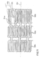
- Figure 11 illustrates a detail of a plane development of a collapsed endoluminal prosthesis according to a further embodiment
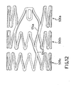
- Figure 12 is a view of a detail of the prosthesis from figure 11 , when expanded;
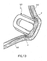
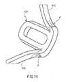
- Figures 13 and 14 are perspective views of a detail of the prosthesis from Figure 1 when expanded, wherein the stress condition and the corresponding strain condition are highlighted;
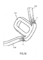
- Figures 15 and 16 are perspective views of a detail of the prosthesis from figure 7 when expanded, wherein the stress condition and the corresponding strain condition are highlighted;
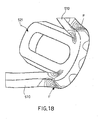
- Figures 17 and 18 are perspective views of a detail of the prosthesis from figure 9 when expanded, wherein the stress condition and the corresponding strain condition are highlighted;
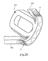
- Figures 19 and 20 are a perspective view of a detail of the prosthesis from figure 11 when expanded, wherein the stress condition and the corresponding strain condition are highlighted;
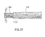
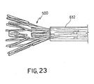
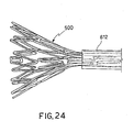
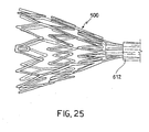
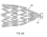
- Figures 21 to 26 are views of six expansion steps of the prosthesis from Figure 1 .
- an endoluminal prosthesis as a whole, such as a prosthesis of the self-expanding type for ducts or vessels of living bodies, such as blood vessels and bile ducts or gastro-intestinal ducts or similar.
- the endoluminal prosthesis comprises a tubular body 502 suitable to turn from a collapsed condition to an expanded or partially expanded condition.
- collapsed condition is meant a state of the prosthesis as being contracted such as to have a smaller bulk than in an operating use condition, e.g. a condition where the tubular body 502 has a smaller size or outer diameter than in an operating use condition.
- the prosthesis is arranged in a collapsed condition when it is either accommodated or arranged on a transport and delivery device suitable to travel along a duct or vessel to the area to be treated.
- a transport and delivery device suitable to travel along a duct or vessel to the area to be treated.
- this is accommodated in a sheath such as to be maintained in the collapsed condition ( Figure 4 and 21 ).
- expanded or partially expanded condition is meant a condition where the prosthesis is free from restrictions or an operating use condition with the prosthesis being widened upon pressure contact against the inner surfaces of a duct or vessel walls ( figures 1 , 6 and 26 where it is illustrated with an expanded and a partially expanded length).
- the tubular body 502 develops along a longitudinal axis 504.
- longitudinal axis is meant for example either a symmetry axis of a cylindrical body or the stretch axial direction of a tubular body.
- the tubular body 502 comprises a plurality of serpentines 506a, 506b, 506c, or closed meander paths, developing along a substantially circumpherential direction.
- serpentines are meant a zig-zag/to-and-fro developing element around a main direction of stretching. [0037]. Each of these serpentines comprising either arm portions or arms 510 of predetermined length 600 transversal to their main longitudinal stretch..
- Each of said serpentines 506a, 506b, 506c comprises either bended portions or bends 512, which join two subsequent arms 510 to form said meander path.
- At least a bridge 514a, 514b of a main longitudinal stretch connects two adjacent serpentines 506a and 506b or 506b and 506c or 506c and 506b.
- the bends 512 facing an adjacent serpentine 506b or 506c are circumferentially staggered 620 relative to the opposite bends 512 of the adjoining serpentine 506b or 506c, both when the prosthesis is collapsed and when the prosthesis is expanded or partially expanded.
- the at least one bridge 514a and 514b connecting adjacent serpentines 506a and 506b or 506b and 506c or 506c and 506b stretches substantially straight.
- the at least one bridge 514a and 514b has a length 602 transversal to its main longitudinal direction which has a greater value than the length 600 of arms 510.
- an endoluminal prosthesis 500 comprises a tubular body 502 developing along a longitudinal axis 504.
- the tubular body comprises a plurality of serpentines or meander paths 506a, 506b, 506c preferably closed, which develop according to a circumpherential direction 508 relative to the direction of the longitudinal axis of the endoluminal prosthesis.
- the circumpherential direction 508 is illustrated in Figure 4a with reference to the perspective view of the prosthesis in a closed configuration and in figure 3 and 5 with reference to the plane development of the tubular body 502 of the prosthesis in a closed configuration.
- a serpentine comprises arms 510 connected by bends 512. According to a possible embodiment, the arms are substantially straight.
- the arms are connected by bends such as to form a sequence of peaks and valleys along the circumpherential direction of the corresponding serpentines.
- bends such as to form a sequence of peaks and valleys along the circumpherential direction of the corresponding serpentines.
- peaks 516a those bends being convex towards the outside of the prosthesis will be identified as peaks 516a and those bends being concave towards the outside of the prosthesis, i.e. moving away from a middle axis 524, will be identified as valleys 516b.
- Two adjacent serpentines are connected by at least one bridge 514a, 514b thus forming at least two cells between both adjacent serpentines.
- bridge 514a, 514b With “cell” is meant a closed periphery defined by a length of a first serpentine, a first connecting bridge, a length of a second serpentine adjacent to the first one (with the path developing in the opposite way along the circumpherential direction) and a second connecting bridge immediately next to the first one.
- references 518a and 518b there have been represented two different cells and the perimeters or areas thereof have been outlined.
- the plurality of serpentines comprise a first serpentine 506a, a second serpentine 506b and a third serpentine, 506c.
- the second serpentine 506b and the third serpentine 506c repeat alternatively along the longitudinal axis.
- the second serpentine and the third serpentine are substantially identical.
- they can be arranged specularly relative to a circumpherential direction 520 intermediate between both serpentines.
- the second and third serpentines can be arranged specularly relative to a circumpherential direction 520 intermediate between both serpentines and staggered to one another along the circumpherential direction.
- said at least one bridge 514 is joined with a bend 512 of a serpentine 506a or 506b or 506c and with a bend 512 of an opposite serpentine 506b or 506c or 506a.
- the at least one bridge 514a and 514b has a substantially constant width 602 all along its longitudinal stretch.
- the at least one bridge 514a, 514b has a width 602 substantially equal to twice the width 600 of arms 510.
- the at least one bridge 514a and 514b has substantially straight edges. In other words, a bridge 514a, 514b extends without forming any bend, or folds, between a connecting or joint portion thereof to a first serpentine and a second connecting or joint portion thereof to a second serpentine.
- At least one bridge 514a, 514b is comprised between all the adjacent serpentines 506a, 506b and 506c.
- a plurality of bridges 514a, 514b is comprised between adjacent serpentines 506a and 506b or 506b and 506c or 506c and 506b.
- a bridge 514b is provided every four bends 512 as counted along the path of each serpentine.
- a bridge 514b is provided every six bends 510 as counted along the path of each serpentine.
- a bridge 514b is provided every ten bends 510 as counted along the path of each serpentine.
- the at least one bridge 514a and 514b develops according to a direction 606 tangential to the tubular body 502 and biased relative to an axis 604 parallel to the longitudinal axis 504 of said body (for example by an angle designated with the reference a or b) .
- all the bridges 514b between at least two adjacent serpentines 506b and 506c are parallel to one another.
- the prosthesis comprises a cell 518a, 518b comprising opposite lengths of two adjoining serpentines 506a and 506b or 506b and 506c or 506c and 506b comprised between two subsequent bridges 514a, 514b, and said subsequent bridges 514a and 514b forming a closed path (such as indicated by dotted line 518b in Figure 2 ).
- the arms 510 are substantially straight. In other words, an arm extends without forming any bend, or fold, between a connecting or joint portion thereof to a first bend 512 and a second connecting or joint portion thereof to a second bend 512.
- the arms 510 comprise substantially straight edges.
- At least one cell 518b comprises six complete bends 512.
- At least one cell 518b comprises ten complete bends 512.
- At least one cell 518b comprises eighteen complete bends 512.
- At least one prosthesis 500 length when being in a collapsed state, comprises a plurality of serpentines 506b and 506c equal to one another, having corresponding bends 512, facing the same end as the prosthesis 500, such as the proximal end, either circumpherentially aligned with one another, or on the same axis 610 parallel to longitudinal axis 504 of tubular body 502.
- said at least one length of prosthesis is an intermediate portion of the prosthesis or, preferably, a middle length of the prosthesis 500.
- said prosthesis 500 is a unique body.
- said body 502 is obtained by cutting a tubular element, preferably by laser cutting.
- said body is made of a superelastic material.
- said body is made of a strain hardened pseudoelastic material.
- a material being in the austenitic state at room temperature (Af ⁇ 15°C) when annealed can be used, to which is then applied a sufficient strain hardening, such as greater than 30%, which allows to get 3%-4% elastic recovery after deformation or greater.
- a sufficient strain hardening such as greater than 30%, which allows to get 3%-4% elastic recovery after deformation or greater.
- 50% strain hardening is applied.
- said body 502 is made of a shape memory material.
- said body is made of Nitinol, or a Ni and Ti based alloy, such as with Nickel nominal weight percentage of 55,8%.
- a material with Austenite-to-Martensite phase transition can be used that, when being in the annealed or stress-relieved state, during a heating of the same the higher temperature of the end of austenite transformation, or Af, is lower than 15°C.
- the first serpentine 506a comprises at least one frame 521 defining a slot or housing 522.
- the frame 521 is arranged at a bend between two arms.
- the frame 521 and the slot 522 can be arranged in place of at least two arms and one bend relative to the second or third serpentines.
- the second serpentine and the third serpentine comprise the same number of arms and the same number of bends.
- the frame 521 and the slot 522 are arranged at the bend between two arms in place of four arms and three bends relative to the second or third serpentines.
- the arms and the bends replaced by the slot have been illustrated with a dotted line.
- the frame 521 occupies the whole length left free by the replaced arms and bends, as measured along the circumpherential direction and when the endoluminal prosthesis is in the collapsed condition.
- the slot or housing 522 passes all through the thickness of the tubular body 502.
- the frame 521 is arranged in the concave part of the bend between both arms directly connected to the frame 521.
- the prosthesis is formed as a unique body from a tubular body 502 by cutting, such as laser cutting of a cylindrical wall thereof.
- the frame 521 is formed as a unique body in the tubular body 502 obtained by laser cutting of a cylindrical wall.
- the slot 522 has an elongated shape in the direction of the longitudinal axis of the prosthesis, preferably elliptical or rectangular with short rounded sides.
- the frame 522 has an elongated shape in the direction of the longitudinal axis of the prosthesis.
- the short side of frame 521 corresponding to the bend between both arms directly connected to the frame itself is substantially straight along the circumpherential direction, when considered in a plane development of the prosthesis.
- both arms directly connected to the frame 521 join to the frame itself at end points.
- the frame 521 comprises two elongated sides 523 having substantially the same width as the arms 510 of the prosthesis, as measured along the circumpherential direction 508, and a shorter length than the arms 510 of the prosthesis, as measured along the longitudinal direction 504 thereof.
- a radiopaque material is provided within the slot 522, preferably melted within the slot.
- the radiopaque material may be any material having a greater visibility to X-rays than the material used for the prosthesis.
- the radiopaque material can be selected from Tantalum, Gold, Platinum, Tungsten or other materials suitable for the purpose.
- the first serpentine 506a housing the frame 521 is an end serpentine of the prosthesis.
- both end serpentines of the prosthesis i.e. the first and last serpentines, comprise at least one frame 521, respectively.
- the last serpentine or further end serpentine specularly reproduces the first serpentine relative to a middle axis 524 of the prosthesis, possibly staggered along the circumpherential direction.
- the frame 522 is arranged at an end bend, i.e. a bend belonging to the end serpentine and with its concavity facing the inside of the prosthesis, i.e. the middle axis 524.
- the frame 521 is arranged at or in place of a peak 516a, preferably within the concavity thereof.
- the frame 521 is advantageously arranged inside the respective cell.
- the frame 521 has an elongated shape in the direction of the longitudinal axis of the prosthesis and develops from the end bend towards a middle axis 524 of the endoluminal prosthesis.
- this cell comprises two bridges 514a developing along directions 526 tangential to the tubular body.
- Both bridges 514a may be advantageously arranged along directions 526 substantially parallel to one another and further parallel to the development directions of the remaining bridges 514b between the first and the second serpentines.
- both bridges 514a may be arranged along directions 526 incident to one another, both in a closed configuration and in an expanded configuration of the prosthesis ( figures 2 , 3 ).
- the bridges 514a belonging to the cell 518a comprising the frame 521 develop along directions 526 converging from the end of the prosthesis towards a middle axis 524 of the prosthesis itself.
- the bridges 514a develop according to directions 526 tangential to the tubular body and biased relative to an axis parallel to the longitudinal axis 504 of the endoluminal prosthesis.
- the bridges 514a of cell 518a comprising the frame 521 develop along directions 526 tangential to the tubular body and biased relative to the longitudinal axis 504 of the endoluminal prosthesis.
- these bridges 514b are substantially parallel to at least one of the bridges 514a belonging to the cell 518a comprising the slot 522.
- the number of arms and bends of the first serpentine length is lower than the number of arms and bends of the second serpentine length.
- the length belonging to the first serpentine may comprise at least two arms and two bends less than the arms and bends of the length belonging to the second serpentine, as specularly counted between both serpentines.
- the length of the first serpentine belonging to the cell 518a containing the slot comprises six arms and five bends while the length of second serpentine belonging to the cell 518 containing the frame 521 comprises eight arms and seven bends.
- figure 5 is shown a plane development of a possible embodiment of the endoluminal prosthesis according to the present invention.
- the anomalous cell 528 is defined between the first and second serpentines and preferably adjacent to the cell 518a containing the slot.
- the anomalous cell 528 shares a bridge 514a with cell 518a containing the slot and preferably shares that bridge which develops along a direction tangential to the tubular body incident to the development directions of the remaining bridges provided between the first and the second serpentines.
- the "anomalous" cell comprises two arms and two bends more than the remaining cells 518b of the prosthesis.
- the anomalous cell comprises six arms and five bends on the length relative to the second serpentine while the remaining cells 518b of the prosthesis comprise four arms and three bends, with reference to a length relative to a serpentine.
- the cell comprising the frame with arms developing along directions tangential to the tubular body which are incident to one another, local distortions due to the difference in arms and bends between the serpentines can be prevented. This aspect is enhanced by the presence of the anomalous cell adjacent to the cell containing the slot.
- Figure 6 illustrates a partial perspective view of the above prosthesis in a deformed configuration with reference to the end comprising the frame 521.
- Figures 7 , 9 , 11 illustrate the plane development of respective three possible embodiments of the prosthesis according to the present invention.
- Figure 7 represents an embodiment similar to that of figures 3 or 5 wherein the bridges 514a corresponding to the cell comprising the frame 521 develop along directions 526 tangential to the tubular body, biased relative to the longitudinal axis 504 and parallel to one another. These directions are further parallel to the tangential directions along which the other bridges 514b develop between the first and second serpentines.
- Figures 9 and 11 represent two types of prosthesis where the cells defined between the second and third serpentines are of a different configuration compared to that of the cells between the second and third serpentines of the embodiments from figures 3 , 5 or 7 .
- the prosthesis from figure 9 has the bridges of cell 518a containing the frame 521 that develop along directions 526 tangential to the tubular body and biased relative to the longitudinal axis and incident to one another.
- the bridges of the cell 518a containing the frame 521 develop along directions 526 tangential to the tubular body and biased relative to the longitudinal axis and parallel to one another.
- Figures 8 , 10 , 12 illustrate the prosthesis from figures 7 , 9 , 11 respectively, in an expanded or widened configuration.
- Figures 13 , 14 illustrate the stresses and strains at the frame 521 in the prosthesis from figures 3 , 5 , respectively.
- Figures 15 , 16 illustrate the stresses and strains at the frame 521 in the prosthesis from figures 7 , 8 , respectively.
- Figures 17 , 18 illustrate the stresses and strains at the frame 521 in the prosthesis from figures 9 , 10 , respectively.
- Figures 19 , 20 illustrate the stresses and strains at the frame 521 in the prosthesis from figure 11 , 12 , respectively.
- Arrow F designates the greatest stress-strain area.
- the prosthesis illustrated in figures 3 , 5 allows to achieve a very low stress-strain peak value, and however a more constant distribution or gradual variation of the stress state.
- the prosthesis thus provided, it is possible to carry out endoluminal operations in tortuous vessels or ducts, and at the same time, an optimum and constant support of the treated vessel wall can also be ensured with the prosthesis being in the expanded state.
- FIGS 21 to 26 illustrate six release steps from a sheath 612 of a self-expanding endoluminal prosthesis 500. This procedure is, for example, carried out by withdrawing the sheath such that the prosthesis is left free to expand, such as from a housing where it is accommodated as provided in a transport and release device, such as a catheter (not shown herein).
- the slot can be of any shape other than that illustrated in the figures. Furthermore, it could be provided in a serpentine different from the serpentine end, or in a bend corresponding to a valley with reference to the meaning of the term "valley" such as discussed above.
- serpentines The number of serpentines, arms or bends may be changed from what has been described or illustrated.
- shape of the serpentines may also be changed, particularly the alternate repetition between the second and third serpentines.
- the second and third serpentines may be either equal, or perfectly specular without resulting staggered in the circumpherential direction.
Abstract
Description
- . The object of the present invention is an endoluminal prosthesis to be used in passages or ducts of a human body, such as to restore the passage in blood vessels narrowed or occluded by diseases such as a stenosis, in bile ducts or other similar organs of living bodies.
- . The present invention also relates to such type of endoluminal prosthesis which are self-expanding, e.g. made of superelastic or shape memory materials such as Nitinol.
- . The present invention also relates to an endoluminal prosthesis provided with means for a prompt location thereof, e.g. by radioscopy.
- . Endoluminal prosthesis, i.e. stents, particularly of the self-expanding type, are known for example by
US-A-4665771 ,US-A-4665905 ,US-A-4925445 orEP-A-0928606 .US 2004/0073291 discloses a prosthesis similar to the one recited in the preamble of claim 1. - . These endoluminal prosthesis, though being acceptable in many respects, particularly for their great flexibility and resilience, which enable them to be easily positioned in narrow and tortuous passages in their collapsed state, in some cases they are not sufficiently suitable, when expanded, to support the vessel walls, in order to maintain a proper free lumen for blood to pass therethrough.
- . Furthermore, in some cases the complex geometry of such known stents may be harmful, since it can hang up to or pinch the vessel wall, thus favouring the reforming of obstructions, such as plaques and stenosis.
- . The problem at the heart of the present invention is to provide an endoluminal prosthesis, having such structural and functional characteristics to overcome the drawbacks mentioned with reference to the prior art.
- . This problem is resolved by means of an endoluminal prosthesis of the type described in claim 1.
- . Further embodiments are described in the secondary claims.
- . Further characteristics and the advantages of the prosthesis according to the invention will become apparent from the description given below of the preferred embodiments thereof, being merely illustrative and non-limiting, with reference to the annexed figures, where:
- .
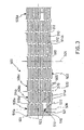
Figure 1 is a perspective view of an expanded endoluminal prosthesis portion, in accordance with a first embodiment; - .
Figure 2 is a plane development of a portion of the prosthesis fromFigure 1 ; - .
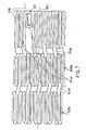
Figure 3 is a plane development of the prosthesis fromFigure 1 in the collapsed state; - .
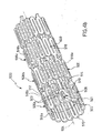
Figure 4a is a perspective view of a portion of the prosthesis fromFigure 1 in the collapsed state; - .
Figure 4b is a perspective view of the collapsed prosthesis in accordance with a further embodiment; - .
Figure 5 illustrates a detail of the plane development of the prosthesis fromFigure 1 when collapsed; - .
Figure 6 is a view of a detail of the prosthesis fromFigure 1 when expanded; - .
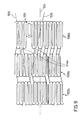
Figure 7 illustrates a detail of a plane development of a collapsed endoluminal prosthesis according to a further embodiment; - .
Figure 8 is a view of a detail of the prosthesis fromFigure 7 when expanded; - .
Figure 9 illustrates a detail of a plane development of a collapsed endoluminal prosthesis according to a still further embodiment; - .
Figure 10 is a view of a detail of the prosthesis fromFigure 9 when expanded; - .
Figure 11 illustrates a detail of a plane development of a collapsed endoluminal prosthesis according to a further embodiment; - .
Figure 12 is a view of a detail of the prosthesis fromfigure 11 , when expanded; - .
Figures 13 and14 are perspective views of a detail of the prosthesis fromFigure 1 when expanded, wherein the stress condition and the corresponding strain condition are highlighted; - .
Figures 15 and16 are perspective views of a detail of the prosthesis fromfigure 7 when expanded, wherein the stress condition and the corresponding strain condition are highlighted; - .
Figures 17 and18 are perspective views of a detail of the prosthesis fromfigure 9 when expanded, wherein the stress condition and the corresponding strain condition are highlighted; - .
Figures 19 and20 are a perspective view of a detail of the prosthesis fromfigure 11 when expanded, wherein the stress condition and the corresponding strain condition are highlighted; - .
Figures 21 to 26 are views of six expansion steps of the prosthesis fromFigure 1 . - . With reference to the above mentioned figures, with 500 has been indicated an endoluminal prosthesis as a whole, such as a prosthesis of the self-expanding type for ducts or vessels of living bodies, such as blood vessels and bile ducts or gastro-intestinal ducts or similar.
- . In accordance with a general embodiment of the present invention, the endoluminal prosthesis comprises a
tubular body 502 suitable to turn from a collapsed condition to an expanded or partially expanded condition. - . By "collapsed condition" is meant a state of the prosthesis as being contracted such as to have a smaller bulk than in an operating use condition, e.g. a condition where the
tubular body 502 has a smaller size or outer diameter than in an operating use condition. For example, the prosthesis is arranged in a collapsed condition when it is either accommodated or arranged on a transport and delivery device suitable to travel along a duct or vessel to the area to be treated. For example, in the case of a self-expanding prosthesis, this is accommodated in a sheath such as to be maintained in the collapsed condition (Figure 4 and21 ). - . By "expanded or partially expanded condition" is meant a condition where the prosthesis is free from restrictions or an operating use condition with the prosthesis being widened upon pressure contact against the inner surfaces of a duct or vessel walls (
figures 1 ,6 and26 where it is illustrated with an expanded and a partially expanded length). - . The
tubular body 502 develops along alongitudinal axis 504. - . By "longitudinal axis" is meant for example either a symmetry axis of a cylindrical body or the stretch axial direction of a tubular body.
- . The
tubular body 502 comprises a plurality ofserpentines - . By "serpentine" is meant a zig-zag/to-and-fro developing element around a main direction of stretching. [0037]. Each of these serpentines comprising either arm portions or
arms 510 ofpredetermined length 600 transversal to their main longitudinal stretch.. - . Each of said
serpentines subsequent arms 510 to form said meander path. - . Advantageously, at least a
bridge adjacent serpentines - . With further advantage, the
bends 512 facing anadjacent serpentine serpentine - . Preferably, the at least one
bridge adjacent serpentines - . Advantageously, the at least one
bridge length 602 transversal to its main longitudinal direction which has a greater value than thelength 600 ofarms 510. - . According to a possible embodiment, an
endoluminal prosthesis 500 comprises atubular body 502 developing along alongitudinal axis 504. The tubular body comprises a plurality of serpentines ormeander paths circumpherential direction 508 relative to the direction of the longitudinal axis of the endoluminal prosthesis. Thecircumpherential direction 508 is illustrated inFigure 4a with reference to the perspective view of the prosthesis in a closed configuration and infigure 3 and5 with reference to the plane development of thetubular body 502 of the prosthesis in a closed configuration. - . A serpentine comprises
arms 510 connected bybends 512. According to a possible embodiment, the arms are substantially straight. - . In accordance with a possible embodiment, the arms are connected by bends such as to form a sequence of peaks and valleys along the circumpherential direction of the corresponding serpentines. With reference to an end portion of a prosthesis such as illustrated in
figure 1 or5 , for simplicity of exposition those bends being convex towards the outside of the prosthesis will be identified aspeaks 516a and those bends being concave towards the outside of the prosthesis, i.e. moving away from amiddle axis 524, will be identified asvalleys 516b. - . Two adjacent serpentines are connected by at least one
bridge - . With
references - . According to a possible embodiment, the plurality of serpentines comprise a
first serpentine 506a, asecond serpentine 506b and a third serpentine, 506c. Preferably, thesecond serpentine 506b and thethird serpentine 506c repeat alternatively along the longitudinal axis. Still more preferably, the second serpentine and the third serpentine are substantially identical. Furthermore, they can be arranged specularly relative to acircumpherential direction 520 intermediate between both serpentines. With reference to the embodiment illustrated in the figures, the second and third serpentines can be arranged specularly relative to acircumpherential direction 520 intermediate between both serpentines and staggered to one another along the circumpherential direction. - . In accordance with one embodiment, said at least one
bridge 514 is joined with abend 512 of a serpentine 506a or 506b or 506c and with abend 512 of anopposite serpentine - . Advantageously, the at least one
bridge constant width 602 all along its longitudinal stretch. Preferably, the at least onebridge width 602 substantially equal to twice thewidth 600 ofarms 510. With a further advantage, the at least onebridge bridge - . In accordance with one embodiment, at least one
bridge adjacent serpentines - . Advantageously, a plurality of
bridges adjacent serpentines - . In accordance with one embodiment, between at least two
adjacent serpentines bridge 514b is provided every four bends 512 as counted along the path of each serpentine. - . In accordance with a further embodiment, between at least two
adjacent serpentines bridge 514b is provided every six bends 510 as counted along the path of each serpentine. - . In accordance with a still further embodiment, between at least two
adjacent serpentines bridge 514b is provided every ten bends 510 as counted along the path of each serpentine. - . Advantageously, the at least one
bridge direction 606 tangential to thetubular body 502 and biased relative to anaxis 604 parallel to thelongitudinal axis 504 of said body (for example by an angle designated with the reference a or b) . - . Preferably, all the
bridges 514b between at least twoadjacent serpentines - . In accordance with one embodiment, by going through the
prosthesis 500 in a longitudinal way, e.g. from a first proximal end to a second distal end of the prosthesis, one encounter bridges 514b alternating with one another with opposite way direction biases (a and b) relative to anaxis 604 parallel to the longitudinal axis of the tubular body. - . Advantageously, by going through the
prosthesis 500 in a longitudinal way, one encounters thebridges 514b alternating with one another with direction biases a, b of opposite value ("a" having the same value as and opposite way to "b") relative to anaxis 604 parallel to the longitudinal axis of the tubular body. - . In accordance with one embodiment, the prosthesis comprises a
cell adjoining serpentines subsequent bridges subsequent bridges dotted line 518b inFigure 2 ). - . In accordance with one embodiment, the
arms 510 are substantially straight. In other words, an arm extends without forming any bend, or fold, between a connecting or joint portion thereof to afirst bend 512 and a second connecting or joint portion thereof to asecond bend 512. - . Advantageously, the
arms 510 comprise substantially straight edges. - . In accordance with one embodiment, at least one
cell 518b comprises sixcomplete bends 512. - . In accordance with a further embodiment, at least one
cell 518b comprises tencomplete bends 512. - . In accordance with a still further embodiment, at least one
cell 518b comprises eighteencomplete bends 512. - . Advantageously, according to one embodiment, at least one
prosthesis 500 length, when being in a collapsed state, comprises a plurality ofserpentines bends 512, facing the same end as theprosthesis 500, such as the proximal end, either circumpherentially aligned with one another, or on thesame axis 610 parallel tolongitudinal axis 504 oftubular body 502. With further advantage, said at least one length of prosthesis is an intermediate portion of the prosthesis or, preferably, a middle length of theprosthesis 500. - . In accordance with one embodiment, said
prosthesis 500 is a unique body. For example, saidbody 502 is obtained by cutting a tubular element, preferably by laser cutting. - . Advantageously, said body is made of a superelastic material. In accordance with a different embodiment, said body is made of a strain hardened pseudoelastic material. In other words, a material being in the austenitic state at room temperature (Af<15°C) when annealed can be used, to which is then applied a sufficient strain hardening, such as greater than 30%, which allows to get 3%-4% elastic recovery after deformation or greater. Preferably, 50% strain hardening is applied.
- . In accordance with an embodiment, said
body 502 is made of a shape memory material. - . Advantageously, said body is made of Nitinol, or a Ni and Ti based alloy, such as with Nickel nominal weight percentage of 55,8%.
- . For example, a material with Austenite-to-Martensite phase transition can be used that, when being in the annealed or stress-relieved state, during a heating of the same the higher temperature of the end of austenite transformation, or Af, is lower than 15°C.
- . In accordance with the invention, the
first serpentine 506a comprises at least oneframe 521 defining a slot orhousing 522. Theframe 521 is arranged at a bend between two arms. Particularly, theframe 521 and theslot 522 can be arranged in place of at least two arms and one bend relative to the second or third serpentines. - . According to a possible embodiment, the second serpentine and the third serpentine comprise the same number of arms and the same number of bends.
- . Preferably the
frame 521 and theslot 522 are arranged at the bend between two arms in place of four arms and three bends relative to the second or third serpentines. Infigure 5 the arms and the bends replaced by the slot have been illustrated with a dotted line. - . Advantageously the
frame 521 occupies the whole length left free by the replaced arms and bends, as measured along the circumpherential direction and when the endoluminal prosthesis is in the collapsed condition. - . In accordance with a possible embodiment, the slot or
housing 522 passes all through the thickness of thetubular body 502. - . Advantageously the
frame 521 is arranged in the concave part of the bend between both arms directly connected to theframe 521. - . According to a possible embodiment, the prosthesis is formed as a unique body from a
tubular body 502 by cutting, such as laser cutting of a cylindrical wall thereof. - . Advantageously, the
frame 521 is formed as a unique body in thetubular body 502 obtained by laser cutting of a cylindrical wall. - . In accordance with a possible embodiment, the
slot 522 has an elongated shape in the direction of the longitudinal axis of the prosthesis, preferably elliptical or rectangular with short rounded sides. Advantageously, theframe 522 has an elongated shape in the direction of the longitudinal axis of the prosthesis. Preferably the short side offrame 521 corresponding to the bend between both arms directly connected to the frame itself is substantially straight along the circumpherential direction, when considered in a plane development of the prosthesis. - . Advantageously both arms directly connected to the
frame 521 join to the frame itself at end points. - . Advantageously the
frame 521 comprises twoelongated sides 523 having substantially the same width as thearms 510 of the prosthesis, as measured along thecircumpherential direction 508, and a shorter length than thearms 510 of the prosthesis, as measured along thelongitudinal direction 504 thereof. - . Advantageously, a radiopaque material is provided within the
slot 522, preferably melted within the slot. The radiopaque material may be any material having a greater visibility to X-rays than the material used for the prosthesis. - . In the case where the prosthesis is made of a superelastic or shape memory material, such as Nitinol (or an alloy with Ni and Ti as the main part), the radiopaque material can be selected from Tantalum, Gold, Platinum, Tungsten or other materials suitable for the purpose.
- . According to a possible embodiment, the
first serpentine 506a housing theframe 521 is an end serpentine of the prosthesis. Advantageously, both end serpentines of the prosthesis, i.e. the first and last serpentines, comprise at least oneframe 521, respectively. In other words, in a possible embodiment of the prosthesis according to the present invention, by going through the prosthesis along thelongitudinal axis 504 starting from an end of the prosthesis itself, such as a proximal end, one encounters a first serpentine or end serpentine, a sequence of alternated second and third serpentines and a last serpentine or further end serpentine, or distal end serpentine. In accordance with a possible embodiment, the last serpentine or further end serpentine specularly reproduces the first serpentine relative to amiddle axis 524 of the prosthesis, possibly staggered along the circumpherential direction. - . In accordance with an advantageous embodiment, the
frame 522 is arranged at an end bend, i.e. a bend belonging to the end serpentine and with its concavity facing the inside of the prosthesis, i.e. themiddle axis 524. In other words, theframe 521 is arranged at or in place of apeak 516a, preferably within the concavity thereof. - . Considering a
cell 518a comprising theframe 521 and defined between a length of theend serpentine 506a and a length of thesecond serpentine 506b, theframe 521 is advantageously arranged inside the respective cell. - . In accordance with a possible embodiment, the
frame 521 has an elongated shape in the direction of the longitudinal axis of the prosthesis and develops from the end bend towards amiddle axis 524 of the endoluminal prosthesis. - . By designating with 518a the cell defined between the first and the second serpentines and comprising the
frame 521, this cell comprises twobridges 514a developing alongdirections 526 tangential to the tubular body. Bothbridges 514a may be advantageously arranged alongdirections 526 substantially parallel to one another and further parallel to the development directions of the remainingbridges 514b between the first and the second serpentines. Still more advantageously, bothbridges 514a may be arranged alongdirections 526 incident to one another, both in a closed configuration and in an expanded configuration of the prosthesis (figures 2 ,3 ). - . In accordance with a possible embodiment, the
bridges 514a belonging to thecell 518a comprising theframe 521 develop alongdirections 526 converging from the end of the prosthesis towards amiddle axis 524 of the prosthesis itself. - . In accordance with an embodiment, the
bridges 514a develop according todirections 526 tangential to the tubular body and biased relative to an axis parallel to thelongitudinal axis 504 of the endoluminal prosthesis. - . Advantageously, the
bridges 514a ofcell 518a comprising theframe 521 develop alongdirections 526 tangential to the tubular body and biased relative to thelongitudinal axis 504 of the endoluminal prosthesis. - . In accordance with a possible embodiment, by designating with 514b the bridges connecting the first and the second serpentines which do not belong to
cell 518a comprising theframe 521, thesebridges 514b are substantially parallel to at least one of thebridges 514a belonging to thecell 518a comprising theslot 522. - . Advantageously, in the
cell 518a comprising theframe 521, the number of arms and bends of the first serpentine length is lower than the number of arms and bends of the second serpentine length. For example in thecell 518a comprising theframe 521, the length belonging to the first serpentine may comprise at least two arms and two bends less than the arms and bends of the length belonging to the second serpentine, as specularly counted between both serpentines. In the example fromfigure 2 , starting from one of thebridges 514a, the length of the first serpentine belonging to thecell 518a containing the slot comprises six arms and five bends while the length of second serpentine belonging to the cell 518 containing theframe 521 comprises eight arms and seven bends. - . In
figure 5 is shown a plane development of a possible embodiment of the endoluminal prosthesis according to the present invention. - . According to a possible embodiment, such as illustrated in
Figure 5 , with 528 has been designated a further cell of a different shape than thecell 518a containing theframe 521 and the remainingcells 518b of the endoluminal prosthesis. For simplicity of description thefurther cell 528 will be indicated as the "anomalous" cell. - . The
anomalous cell 528 is defined between the first and second serpentines and preferably adjacent to thecell 518a containing the slot. Advantageously theanomalous cell 528 shares abridge 514a withcell 518a containing the slot and preferably shares that bridge which develops along a direction tangential to the tubular body incident to the development directions of the remaining bridges provided between the first and the second serpentines. The "anomalous" cell comprises two arms and two bends more than the remainingcells 518b of the prosthesis. For example, the anomalous cell comprises six arms and five bends on the length relative to the second serpentine while the remainingcells 518b of the prosthesis comprise four arms and three bends, with reference to a length relative to a serpentine. - . >From what has been discussed above, it should be appreciated that providing an endoluminal prosthesis according to the present invention allows to meet the requirement of visibility to X-rays, or however to radioscopy, of the prosthesis itself while maintaining its structure solid and avoiding that parts may protrude outside the prosthesis.
- . The original provision of replacing some arms and bends of the serpentine to insert the slot and the radiopaque material enables the prosthesis to deploy evenly all along the longitudinal development thereof, simplifying at the same time the manufacturing steps of the prosthesis itself.
- . By providing the cell comprising the frame with arms developing along directions tangential to the tubular body which are incident to one another, local distortions due to the difference in arms and bends between the serpentines can be prevented. This aspect is enhanced by the presence of the anomalous cell adjacent to the cell containing the slot.
- .
Figure 6 illustrates a partial perspective view of the above prosthesis in a deformed configuration with reference to the end comprising theframe 521. - .
Figures 7 ,9 ,11 illustrate the plane development of respective three possible embodiments of the prosthesis according to the present invention.Figure 7 represents an embodiment similar to that offigures 3 or5 wherein thebridges 514a corresponding to the cell comprising theframe 521 develop alongdirections 526 tangential to the tubular body, biased relative to thelongitudinal axis 504 and parallel to one another. These directions are further parallel to the tangential directions along which theother bridges 514b develop between the first and second serpentines.Figures 9 and11 represent two types of prosthesis where the cells defined between the second and third serpentines are of a different configuration compared to that of the cells between the second and third serpentines of the embodiments fromfigures 3 ,5 or7 . Furthermore, the prosthesis fromfigure 9 has the bridges ofcell 518a containing theframe 521 that develop alongdirections 526 tangential to the tubular body and biased relative to the longitudinal axis and incident to one another. On the other hand, in the prosthesis fromfigure 11 the bridges of thecell 518a containing theframe 521 develop alongdirections 526 tangential to the tubular body and biased relative to the longitudinal axis and parallel to one another. - .
Figures 8 ,10 ,12 illustrate the prosthesis fromfigures 7 ,9 ,11 respectively, in an expanded or widened configuration. - .
Figures 13 ,14 illustrate the stresses and strains at theframe 521 in the prosthesis fromfigures 3 ,5 , respectively.Figures 15 ,16 illustrate the stresses and strains at theframe 521 in the prosthesis fromfigures 7 ,8 , respectively.Figures 17 ,18 illustrate the stresses and strains at theframe 521 in the prosthesis fromfigures 9 ,10 , respectively.Figures 19 ,20 illustrate the stresses and strains at theframe 521 in the prosthesis fromfigure 11 ,12 , respectively. Arrow F designates the greatest stress-strain area. The prosthesis illustrated infigures 3 ,5 allows to achieve a very low stress-strain peak value, and however a more constant distribution or gradual variation of the stress state. - . The above has been achieved both by the advantageous embodiment of the
frame 521 to accommodate the radiopaque material and by the overall synergy between theframe 521 and the overall geometry of the prosthesis. - . Thanks to the prosthesis thus provided, it is possible to carry out endoluminal operations in tortuous vessels or ducts, and at the same time, an optimum and constant support of the treated vessel wall can also be ensured with the prosthesis being in the expanded state.
- .
Figures 21 to 26 illustrate six release steps from asheath 612 of a self-expandingendoluminal prosthesis 500. This procedure is, for example, carried out by withdrawing the sheath such that the prosthesis is left free to expand, such as from a housing where it is accommodated as provided in a transport and release device, such as a catheter (not shown herein). - . It should be understood that variants and/or additions may be provided to what has been described and illustrated above.
- . The slot can be of any shape other than that illustrated in the figures. Furthermore, it could be provided in a serpentine different from the serpentine end, or in a bend corresponding to a valley with reference to the meaning of the term "valley" such as discussed above.
- . The number of serpentines, arms or bends may be changed from what has been described or illustrated. The shape of the serpentines may also be changed, particularly the alternate repetition between the second and third serpentines. For example, the second and third serpentines may be either equal, or perfectly specular without resulting staggered in the circumpherential direction.
- . Generally all the embodiments which have been described as possible above, can be made as such, in the absence of those characteristics described as belonging to other possible embodiments.
- To the above preferred embodiments of the endoluminal prosthesis, those skilled in the art, aiming at satisfying contingent and specific needs, may carry out a number of modifications, variants and replacements of elements with others functionally equivalent, without departing from the scope of the claims below.
Claims (37)
- Endoluminal prosthesis (500) comprising:a tubular body developing along a longitudinal axis,said tubular body (502) comprising a plurality of serpentines or meander paths (506) developing along a substantially circumpherential direction relative to the direction of the longitudinal axis of the endoluminal prosthesis, said serpentines comprising arms connected by bends,wherein two adjacent serpentines are connected by at least one bridge (514) thus forming at least two cells between said two adjacent serpentines,
characterized in that at least one serpentine comprises at least one frame (521) defining a slot (522) arranged at the bend between two arms in place of at least two arms and one bend compared to a second serpentine,
a radiopaque material being provided within said slot. - Prosthesis according to the preceding claim, wherein said plurality of serpentines comprises a first serpentine and a second serpentine, said first serpentine forming only end lengths of said prosthesis.
- Prosthesis according to the preceding claim, wherein said plurality of serpentines comprises a first serpentine, a second serpentine and a third serpentine, said second and third serpentines alternatively repeating along said longitudinal axis.
- Endoluminal prosthesis according to claims 1 or 2 or 3
wherein said at least one serpentine is a first serpentine. - Endoluminal prosthesis according to claim 1 wherein said frame is arranged at the bend between both arms in place of four arms and three bends relative to second or third serpentines.
- Endoluminal prosthesis according to claim 1 or 2 or 3 wherein said frame is arranged on the concave part of the bend.
- Endoluminal prosthesis according to one of preceding claims, wherein said first serpentine is an end serpentine of the prosthesis.
- Endoluminal prosthesis according to claim 7,
wherein said frame is arranged at an end bend or peak of the serpentine. - Endoluminal prosthesis according to claim 8,
wherein said frame is arranged within the corresponding cell as defined between the first and the second serpentines. - Endoluminal prosthesis according to one of preceding claims, wherein said frame has an elongated shape in the direction of the longitudinal axis of the prosthesis.
- Endoluminal prosthesis according to claim 10
wherein said frame develops from the end bend towards a middle axis of the endoluminal prosthesis. - Endoluminal prosthesis according to one of claims 1 to 11
wherein between the first and second serpentines a cell is defined which comprises said frame, said cell comprising two bridges developing along directions tangential to the tubular body, which are incident to one another. - Endoluminal prosthesis according to one of claims 1 to 11,
wherein between the first and the second serpentine a cell is defined which comprises said frame, said cell comprising two bridges developing along directions tangential to the tubular body, which are parallel to one another. - Endoluminal prosthesis according to claim 12,
wherein the bridges of the cell comprising said frame develop along directions tangential to the tubular body converging from the end to a middle axis of the prosthesis. - Endoluminal prosthesis according to claims 12 or 13 or 14,
wherein the bridges of the cell comprising said frame develop according to directions tangential to the tubular body which are biased relative to the longitudinal axis of the endoluminal prosthesis. - Endoluminal prosthesis according to one of claim 12 to 15,
wherein the connecting bridges between the first and second serpentines that do not belong to the cell comprising said frame are substantially parallel to one of those bridges belonging to the cell comprising said slot. - Endoluminal prosthesis according to one of claims 12 to 16,
wherein in the cell comprising said frame the number of arms and bends of the first serpentine is lower than the number of arms and bends of the second serpentine. - Endoluminal prosthesis according to claim 17,
wherein in the cell comprising said frame the length belonging to the first serpentine comprises two arms and two bends less than the arms and bends of the length belonging to the second serpentine, as specularly counted between both serpentines starting from junction points. - Endoluminal prosthesis according to claim 18
wherein in the cell comprising said frame the length belonging to the first serpentine comprises six arms and five bends whereas the length belonging to the second serpentine comprises eight arms and seven bends. - Endoluminal prosthesis according to one of preceding claims, wherein said slot passes all through the thickness of the tubular body.
- Endoluminal prosthesis according to one of preceding claims, wherein said radiopaque material is either melted or welded within the slot.
- Endoluminal prosthesis according to one of preceding claims, wherein said second and third serpentines are specular relative to a circumpherential direction intermediate between both serpentines and staggered to one another.
- Endoluminal prosthesis according to one of preceding claims, wherein two frames are provided arranged in end serpentines of the prosthesis, respectively.
- Endoluminal prosthesis according to claim 23,
wherein the end serpentines are specular to one another relative to a middle axis of the prosthesis. - Endoluminal prosthesis according to claim 24, Endoluminal prosthesis according to claim 24,
wherein the end serpentines are specular to one another relative to a middle axis of the prosthesis and staggered in the circumpherential direction. - Endoluminal prosthesis according to one of preceding claims, wherein at least one anomalous cell is provided being defined between the first and second serpentines, said anomalous cell being different both from the cell containing said frame and the remaining cells of the prosthesis.
- Endoluminal prosthesis according to claim 26,
wherein said anomalous cell is adjacent to the cell containing said frame, sharing a connecting bridge therewith. - Endoluminal prosthesis according to claim 27,
wherein the anomalous cell shares with the cell containing the frame the bridge developing along a direction tangential to the tubular body incident to the directions of development of the remaining bridges provided between the first and second serpentines. - Endoluminal prosthesis according to one of claims 26 to 28,
wherein the anomalous cell comprises two arms and two bends more than the remaining cells of the prosthesis which do not contain the frame. - Endoluminal prosthesis according to claim 29,
wherein the anomalous cell comprises on the length corresponding to the second serpentine six arms and five bends, whereas the remaining cells of the prosthesis comprise, with reference to a length corresponding to a serpentine, four arms and three bends. - Endoluminal prosthesis according to one of preceding claims, wherein said frame occupies the whole width which has been left free by the replaced arms and bends, as measured along the circumpherential direction.
- Endoluminal prosthesis according to one of preceding claims, wherein said frame is formed as a unique body in the tubular body by laser cutting a cylindrical wall.
- Endoluminal prosthesis according to one of preceding claims, wherein said slot has an elongated shape along the direction of the longitudinal axis of the prosthesis.
- Endoluminal prosthesis according to one of preceding claims, wherein an end side of the frame is substantially straight along the circumpherential direction, in a plane development of the prosthesis.
- Endoluminal prosthesis according to one of preceding claims, wherein the arms directly connected to the frame join thereto at end points of the frame itself.
- Endoluminal prosthesis according to one of preceding claims, wherein said frame comprises elongated sides having substantially the same width as the prosthesis arms, as measured along the circumpherential direction, and the length being shorter than the prosthesis arms, as measured along the longitudinal direction.
- Endoluminal prosthesis according to one of preceding claims, wherein a serpentine is closed along the circumpherential direction of the prosthesis.
Applications Claiming Priority (1)
| Application Number | Priority Date | Filing Date | Title |
|---|---|---|---|
| PCT/IT2004/000249 WO2005104991A1 (en) | 2004-05-05 | 2004-05-05 | Endoluminal prosthesis |
Publications (3)
| Publication Number | Publication Date |
|---|---|
| EP1744705A1 EP1744705A1 (en) | 2007-01-24 |
| EP1744705B1 true EP1744705B1 (en) | 2009-08-05 |
| EP1744705B8 EP1744705B8 (en) | 2009-10-07 |
Family
ID=34957766
Family Applications (1)
| Application Number | Title | Priority Date | Filing Date |
|---|---|---|---|
| EP04731261A Not-in-force EP1744705B8 (en) | 2004-05-05 | 2004-05-05 | Endoluminal prosthesis |
Country Status (10)
| Country | Link |
|---|---|
| US (1) | US7722659B2 (en) |
| EP (1) | EP1744705B8 (en) |
| JP (1) | JP5007888B2 (en) |
| CN (1) | CN1988857B (en) |
| AT (1) | ATE438364T1 (en) |
| BR (1) | BRPI0418719A (en) |
| DE (1) | DE602004022461D1 (en) |
| ES (1) | ES2331129T3 (en) |
| HK (1) | HK1099195A1 (en) |
| WO (1) | WO2005104991A1 (en) |
Families Citing this family (19)
| Publication number | Priority date | Publication date | Assignee | Title |
|---|---|---|---|---|
| GB0020491D0 (en) | 2000-08-18 | 2000-10-11 | Angiomed Ag | Stent with attached element and method of making such a stent |
| NZ569760A (en) | 2006-02-17 | 2011-01-28 | Invatec Srl | Endoluminal prosthesis |
| GB0609841D0 (en) | 2006-05-17 | 2006-06-28 | Angiomed Ag | Bend-capable tubular prosthesis |
| GB0609911D0 (en) | 2006-05-18 | 2006-06-28 | Angiomed Ag | Bend-capable stent prosthesis |
| DE102006038242A1 (en) * | 2006-08-07 | 2008-02-14 | Biotronik Vi Patent Ag | Stent with a structure made of a biocorrodible metallic material |
| GB0616579D0 (en) | 2006-08-21 | 2006-09-27 | Angiomed Ag | Self-expanding stent |
| GB0616999D0 (en) | 2006-08-29 | 2006-10-04 | Angiomed Ag | Annular mesh |
| WO2008028964A2 (en) | 2006-09-07 | 2008-03-13 | Angiomed Gmbh & Co. Medizintechnik Kg | Helical implant having different ends |
| GB0622465D0 (en) | 2006-11-10 | 2006-12-20 | Angiomed Ag | Stent |
| GB0624419D0 (en) | 2006-12-06 | 2007-01-17 | Angiomed Ag | Stenting ring with marker |
| EP2110103A4 (en) * | 2007-02-09 | 2014-07-30 | Piolax Medical Devices Inc | Stent |
| BRPI0721499A2 (en) * | 2007-03-23 | 2013-01-08 | Invatec Technology Ct Gmbh | endoluminal prosthesis |
| GB0706499D0 (en) | 2007-04-03 | 2007-05-09 | Angiomed Ag | Bendable stent |
| GB0717481D0 (en) | 2007-09-07 | 2007-10-17 | Angiomed Ag | Self-expansible stent with radiopaque markers |
| DE102010009802A1 (en) * | 2010-03-01 | 2011-09-01 | Qualimed Innovative Medizinprodukte Gmbh | Radially expandable stent |
| AU2013337199A1 (en) * | 2012-10-26 | 2014-08-14 | Zhejiang Zylox Medical Device Co., Ltd. | Self-expanding stent |
| JP2014226353A (en) * | 2013-05-23 | 2014-12-08 | ニプロ株式会社 | Stent |
| CN105193532A (en) * | 2015-10-30 | 2015-12-30 | 加奇生物科技(上海)有限公司苏州分公司 | Carotid artery stent system |
| WO2017180398A1 (en) * | 2016-04-14 | 2017-10-19 | Medtronic Vascular Inc. | Guide extension catheter with helically-shaped entry port |
Family Cites Families (22)
| Publication number | Priority date | Publication date | Assignee | Title |
|---|---|---|---|---|
| CA1232814A (en) | 1983-09-16 | 1988-02-16 | Hidetoshi Sakamoto | Guide wire for catheter |
| US4665771A (en) | 1984-10-15 | 1987-05-19 | Mitchell Frank R | Hypocyclic drive |
| US4665905A (en) | 1986-06-09 | 1987-05-19 | Brown Charles S | Dynamic elbow and knee extension brace |
| US7204848B1 (en) | 1995-03-01 | 2007-04-17 | Boston Scientific Scimed, Inc. | Longitudinally flexible expandable stent |
| US6602281B1 (en) * | 1995-06-05 | 2003-08-05 | Avantec Vascular Corporation | Radially expansible vessel scaffold having beams and expansion joints |
| US6451049B2 (en) * | 1998-04-29 | 2002-09-17 | Sorin Biomedica Cardio, S.P.A. | Stents for angioplasty |
| ES2290995T3 (en) * | 1997-09-24 | 2008-02-16 | Med Institute, Inc. | RADIALLY EXPANDABLE ENDOPROTESIS. |
| US6342067B1 (en) | 1998-01-09 | 2002-01-29 | Nitinol Development Corporation | Intravascular stent having curved bridges for connecting adjacent hoops |
| ATE376401T1 (en) * | 1998-11-20 | 2007-11-15 | Boston Scient Ltd | LONGITUDONLY FLEXIBLE AND EXPANDABLE STENT |
| KR20010089543A (en) | 1998-12-18 | 2001-10-06 | 쿡 인코포레이티드 | Cannula Stent |
| US8070792B2 (en) * | 2000-09-22 | 2011-12-06 | Boston Scientific Scimed, Inc. | Stent |
| US8197535B2 (en) * | 2001-06-19 | 2012-06-12 | Cordis Corporation | Low profile improved radiopacity intraluminal medical device |
| CN2517403Y (en) * | 2001-07-27 | 2002-10-23 | 微创医疗器械(上海)有限公司 | Coronary artery stand with non-homogeneous waveform structure |
| DE10243136A1 (en) * | 2002-09-17 | 2004-05-19 | Campus Medizin & Technik Gmbh | Stent for implantation in or around a hollow organ |
| US7331986B2 (en) | 2002-10-09 | 2008-02-19 | Boston Scientific Scimed, Inc. | Intraluminal medical device having improved visibility |
| US7914567B2 (en) * | 2002-11-22 | 2011-03-29 | Oregon Health & Science University | Stent tissue graft prosthesis |
| US7247166B2 (en) * | 2003-09-29 | 2007-07-24 | Advanced Cardiovascular Systems, Inc. | Intravascular stent with extendible end rings |
| US7744641B2 (en) * | 2004-07-21 | 2010-06-29 | Boston Scientific Scimed, Inc. | Expandable framework with overlapping connectors |
| KR100778020B1 (en) * | 2005-10-24 | 2007-11-28 | 사회복지법인 삼성생명공익재단 | Vascular stent which is specially designed for the multiple drug loading and better drug elution |
| US7381217B2 (en) * | 2005-12-23 | 2008-06-03 | Boston Scientific Scimed, Inc. | Serpentine stent pattern |
| NZ569760A (en) * | 2006-02-17 | 2011-01-28 | Invatec Srl | Endoluminal prosthesis |
| EP2144580B1 (en) * | 2007-04-09 | 2015-08-12 | Covidien LP | Stent delivery system |
-
2004
- 2004-05-05 US US11/568,468 patent/US7722659B2/en active Active
- 2004-05-05 WO PCT/IT2004/000249 patent/WO2005104991A1/en active Application Filing
- 2004-05-05 ES ES04731261T patent/ES2331129T3/en active Active
- 2004-05-05 BR BRPI0418719-9A patent/BRPI0418719A/en not_active IP Right Cessation
- 2004-05-05 CN CN200480042969XA patent/CN1988857B/en not_active Expired - Fee Related
- 2004-05-05 AT AT04731261T patent/ATE438364T1/en not_active IP Right Cessation
- 2004-05-05 DE DE602004022461T patent/DE602004022461D1/en active Active
- 2004-05-05 EP EP04731261A patent/EP1744705B8/en not_active Not-in-force
- 2004-05-05 JP JP2007512726A patent/JP5007888B2/en not_active Expired - Fee Related
-
2007
- 2007-06-25 HK HK07106787.7A patent/HK1099195A1/en not_active IP Right Cessation
Also Published As
| Publication number | Publication date |
|---|---|
| CN1988857B (en) | 2010-09-08 |
| US20080221662A1 (en) | 2008-09-11 |
| DE602004022461D1 (en) | 2009-09-17 |
| EP1744705A1 (en) | 2007-01-24 |
| US20090182414A9 (en) | 2009-07-16 |
| EP1744705B8 (en) | 2009-10-07 |
| JP5007888B2 (en) | 2012-08-22 |
| CN1988857A (en) | 2007-06-27 |
| HK1099195A1 (en) | 2007-08-10 |
| US7722659B2 (en) | 2010-05-25 |
| WO2005104991A8 (en) | 2006-12-07 |
| ES2331129T3 (en) | 2009-12-22 |
| JP2007536056A (en) | 2007-12-13 |
| WO2005104991A1 (en) | 2005-11-10 |
| ATE438364T1 (en) | 2009-08-15 |
| BRPI0418719A (en) | 2007-09-11 |
Similar Documents
| Publication | Publication Date | Title |
|---|---|---|
| EP1744705B1 (en) | Endoluminal prosthesis | |
| AU2006338440B2 (en) | Endoluminal prosthesis | |
| US7204848B1 (en) | Longitudinally flexible expandable stent | |
| US8075610B2 (en) | Endoprosthesis for controlled contraction and expansion | |
| CA2316286C (en) | Longitudinally flexible expandable stent | |
| US8876888B2 (en) | Stent with offset cell geometry | |
| JP2001259041A (en) | Stent flexible in longitudinal direction | |
| CA2358453A1 (en) | Expandable endovascular medical tubular stent | |
| US7691142B2 (en) | Stent | |
| RU2393820C2 (en) | Intraluminal prosthesis |
Legal Events
| Date | Code | Title | Description |
|---|---|---|---|
| PUAI | Public reference made under article 153(3) epc to a published international application that has entered the european phase |
Free format text: ORIGINAL CODE: 0009012 |
|
| 17P | Request for examination filed |
Effective date: 20061017 |
|
| AK | Designated contracting states |
Kind code of ref document: A1 Designated state(s): AT BE BG CH CY CZ DE DK EE ES FI FR GB GR HU IE IT LI LU MC NL PL PT RO SE SI SK TR |
|
| DAX | Request for extension of the european patent (deleted) | ||
| REG | Reference to a national code |
Ref country code: HK Ref legal event code: DE Ref document number: 1099195 Country of ref document: HK |
|
| 17Q | First examination report despatched |
Effective date: 20080115 |
|
| GRAP | Despatch of communication of intention to grant a patent |
Free format text: ORIGINAL CODE: EPIDOSNIGR1 |
|
| RIC1 | Information provided on ipc code assigned before grant |
Ipc: A61F 2/90 20060101AFI20090119BHEP |
|
| GRAS | Grant fee paid |
Free format text: ORIGINAL CODE: EPIDOSNIGR3 |
|
| GRAA | (expected) grant |
Free format text: ORIGINAL CODE: 0009210 |
|
| AK | Designated contracting states |
Kind code of ref document: B1 Designated state(s): AT BE BG CH CY CZ DE DK EE ES FI FR GB GR HU IE IT LI LU MC NL PL PT RO SE SI SK TR |
|
| REG | Reference to a national code |
Ref country code: GB Ref legal event code: FG4D |
|
| REG | Reference to a national code |
Ref country code: CH Ref legal event code: EP |
|
| REG | Reference to a national code |
Ref country code: IE Ref legal event code: FG4D |
|
| RAP2 | Party data changed (patent owner data changed or rights of a patent transferred) |
Owner name: INVATEC S.P.A. |
|
| REF | Corresponds to: |
Ref document number: 602004022461 Country of ref document: DE Date of ref document: 20090917 Kind code of ref document: P |
|
| REG | Reference to a national code |
Ref country code: CH Ref legal event code: NV Representative=s name: JACOBACCI & PARTNERS S.P.A. |
|
| NLT2 | Nl: modifications (of names), taken from the european patent patent bulletin |
Owner name: INVATEC S.P.A. Effective date: 20090909 |
|
| REG | Reference to a national code |
Ref country code: SE Ref legal event code: TRGR |
|
| REG | Reference to a national code |
Ref country code: ES Ref legal event code: FG2A Ref document number: 2331129 Country of ref document: ES Kind code of ref document: T3 |
|
| REG | Reference to a national code |
Ref country code: HK Ref legal event code: GR Ref document number: 1099195 Country of ref document: HK |
|
| PG25 | Lapsed in a contracting state [announced via postgrant information from national office to epo] |
Ref country code: FI Free format text: LAPSE BECAUSE OF FAILURE TO SUBMIT A TRANSLATION OF THE DESCRIPTION OR TO PAY THE FEE WITHIN THE PRESCRIBED TIME-LIMIT Effective date: 20090805 |
|
| PG25 | Lapsed in a contracting state [announced via postgrant information from national office to epo] |
Ref country code: SI Free format text: LAPSE BECAUSE OF FAILURE TO SUBMIT A TRANSLATION OF THE DESCRIPTION OR TO PAY THE FEE WITHIN THE PRESCRIBED TIME-LIMIT Effective date: 20090805 Ref country code: PL Free format text: LAPSE BECAUSE OF FAILURE TO SUBMIT A TRANSLATION OF THE DESCRIPTION OR TO PAY THE FEE WITHIN THE PRESCRIBED TIME-LIMIT Effective date: 20090805 |
|
| PG25 | Lapsed in a contracting state [announced via postgrant information from national office to epo] |
Ref country code: PT Free format text: LAPSE BECAUSE OF FAILURE TO SUBMIT A TRANSLATION OF THE DESCRIPTION OR TO PAY THE FEE WITHIN THE PRESCRIBED TIME-LIMIT Effective date: 20091205 Ref country code: BG Free format text: LAPSE BECAUSE OF FAILURE TO SUBMIT A TRANSLATION OF THE DESCRIPTION OR TO PAY THE FEE WITHIN THE PRESCRIBED TIME-LIMIT Effective date: 20091105 |
|
| PG25 | Lapsed in a contracting state [announced via postgrant information from national office to epo] |
Ref country code: RO Free format text: LAPSE BECAUSE OF FAILURE TO SUBMIT A TRANSLATION OF THE DESCRIPTION OR TO PAY THE FEE WITHIN THE PRESCRIBED TIME-LIMIT Effective date: 20090805 Ref country code: EE Free format text: LAPSE BECAUSE OF FAILURE TO SUBMIT A TRANSLATION OF THE DESCRIPTION OR TO PAY THE FEE WITHIN THE PRESCRIBED TIME-LIMIT Effective date: 20090805 Ref country code: CZ Free format text: LAPSE BECAUSE OF FAILURE TO SUBMIT A TRANSLATION OF THE DESCRIPTION OR TO PAY THE FEE WITHIN THE PRESCRIBED TIME-LIMIT Effective date: 20090805 Ref country code: DK Free format text: LAPSE BECAUSE OF FAILURE TO SUBMIT A TRANSLATION OF THE DESCRIPTION OR TO PAY THE FEE WITHIN THE PRESCRIBED TIME-LIMIT Effective date: 20090805 |
|
| PG25 | Lapsed in a contracting state [announced via postgrant information from national office to epo] |
Ref country code: SK Free format text: LAPSE BECAUSE OF FAILURE TO SUBMIT A TRANSLATION OF THE DESCRIPTION OR TO PAY THE FEE WITHIN THE PRESCRIBED TIME-LIMIT Effective date: 20090805 |
|
| PLBE | No opposition filed within time limit |
Free format text: ORIGINAL CODE: 0009261 |
|
| STAA | Information on the status of an ep patent application or granted ep patent |
Free format text: STATUS: NO OPPOSITION FILED WITHIN TIME LIMIT |
|
| 26N | No opposition filed |
Effective date: 20100507 |
|
| PGFP | Annual fee paid to national office [announced via postgrant information from national office to epo] |
Ref country code: ES Payment date: 20100520 Year of fee payment: 7 |
|
| PGFP | Annual fee paid to national office [announced via postgrant information from national office to epo] |
Ref country code: AT Payment date: 20100513 Year of fee payment: 7 Ref country code: NL Payment date: 20100514 Year of fee payment: 7 |
|
| PG25 | Lapsed in a contracting state [announced via postgrant information from national office to epo] |
Ref country code: GR Free format text: LAPSE BECAUSE OF FAILURE TO SUBMIT A TRANSLATION OF THE DESCRIPTION OR TO PAY THE FEE WITHIN THE PRESCRIBED TIME-LIMIT Effective date: 20091106 |
|
| PGFP | Annual fee paid to national office [announced via postgrant information from national office to epo] |
Ref country code: BE Payment date: 20100517 Year of fee payment: 7 |
|
| PGFP | Annual fee paid to national office [announced via postgrant information from national office to epo] |
Ref country code: GB Payment date: 20100519 Year of fee payment: 7 Ref country code: SE Payment date: 20100520 Year of fee payment: 7 |
|
| PG25 | Lapsed in a contracting state [announced via postgrant information from national office to epo] |
Ref country code: MC Free format text: LAPSE BECAUSE OF NON-PAYMENT OF DUE FEES Effective date: 20100531 |
|
| BERE | Be: lapsed |
Owner name: INVATEC S.P.A. Effective date: 20110531 |
|
| REG | Reference to a national code |
Ref country code: NL Ref legal event code: V1 Effective date: 20111201 |
|
| REG | Reference to a national code |
Ref country code: SE Ref legal event code: EUG |
|
| GBPC | Gb: european patent ceased through non-payment of renewal fee |
Effective date: 20110505 |
|
| PG25 | Lapsed in a contracting state [announced via postgrant information from national office to epo] |
Ref country code: NL Free format text: LAPSE BECAUSE OF NON-PAYMENT OF DUE FEES Effective date: 20111201 |
|
| REG | Reference to a national code |
Ref country code: AT Ref legal event code: MM01 Ref document number: 438364 Country of ref document: AT Kind code of ref document: T Effective date: 20110505 |
|
| PG25 | Lapsed in a contracting state [announced via postgrant information from national office to epo] |
Ref country code: AT Free format text: LAPSE BECAUSE OF NON-PAYMENT OF DUE FEES Effective date: 20110505 |
|
| PG25 | Lapsed in a contracting state [announced via postgrant information from national office to epo] |
Ref country code: BE Free format text: LAPSE BECAUSE OF NON-PAYMENT OF DUE FEES Effective date: 20110531 |
|
| PG25 | Lapsed in a contracting state [announced via postgrant information from national office to epo] |
Ref country code: GB Free format text: LAPSE BECAUSE OF NON-PAYMENT OF DUE FEES Effective date: 20110505 |
|
| REG | Reference to a national code |
Ref country code: ES Ref legal event code: FD2A Effective date: 20120717 |
|
| PG25 | Lapsed in a contracting state [announced via postgrant information from national office to epo] |
Ref country code: ES Free format text: LAPSE BECAUSE OF NON-PAYMENT OF DUE FEES Effective date: 20110506 |
|
| PG25 | Lapsed in a contracting state [announced via postgrant information from national office to epo] |
Ref country code: CY Free format text: LAPSE BECAUSE OF FAILURE TO SUBMIT A TRANSLATION OF THE DESCRIPTION OR TO PAY THE FEE WITHIN THE PRESCRIBED TIME-LIMIT Effective date: 20090805 |
|
| PG25 | Lapsed in a contracting state [announced via postgrant information from national office to epo] |
Ref country code: LU Free format text: LAPSE BECAUSE OF NON-PAYMENT OF DUE FEES Effective date: 20100505 Ref country code: HU Free format text: LAPSE BECAUSE OF FAILURE TO SUBMIT A TRANSLATION OF THE DESCRIPTION OR TO PAY THE FEE WITHIN THE PRESCRIBED TIME-LIMIT Effective date: 20100206 |
|
| PG25 | Lapsed in a contracting state [announced via postgrant information from national office to epo] |
Ref country code: TR Free format text: LAPSE BECAUSE OF FAILURE TO SUBMIT A TRANSLATION OF THE DESCRIPTION OR TO PAY THE FEE WITHIN THE PRESCRIBED TIME-LIMIT Effective date: 20090805 |
|
| PG25 | Lapsed in a contracting state [announced via postgrant information from national office to epo] |
Ref country code: SE Free format text: LAPSE BECAUSE OF NON-PAYMENT OF DUE FEES Effective date: 20110506 |
|
| REG | Reference to a national code |
Ref country code: CH Ref legal event code: PCAR Free format text: NEW ADDRESS: VIA LUGANETTO 3, 6962 LUGANO (CH) |
|
| REG | Reference to a national code |
Ref country code: FR Ref legal event code: PLFP Year of fee payment: 13 |
|
| REG | Reference to a national code |
Ref country code: FR Ref legal event code: PLFP Year of fee payment: 14 |
|
| REG | Reference to a national code |
Ref country code: FR Ref legal event code: PLFP Year of fee payment: 15 |
|
| PGFP | Annual fee paid to national office [announced via postgrant information from national office to epo] |
Ref country code: CH Payment date: 20180426 Year of fee payment: 15 |
|
| REG | Reference to a national code |
Ref country code: CH Ref legal event code: PL |
|
| PG25 | Lapsed in a contracting state [announced via postgrant information from national office to epo] |
Ref country code: CH Free format text: LAPSE BECAUSE OF NON-PAYMENT OF DUE FEES Effective date: 20190531 Ref country code: LI Free format text: LAPSE BECAUSE OF NON-PAYMENT OF DUE FEES Effective date: 20190531 |
|
| PGFP | Annual fee paid to national office [announced via postgrant information from national office to epo] |
Ref country code: FR Payment date: 20200422 Year of fee payment: 17 Ref country code: DE Payment date: 20200421 Year of fee payment: 17 Ref country code: IE Payment date: 20200422 Year of fee payment: 17 |
|
| PGFP | Annual fee paid to national office [announced via postgrant information from national office to epo] |
Ref country code: IT Payment date: 20200421 Year of fee payment: 17 |
|
| REG | Reference to a national code |
Ref country code: DE Ref legal event code: R119 Ref document number: 602004022461 Country of ref document: DE |
|
| PG25 | Lapsed in a contracting state [announced via postgrant information from national office to epo] |
Ref country code: IE Free format text: LAPSE BECAUSE OF NON-PAYMENT OF DUE FEES Effective date: 20210505 Ref country code: DE Free format text: LAPSE BECAUSE OF NON-PAYMENT OF DUE FEES Effective date: 20211201 |
|
| PG25 | Lapsed in a contracting state [announced via postgrant information from national office to epo] |
Ref country code: FR Free format text: LAPSE BECAUSE OF NON-PAYMENT OF DUE FEES Effective date: 20210531 |
|
| PG25 | Lapsed in a contracting state [announced via postgrant information from national office to epo] |
Ref country code: IT Free format text: LAPSE BECAUSE OF NON-PAYMENT OF DUE FEES Effective date: 20200505 |