EP1744403A1 - Waterproof structure and waterproof method for wire connecting part - Google Patents
Waterproof structure and waterproof method for wire connecting part Download PDFInfo
- Publication number
- EP1744403A1 EP1744403A1 EP05720018A EP05720018A EP1744403A1 EP 1744403 A1 EP1744403 A1 EP 1744403A1 EP 05720018 A EP05720018 A EP 05720018A EP 05720018 A EP05720018 A EP 05720018A EP 1744403 A1 EP1744403 A1 EP 1744403A1
- Authority
- EP
- European Patent Office
- Prior art keywords
- foamed sheet
- connecting part
- cores
- silicone
- adhesive tape
- Prior art date
- Legal status (The legal status is an assumption and is not a legal conclusion. Google has not performed a legal analysis and makes no representation as to the accuracy of the status listed.)
- Granted
Links
Images



Classifications
-
- H—ELECTRICITY
- H02—GENERATION; CONVERSION OR DISTRIBUTION OF ELECTRIC POWER
- H02G—INSTALLATION OF ELECTRIC CABLES OR LINES, OR OF COMBINED OPTICAL AND ELECTRIC CABLES OR LINES
- H02G1/00—Methods or apparatus specially adapted for installing, maintaining, repairing or dismantling electric cables or lines
- H02G1/14—Methods or apparatus specially adapted for installing, maintaining, repairing or dismantling electric cables or lines for joining or terminating cables
-
- H—ELECTRICITY
- H01—ELECTRIC ELEMENTS
- H01R—ELECTRICALLY-CONDUCTIVE CONNECTIONS; STRUCTURAL ASSOCIATIONS OF A PLURALITY OF MUTUALLY-INSULATED ELECTRICAL CONNECTING ELEMENTS; COUPLING DEVICES; CURRENT COLLECTORS
- H01R13/00—Details of coupling devices of the kinds covered by groups H01R12/70 or H01R24/00 - H01R33/00
- H01R13/46—Bases; Cases
- H01R13/52—Dustproof, splashproof, drip-proof, waterproof, or flameproof cases
- H01R13/5213—Covers
-
- H—ELECTRICITY
- H02—GENERATION; CONVERSION OR DISTRIBUTION OF ELECTRIC POWER
- H02G—INSTALLATION OF ELECTRIC CABLES OR LINES, OR OF COMBINED OPTICAL AND ELECTRIC CABLES OR LINES
- H02G15/00—Cable fittings
- H02G15/08—Cable junctions
- H02G15/18—Cable junctions protected by sleeves, e.g. for communication cable
-
- H—ELECTRICITY
- H01—ELECTRIC ELEMENTS
- H01R—ELECTRICALLY-CONDUCTIVE CONNECTIONS; STRUCTURAL ASSOCIATIONS OF A PLURALITY OF MUTUALLY-INSULATED ELECTRICAL CONNECTING ELEMENTS; COUPLING DEVICES; CURRENT COLLECTORS
- H01R13/00—Details of coupling devices of the kinds covered by groups H01R12/70 or H01R24/00 - H01R33/00
- H01R13/46—Bases; Cases
- H01R13/52—Dustproof, splashproof, drip-proof, waterproof, or flameproof cases
- H01R13/5216—Dustproof, splashproof, drip-proof, waterproof, or flameproof cases characterised by the sealing material, e.g. gels or resins
-
- H—ELECTRICITY
- H01—ELECTRIC ELEMENTS
- H01R—ELECTRICALLY-CONDUCTIVE CONNECTIONS; STRUCTURAL ASSOCIATIONS OF A PLURALITY OF MUTUALLY-INSULATED ELECTRICAL CONNECTING ELEMENTS; COUPLING DEVICES; CURRENT COLLECTORS
- H01R4/00—Electrically-conductive connections between two or more conductive members in direct contact, i.e. touching one another; Means for effecting or maintaining such contact; Electrically-conductive connections having two or more spaced connecting locations for conductors and using contact members penetrating insulation
- H01R4/10—Electrically-conductive connections between two or more conductive members in direct contact, i.e. touching one another; Means for effecting or maintaining such contact; Electrically-conductive connections having two or more spaced connecting locations for conductors and using contact members penetrating insulation effected solely by twisting, wrapping, bending, crimping, or other permanent deformation
- H01R4/18—Electrically-conductive connections between two or more conductive members in direct contact, i.e. touching one another; Means for effecting or maintaining such contact; Electrically-conductive connections having two or more spaced connecting locations for conductors and using contact members penetrating insulation effected solely by twisting, wrapping, bending, crimping, or other permanent deformation by crimping
- H01R4/183—Electrically-conductive connections between two or more conductive members in direct contact, i.e. touching one another; Means for effecting or maintaining such contact; Electrically-conductive connections having two or more spaced connecting locations for conductors and using contact members penetrating insulation effected solely by twisting, wrapping, bending, crimping, or other permanent deformation by crimping for cylindrical elongated bodies, e.g. cables having circular cross-section
- H01R4/186—Electrically-conductive connections between two or more conductive members in direct contact, i.e. touching one another; Means for effecting or maintaining such contact; Electrically-conductive connections having two or more spaced connecting locations for conductors and using contact members penetrating insulation effected solely by twisting, wrapping, bending, crimping, or other permanent deformation by crimping for cylindrical elongated bodies, e.g. cables having circular cross-section using a body comprising a plurality of cable-accommodating recesses or bores
Definitions
- the present invention relates to a waterproof structure of an electric wire connecting part and a waterproof method. More particularly the present invention is intended to waterproof the electric wire connecting part by filling silicone in the electric wire connecting part at which cores of electric wires exposed by peeling insulating covers thereof are connected to each other.
- an insulating cover of each electric wire is peeled to expose each core thereof, and exposed portions of the cores are connected to each other by welding, soldering or with a pressure terminal to form a connecting part.
- the connecting part is covered with water, the cores and the pressure terminal are corroded.
- a waterproof structure is formed at the connecting part thereof.
- the present applicant proposed a waterproof structure of the connecting part shown in Fig. 14.
- the insulating cover 1 of required electric wires w1, w2 constructing the wire harness is peeled to expose the cores 2, the exposed cores 2 are connected to each other with the pressure terminal 3 to form the connecting part 4, the connecting part 4 is embedded in the silicone 6 delivered to the waterproof film 5, and the waterproof film 5 and the auxiliary waterproof film 7 are wrapped around the connecting part 4.
- the silicone 6 has a high viscosity, waterproofness can be accomplished by filling the silicone 6 between the cores 2. But in forming the connecting part by connecting a large number of the cores to each other by ultrasonic welding, resistance welding, soldering or the like, the silicone 6 cannot be filled in the entire spaces between the cores 2 when the silicone 6 has a high viscosity. Therefore to fill the silicone 6 in a large number of spaces between the cores 2, it is necessary to decrease the viscosity of the silicone 6.
- Patent document 1 Japanese Patent Application Laid-Open No.4-334917
- the present invention has been made in view of the above-described problems.
- the present invention provides a waterproof structure of an electric wire connecting part in which insulating covers of electric wires are peeled; and exposed cores are connected to each other by welding, soldering or with a pressure terminal to form a connecting part; a foamed sheet impregnated with silicone is wrapped around the connecting part; and the silicone is filled in clearances between the connected cores to waterproof the electric wire connecting part.
- the connecting part of the electric wires is waterproofed by wrapping the foamed sheet impregnated with the silicone around the connecting part of the electric wires and filling the silicone in the clearances between the connected cores.
- the foamed sheet is capable of re-absorbing the silicone which drops or oozes therefrom in wrapping the foamed sheet around the connecting part. Therefore it is possible to efficiently perform a work of wrapping the foamed sheet around the electric wires by preventing the drop or oozing of the silicone.
- the foamed sheet prevents the drop or oozing of the silicone, it is possible to use the silicone having a low viscosity as a waterproof agent and thus fill the silicone in a large number of clearances between the cores by securely permeating the silicone thereinto.
- the viscosity of the silicone is set to not more than 5 Pa ⁇ S.
- an adhesive tape is wrapped around a peripheral surface of the foamed sheet. Thereby the foamed sheet is held, with the foamed sheet wrapped around the connecting part of the electric wires.
- the connecting part of the cores covered with the foamed sheet is closely fitted inside a pair of semicircular annular members coupled to each other through a thin hinge portion at one end thereof and that other ends of the semicircular annular members are locked to each other.
- the connecting part of the electric wires can be easily waterproofed by wrapping the foamed sheet impregnated with the silicone around the connecting part of the electric wires, locking a pair of the semicircular annular members to each other, and mounting a sheath on the connecting part of the electric wires.
- Silicone which has oozed from the foamed sheet forms a silicone-filled portion at a contact portion between the connecting part of the cores and the foamed sheet.
- the silicone-filled portion formed by the oozing of the silicone from the foamed sheet at the contact portion between the connecting part of the cores and the foamed sheet is capable of waterproofing the connecting part of the cores.
- the peripheral side of the foamed sheet efficiently re-absorbs the silicone which drops or oozes therefrom when the foamed sheet is wrapped around the connecting part, thus preventing the drop and oozing of the silicone therefrom.
- the foamed sheet consists of an interconnecting cellular foamed material.
- the silicone which has sufficiently permeated into the foamed sheet oozes to form the silicone-filled portion.
- a concavity and a convexity fitting in each other are formed at opposite sides of a surface of the foamed sheet in a direction in which the foamed sheet is wrapped around the connecting part of the cores.
- the foamed sheet does not shift because both surfaces of the concavity and that of the convexity are adhered to the adhesive tape. Therefore it is easy to accomplish a wrapping work which is performed by re-folding the concavity and the convexity.
- the foamed sheet is not overlapped at the position where the foamed sheet is re-folded. Because only one sheet of the foamed sheet is folded, a large force is unnecessary in folding it.
- the foamed sheet which is rectangular is disposed, wound, and portions thereof are laminated on each other, with the foamed sheet inclined with respect to an axial direction of the connecting part of the cores and that the rectangular adhesive tape disposed in parallel with the axial direction of the connecting part of the cores is wrapped around a peripheral surface of the foamed sheet.
- the adhesive tape and the foamed sheet are folded at the position where the electric wires are disposed, portions of the foamed sheet overlap on each other, and portions of the adhesive tape are adhered to each other at both sides of the foamed sheet.
- the foamed sheet does not shift.
- the foamed sheet is disposed by inclining it with respect to the axial direction of the connecting part, at the position where the foamed sheet is folded and overlapped, the foamed sheet is short in the axial length of the connecting part. Therefore a large force is not required to fold the foamed sheet.
- the present invention provides a method of waterproofing an electric wire connecting part including the steps of forming a connecting part of cores by peeling insulating covers of a plurality of electric wires and connecting exposed cores to each other by welding, soldering or with a pressure terminal; and disposing a foamed sheet impregnated with silicone on an adhesive tape, disposing the connecting part of the cores on the foamed sheet, folding the adhesive tape and the foamed sheet and overlapping the foamed sheet on the adhesive tape at a position where the electric wires are disposed, and folding and winding an overlapped side.
- a concavity and a convexity fitting in each other are formed at opposite sides of a surface of the foamed sheet in a direction in which the foamed sheet is wrapped around the connecting part of the cores or the foamed sheet which is rectangular is disposed, with the foamed sheet inclined with respect to the axial direction of the connecting part of the cores.
- waterproofing is performed by wrapping the foamed sheet impregnated with the silicone around the connecting part of the electric wires and filling the silicone in the clearances between the cores.
- the foamed sheet is capable of absorbing the silicone which has dropped or oozed therefrom. Therefore it is unnecessary to leave the silicone until it solidifies and possible to efficiently perform a work of wrapping the foamed sheet around the electric wires.
- the foamed sheet prevents the drop or oozing of the silicone, it is possible to use the silicone having a low viscosity as a waterproof agent and thus fill the silicone in a large number of clearances between the cores by securely allowing the silicone to permeate thereinto.
- Figs. 1 through 5 show a first embodiment of the present invention.
- Cores 12 exposed by peeling insulating covers 11 of electric wires w1, w2 at a central position of each of the electric wires w1, w2 are welded by ultrasonic wave to form a connecting part 13.
- the connecting part 13, the exposed cores 12 disposed at both sides of the connecting part 13, and a tip portion of each of the insulating covers 11 continuous with the cores 12 respectively are embedded in silicone 14.
- a foamed sheet 15 and an adhesive tape 16 are wrapped around the silicone 14 to surround the silicone 14 completely to form a waterproof structure 10.
- the foamed sheet 15 and the adhesive tape 16 are both rectangular before they are wrapped around the electric wires w1, w2.
- a length L1 of the adhesive tape 16 in an axial direction X of the connecting part 13 is set to 65mm.
- a length L2 of the foamed sheet 15 in the axial direction X of the connecting part 13 is set to not more than 80% of the length L1 and set to 46% of the length L1, namely, 30mm in the first embodiment.
- the foamed sheet 15 is adhered to the adhesive tape 16 at a central position thereof in the axial direction X of the connecting part 13, with the foamed sheet 15 parallel with the adhesive tape 16.
- An adhesive surface 16a of the adhesive tape 16 is exposed at both sides of the foamed sheet 15 to allow the adhesive surface 16a to be adhesive to the electric wires w1, w2 to be placed thereon.
- the length of the foamed sheet 15 in an electric wire-wrapping direction Y is set longer than the length of the periphery of the electric wires around which the foamed sheet 15 is wrapped to allow the periphery of the electric wires w1, w2 to be wrapped with at least one turn of the foamed sheet 15.
- the foamed sheet 15 is composed of an interconnecting cellular foamed material.
- the silicone 14 is applied to the center of the foamed sheet 15 to impregnate the foamed sheet 15 with the silicone 14.
- the silicone 14 is not applied to the peripheral side of the foamed sheet 15.
- the viscosity of the silicone 14 is set to a low viscosity of 5 Pa-S.
- the application amount of the silicone 14 is shown by (1-n) ⁇ (a ⁇ h) ⁇ s (g) (n is the density (g/cm 3 ) of the foamed sheet, a is the surface area (cm 2 ) of the foamed sheet, h is the thickness (cm) of the foamed sheet, and s is the specific gravity of the silicone).
- n 0.064(g/cm 3 )
- a 9 (cm 2 )
- h 0.2(cm)
- s 1.01(g).
- the application amount of the silicone 14 is set to 1.7g.
- the cores 12 are exposed by peeling the insulating covers 11 at the required central position of the electric wires w1, w2 at which they are connected to each other.
- the exposed cores 12 are welded to each other by a ultrasonic wave to form the connecting part 13 where the electric wires w1, w2 are connected to each other.
- the silicone 14 is applied to the foamed sheet 15 and permeated thereinto.
- the connecting part 13 of the electric wires w1, w2 is placed at the central position of the foamed sheet 15. Thereafter as shown in Fig. 5(A), the foamed sheet 15 and the adhesive tape 16 are folded at the position of the foamed sheet 15 where the electric wires w1, w2 are disposed, both ends of the foamed sheet 15 are overlapped on each other, and the opposed adhesive surfaces 16a of the adhesive tape 16 are adhered to each other. At this time, the silicone 14 which has permeated into the foamed sheet 15 oozes to form a silicone-filled portion, with the silicone 14 penetrating between the cores 12 of the electric wires w1, w2.
- the foamed sheet 15 is further folded by a tape-wrapping machine (not shown) at the position thereof where both ends have been overlapped on each other. Thereafter the adhesive surface 16a of the adhesive tape 16 is wrapped around the peripheral surface of the adhesive tape 16 and adhered thereto.
- the silicone 14 having a low viscosity is used to waterproof the connecting part 13 formed between the electric wires w1 and w2, the silicone 14 can be penetrated between the cores 12 of the electric wires w1, w2. Thus the waterproofness can be secured. Further the silicone 14 having a low viscosity is permeated into the foamed sheet 15. Thus when the foamed sheet 15 is wrapped around the electric wires w1, w2, the silicone 14 oozes from the foamed sheet 15 and can be permeated between the cores 12. The silicone 14 oozing from the foamed sheet 15 can be re-absorbed by the foamed sheet 15.
- the foamed sheet 15 is capable of absorbing the silicone oozing from the foamed sheet 15, it is only necessary to wrap the foamed sheet 15 to the tip portion of the insulating cover 11 continuous with the exposed cores 12. Thus it is possible to decrease the wrapping range of the foamed sheet 15. Thereby the electric wires are not made large.
- the waterproof structure of the first embodiment may be formed for a connection part at which not less than three electric wires are spliced to each other.
- waterproof structure of the first embodiment may be formed for not only the connecting part formed at the central position of the electric wires, but also for the connecting part formed at the terminal of electric wires.
- the connecting part of the cores may be formed by connecting the cores to each other not only by welding but also by soldering or with a pressure terminal.
- Figs. 6 and 7 show the second embodiment of the present invention.
- the foamed sheet 15 similar to that of the first embodiment is stuck to the adhesive tape 16 by rotating the foamed sheet 15 45 degrees.
- the foamed sheet 15 is disposed at an inclination of 45 degrees to the axial direction of the connecting part 13, whereas the adhesive tape 16 is disposed in parallel with the axial direction of the connecting part 13.
- the distance between a corner of the foamed sheet 15 closest to the periphery of the adhesive tape 16 and the periphery of the adhesive tape 16 is set to 5mm.
- the electric wires w1, w2 having the connecting part 13 are placed on diagonal lines of the foamed sheet 15.
- the foamed sheet 15 and the adhesive tape 16 are folded at the position where the electric wires w1, w2 are disposed, the foamed sheet 15 is overlapped, and the adhesive surfaces 16a of the adhesive tape 16 are laminated on each other.
- the foamed sheet 15 and the adhesive tape 16 are further folded at a broken line 1 drawn at the overlapped portion of the foamed sheet 15 to wrap the adhesive surface 16a of the adhesive tape 16 around the peripheral surface of the adhesive tape 16.
- the foamed sheet 15 can be folded at a smaller torque than the torque in the first embodiment. Because an adhesive force is increased by increasing an area of contact S between the adhesive tape 16 at both sides of the folded foamed sheet 15, the foamed sheet 15 does not shift in the axial direction of the connecting part. Thus the foamed sheet 15 can be easily wrapped around the electric wires w1, w2.
- Figs. 8 and 9 show a first modification of the second embodiment in which the configuration of the foamed sheet 15 is different from that of the foamed sheet 15 of the second embodiment.
- a triangular concavity 15a is formed at one side of the foamed sheet 15, and a triangular convexity 15b is formed at the opposed other side thereof.
- the concavity 15a of the foamed sheet 15 and the convexity 15b thereof are adhered to the adhesive tape 16, with the concavity 15a and the convexity 15b opposed to each other in an electric wires-wrapping direction.
- the foamed sheet 15 and the adhesive tape 16 are folded at a position where the electric wires w1, w2 are disposed, with the electric wires w1, w2 placed at positions where the electric wires w1, w2 pass through the center of the foamed sheet 15. As a result, a state shown in Fig. 9 is obtained. Because the foamed sheet 15 is not overlapped on the broken line 1 at which the foamed sheet 15 is folded by the tape-wrapping machine, the foamed sheet 15 can be folded at a small torque. Both surfaces of the foamed sheet 15 are adhered to the adhesive tape 16 on the broken line 1, the foamed sheet 15 does not shift in the axial direction of the connecting part. Thus the foamed sheet 15 can be easily wrapped around the electric wires w1, w2.
- Figs. 10 and 11 show a second modification of the second embodiment in which a quadrangular concavity 15a is formed at one side of the foamed sheet 15, and a quadrangular convexity 15b is formed at the opposed other side thereof.
- a state shown in Fig. 11 is obtained.
- the foamed sheet 15 is not overlapped on the broken line 1 at which the foamed sheet 15 is folded by the tape-wrapping machine. Therefore in the second modification, it is possible to obtain an effect similar to that of the first modification.
- Figs. 12 and 13 show a third embodiment of the present invention.
- the adhesive tape is not used, but a sheath 20, made of resin, in which ends of a pair of semicircular annular members 20a are coupled to each other with a thin hinge portion 20b is used.
- a locking portion 20c and a to-be-locked portion 20d are formed at corresponding positions.
- a rib 20e for preventing slip of the foamed sheet 15 is formed on an inner peripheral surface of each semicircular annular member 20a at positions in the vicinity of both ends of each semicircular annular members 20a in its longitudinal direction.
- a waterproof structure 10' is formed by accommodating electric wires inside the sheath 20, with the foamed sheet 15 into which the silicone 14 has been permeated wrapped around the electric wires, locking a pair of the semicircular annular members 20a to each other, and mounting the sheath 20 on the electric wires.
- a jig 30 is used in forming the waterproof structure 10'.
- the jig 30 is provided with two temporary positioning concavities 30a for temporarily positioning the sheath 20 on the outer surface of the jig 30 and a locking concavity 30b for locking a pair of the semicircular annular members 20a to each other by pressing the sheath 20 into the locking concavity 30b.
- the locking concavity 30b is disposed between the temporary positioning concavities 30a and below the temporary positioning concavities 30a.
- Fig. 13(A) the sheath 20 is placed in the temporary positioning concavity 30a of the jig 30, with a pair of the semicircular annular members 20a open.
- Fig. 13(B) the foamed sheet 15 is placed on an upper surface of the sheath 20, and the silicone 14 is delivered to the foamed sheet 15 and permeated thereinto.
- Fig. 13(C) with the axial direction of the connecting part 13 of the cores 12 in conformity to the longitudinal direction of the semicircular annular member 20a, the connecting part 13 is placed on the foamed sheet 15.
- the connecting part 13 When the connecting part 13 is pressed downward, the sheath 20 is pressed into the locking concavity 30b, and the two semicircular annular members 20a are bent in a direction in which the semicircular annular members 20a approach to each other on the thin hinge portion 20b and are locked to each other.
- the waterproof structure 10' can be formed on the connecting part 13.
- the electric wires are merely pressed into the jig. Therefore without skill, everybody can easily form the waterproof structure 10'.
- the method eliminates the need for using the tape-wrapping machine. Thus it is possible to reduce the cost of forming the waterproof structure 10'.
- visually checking whether a pair of the semicircular annular members 20a has been locked to each other it is possible to detect whether the waterproof structure has been formed.
- the sheath 20 from a transparent resin, it is possible to visually check a state inside the sheath 20.
Landscapes
- Cable Accessories (AREA)
Abstract

Description
- The present invention relates to a waterproof structure of an electric wire connecting part and a waterproof method. More particularly the present invention is intended to waterproof the electric wire connecting part by filling silicone in the electric wire connecting part at which cores of electric wires exposed by peeling insulating covers thereof are connected to each other.
- Heretofore, in connecting a plurality electric wires to each other in a wire harness to be mounted in a car, an insulating cover of each electric wire is peeled to expose each core thereof, and exposed portions of the cores are connected to each other by welding, soldering or with a pressure terminal to form a connecting part. When the connecting part is covered with water, the cores and the pressure terminal are corroded. Thus in the wire harness disposed at an engine room side which is a region into which water penetrates, a waterproof structure is formed at the connecting part thereof.
- As a waterproof structure having the above-described construction, as disclosed in
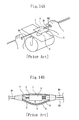
Japanese Patent Application Laid-Open No.4-334917 insulating cover 1 of required electric wires w1, w2 constructing the wire harness is peeled to expose thecores 2, the exposedcores 2 are connected to each other with thepressure terminal 3 to form the connectingpart 4, the connectingpart 4 is embedded in thesilicone 6 delivered to thewaterproof film 5, and thewaterproof film 5 and the auxiliarywaterproof film 7 are wrapped around the connectingpart 4. - When the
cores 2 are connected to each other with thepressure terminal 3 as described above, the number of electric wires which can be connected is not large. Thus even though thesilicone 6 has a high viscosity, waterproofness can be accomplished by filling thesilicone 6 between thecores 2.
But in forming the connecting part by connecting a large number of the cores to each other by ultrasonic welding, resistance welding, soldering or the like, thesilicone 6 cannot be filled in the entire spaces between thecores 2 when thesilicone 6 has a high viscosity. Therefore to fill thesilicone 6 in a large number of spaces between thecores 2, it is necessary to decrease the viscosity of thesilicone 6. When thesilicone 6 having a low viscosity is applied to and filled in the spaces between thecores 2, the above-described waterproof structure has a problem that thesilicone 6 drops or oozes from thefilms films oozed silicone 6 solidifies. But leaving thesilicone 6 until it solidifies makes the work efficiency low.
Patent document 1:Japanese Patent Application Laid-Open No.4-334917 - The present invention has been made in view of the above-described problems. Thus it is an object of the present invention to efficiently form a waterproof structure which securely waterproofs an electric wire connecting part by filling silicone between cores of the electric wire connecting part and prevents the silicone from dropping during a work and oozing after the work finishes.
- To solve the above-described problems, the present invention provides a waterproof structure of an electric wire connecting part in which insulating covers of electric wires are peeled; and exposed cores are connected to each other by welding, soldering or with a pressure terminal to form a connecting part; a foamed sheet impregnated with silicone is wrapped around the connecting part; and the silicone is filled in clearances between the connected cores to waterproof the electric wire connecting part.
- In the above-described construction, the connecting part of the electric wires is waterproofed by wrapping the foamed sheet impregnated with the silicone around the connecting part of the electric wires and filling the silicone in the clearances between the connected cores. In addition, the foamed sheet is capable of re-absorbing the silicone which drops or oozes therefrom in wrapping the foamed sheet around the connecting part. Therefore it is possible to efficiently perform a work of wrapping the foamed sheet around the electric wires by preventing the drop or oozing of the silicone.
Further because the foamed sheet prevents the drop or oozing of the silicone, it is possible to use the silicone having a low viscosity as a waterproof agent and thus fill the silicone in a large number of clearances between the cores by securely permeating the silicone thereinto. - Considering that the silicone permeates into the cores of the electric wires and is absorbed by the foamed sheet, it is preferable that the viscosity of the silicone is set to not more than 5 Pa·S.
- In the connecting part of the cores covered with the foamed sheet, an adhesive tape is wrapped around a peripheral surface of the foamed sheet.
Thereby the foamed sheet is held, with the foamed sheet wrapped around the connecting part of the electric wires. - It is possible that the connecting part of the cores covered with the foamed sheet is closely fitted inside a pair of semicircular annular members coupled to each other through a thin hinge portion at one end thereof and that other ends of the semicircular annular members are locked to each other.
In the above-described construction, the connecting part of the electric wires can be easily waterproofed by wrapping the foamed sheet impregnated with the silicone around the connecting part of the electric wires, locking a pair of the semicircular annular members to each other, and mounting a sheath on the connecting part of the electric wires. - Silicone which has oozed from the foamed sheet forms a silicone-filled portion at a contact portion between the connecting part of the cores and the foamed sheet.
In the above-described construction, the silicone-filled portion formed by the oozing of the silicone from the foamed sheet at the contact portion between the connecting part of the cores and the foamed sheet is capable of waterproofing the connecting part of the cores. In the construction in which the silicone is not permeated into the peripheral side, of the foamed sheet, which does not contact the connecting part of the cores, the peripheral side of the foamed sheet efficiently re-absorbs the silicone which drops or oozes therefrom when the foamed sheet is wrapped around the connecting part, thus preventing the drop and oozing of the silicone therefrom. - It is preferable that the foamed sheet consists of an interconnecting cellular foamed material.
In this construction, the silicone which has sufficiently permeated into the foamed sheet oozes to form the silicone-filled portion. In addition, it is possible to efficiently absorb the silicone that has oozed outside. - It is preferable that a concavity and a convexity fitting in each other are formed at opposite sides of a surface of the foamed sheet in a direction in which the foamed sheet is wrapped around the connecting part of the cores.
Owing to the above-described configuration of the foamed sheet, when the adhesive tape and the foamed sheet are folded at the position where the electric wires are disposed, with the foamed sheet impregnated with the silicone disposed on the adhesive tape and with the connecting part of the cores disposed on the foamed sheet, the surface of the concavity and that of the convexity fitted in the concavity adhere to the adhesive tape. Thus when the concavity and the convexity are further folded and wrapped around the connecting part of the cores, the foamed sheet does not shift because both surfaces of the concavity and that of the convexity are adhered to the adhesive tape. Therefore it is easy to accomplish a wrapping work which is performed by re-folding the concavity and the convexity.
The foamed sheet is not overlapped at the position where the foamed sheet is re-folded. Because only one sheet of the foamed sheet is folded, a large force is unnecessary in folding it. - It is possible that the foamed sheet which is rectangular is disposed, wound, and portions thereof are laminated on each other, with the foamed sheet inclined with respect to an axial direction of the connecting part of the cores and that the rectangular adhesive tape disposed in parallel with the axial direction of the connecting part of the cores is wrapped around a peripheral surface of the foamed sheet.
In the above-described construction, when the adhesive tape and the foamed sheet are folded at the position where the electric wires are disposed, portions of the foamed sheet overlap on each other, and portions of the adhesive tape are adhered to each other at both sides of the foamed sheet.
Thus when the overlapped side is further folded and wound, the foamed sheet does not shift. Therefore it is easy to accomplish a wrapping work which is performed by re-folding the overlapped side.
The foamed sheet is disposed by inclining it with respect to the axial direction of the connecting part, at the position where the foamed sheet is folded and overlapped, the foamed sheet is short in the axial length of the connecting part. Therefore a large force is not required to fold the foamed sheet. - The present invention provides a method of waterproofing an electric wire connecting part including the steps of forming a connecting part of cores by peeling insulating covers of a plurality of electric wires and connecting exposed cores to each other by welding, soldering or with a pressure terminal; and
disposing a foamed sheet impregnated with silicone on an adhesive tape, disposing the connecting part of the cores on the foamed sheet, folding the adhesive tape and the foamed sheet and overlapping the foamed sheet on the adhesive tape at a position where the electric wires are disposed, and folding and winding an overlapped side. - Particularly, a concavity and a convexity fitting in each other are formed at opposite sides of a surface of the foamed sheet in a direction in which the foamed sheet is wrapped around the connecting part of the cores or the foamed sheet which is rectangular is disposed, with the foamed sheet inclined with respect to the axial direction of the connecting part of the cores. Thereby as described above, the foamed sheet and the adhesive sheet can be re-folded easily at the position where the foamed sheet and the adhesive sheet are folded and overlapped on each other.
- As described above, according to the present invention, waterproofing is performed by wrapping the foamed sheet impregnated with the silicone around the connecting part of the electric wires and filling the silicone in the clearances between the cores. In addition, the foamed sheet is capable of absorbing the silicone which has dropped or oozed therefrom. Therefore it is unnecessary to leave the silicone until it solidifies and possible to efficiently perform a work of wrapping the foamed sheet around the electric wires.
Further because the foamed sheet prevents the drop or oozing of the silicone, it is possible to use the silicone having a low viscosity as a waterproof agent and thus fill the silicone in a large number of clearances between the cores by securely allowing the silicone to permeate thereinto. -
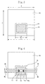
- Fig. 1 shows a first embodiment of the present invention, in which (A) is a perspective view, and (B) is a sectional view taken along a line A-A.
- Fig. 2 shows a connecting part of electric wires.
- Fig. 3 shows a state in which a foamed sheet is placed on an adhesive tape.
- Fig. 4 shows a state in which a connecting part of the electric wires is placed on the foamed sheet.
- Figs. 5A and 5B show a method of forming a waterproof structure of the first embodiment.
- Fig. 6 shows a second embodiment of the present invention, showing a state in which a foamed sheet is adhered to an adhesive tape.
- Fig. 7 shows the process of forming a waterproof structure of the second embodiment.
- Fig. 8 is a plan view of a foamed sheet of a first modification of the second embodiment.
- Fig. 9 shows the process of forming a waterproof structure of the first modification of the second embodiment.
- Fig. 10 is a plan view of a foamed sheet of a second modification of the second embodiment.
- Fig. 11 shows the process of forming a waterproof structure of a second modification of the second embodiment.
- Fig. 12 is a perspective view of a sheath for use in a third embodiment of the present invention.
- Figs. 13(A), (B), and (C) show a method of forming a waterproof structure of the third embodiment.
- Figs. 14(A) and (B) show a conventional art.
-
- 10:
- waterproof structure
- 11:
- insulating cover
- 12:
- core
- 13:
- connecting part
- 14:
- silicone
- 15:
- foamed sheet
- 15a:
- concavity
- 15b:
- convexity
- 16:
- adhesive tape
- 20:
- sheath
- 20a:
- semicircular annular member
- 30:
- jig
- The embodiments of the present invention will be described below with reference to the drawings.
Figs. 1 through 5 show a first embodiment of the present invention.Cores 12 exposed by peeling insulatingcovers 11 of electric wires w1, w2 at a central position of each of the electric wires w1, w2 are welded by ultrasonic wave to form a connectingpart 13. The connectingpart 13, the exposedcores 12 disposed at both sides of the connectingpart 13, and a tip portion of each of the insulating covers 11 continuous with thecores 12 respectively are embedded insilicone 14. A foamedsheet 15 and anadhesive tape 16 are wrapped around thesilicone 14 to surround thesilicone 14 completely to form awaterproof structure 10. - As shown in Fig. 3, the foamed
sheet 15 and theadhesive tape 16 are both rectangular before they are wrapped around the electric wires w1, w2. A length L1 of theadhesive tape 16 in an axial direction X of the connectingpart 13 is set to 65mm. A length L2 of the foamedsheet 15 in the axial direction X of the connectingpart 13 is set to not more than 80% of the length L1 and set to 46% of the length L1, namely, 30mm in the first embodiment. The foamedsheet 15 is adhered to theadhesive tape 16 at a central position thereof in the axial direction X of the connectingpart 13, with the foamedsheet 15 parallel with theadhesive tape 16. Anadhesive surface 16a of theadhesive tape 16 is exposed at both sides of the foamedsheet 15 to allow theadhesive surface 16a to be adhesive to the electric wires w1, w2 to be placed thereon. The length of the foamedsheet 15 in an electric wire-wrapping direction Y is set longer than the length of the periphery of the electric wires around which the foamedsheet 15 is wrapped to allow the periphery of the electric wires w1, w2 to be wrapped with at least one turn of the foamedsheet 15. - The foamed
sheet 15 is composed of an interconnecting cellular foamed material. Thesilicone 14 is applied to the center of the foamedsheet 15 to impregnate the foamedsheet 15 with thesilicone 14. On the other hand, thesilicone 14 is not applied to the peripheral side of the foamedsheet 15.
The viscosity of thesilicone 14 is set to a low viscosity of 5 Pa-S. The application amount of thesilicone 14 is shown by (1-n) × (a×h) ×s (g) (n is the density (g/cm3) of the foamed sheet, a is the surface area (cm2) of the foamed sheet, h is the thickness (cm) of the foamed sheet, and s is the specific gravity of the silicone). In the first embodiment, n=0.064(g/cm3), a=9 (cm2), h=0.2(cm), and s=1.01(g). The application amount of thesilicone 14 is set to 1.7g. - The method of forming the
waterproof structure 10 of the connectingpart 13 is described below.
Initially as shown in Fig. 2, thecores 12 are exposed by peeling the insulating covers 11 at the required central position of the electric wires w1, w2 at which they are connected to each other. The exposedcores 12 are welded to each other by a ultrasonic wave to form the connectingpart 13 where the electric wires w1, w2 are connected to each other. - As shown in Fig. 3, after the foamed
sheet 15 is stuck to theadhesive surface 16a of theadhesive tape 16, thesilicone 14 is applied to the foamedsheet 15 and permeated thereinto. - The connecting
part 13 of the electric wires w1, w2 is placed at the central position of the foamedsheet 15.
Thereafter as shown in Fig. 5(A), the foamedsheet 15 and theadhesive tape 16 are folded at the position of the foamedsheet 15 where the electric wires w1, w2 are disposed, both ends of the foamedsheet 15 are overlapped on each other, and the opposedadhesive surfaces 16a of theadhesive tape 16 are adhered to each other. At this time, thesilicone 14 which has permeated into the foamedsheet 15 oozes to form a silicone-filled portion, with thesilicone 14 penetrating between thecores 12 of the electric wires w1, w2. When thesilicone 14 which has oozed from the foamedsheet 15 flows toward both sides of the connectingpart 13 in its axial direction, the peripheral portion of the foamedsheet 15 re-absorbs thesilicone 14, thus preventing thesilicone 14 from oozing from the foamedsheet 15. - Finally as shown in Fig. 5B, the foamed
sheet 15 is further folded by a tape-wrapping machine (not shown) at the position thereof where both ends have been overlapped on each other. Thereafter theadhesive surface 16a of theadhesive tape 16 is wrapped around the peripheral surface of theadhesive tape 16 and adhered thereto. - In the above-described construction, because the
silicone 14 having a low viscosity is used to waterproof the connectingpart 13 formed between the electric wires w1 and w2, thesilicone 14 can be penetrated between thecores 12 of the electric wires w1, w2. Thus the waterproofness can be secured. Further thesilicone 14 having a low viscosity is permeated into the foamedsheet 15. Thus when the foamedsheet 15 is wrapped around the electric wires w1, w2, thesilicone 14 oozes from the foamedsheet 15 and can be permeated between thecores 12. Thesilicone 14 oozing from the foamedsheet 15 can be re-absorbed by the foamedsheet 15. Therefore it is possible to efficiently perform a work of wrapping the foamedsheet 15 around the electric wires w1, w2.
Because the foamedsheet 15 is capable of absorbing the silicone oozing from the foamedsheet 15, it is only necessary to wrap the foamedsheet 15 to the tip portion of the insulatingcover 11 continuous with the exposedcores 12. Thus it is possible to decrease the wrapping range of the foamedsheet 15. Thereby the electric wires are not made large.
Although in the first embodiment, two electric wires are spliced to each other, the waterproof structure of the first embodiment may be formed for a connection part at which not less than three electric wires are spliced to each other.
Further the waterproof structure of the first embodiment may be formed for not only the connecting part formed at the central position of the electric wires, but also for the connecting part formed at the terminal of electric wires.
The connecting part of the cores may be formed by connecting the cores to each other not only by welding but also by soldering or with a pressure terminal. - Figs. 6 and 7 show the second embodiment of the present invention. The foamed
sheet 15 similar to that of the first embodiment is stuck to theadhesive tape 16 by rotating the foamedsheet 15 45 degrees. The foamedsheet 15 is disposed at an inclination of 45 degrees to the axial direction of the connectingpart 13, whereas theadhesive tape 16 is disposed in parallel with the axial direction of the connectingpart 13. The distance between a corner of the foamedsheet 15 closest to the periphery of theadhesive tape 16 and the periphery of theadhesive tape 16 is set to 5mm. - The electric wires w1, w2 having the connecting
part 13 are placed on diagonal lines of the foamedsheet 15. Similarly to the first embodiment, as shown in Fig. 7, the foamedsheet 15 and theadhesive tape 16 are folded at the position where the electric wires w1, w2 are disposed, the foamedsheet 15 is overlapped, and theadhesive surfaces 16a of theadhesive tape 16 are laminated on each other. Finally by using a tape-wrapping machine, the foamedsheet 15 and theadhesive tape 16 are further folded at abroken line 1 drawn at the overlapped portion of the foamedsheet 15 to wrap theadhesive surface 16a of theadhesive tape 16 around the peripheral surface of theadhesive tape 16. - In the above-described construction, because an axial length L3 of the connecting part on the
broken line 1 along which the foamedsheet 15 is folded by using the tape-wrapping machine is short, the foamedsheet 15 can be folded at a smaller torque than the torque in the first embodiment. Because an adhesive force is increased by increasing an area of contact S between theadhesive tape 16 at both sides of the folded foamedsheet 15, the foamedsheet 15 does not shift in the axial direction of the connecting part. Thus the foamedsheet 15 can be easily wrapped around the electric wires w1, w2. - Figs. 8 and 9 show a first modification of the second embodiment in which the configuration of the foamed
sheet 15 is different from that of the foamedsheet 15 of the second embodiment. Atriangular concavity 15a is formed at one side of the foamedsheet 15, and atriangular convexity 15b is formed at the opposed other side thereof.
Theconcavity 15a of the foamedsheet 15 and the convexity 15b thereof are adhered to theadhesive tape 16, with theconcavity 15a and theconvexity 15b opposed to each other in an electric wires-wrapping direction. The foamedsheet 15 and theadhesive tape 16 are folded at a position where the electric wires w1, w2 are disposed, with the electric wires w1, w2 placed at positions where the electric wires w1, w2 pass through the center of the foamedsheet 15. As a result, a state shown in Fig. 9 is obtained. Because the foamedsheet 15 is not overlapped on thebroken line 1 at which the foamedsheet 15 is folded by the tape-wrapping machine, the foamedsheet 15 can be folded at a small torque. Both surfaces of the foamedsheet 15 are adhered to theadhesive tape 16 on thebroken line 1, the foamedsheet 15 does not shift in the axial direction of the connecting part. Thus the foamedsheet 15 can be easily wrapped around the electric wires w1, w2. - Figs. 10 and 11 show a second modification of the second embodiment in which a
quadrangular concavity 15a is formed at one side of the foamedsheet 15, and aquadrangular convexity 15b is formed at the opposed other side thereof. When the foamedsheet 15 and theadhesive tape 16 are folded at a position where the electric wires w1, w2 are disposed, a state shown in Fig. 11 is obtained. The foamedsheet 15 is not overlapped on thebroken line 1 at which the foamedsheet 15 is folded by the tape-wrapping machine. Therefore in the second modification, it is possible to obtain an effect similar to that of the first modification. - Figs. 12 and 13 show a third embodiment of the present invention. In the third embodiment, the adhesive tape is not used, but a
sheath 20, made of resin, in which ends of a pair of semicircularannular members 20a are coupled to each other with athin hinge portion 20b is used. At the other end of the two semicircularannular members 20a, a lockingportion 20c and a to-be-locked portion 20d are formed at corresponding positions. Arib 20e for preventing slip of the foamedsheet 15 is formed on an inner peripheral surface of each semicircularannular member 20a at positions in the vicinity of both ends of each semicircularannular members 20a in its longitudinal direction. Similarly to the first embodiment, a waterproof structure 10' is formed by accommodating electric wires inside thesheath 20, with the foamedsheet 15 into which thesilicone 14 has been permeated wrapped around the electric wires, locking a pair of the semicircularannular members 20a to each other, and mounting thesheath 20 on the electric wires. - In forming the waterproof structure 10', a
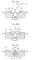
jig 30 is used. As shown in Fig. 13, thejig 30 is provided with twotemporary positioning concavities 30a for temporarily positioning thesheath 20 on the outer surface of thejig 30 and a lockingconcavity 30b for locking a pair of the semicircularannular members 20a to each other by pressing thesheath 20 into the lockingconcavity 30b. The lockingconcavity 30b is disposed between thetemporary positioning concavities 30a and below thetemporary positioning concavities 30a. - The method of forming the waterproof structure 10' is described below.
Initially as shown in Fig. 13(A), thesheath 20 is placed in thetemporary positioning concavity 30a of thejig 30, with a pair of the semicircularannular members 20a open.
Thereafter as shown in Fig. 13(B), the foamedsheet 15 is placed on an upper surface of thesheath 20, and thesilicone 14 is delivered to the foamedsheet 15 and permeated thereinto.
Finally as shown in Fig. 13(C), with the axial direction of the connectingpart 13 of thecores 12 in conformity to the longitudinal direction of the semicircularannular member 20a, the connectingpart 13 is placed on the foamedsheet 15. When the connectingpart 13 is pressed downward, thesheath 20 is pressed into the lockingconcavity 30b, and the two semicircularannular members 20a are bent in a direction in which the semicircularannular members 20a approach to each other on thethin hinge portion 20b and are locked to each other. - By carrying out the above-described method, the waterproof structure 10' can be formed on the connecting
part 13.
In the above-described method, the electric wires are merely pressed into the jig. Therefore without skill, everybody can easily form the waterproof structure 10'. Further the method eliminates the need for using the tape-wrapping machine. Thus it is possible to reduce the cost of forming the waterproof structure 10'.
Further by visually checking whether a pair of the semicircularannular members 20a has been locked to each other, it is possible to detect whether the waterproof structure has been formed. Furthermore by forming thesheath 20 from a transparent resin, it is possible to visually check a state inside thesheath 20.
Claims (10)
- A waterproof structure of an electric wire connecting part in which insulating covers of electric wires are peeled; and exposed cores are connected to each other by welding, soldering or with a pressure terminal to form a connecting part; a foamed sheet impregnated with silicone is wrapped around said connecting part; and said silicone is filled in clearances between said connected cores to waterproof said electric wire connecting part.
- The waterproof structure of an electric wire connecting part according to claim 1, wherein in said connecting part of said cores covered with said foamed sheet, an adhesive tape is wrapped around a peripheral surface of said foamed sheet.
- The waterproof structure of an electric wire connecting part according to claim 1, wherein said connecting part of said cores covered with said foamed sheet is closely fitted inside a pair of semicircular annular members coupled to each other through a thin hinge portion at one end thereof; and other ends of said semicircular annular members are locked to each other.
- The waterproof structure of an electric wire connecting part according to any one of claims 1 through 3, wherein silicone which has oozed from said foamed sheet forms a silicone-filled portion at a contact portion between said connecting part of said cores and said foamed sheet.
- The waterproof structure of an electric wire connecting part according to any one of claims 1 through 4, wherein said foamed sheet consists of an interconnecting cellular foamed material.
- The waterproof structure of an electric wire connecting part according to any one of claims 1 through 5, wherein a concavity and a convexity fitting in each other are formed at opposite sides of a surface of said foamed sheet in a direction in which said foamed sheet is wrapped around said connecting part of said cores.
- The waterproof structure of an electric wire connecting part according to any one of claims 2, 4, and 5, wherein said foamed sheet which is rectangular is disposed, wound, and portions thereof are laminated on each other, with said foamed sheet inclined with respect to an axial direction of said connecting part of said cores; and said rectangular adhesive tape disposed in parallel with said axial direction of said connecting part of said cores is wrapped around a peripheral surface of said foamed sheet.
- A method of waterproofing an electric wire connecting part, comprising the steps of:forming a connecting part of cores by peeling insulating covers of a plurality of electric wires and connecting exposed cores to each other by welding, soldering or with a pressure terminal; anddisposing a foamed sheet impregnated with silicone on an adhesive tape, disposing said connecting part of said cores on said foamed sheet, folding said adhesive tape and said foamed sheet and overlapping said foamed sheet on said adhesive tape at a position where said electric wires are disposed, and folding and winding an overlapped side.
- The method of waterproofing an electric wire connecting part according to claim 8, wherein a concavity and a convexity fitting in each other are formed at opposite sides of a surface of said foamed sheet in a direction in which said foamed sheet is wrapped around said connecting part of said cores; and both surfaces of said concavity and both surfaces of said convexity fitted in said concavity are adhered to said adhesive tape when said adhesive tape and said foamed sheet are folded at said position where said electric wires are disposed; and said concavity and said convexity are further folded and wound.
- The method of waterproofing an electric wire connecting part according to claim 8, wherein said foamed sheet which is rectangular is disposed, with said foamed sheet inclined with respect to an axial direction of said connecting part of said cores; said adhesive tape and said foamed sheet are folded at said position where said electric wires are disposed; portions of said foamed sheet are overlapped on each other; portions of said adhesive tape are laminated on each other at both sides of said foamed sheet; and an overlapped side is further folded and wound.
Applications Claiming Priority (2)
| Application Number | Priority Date | Filing Date | Title |
|---|---|---|---|
| JP2004130330 | 2004-04-26 | ||
| PCT/JP2005/003746 WO2005104302A1 (en) | 2004-04-26 | 2005-03-04 | Waterproof structure and waterproof method for wire connecting part |
Publications (3)
| Publication Number | Publication Date |
|---|---|
| EP1744403A1 true EP1744403A1 (en) | 2007-01-17 |
| EP1744403A4 EP1744403A4 (en) | 2008-03-12 |
| EP1744403B1 EP1744403B1 (en) | 2011-06-29 |
Family
ID=35197309
Family Applications (1)
| Application Number | Title | Priority Date | Filing Date |
|---|---|---|---|
| EP05720018A Expired - Lifetime EP1744403B1 (en) | 2004-04-26 | 2005-03-04 | Waterproof structure and waterproof method for wire connecting part |
Country Status (5)
| Country | Link |
|---|---|
| US (1) | US7572979B2 (en) |
| EP (1) | EP1744403B1 (en) |
| JP (1) | JP4677985B2 (en) |
| CN (1) | CN100481618C (en) |
| WO (1) | WO2005104302A1 (en) |
Cited By (5)
| Publication number | Priority date | Publication date | Assignee | Title |
|---|---|---|---|---|
| EP2161787A4 (en) * | 2007-06-21 | 2013-09-18 | Sumitomo Wiring Systems | Method of waterproofing splice area and wiring structure for automobile wire harness with splice area |
| EP2033287A4 (en) * | 2006-06-07 | 2016-11-16 | 3M Innovative Properties Co | Sealing apparatus |
| DE112011103304B4 (en) * | 2010-09-30 | 2017-03-09 | Autonetworks Technologies, Ltd. | A method of making a waterproof intermediate spliced portion of wires and waterproof inter-spliced unit of wires |
| EP3477806A1 (en) * | 2017-10-30 | 2019-05-01 | Komax Holding Ag | Method for connecting a first cable with a second cable, cable assembly and cable connecting apparatus for connecting a first cable with a second cable |
| NL2020794B1 (en) * | 2018-04-19 | 2019-10-28 | Gebr Geers B V | ELECTRIC MAIN WIRE WITH BRANCH |
Families Citing this family (30)
| Publication number | Priority date | Publication date | Assignee | Title |
|---|---|---|---|---|
| JP4996205B2 (en) * | 2006-11-08 | 2012-08-08 | 株式会社オートネットワーク技術研究所 | Method for water stop treatment of electric wires |
| JP5151701B2 (en) * | 2008-06-03 | 2013-02-27 | 住友電装株式会社 | Drainage structure of wire harness |
| KR100874687B1 (en) * | 2008-08-29 | 2008-12-18 | 안승범 | Double watertight structure live part protection device of power system |
| US8740223B1 (en) * | 2009-05-07 | 2014-06-03 | Dan Alpi | Method and apparatus for sealing connections between electrical power cords |
| US8985586B1 (en) * | 2009-05-07 | 2015-03-24 | Dan Alpi | Method and apparatus for sealing connections between electrical extension cords |
| JP5495203B2 (en) * | 2009-09-24 | 2014-05-21 | 矢崎総業株式会社 | Waterproofing method for crimping part |
| JP4848040B2 (en) * | 2010-04-08 | 2011-12-28 | 株式会社オートネットワーク技術研究所 | Terminal structure of wire harness |
| JP5740146B2 (en) * | 2010-12-10 | 2015-06-24 | 矢崎総業株式会社 | Wire harness |
| US20120261156A1 (en) * | 2011-04-12 | 2012-10-18 | 3M Innovative Properties Company | Protection device for a cable connection |
| JP5889047B2 (en) * | 2012-03-08 | 2016-03-22 | スリーエム イノベイティブ プロパティズ カンパニー | Insulating waterproof member and insulating waterproof method |
| EP2731203B1 (en) * | 2012-08-29 | 2018-05-09 | Nexans | Method for moisture-proof covering of a junction between an electric conductor and a contact element |
| CN103259105A (en) * | 2012-09-25 | 2013-08-21 | 优光环保材料(上海)有限公司 | Wiring protection box and using method thereof |
| JP2014128136A (en) * | 2012-12-27 | 2014-07-07 | Viscas Corp | Connection structure of power cable |
| JP2014130709A (en) * | 2012-12-28 | 2014-07-10 | 3M Innovative Properties Co | Waterproofing member and waterproofing method |
| JP5657179B1 (en) * | 2013-02-23 | 2015-01-21 | 古河電気工業株式会社 | Connection structure, connector, method for manufacturing connection structure, electric wire connection structure, and tubular terminal |
| JP5974963B2 (en) * | 2013-04-10 | 2016-08-23 | 住友電装株式会社 | Terminal concentration splice of wire group |
| JP6198934B2 (en) * | 2013-05-02 | 2017-09-20 | ジェンサーム ゲーエムベーハー | Liquid-resistant heating element |
| US9455063B2 (en) * | 2013-09-26 | 2016-09-27 | Apple Inc. | Cable structures with localized foam strain reliefs and systems and methods for making the same |
| JP6123699B2 (en) * | 2014-02-20 | 2017-05-10 | 住友電装株式会社 | Sheet winding apparatus and method of manufacturing electric wire module including splice part |
| JP6172127B2 (en) * | 2014-11-28 | 2017-08-02 | 株式会社オートネットワーク技術研究所 | Wire Harness |
| JP6323317B2 (en) * | 2014-12-09 | 2018-05-16 | 株式会社オートネットワーク技術研究所 | Electric wire with terminal |
| EP3295531A1 (en) * | 2015-05-15 | 2018-03-21 | 3M Innovative Properties Company | Weather-proofing solution for a cable connection |
| JP6357448B2 (en) * | 2015-07-09 | 2018-07-11 | 矢崎総業株式会社 | Electric wire with connector and method for manufacturing electric wire with connector |
| JP6439742B2 (en) * | 2016-04-27 | 2018-12-19 | 株式会社オートネットワーク技術研究所 | Wire Harness |
| JP6439743B2 (en) * | 2016-04-27 | 2018-12-19 | 株式会社オートネットワーク技術研究所 | Wire Harness |
| DE102016219374B4 (en) * | 2016-10-06 | 2018-06-14 | Siemens Aktiengesellschaft | Long-term stable and cohesive current path connection for low-voltage, medium-voltage and / or high-voltage systems or switching devices by means of nanomaterials |
| JP7028098B2 (en) * | 2018-08-01 | 2022-03-02 | 株式会社オートネットワーク技術研究所 | Fixed structure of splice part |
| JP7390132B2 (en) * | 2019-08-21 | 2023-12-01 | 株式会社オートネットワーク技術研究所 | Wire Harness |
| JP7298388B2 (en) * | 2019-08-21 | 2023-06-27 | 株式会社オートネットワーク技術研究所 | Wire Harness |
| US11271381B2 (en) * | 2019-09-20 | 2022-03-08 | Baker Hughes Oilfield Operations Llc | Systems and methods for subsea wiring splices |
Family Cites Families (24)
| Publication number | Priority date | Publication date | Assignee | Title |
|---|---|---|---|---|
| US3619481A (en) * | 1969-10-13 | 1971-11-09 | Smith Schreyer & Assoc Inc | Enclosure for an electrical cable splice |
| US3879575A (en) * | 1974-02-21 | 1975-04-22 | Bell Telephone Labor Inc | Encapsulating compound and closure |
| JPS5820475A (en) | 1981-07-30 | 1983-02-05 | Oki Electric Ind Co Ltd | Serial printing type thermal printer |
| JPS5820475U (en) * | 1981-07-31 | 1983-02-08 | 日本安全産業株式会社 | Insulation protection cover for insulated wire connections |
| US4721832A (en) * | 1985-05-02 | 1988-01-26 | Raychem Corporation | Electrical connection sealing device |
| US4647717A (en) * | 1985-05-02 | 1987-03-03 | Raychem Corp. | Gel filled container |
| US4751350A (en) * | 1986-11-06 | 1988-06-14 | Raychem Corporation | Sealing device and retention member therefor |
| US4888070A (en) * | 1987-12-01 | 1989-12-19 | Raychem Corporation | Environmental sealing of a substrate |
| US4863535A (en) | 1987-12-09 | 1989-09-05 | Minnesota Mining And Manufacturing Company | Electrical environmental sealant and method |
| US4849580A (en) | 1988-02-11 | 1989-07-18 | Minnesota Mining And Manufacturing Company | Environmental protection closure for wire splices; and method |
| JPH045062A (en) | 1990-04-23 | 1992-01-09 | Pfu Ltd | Printer control system |
| JP2593163Y2 (en) * | 1990-04-26 | 1999-04-05 | 住友電装 株式会社 | Waterproof structure of wire connection |
| JP2747679B2 (en) | 1991-04-24 | 1998-05-06 | 日東電工株式会社 | Water-tightening method of wire branch connection |
| JP2936795B2 (en) | 1991-05-09 | 1999-08-23 | 住友電装株式会社 | Waterproofing method of wire connection |
| US5399810A (en) * | 1992-11-03 | 1995-03-21 | Three Bond Co., Ltd. | Means for coating connecting portions of electrical wires |
| JP2894581B2 (en) | 1993-05-24 | 1999-05-24 | 矢崎総業株式会社 | Waterproof structure of wire harness |
| JPH09185967A (en) | 1995-12-28 | 1997-07-15 | Yazaki Corp | Method for manufacturing waterproof joint part and waterproof joint structure |
| JP3488080B2 (en) | 1998-03-27 | 2004-01-19 | 矢崎総業株式会社 | Flat harness seat |
| JPH11297382A (en) | 1998-04-10 | 1999-10-29 | Yazaki Corp | Protection sheet for wire connection |
| US6730847B1 (en) * | 2000-03-31 | 2004-05-04 | Tyco Electronics Corporation | Electrical connection protector kit and method for using the same |
| JP4916056B2 (en) * | 2001-06-11 | 2012-04-11 | 矢崎総業株式会社 | Manufacturing method of waterproof wire harness |
| US7253362B1 (en) * | 2006-06-07 | 2007-08-07 | 3M Innovative Properties Company | Closure with wrapped cable |
| US7307219B1 (en) * | 2006-06-07 | 2007-12-11 | 3M Innovative Properties Company | Closure housing for sealing |
| US7304244B1 (en) * | 2006-06-07 | 2007-12-04 | 3M Innovative Properties Company | Method of making closure housing for sealing |
-
2005
- 2005-03-04 CN CNB200580019354XA patent/CN100481618C/en not_active Expired - Lifetime
- 2005-03-04 EP EP05720018A patent/EP1744403B1/en not_active Expired - Lifetime
- 2005-03-04 JP JP2006512482A patent/JP4677985B2/en not_active Expired - Lifetime
- 2005-03-04 US US11/547,613 patent/US7572979B2/en not_active Expired - Lifetime
- 2005-03-04 WO PCT/JP2005/003746 patent/WO2005104302A1/en not_active Ceased
Cited By (8)
| Publication number | Priority date | Publication date | Assignee | Title |
|---|---|---|---|---|
| EP2033287A4 (en) * | 2006-06-07 | 2016-11-16 | 3M Innovative Properties Co | Sealing apparatus |
| EP2161787A4 (en) * | 2007-06-21 | 2013-09-18 | Sumitomo Wiring Systems | Method of waterproofing splice area and wiring structure for automobile wire harness with splice area |
| DE112011103304B4 (en) * | 2010-09-30 | 2017-03-09 | Autonetworks Technologies, Ltd. | A method of making a waterproof intermediate spliced portion of wires and waterproof inter-spliced unit of wires |
| EP3477806A1 (en) * | 2017-10-30 | 2019-05-01 | Komax Holding Ag | Method for connecting a first cable with a second cable, cable assembly and cable connecting apparatus for connecting a first cable with a second cable |
| US11404855B2 (en) | 2017-10-30 | 2022-08-02 | Komax Holding Ag | Method of connecting a first cable to a second cable, cable arrangement, and cable connection device for connecting a first cable to a second cable |
| NL2020794B1 (en) * | 2018-04-19 | 2019-10-28 | Gebr Geers B V | ELECTRIC MAIN WIRE WITH BRANCH |
| BE1026189A1 (en) | 2018-04-19 | 2019-10-30 | Gebr Geers B V | ELECTRIC MAIN WIRE WITH BRANCH |
| BE1026189B1 (en) * | 2018-04-19 | 2020-04-06 | Gebr Geers B V | ELECTRIC MAIN PIPE WITH BRANCH |
Also Published As
| Publication number | Publication date |
|---|---|
| JPWO2005104302A1 (en) | 2008-07-31 |
| CN1969427A (en) | 2007-05-23 |
| JP4677985B2 (en) | 2011-04-27 |
| EP1744403B1 (en) | 2011-06-29 |
| US20070209821A1 (en) | 2007-09-13 |
| EP1744403A4 (en) | 2008-03-12 |
| CN100481618C (en) | 2009-04-22 |
| US7572979B2 (en) | 2009-08-11 |
| WO2005104302A1 (en) | 2005-11-03 |
Similar Documents
| Publication | Publication Date | Title |
|---|---|---|
| EP1744403B1 (en) | Waterproof structure and waterproof method for wire connecting part | |
| US4466843A (en) | Protection of cable splice | |
| US20140284099A1 (en) | Water stopping structure of core wires and water stopping method of core wires | |
| JPH11233175A (en) | Waterproof structure of wire end and method of forming waterproof structure | |
| US5940962A (en) | Wire harness bundling method | |
| GB2282922A (en) | Insulating electrical connection | |
| EP2161787B1 (en) | Method of waterproofing splice area and wiring structure for automobile wire harness with splice area | |
| US20050133247A1 (en) | Protector cover for terminal group | |
| JP3629989B2 (en) | Grommet line sealing method and grommet line sealing structure | |
| JP2012204016A (en) | Water cut-off method for electric wire and water cut-off structure for electric wire | |
| JP2004072943A (en) | Water cut-off structure for earth wire | |
| JP2001231132A (en) | Wire harness waterproof structure for grommet | |
| JP2007141517A (en) | Waterproofing method for wire harness | |
| US3393796A (en) | Packaged article and method of packaging | |
| JP2000188018A (en) | Wire connection structure in wire harness | |
| US6906263B2 (en) | Crossing-wire fixing structure | |
| JP2001057252A (en) | Waterproof splice structure and method for forming the waterproof splice structure | |
| JP2006318716A (en) | Waterproof structure of electric wire intermediate joint | |
| JPH0670426U (en) | Waterproof wire harness | |
| JP5264130B2 (en) | Line water stop method | |
| JP2013116031A (en) | Waterproof rubber, method of manufacturing waterproof rubber, and waterproof insulation processing method using waterproof insulation rubber | |
| JPH09224324A (en) | How to connect wires | |
| JPH0562961U (en) | Cord connection structure | |
| JPH1198673A (en) | Waterproof sheet and waterproof structure for wire joints | |
| JPH09185967A (en) | Method for manufacturing waterproof joint part and waterproof joint structure |
Legal Events
| Date | Code | Title | Description |
|---|---|---|---|
| PUAI | Public reference made under article 153(3) epc to a published international application that has entered the european phase |
Free format text: ORIGINAL CODE: 0009012 |
|
| 17P | Request for examination filed |
Effective date: 20061127 |
|
| AK | Designated contracting states |
Kind code of ref document: A1 Designated state(s): DE FR GB IT |
|
| DAX | Request for extension of the european patent (deleted) | ||
| RBV | Designated contracting states (corrected) |
Designated state(s): DE FR GB IT |
|
| A4 | Supplementary search report drawn up and despatched |
Effective date: 20080213 |
|
| 17Q | First examination report despatched |
Effective date: 20101018 |
|
| GRAP | Despatch of communication of intention to grant a patent |
Free format text: ORIGINAL CODE: EPIDOSNIGR1 |
|
| GRAS | Grant fee paid |
Free format text: ORIGINAL CODE: EPIDOSNIGR3 |
|
| GRAA | (expected) grant |
Free format text: ORIGINAL CODE: 0009210 |
|
| AK | Designated contracting states |
Kind code of ref document: B1 Designated state(s): DE FR GB IT |
|
| REG | Reference to a national code |
Ref country code: GB Ref legal event code: FG4D |
|
| REG | Reference to a national code |
Ref country code: DE Ref legal event code: R096 Ref document number: 602005028743 Country of ref document: DE Effective date: 20110818 |
|
| PLBE | No opposition filed within time limit |
Free format text: ORIGINAL CODE: 0009261 |
|
| STAA | Information on the status of an ep patent application or granted ep patent |
Free format text: STATUS: NO OPPOSITION FILED WITHIN TIME LIMIT |
|
| 26N | No opposition filed |
Effective date: 20120330 |
|
| REG | Reference to a national code |
Ref country code: DE Ref legal event code: R097 Ref document number: 602005028743 Country of ref document: DE Effective date: 20120330 |
|
| REG | Reference to a national code |
Ref country code: FR Ref legal event code: PLFP Year of fee payment: 12 |
|
| REG | Reference to a national code |
Ref country code: FR Ref legal event code: PLFP Year of fee payment: 13 |
|
| REG | Reference to a national code |
Ref country code: DE Ref legal event code: R084 Ref document number: 602005028743 Country of ref document: DE |
|
| REG | Reference to a national code |
Ref country code: GB Ref legal event code: 746 Effective date: 20170622 |
|
| REG | Reference to a national code |
Ref country code: FR Ref legal event code: PLFP Year of fee payment: 14 |
|
| PGFP | Annual fee paid to national office [announced via postgrant information from national office to epo] |
Ref country code: IT Payment date: 20210211 Year of fee payment: 17 |
|
| PGFP | Annual fee paid to national office [announced via postgrant information from national office to epo] |
Ref country code: GB Payment date: 20210225 Year of fee payment: 17 Ref country code: DE Payment date: 20210216 Year of fee payment: 17 |
|
| REG | Reference to a national code |
Ref country code: DE Ref legal event code: R119 Ref document number: 602005028743 Country of ref document: DE |
|
| GBPC | Gb: european patent ceased through non-payment of renewal fee |
Effective date: 20220304 |
|
| PG25 | Lapsed in a contracting state [announced via postgrant information from national office to epo] |
Ref country code: GB Free format text: LAPSE BECAUSE OF NON-PAYMENT OF DUE FEES Effective date: 20220304 Ref country code: DE Free format text: LAPSE BECAUSE OF NON-PAYMENT OF DUE FEES Effective date: 20221001 |
|
| PG25 | Lapsed in a contracting state [announced via postgrant information from national office to epo] |
Ref country code: IT Free format text: LAPSE BECAUSE OF NON-PAYMENT OF DUE FEES Effective date: 20220304 |
|
| P01 | Opt-out of the competence of the unified patent court (upc) registered |
Effective date: 20230517 |
|
| PGFP | Annual fee paid to national office [announced via postgrant information from national office to epo] |
Ref country code: FR Payment date: 20240213 Year of fee payment: 20 |