EP1744106A1 - Air conditioner and noise control method thereof - Google Patents
Air conditioner and noise control method thereof Download PDFInfo
- Publication number
- EP1744106A1 EP1744106A1 EP06005791A EP06005791A EP1744106A1 EP 1744106 A1 EP1744106 A1 EP 1744106A1 EP 06005791 A EP06005791 A EP 06005791A EP 06005791 A EP06005791 A EP 06005791A EP 1744106 A1 EP1744106 A1 EP 1744106A1
- Authority
- EP
- European Patent Office
- Prior art keywords
- stabilizer
- air conditioner
- air
- blowing fan
- motor
- Prior art date
- Legal status (The legal status is an assumption and is not a legal conclusion. Google has not performed a legal analysis and makes no representation as to the accuracy of the status listed.)
- Withdrawn
Links
Images



Classifications
-
- F—MECHANICAL ENGINEERING; LIGHTING; HEATING; WEAPONS; BLASTING
- F04—POSITIVE - DISPLACEMENT MACHINES FOR LIQUIDS; PUMPS FOR LIQUIDS OR ELASTIC FLUIDS
- F04D—NON-POSITIVE-DISPLACEMENT PUMPS
- F04D29/00—Details, component parts, or accessories
- F04D29/40—Casings; Connections of working fluid
- F04D29/42—Casings; Connections of working fluid for radial or helico-centrifugal pumps
- F04D29/4206—Casings; Connections of working fluid for radial or helico-centrifugal pumps especially adapted for elastic fluid pumps
- F04D29/422—Discharge tongues
-
- F—MECHANICAL ENGINEERING; LIGHTING; HEATING; WEAPONS; BLASTING
- F24—HEATING; RANGES; VENTILATING
- F24F—AIR-CONDITIONING; AIR-HUMIDIFICATION; VENTILATION; USE OF AIR CURRENTS FOR SCREENING
- F24F13/00—Details common to, or for air-conditioning, air-humidification, ventilation or use of air currents for screening
- F24F13/24—Means for preventing or suppressing noise
-
- F—MECHANICAL ENGINEERING; LIGHTING; HEATING; WEAPONS; BLASTING
- F24—HEATING; RANGES; VENTILATING
- F24F—AIR-CONDITIONING; AIR-HUMIDIFICATION; VENTILATION; USE OF AIR CURRENTS FOR SCREENING
- F24F1/00—Room units for air-conditioning, e.g. separate or self-contained units or units receiving primary air from a central station
- F24F1/0007—Indoor units, e.g. fan coil units
- F24F1/0068—Indoor units, e.g. fan coil units characterised by the arrangement of refrigerant piping outside the heat exchanger within the unit casing
-
- F—MECHANICAL ENGINEERING; LIGHTING; HEATING; WEAPONS; BLASTING
- F04—POSITIVE - DISPLACEMENT MACHINES FOR LIQUIDS; PUMPS FOR LIQUIDS OR ELASTIC FLUIDS
- F04D—NON-POSITIVE-DISPLACEMENT PUMPS
- F04D17/00—Radial-flow pumps, e.g. centrifugal pumps; Helico-centrifugal pumps
- F04D17/02—Radial-flow pumps, e.g. centrifugal pumps; Helico-centrifugal pumps having non-centrifugal stages, e.g. centripetal
- F04D17/04—Radial-flow pumps, e.g. centrifugal pumps; Helico-centrifugal pumps having non-centrifugal stages, e.g. centripetal of transverse-flow type
-
- F—MECHANICAL ENGINEERING; LIGHTING; HEATING; WEAPONS; BLASTING
- F04—POSITIVE - DISPLACEMENT MACHINES FOR LIQUIDS; PUMPS FOR LIQUIDS OR ELASTIC FLUIDS
- F04D—NON-POSITIVE-DISPLACEMENT PUMPS
- F04D29/00—Details, component parts, or accessories
- F04D29/66—Combating cavitation, whirls, noise, vibration or the like; Balancing
- F04D29/661—Combating cavitation, whirls, noise, vibration or the like; Balancing especially adapted for elastic fluid pumps
- F04D29/663—Sound attenuation
-
- F—MECHANICAL ENGINEERING; LIGHTING; HEATING; WEAPONS; BLASTING
- F24—HEATING; RANGES; VENTILATING
- F24F—AIR-CONDITIONING; AIR-HUMIDIFICATION; VENTILATION; USE OF AIR CURRENTS FOR SCREENING
- F24F1/00—Room units for air-conditioning, e.g. separate or self-contained units or units receiving primary air from a central station
- F24F1/0007—Indoor units, e.g. fan coil units
- F24F1/0011—Indoor units, e.g. fan coil units characterised by air outlets
-
- F—MECHANICAL ENGINEERING; LIGHTING; HEATING; WEAPONS; BLASTING
- F24—HEATING; RANGES; VENTILATING
- F24F—AIR-CONDITIONING; AIR-HUMIDIFICATION; VENTILATION; USE OF AIR CURRENTS FOR SCREENING
- F24F1/00—Room units for air-conditioning, e.g. separate or self-contained units or units receiving primary air from a central station
- F24F1/0007—Indoor units, e.g. fan coil units
- F24F1/0043—Indoor units, e.g. fan coil units characterised by mounting arrangements
- F24F1/0057—Indoor units, e.g. fan coil units characterised by mounting arrangements mounted in or on a wall
-
- F—MECHANICAL ENGINEERING; LIGHTING; HEATING; WEAPONS; BLASTING
- F24—HEATING; RANGES; VENTILATING
- F24F—AIR-CONDITIONING; AIR-HUMIDIFICATION; VENTILATION; USE OF AIR CURRENTS FOR SCREENING
- F24F1/00—Room units for air-conditioning, e.g. separate or self-contained units or units receiving primary air from a central station
- F24F1/0007—Indoor units, e.g. fan coil units
- F24F1/0059—Indoor units, e.g. fan coil units characterised by heat exchangers
- F24F1/0067—Indoor units, e.g. fan coil units characterised by heat exchangers by the shape of the heat exchangers or of parts thereof, e.g. of their fins
-
- F—MECHANICAL ENGINEERING; LIGHTING; HEATING; WEAPONS; BLASTING
- F24—HEATING; RANGES; VENTILATING
- F24F—AIR-CONDITIONING; AIR-HUMIDIFICATION; VENTILATION; USE OF AIR CURRENTS FOR SCREENING
- F24F13/00—Details common to, or for air-conditioning, air-humidification, ventilation or use of air currents for screening
- F24F13/08—Air-flow control members, e.g. louvres, grilles, flaps or guide plates
-
- F—MECHANICAL ENGINEERING; LIGHTING; HEATING; WEAPONS; BLASTING
- F24—HEATING; RANGES; VENTILATING
- F24F—AIR-CONDITIONING; AIR-HUMIDIFICATION; VENTILATION; USE OF AIR CURRENTS FOR SCREENING
- F24F13/00—Details common to, or for air-conditioning, air-humidification, ventilation or use of air currents for screening
- F24F13/08—Air-flow control members, e.g. louvres, grilles, flaps or guide plates
- F24F13/10—Air-flow control members, e.g. louvres, grilles, flaps or guide plates movable, e.g. dampers
- F24F13/12—Air-flow control members, e.g. louvres, grilles, flaps or guide plates movable, e.g. dampers built up of sliding members
-
- F—MECHANICAL ENGINEERING; LIGHTING; HEATING; WEAPONS; BLASTING
- F24—HEATING; RANGES; VENTILATING
- F24F—AIR-CONDITIONING; AIR-HUMIDIFICATION; VENTILATION; USE OF AIR CURRENTS FOR SCREENING
- F24F13/00—Details common to, or for air-conditioning, air-humidification, ventilation or use of air currents for screening
- F24F13/08—Air-flow control members, e.g. louvres, grilles, flaps or guide plates
- F24F13/082—Grilles, registers or guards
- F24F2013/088—Air-flow straightener
Definitions
- the present invention relates to an air conditioner and a noise control method thereof, and more particularly, to an air conditioner wherein a distance between a blowing fan and a stabilizer, which divides a suction path and an exhaust path of the blowing fan, is adjustable, and a noise control method thereof.
- an air conditioner is an apparatus for cooling or heating a room, in order to create a more pleasant room environment.
- the air conditioner employs a refrigerant cycle including a compressor, a 4-way valve, an outdoor heat exchanger (condenser or evaporator), an expander, and an indoor heat exchanger (evaporator or condenser).
- the air conditioner is basically classified into a discrete type and an integral type.
- both the discrete type and integral type air conditioners have the same function as each other, they are different in structure from each other.
- the indoor unit is provided with a cooling/radiating device, an indoor fan, and an indoor fan motor
- the outdoor unit is provided with a radiating/cooling device, a compression device, an outdoor fan, and an outdoor fan motor
- both the indoor and outdoor units being connected to each other by use of refrigerant pipes.
- the integral type air conditioner is configured such that cooling and radiation functions are performed by one integral unit.
- the integral type air conditioner is mounted to a window frame or opening drilled through a wall.
- FIG. 1 is a sectional view illustrating the interior of a conventional air conditioner.
- the conventional air conditioner comprises: a chassis 102; a front grill 110 coupled to a front end of the chassis 102 and formed with an air suction opening 104 and a suction grill 106; a suction grill 112 rotatably connected to a front surface of the front grill 110; a blowing fan 116 disposed between the chassis 102 and the front grill 110; and a heat exchanger 118 disposed between the blowing fan 116, air suction opening 104, and suction grill 106.
- the air suction opening 104 is formed at the front surface of the front grill 110, and the suction grill 106 is integrally formed at an upper surface of the front grill 110.
- the front grill 110 is provided at the front surface thereof with a pre-filter 105.
- the pre-filter 105 is used to filter impurities contained in air that is being sucked through the front air suction opening 104.
- the suction grill 112 which is provided at the front surface of the front grill 110, has a function of protecting both the front air suction opening 104 and the pre-filter 105.
- the suction grill 112 has an upper end connected to an upper location of the front grill 110 in a pivotally rotatable manner.
- a condensate water tray 119 is formed at a lower location of the front grill 110 to receive condensate water falling from the indoor heat exchanger 118.
- the conventional air conditioner further comprises a discharge grill 124 mounted between the condensate water tray 119 and the chassis 102.
- the discharge grill 124 is formed with an air discharge opening 120.
- the discharge grill 124 includes: a louver 121 to change the horizontal flow direction of air to be discharged through the air discharge opening 120, and a vane 122 to change the vertical flow direction of the discharge air.
- the discharge grill 124 further includes a stabilizer 126 to divide a suction path and an exhaust path of the blowing fan 116.
- the stabilizer 126 is integrally formed with the discharge grill 124 such that it is spaced apart from the blowing fan 116 by a predetermined distance d.
- the sucked indoor air passes through the indoor heat exchanger 118, thereby being cooled or heated by a refrigerant that circulates through the indoor heat exchanger 118. After that, the cooled or heated air is introduced into the blowing fan 116. Thereby, in accordance with the blowing operation of the fan 116, the cooled or heated air is discharged into a room through the air discharge opening 120 while being guided by the louver 121 and the vane 122.
- a problem of the conventional air conditioner is that the stabilizer 126 has a large effect on the total noise produced by the air conditioner. Specifically, the stabilizer 126 has a fixed shape and installation position regardless of conditions (for example, flow rate, etc.) of the blowing fan 116, and therefore, seriously limits the minimization of noise generated.
- an air conditioner comprising: a body formed with a pair of air suction openings, and an air discharge opening; a blowing fan to suck air through the air suction openings and to discharge the sucked air through the air discharge opening; a stabilizer to divide a suction path and an exhaust path of the blowing fan; and a stabilizer drive unit to move the stabilizer for adjusting a distance between the blowing fan and the stabilizer.
- the body may include: a chassis; a front panel located at a front end of the chassis, the air suction openings being formed at the front panel; and a discharger configured to slidably guide the stabilizer, the air discharge opening being formed between the chassis and the discharger.
- the air conditioner may further comprise: a pair of sliding guides to guide sliding movement of the stabilizer.
- the sliding guides may include: a protrusion protruding from the stabilizer toward the discharger; and a sliding groove formed at the discharger, such that the protrusion is slidably disposed in the sliding groove.
- the stabilizer drive unit may include: a motor; and a power transmission member to reciprocate the stabilizer in accordance with the driving of the motor.
- the air conditioner may further comprise: a control unit to control the motor, such that the distance between the stabilizer and the blowing fan is adjusted in accordance with a blowing mode.
- the power transmission member may include: a wire connected to the stabilizer while being wound on a rotating shaft of the motor; and a spring to elastically support the stabilizer in an unwinding direction of the wire.
- the power transmission member may include: a rack formed at the stabilizer; and a pinion mounted to the rotating shaft of the motor to be engaged with the rack.
- the air conditioner may further comprise: a heat exchanger mounted between the air suction holes and the blowing fan.
- a noise control method of an air conditioner comprising the steps of: confirming a blowing mode of the air conditioner; and adjusting a distance between a stabilizer and a blowing fan in accordance with the confirmed blowing mode.
- the air conditioner of the present invention has the effect of minimizing noise generated due to the stabilizer since the stabilizer can be moved in accordance with the operation of the stabilizer drive unit, such that a distance between the stabilizer and the blowing fan can be adjusted.
- the movement of the stabilizer is guided in a sliding manner by use of a discharger, whereby the stabilizer is easily displaceable.
- This also has the effect of preventing the stabilizer from unintentionally moving from a fixed position thereof.
- the distance between the stabilizer and the blowing fan can be adjusted within a range less than 10 percent of a diameter of the blowing fan. This effectively prevents the deterioration of blowing efficiency, which has been conventionally generated when the distance between the stabilizer and the blowing fan is excessively large. As a result, the stabilizer can minimize the generation of noise.
- the stabilizer drive unit includes: a motor; a wire connected to the stabilizer while being wound on a rotating shaft of the motor; and a spring to elastically support the stabilizer in an unwinding direction of the wire. Through the use of the stabilizer drive unit, the stabilizer can be rapidly moved.
- the stabilizer drive unit may include: a rack provided at the stabilizer; and a pinion mounted to the rotating shaft of the motor to be engaged with the rack.
- the stabilizer drive unit can achieve a more simplified configuration with low manufacturing costs.
- the distance between the stabilizer and the blowing fan can be appropriately adjusted in accordance with different blowing modes.
- the generation of noise can be restricted to the minimum level throughout the entire blowing region of the air conditioner, resulting in an improvement in noise attenuation effect.
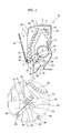
- FIG. 2 is a sectional view illustrating the interior of an air conditioner according to an embodiment of the present invention.
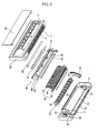
- FIG. 3 is an exploded perspective view of the air conditioner according to the embodiment of the present invention.
- the air conditioner comprises: a body 10 formed with a pair of air suction openings 2 and 4, and an air discharge opening 6; a blowing fan 40 to suck indoor air through the air suction openings 2 and 4 and to discharge the sucked air through the air discharge opening 6; a stabilizer 50 to divide a suction path P1 and an exhaust path P2 of the blowing fan 40; a stabilizer drive unit 60 to move the stabilizer 50 for adjusting a distance d between the blowing fan 40 and the stabilizer 50; and a heat exchanger 46 mounted between the air suction holes 2 and 4 and the blowing fan 40.
- the body 10 includes: a chassis 12; a front panel 20 located at a front end of the chassis 12, the air suction openings 2 and 4 being formed at the front panel 20; and a discharger 30 configured to slidably guide the stabilizer 50, the air discharge opening 6 being formed between the chassis 12 and the discharger 30.
- the body 10 also includes an air guide 14 to define the paths P1 and P2 of the blowing fan 40.
- the air guide 14 also constitutes a housing of the blowing fan 40, and has a rounded shape.
- the chassis 12 is formed with a drain portion 15, which protrudes inward from the chassis 12 to drain condensate water falling from the heat exchanger 46.
- the chassis 12 is provided with a pair of partitions 16 and 17 at opposite lateral sides of the air guide 14.
- the partitions 16 and 17 serve to prevent air that being blown by the blowing fan 40 from leaking in opposite lateral directions.
- a bearing housing 18 is coupled to one of the partitions 16 and 17 of the chassis 12.
- the bearing housing 18 serves to enclose a bearing 41, which supports the blowing fan 40.
- a motor mount 19 is provided at a side of one of the partitions 16 and 17 of the chassis 12, such that a blowing motor 42 for rotating the blowing fan 40 is mounted thereto.
- the front panel 20 is formed at a front surface thereof with the air suction opening 2, and at an upper surface thereof with the air suction opening 4 and a suction grill 5.
- a suction panel 22 is mounted to the front surface of the front panel 20 to be pivotally rotated forward, in order to open or close the front air suction opening 2.
- the discharger 30 includes: a discharge panel 34 internally defining a drain portion 31 to receive and drain condensate water falling from the heat exchanger, the air discharge opening 6 being formed between the discharge panel 34 and the air guide 14 of the chassis 12; a louver 35 to change the horizontal flow direction of air to be discharged through the air discharge opening 6; and a vane 36 to change the vertical flow direction of the discharge air.
- the blowing fan 40 is an elongated cross-flow fan extending horizontally between the partitions 16 and 17.
- the blowing fan 40 has blades configured to forcibly blow air from upside to downside.
- the blowing fan 40 has a left rotating shaft 44 protruding from a left end thereof, and a right rotating shaft 45 protruding from a right end thereof.
- One of the left and right rotating shafts 44 and 45 is connected to a rotating shaft 43 of the blowing motor 42, and the other one is inserted into the bearing 41 to be rotatably supported by the bearing 41.
- the heat exchanger 46 is shaped to have at least one bent portion, such that the heat exchanger 46 with a maximum surface area can be received in the body 10.
- the heat exchanger 46 includes: a first heat exchange portion 47 vertically extending behind a lower portion of the front air suction opening 2; a second heat exchange portion 48 obliquely extending upward and rearward from an upper end of the first heat exchange portion 47; and a third heat exchange portion 49 obliquely extending downward and rearward from an upper end of the second heat exchange portion 48.
- the heat exchanger 46 is generally formed to have two bent portions.
- the stabilizer 50 is slidably disposed at a side of the discharger 30.
- the stabilizer 50 is slidably guided along the discharger 30, more particularly, a rear wall 32 of the drain portion 32 defined in the discharge panel 34. At least one of the discharger 30 and the stabilizer 50 is formed with a sliding guide.
- the sliding guide includes: a protrusion 51 protruding from the stabilizer 50 to the discharger 30; and a sliding groove 33 formed at the discharger 30, more particularly, at the rear wall 32 of the drain portion 31 formed in the discharge panel 34, such that the protrusion 51 is slidably disposed in the sliding groove 33.
- the stabilizer 50 is configured such that a distance d between the stabilizer 50 and the blowing fan 40 is adjustable within a range less than 10 percent of a diameter D of the blowing fan 40.
- the stabilizer drive unit 60 includes: a motor 62; and a power transmission member 64 to reciprocate the stabilizer 50 in accordance with the driving of the motor 62.
- the power transmission member 64 includes a wire 66 connected to the stabilizer 50 while being wound on a rotating shaft 63 of the motor 62.
- the power transmission member 64 also includes a spring 68 to elastically support the stabilizer 50 in an unwinding direction of the wire 66.
- At least two stabilizer drive units 60 are provided to ensure the stable reciprocating movements of the stabilizer 50.
- the stabilizer drive unit 60 may be mounted to a lateral side or upper side of the discharge panel 34, or may be received in the discharge panel 34.
- FIG. 4 is a control block diagram of the air conditioner according to the first embodiment of the present invention.
- the air conditioner according to the present embodiment further comprises: an input unit 72 to input various operational conditions, for example, whether a cooling or heating operation is performed, a desired temperature, and different blowing modes including a weak flow, strong flow, super strong flow modes; and a control unit 74 to control the blowing motor 42 and the motor 62 in accordance with the input data of the input unit 72.
- an input unit 72 to input various operational conditions, for example, whether a cooling or heating operation is performed, a desired temperature, and different blowing modes including a weak flow, strong flow, super strong flow modes
- a control unit 74 to control the blowing motor 42 and the motor 62 in accordance with the input data of the input unit 72.
- the input unit 72 may be a control panel mounted at the air conditioner, or a remote controller.
- control unit 74 controls the motor 62, such that the distance d between the stabilizer 50 and the blowing fan 40 is adjusted in accordance with the set blowing mode.
- FIG. 5 is a graph illustrating the generation of noise in accordance with the distance between the stabilizer and the blowing fan and different blowing modes.
- the control unit 74 controls the motor 62 to move the stabilizer 50, such that the distance between the stabilizer 50 and the blowing fan 40 becomes a minimum noise distance d1 (for example, 15mm) for achieving minimum noise generation. If the blowing mode of the blowing fan 40 is a strong flow mode, the control unit 74 controls the motor 62 to move the stabilizer 50, such that the distance between the stabilizer 50 and the blowing fan 40 becomes a minimum noise distance d2 (for example, 10mm) for achieving minimum noise generation.
- d1 for example, 15mm
- the control unit 74 controls the motor 62 to move the stabilizer 50, such that the distance between the stabilizer 50 and the blowing fan 40 becomes a minimum noise distance d2 (for example, 10mm) for achieving minimum noise generation.
- the control unit 7 controls the motor 62 to move the stabilizer 50, such that the distance between the stabilizer 50 and the blowing fan 40 becomes a minimum noise distance d3 (for example, 5mm) for achieving minimum noise generation.
- the above minimum noise distances d1, d2, and d3 are determined based on a plurality of experiments, and are stored in the control unit 74.
- FIG. 6 is a flow chart illustrating a noise control method of the air conditioner according to the present invention.
- control unit 74 confirms the blowing mode of the air conditioner.
- the control unit 74 drives the blowing motor 42 in a low speed mode, such that the blowing fan is rotated at a low speed (S1 and S2).
- control unit 74 controls the motor 62 in the weak flow mode, such that the stabilizer 50 is spaced apart from the blowing fan 40 by the minimum noise distance d1 (S2).
- the rotating shaft 63 When the motor 62 is rotated in the weak flow mode, the rotating shaft 63 is rotated by an angle corresponding to the minimum noise distance d1. In this case, the wire 66 is wound on the rotating shaft 63 with at least one turn, thereby tensioning the stabilizer 50.
- the stabilizer 50 is moved in an opposite direction of the blowing fan 40 in accordance with the tensioning effect of the wire 66, such that the distance d between the stabilizer 50 and the blowing fan 40 is adjusted to the minimum noise distance d1.
- the minimum noise distance d1 between the stabilizer 50 and the blowing fan 40 is held.
- the stabilizer 50 has a fixed position in accordance with the tensioning effect of the wire 66 while compressing the spring 68.
- the blowing fan 40 is rotated at a low speed in a state wherein the position of the stabilizer 50 is fixed, indoor air is sucked into the body 10 through the front and upper air suction openings 2 and 4.
- the sucked air is heated or cooled as it is heat exchanged with a refrigerant while passing through the heat exchanger 46. After that, the heat exchanged air is sucked into the blowing fan 40 through the suction path P1 defined between the stabilizer 50 and the upper portion of the air guide 14.
- the control unit 74 drives the blowing motor 42 in a high speed/super high speed mode, such that the blowing fan is rotated at a high speed/super high speed (S3 and S4, or S5 and S6).
- control unit 74 controls the motor 62 in the strong/super strong mode, such the stabilizer 50 is spaced apart from the blowing fan 40 by the minimum noise distance d2 or d3 (S4 or S6).
- the rotating shaft 63 When the motor 62 is rotated in the strong/super strong flow mode, the rotating shaft 63 is rotated by an angle corresponding to the minimum noise distance d2 or d3. In this case, the wire 66 is wound on the rotating shaft 63 with at least one turn, thereby tensioning the stabilizer 50, similar to the weak flow mode.
- the stabilizer 50 is moved in an opposite direction of the blowing fan 40 in accordance with the tensioning effect of the wire 66, such that the distance d between the stabilizer 50 and the blowing fan 40 is adjusted to the minimum noise distance d2 or d3.
- the minimum noise distance d2 or d3 between the stabilizer 50 and the blowing fan 40 is held.
- the stabilizer 50 has a fixed position in accordance with the tensioning effect of the wire 66 while compressing the spring 68.
- the high speed/super high speed rotation of the blowing fan 40 and the resulting air flow are identical to those of the weak flow mode, and thus, a detailed description thereof will be omitted.
- the control unit 74 controls the motor 62 in accordance with one mode selected from among the weak flow, strong flow, super strong flow modes, and subsequently, controls the motor 62 in accordance with another mode except for the selected mode, the wire 66 is further wound or unwound to adjust the minimum noise distance d1, d2, or d3. If the mode is changed such that the distance d between the blowing fan 40 and the stabilizer 50 is reduced, the spring 68 applies an elastic force to the stabilizer 50, thereby assisting the rapid displacement and holding of the stabilizer 50.
- FIG. 7 is a sectional view of an air conditioner according to another embodiment of the present invention, a circle illustrating the important part of the air conditioner in enlarged scale.
- a power transmission member 64' includes: a rack 66' formed at the stabilizer 50; and a pinion 68' mounted to the rotating shaft 63 of the motor 62 to be engaged with the rack 66'.
- Other configurations and operations except for the power transmission member 64' are identical to the previously described embodiment of the present invention. Thus, the same reference numerals will be used in the following description, and a detailed description thereof will be omitted.
- the motor 62 is operated in accordance with the weak, strong, and super strong flow modes. If the motor 62 is operated in one of the weak, strong, and super strong flow modes, the rack 66' is advanced or retracted by the pinion 68', such that the stabilizer 50 is spaced apart from the blowing fan by the minimum noise distance d1, d2, or d3, in the same manner as the previously described embodiment of the present invention.
- the stabilizer drive unit may include a permanent magnet or electromagnet to move or fix the stabilizer using a magnetic force.
- an air conditioner according to the present invention having the above described configuration provides the following several effects.
- a stabilizer can be moved in accordance with the operation of a stabilizer drive unit, such that a distance between the stabilizer and a blowing fan can be adjusted. This has the effect of minimizing noise generated due to the stabilizer.
- the movement of the stabilizer is guided in a sliding manner by use of a discharger, whereby the stabilizer is easily displaceable.
- the discharger also has the effect of preventing the stabilizer from unintentionally moving from a fixed position thereof.
- the distance between the stabilizer and the blowing fan can be adjusted within a range less than 10 percent of a diameter of the blowing fan. This has the effect of preventing the deterioration of blowing efficiency, which has been conventionally generated when the distance between the stabilizer and the blowing fan is excessively large. As a result, the stabilizer can minimize the generation of noise.
- a stabilizer drive unit includes: a motor; a wire connected to the stabilizer while being wound on a rotating shaft of the motor; and a spring to elastically support the stabilizer in an unwinding direction of the wire.
- the stabilizer drive unit when the stabilizer drive unit includes: a rack provided at the stabilizer; and a pinion mounted to the rotating shaft of the motor to be engaged with the rack, the stabilizer drive unit can achieve a more simplified configuration with low manufacturing costs.
- the distance between the stabilizer and the blowing fan can be appropriately adjusted in accordance with different blowing modes.
- the generation of noise can be restricted to the minimum level throughout the entire blowing region of the air conditioner, resulting in an improvement in noise attenuation effect.
Landscapes
- Engineering & Computer Science (AREA)
- Mechanical Engineering (AREA)
- General Engineering & Computer Science (AREA)
- Chemical & Material Sciences (AREA)
- Combustion & Propulsion (AREA)
- Physics & Mathematics (AREA)
- Thermal Sciences (AREA)
- Air-Conditioning Room Units, And Self-Contained Units In General (AREA)
- Air Conditioning Control Device (AREA)
Abstract
Description
- The present invention relates to an air conditioner and a noise control method thereof, and more particularly, to an air conditioner wherein a distance between a blowing fan and a stabilizer, which divides a suction path and an exhaust path of the blowing fan, is adjustable, and a noise control method thereof.
- Generally, an air conditioner is an apparatus for cooling or heating a room, in order to create a more pleasant room environment. To cool and heat a room, the air conditioner employs a refrigerant cycle including a compressor, a 4-way valve, an outdoor heat exchanger (condenser or evaporator), an expander, and an indoor heat exchanger (evaporator or condenser). The air conditioner is basically classified into a discrete type and an integral type.
- Although both the discrete type and integral type air conditioners have the same function as each other, they are different in structure from each other. Specifically, in the case of the discrete type air conditioner wherein an indoor unit is separated from an outdoor unit, the indoor unit is provided with a cooling/radiating device, an indoor fan, and an indoor fan motor, while the outdoor unit is provided with a radiating/cooling device, a compression device, an outdoor fan, and an outdoor fan motor, both the indoor and outdoor units being connected to each other by use of refrigerant pipes. The integral type air conditioner is configured such that cooling and radiation functions are performed by one integral unit. The integral type air conditioner is mounted to a window frame or opening drilled through a wall.
- FIG. 1 is a sectional view illustrating the interior of a conventional air conditioner.
- As shown in FIG. 1, the conventional air conditioner comprises: a
chassis 102; afront grill 110 coupled to a front end of thechassis 102 and formed with anair suction opening 104 and asuction grill 106; asuction grill 112 rotatably connected to a front surface of thefront grill 110; a blowingfan 116 disposed between thechassis 102 and thefront grill 110; and aheat exchanger 118 disposed between the blowingfan 116,air suction opening 104, andsuction grill 106. - The
air suction opening 104 is formed at the front surface of thefront grill 110, and thesuction grill 106 is integrally formed at an upper surface of thefront grill 110. - The
front grill 110 is provided at the front surface thereof with a pre-filter 105. The pre-filter 105 is used to filter impurities contained in air that is being sucked through the front air suction opening 104. - The
suction grill 112, which is provided at the front surface of thefront grill 110, has a function of protecting both the front air suction opening 104 and the pre-filter 105. Thesuction grill 112 has an upper end connected to an upper location of thefront grill 110 in a pivotally rotatable manner. - A
condensate water tray 119 is formed at a lower location of thefront grill 110 to receive condensate water falling from theindoor heat exchanger 118. The conventional air conditioner further comprises adischarge grill 124 mounted between thecondensate water tray 119 and thechassis 102. Thedischarge grill 124 is formed with an air discharge opening 120. - The
discharge grill 124 includes: alouver 121 to change the horizontal flow direction of air to be discharged through the air discharge opening 120, and avane 122 to change the vertical flow direction of the discharge air. - The
discharge grill 124 further includes astabilizer 126 to divide a suction path and an exhaust path of the blowingfan 116. - The
stabilizer 126 is integrally formed with thedischarge grill 124 such that it is spaced apart from the blowingfan 116 by a predetermined distance d. - With the conventional air conditioner having the above described configuration, if the blowing
fan 116 rotates, indoor air in front of thesuction grill 112 is sucked into a space defined between thefront grill 110 and thechassis 102 by passing through thesuction grill 112 and the front air suction opening 104, while impurities contained in the indoor air are filtered by the pre-filter 105. - Simultaneously, indoor air above the
front grill 110 is also sucked into the space between thefront grill 110 and thechassis 102 by passing through theupper suction grill 106 formed at the upper surface of thefront grill 110. - The sucked indoor air passes through the
indoor heat exchanger 118, thereby being cooled or heated by a refrigerant that circulates through theindoor heat exchanger 118. After that, the cooled or heated air is introduced into the blowingfan 116. Thereby, in accordance with the blowing operation of thefan 116, the cooled or heated air is discharged into a room through the air discharge opening 120 while being guided by thelouver 121 and thevane 122. - A problem of the conventional air conditioner is that the
stabilizer 126 has a large effect on the total noise produced by the air conditioner. Specifically, thestabilizer 126 has a fixed shape and installation position regardless of conditions (for example, flow rate, etc.) of the blowingfan 116, and therefore, seriously limits the minimization of noise generated. - It is an object of the present invention to provide an air conditioner wherein a distance between a stabilizer and a blowing fan is adjustable, whereby the generation of noise can be minimized.
- It is another object of the present invention to provide a noise control method of an air conditioner wherein a distance between a stabilizer and a blowing fan is adjustable in accordance with different blowing modes, whereby the generation of noise can be minimized throughout the entire blowing region of the air conditioner.
- In accordance with an aspect of the present invention, the above and other objects can be accomplished by the provision of an air conditioner comprising: a body formed with a pair of air suction openings, and an air discharge opening; a blowing fan to suck air through the air suction openings and to discharge the sucked air through the air discharge opening; a stabilizer to divide a suction path and an exhaust path of the blowing fan; and a stabilizer drive unit to move the stabilizer for adjusting a distance between the blowing fan and the stabilizer.
- Preferably, the body may include: a chassis; a front panel located at a front end of the chassis, the air suction openings being formed at the front panel; and a discharger configured to slidably guide the stabilizer, the air discharge opening being formed between the chassis and the discharger.
- Preferably, the air conditioner may further comprise: a pair of sliding guides to guide sliding movement of the stabilizer.
- Preferably, the sliding guides may include: a protrusion protruding from the stabilizer toward the discharger; and a sliding groove formed at the discharger, such that the protrusion is slidably disposed in the sliding groove.
- Preferably, the stabilizer drive unit may include: a motor; and a power transmission member to reciprocate the stabilizer in accordance with the driving of the motor.
- Preferably, the air conditioner may further comprise: a control unit to control the motor, such that the distance between the stabilizer and the blowing fan is adjusted in accordance with a blowing mode.
- Preferably, the power transmission member may include: a wire connected to the stabilizer while being wound on a rotating shaft of the motor; and a spring to elastically support the stabilizer in an unwinding direction of the wire.
- Preferably, the power transmission member may include: a rack formed at the stabilizer; and a pinion mounted to the rotating shaft of the motor to be engaged with the rack.
- Preferably, the air conditioner may further comprise: a heat exchanger mounted between the air suction holes and the blowing fan.
- In accordance with another aspect of the present invention, the above and other objects can be accomplished by the provision of a noise control method of an air conditioner comprising the steps of: confirming a blowing mode of the air conditioner; and adjusting a distance between a stabilizer and a blowing fan in accordance with the confirmed blowing mode.
- The air conditioner of the present invention has the effect of minimizing noise generated due to the stabilizer since the stabilizer can be moved in accordance with the operation of the stabilizer drive unit, such that a distance between the stabilizer and the blowing fan can be adjusted.
- In this case, the movement of the stabilizer is guided in a sliding manner by use of a discharger, whereby the stabilizer is easily displaceable. This also has the effect of preventing the stabilizer from unintentionally moving from a fixed position thereof.
- The distance between the stabilizer and the blowing fan can be adjusted within a range less than 10 percent of a diameter of the blowing fan. This effectively prevents the deterioration of blowing efficiency, which has been conventionally generated when the distance between the stabilizer and the blowing fan is excessively large. As a result, the stabilizer can minimize the generation of noise.
- The stabilizer drive unit according to the present invention includes: a motor; a wire connected to the stabilizer while being wound on a rotating shaft of the motor; and a spring to elastically support the stabilizer in an unwinding direction of the wire. Through the use of the stabilizer drive unit, the stabilizer can be rapidly moved.
- Alternatively, the stabilizer drive unit may include: a rack provided at the stabilizer; and a pinion mounted to the rotating shaft of the motor to be engaged with the rack. In this case, the stabilizer drive unit can achieve a more simplified configuration with low manufacturing costs.
- With a noise control method of the air conditioner according to the present invention, the distance between the stabilizer and the blowing fan can be appropriately adjusted in accordance with different blowing modes. As a result, the generation of noise can be restricted to the minimum level throughout the entire blowing region of the air conditioner, resulting in an improvement in noise attenuation effect.
- The above and other objects, features and other advantages of the present invention will be more clearly understood from the following detailed description taken in conjunction with the accompanying drawings, in which:
- FIG. 1 is a sectional view illustrating the interior of a conventional air conditioner;
- FIG. 2 is a sectional view illustrating the interior of an air conditioner according to an embodiment of the present invention;
- FIG. 3 is an exploded perspective view of the air conditioner according to the embodiment of the present invention;
- FIG. 4 is a control block diagram of the air conditioner according to the embodiment of the present invention;
- FIG. 5 is a graph illustrating the generation of noise in accordance with a distance between a stabilizer and a blowing fan and different blowing modes;
- FIG. 6 is a flow chart illustrating a noise control method of the air conditioner according to the present invention; and
- FIG. 7 is a sectional view of an air conditioner according to another embodiment of the present invention, a circle illustrating the important part of the air conditioner in enlarged scale.
- Now, preferred embodiments of the present invention will be explained with reference to the accompanying drawings.
- FIG. 2 is a sectional view illustrating the interior of an air conditioner according to an embodiment of the present invention. FIG. 3 is an exploded perspective view of the air conditioner according to the embodiment of the present invention.
- As shown in FIGS. 2 and 3, the air conditioner according to the embodiment of the present invention comprises: a
body 10 formed with a pair ofair suction openings air discharge opening 6; a blowingfan 40 to suck indoor air through theair suction openings air discharge opening 6; astabilizer 50 to divide a suction path P1 and an exhaust path P2 of the blowingfan 40; a stabilizer drive unit 60 to move thestabilizer 50 for adjusting a distance d between the blowingfan 40 and thestabilizer 50; and aheat exchanger 46 mounted between theair suction holes fan 40. - The
body 10 includes: achassis 12; afront panel 20 located at a front end of thechassis 12, theair suction openings front panel 20; and adischarger 30 configured to slidably guide thestabilizer 50, theair discharge opening 6 being formed between thechassis 12 and thedischarger 30. - The
body 10 also includes anair guide 14 to define the paths P1 and P2 of the blowingfan 40. - The
air guide 14 also constitutes a housing of the blowingfan 40, and has a rounded shape. - The
chassis 12 is formed with adrain portion 15, which protrudes inward from thechassis 12 to drain condensate water falling from theheat exchanger 46. - Referring to FIG. 3, the
chassis 12 is provided with a pair ofpartitions air guide 14. Thepartitions fan 40 from leaking in opposite lateral directions. - A bearing
housing 18 is coupled to one of thepartitions chassis 12. The bearinghousing 18 serves to enclose abearing 41, which supports the blowingfan 40. - A
motor mount 19 is provided at a side of one of thepartitions chassis 12, such that a blowingmotor 42 for rotating the blowingfan 40 is mounted thereto. - The
front panel 20 is formed at a front surface thereof with theair suction opening 2, and at an upper surface thereof with theair suction opening 4 and asuction grill 5. - A
suction panel 22 is mounted to the front surface of thefront panel 20 to be pivotally rotated forward, in order to open or close the frontair suction opening 2. - The
discharger 30 includes: adischarge panel 34 internally defining adrain portion 31 to receive and drain condensate water falling from the heat exchanger, theair discharge opening 6 being formed between thedischarge panel 34 and theair guide 14 of thechassis 12; alouver 35 to change the horizontal flow direction of air to be discharged through theair discharge opening 6; and avane 36 to change the vertical flow direction of the discharge air. - As shown in FIG. 3, the blowing
fan 40 is an elongated cross-flow fan extending horizontally between thepartitions fan 40 has blades configured to forcibly blow air from upside to downside. - The blowing
fan 40 has a left rotatingshaft 44 protruding from a left end thereof, and a rightrotating shaft 45 protruding from a right end thereof. - One of the left and right
rotating shafts rotating shaft 43 of the blowingmotor 42, and the other one is inserted into the bearing 41 to be rotatably supported by thebearing 41. - The
heat exchanger 46 is shaped to have at least one bent portion, such that theheat exchanger 46 with a maximum surface area can be received in thebody 10. In the present embodiment, specifically, theheat exchanger 46 includes: a firstheat exchange portion 47 vertically extending behind a lower portion of the frontair suction opening 2; a secondheat exchange portion 48 obliquely extending upward and rearward from an upper end of the firstheat exchange portion 47; and a thirdheat exchange portion 49 obliquely extending downward and rearward from an upper end of the secondheat exchange portion 48. With this configuration, theheat exchanger 46 is generally formed to have two bent portions. - The
stabilizer 50 is slidably disposed at a side of thedischarger 30. - Specifically, the
stabilizer 50 is slidably guided along thedischarger 30, more particularly, arear wall 32 of thedrain portion 32 defined in thedischarge panel 34. At least one of thedischarger 30 and thestabilizer 50 is formed with a sliding guide. - As shown in FIG. 2, the sliding guide includes: a
protrusion 51 protruding from thestabilizer 50 to thedischarger 30; and a slidinggroove 33 formed at thedischarger 30, more particularly, at therear wall 32 of thedrain portion 31 formed in thedischarge panel 34, such that theprotrusion 51 is slidably disposed in the slidinggroove 33. - The
stabilizer 50 is configured such that a distance d between thestabilizer 50 and the blowingfan 40 is adjustable within a range less than 10 percent of a diameter D of the blowingfan 40. - Referring to FIG. 2, the stabilizer drive unit 60 includes: a
motor 62; and apower transmission member 64 to reciprocate thestabilizer 50 in accordance with the driving of themotor 62. - The
power transmission member 64 includes awire 66 connected to thestabilizer 50 while being wound on arotating shaft 63 of themotor 62. - The
power transmission member 64 also includes aspring 68 to elastically support thestabilizer 50 in an unwinding direction of thewire 66. - Here, it is preferable that at least two stabilizer drive units 60 are provided to ensure the stable reciprocating movements of the
stabilizer 50. - The stabilizer drive unit 60 may be mounted to a lateral side or upper side of the
discharge panel 34, or may be received in thedischarge panel 34. - FIG. 4 is a control block diagram of the air conditioner according to the first embodiment of the present invention.
- The air conditioner according to the present embodiment further comprises: an
input unit 72 to input various operational conditions, for example, whether a cooling or heating operation is performed, a desired temperature, and different blowing modes including a weak flow, strong flow, super strong flow modes; and acontrol unit 74 to control the blowingmotor 42 and themotor 62 in accordance with the input data of theinput unit 72. - The
input unit 72 may be a control panel mounted at the air conditioner, or a remote controller. - If a specific blowing mode is manually set by use of the
input unit 72, or is automatically set in accordance with a desired temperature or defrosting operation, etc., thecontrol unit 74 controls themotor 62, such that the distance d between thestabilizer 50 and the blowingfan 40 is adjusted in accordance with the set blowing mode. - FIG. 5 is a graph illustrating the generation of noise in accordance with the distance between the stabilizer and the blowing fan and different blowing modes.
- Referring to FIG. 5, preferably, if the blowing mode of the blowing
fan 40 is a weak flow mode, thecontrol unit 74 controls themotor 62 to move thestabilizer 50, such that the distance between thestabilizer 50 and the blowingfan 40 becomes a minimum noise distance d1 (for example, 15mm) for achieving minimum noise generation. If the blowing mode of the blowingfan 40 is a strong flow mode, thecontrol unit 74 controls themotor 62 to move thestabilizer 50, such that the distance between thestabilizer 50 and the blowingfan 40 becomes a minimum noise distance d2 (for example, 10mm) for achieving minimum noise generation. Also, if the blowing mode of the blowingfan 40 is a super strong flow mode, the control unit 7 controls themotor 62 to move thestabilizer 50, such that the distance between thestabilizer 50 and the blowingfan 40 becomes a minimum noise distance d3 (for example, 5mm) for achieving minimum noise generation. - Preferably, the above minimum noise distances d1, d2, and d3 are determined based on a plurality of experiments, and are stored in the
control unit 74. - Hereinafter, the operation of the air conditioner having the above described configuration will be explained.
- FIG. 6 is a flow chart illustrating a noise control method of the air conditioner according to the present invention.
- First, the
control unit 74 confirms the blowing mode of the air conditioner. - If the weak flow mode is manually set or is automatically set in accordance with a desired temperature or defrosting operation, etc., the
control unit 74 drives the blowingmotor 42 in a low speed mode, such that the blowing fan is rotated at a low speed (S1 and S2). - In addition to controlling the blowing
motor 42, simultaneously, thecontrol unit 74 controls themotor 62 in the weak flow mode, such that thestabilizer 50 is spaced apart from the blowingfan 40 by the minimum noise distance d1 (S2). - When the
motor 62 is rotated in the weak flow mode, the rotatingshaft 63 is rotated by an angle corresponding to the minimum noise distance d1. In this case, thewire 66 is wound on therotating shaft 63 with at least one turn, thereby tensioning thestabilizer 50. - Thereby, the
stabilizer 50 is moved in an opposite direction of the blowingfan 40 in accordance with the tensioning effect of thewire 66, such that the distance d between thestabilizer 50 and the blowingfan 40 is adjusted to the minimum noise distance d1. - After the
motor 62 stops, the minimum noise distance d1 between thestabilizer 50 and the blowingfan 40 is held. - In this case, the
stabilizer 50 has a fixed position in accordance with the tensioning effect of thewire 66 while compressing thespring 68. - Meanwhile, if the blowing
fan 40 is rotated at a low speed in a state wherein the position of thestabilizer 50 is fixed, indoor air is sucked into thebody 10 through the front and upperair suction openings heat exchanger 46. After that, the heat exchanged air is sucked into the blowingfan 40 through the suction path P1 defined between thestabilizer 50 and the upper portion of theair guide 14. - The air, sucked into the blowing
fan 40, is forcibly blown by the blowingfan 40, to pass through the exhaust path P2 defined between thedischarge panel 34 and the lower portion of theair guide 14. Thereby, the air is again discharged into a room by passing through theair discharge opening 6. - Conversely, if the strong/super strong flow mode is manually set or is automatically set in accordance with a desired temperature or defrosting operation, etc., the
control unit 74 drives the blowingmotor 42 in a high speed/super high speed mode, such that the blowing fan is rotated at a high speed/super high speed (S3 and S4, or S5 and S6). - In addition to controlling the blowing
motor 42, simultaneously, thecontrol unit 74 controls themotor 62 in the strong/super strong mode, such thestabilizer 50 is spaced apart from the blowingfan 40 by the minimum noise distance d2 or d3 (S4 or S6). - When the
motor 62 is rotated in the strong/super strong flow mode, the rotatingshaft 63 is rotated by an angle corresponding to the minimum noise distance d2 or d3. In this case, thewire 66 is wound on therotating shaft 63 with at least one turn, thereby tensioning thestabilizer 50, similar to the weak flow mode. - Thereby, the
stabilizer 50 is moved in an opposite direction of the blowingfan 40 in accordance with the tensioning effect of thewire 66, such that the distance d between thestabilizer 50 and the blowingfan 40 is adjusted to the minimum noise distance d2 or d3. After themotor 62 stops, the minimum noise distance d2 or d3 between thestabilizer 50 and the blowingfan 40 is held. - Similar to the weak flow mode, the
stabilizer 50 has a fixed position in accordance with the tensioning effect of thewire 66 while compressing thespring 68. - Hereinafter, the high speed/super high speed rotation of the blowing
fan 40 and the resulting air flow are identical to those of the weak flow mode, and thus, a detailed description thereof will be omitted. - Meanwhile, if the
control unit 74 controls themotor 62 in accordance with one mode selected from among the weak flow, strong flow, super strong flow modes, and subsequently, controls themotor 62 in accordance with another mode except for the selected mode, thewire 66 is further wound or unwound to adjust the minimum noise distance d1, d2, or d3. If the mode is changed such that the distance d between the blowingfan 40 and thestabilizer 50 is reduced, thespring 68 applies an elastic force to thestabilizer 50, thereby assisting the rapid displacement and holding of thestabilizer 50. - FIG. 7 is a sectional view of an air conditioner according to another embodiment of the present invention, a circle illustrating the important part of the air conditioner in enlarged scale.
- In the air conditioner according to the present embodiment, a power transmission member 64' includes: a rack 66' formed at the
stabilizer 50; and a pinion 68' mounted to therotating shaft 63 of themotor 62 to be engaged with the rack 66'. Other configurations and operations except for the power transmission member 64' are identical to the previously described embodiment of the present invention. Thus, the same reference numerals will be used in the following description, and a detailed description thereof will be omitted. - Similar to the previously described embodiment of the present invention, the
motor 62 is operated in accordance with the weak, strong, and super strong flow modes. If themotor 62 is operated in one of the weak, strong, and super strong flow modes, the rack 66' is advanced or retracted by the pinion 68', such that thestabilizer 50 is spaced apart from the blowing fan by the minimum noise distance d1, d2, or d3, in the same manner as the previously described embodiment of the present invention. - It should be understood that the present invention is not limited to the above described embodiments, and various modifications thereof are possible without departing from the scope and spirit of the invention. For example, the stabilizer drive unit may include a permanent magnet or electromagnet to move or fix the stabilizer using a magnetic force.
- As is apparent from the above description, an air conditioner according to the present invention having the above described configuration provides the following several effects.
- Firstly, a stabilizer can be moved in accordance with the operation of a stabilizer drive unit, such that a distance between the stabilizer and a blowing fan can be adjusted. This has the effect of minimizing noise generated due to the stabilizer.
- Secondly, the movement of the stabilizer is guided in a sliding manner by use of a discharger, whereby the stabilizer is easily displaceable. The discharger also has the effect of preventing the stabilizer from unintentionally moving from a fixed position thereof.
- Thirdly, the distance between the stabilizer and the blowing fan can be adjusted within a range less than 10 percent of a diameter of the blowing fan. This has the effect of preventing the deterioration of blowing efficiency, which has been conventionally generated when the distance between the stabilizer and the blowing fan is excessively large. As a result, the stabilizer can minimize the generation of noise.
- Fourthly, according to an embodiment of the present invention, a stabilizer drive unit includes: a motor; a wire connected to the stabilizer while being wound on a rotating shaft of the motor; and a spring to elastically support the stabilizer in an unwinding direction of the wire. Through the use of the stabilizer drive unit, the stabilizer can be rapidly moved.
- Fifthly, when the stabilizer drive unit includes: a rack provided at the stabilizer; and a pinion mounted to the rotating shaft of the motor to be engaged with the rack, the stabilizer drive unit can achieve a more simplified configuration with low manufacturing costs.
- Sixthly, with a noise control method of the air conditioner according to the present invention, the distance between the stabilizer and the blowing fan can be appropriately adjusted in accordance with different blowing modes. As a result, the generation of noise can be restricted to the minimum level throughout the entire blowing region of the air conditioner, resulting in an improvement in noise attenuation effect.
Claims (10)
- An air conditioner comprising:a body (10) formed with a pair of air suction openings (2 and 4), and an air discharge opening (6);a blowing fan (40) to suck air through the air suction openings (2 and 4) and to discharge the sucked air through the air discharge opening (6);a stabilizer (50) to divide a suction path (P1) and an exhaust path (P2) of the blowing fan (40); anda stabilizer drive unit (60) to move the stabilizer (50) for adjusting a distance between the blowing fan (40) and the stabilizer (50).
- The air conditioner as set forth in claim 1, wherein the body (10) includes:a chassis (12);a front panel (20) located at a front end of the chassis (12), the air suction openings (2 and 4) being formed at the front panel (20); anda discharger (30) configured to slidably guide the stabilizer (50), the air discharge opening (6) being formed between the chassis (12) and the discharger (30).
- The air conditioner as set forth in claim 2, further comprising:a pair of sliding guides (33 and 51) to guide sliding movement of the stabilizer (50).
- The air conditioner as set forth in claim 3, wherein the sliding guides include:a protrusion (51) protruding from the stabilizer (50) toward the discharger (30); anda sliding groove (33) formed at the discharger (30), such that the protrusion (51) is slidably disposed in the sliding groove (33).
- The air conditioner as set forth in any of claims 1 to 4, wherein the stabilizer drive unit (60) includes:a motor (62); anda power transmission member (64) to reciprocate the stabilizer (50) in accordance with the driving of the motor (62).
- The air conditioner as set forth in claim 5, further comprising:a control unit (74) to control the motor (62), such that the distance between the stabilizer (50) and the blowing fan (40) is adjusted in accordance with a blowing mode.
- The air conditioner as set forth in claim 5, wherein the power transmission member (64) includes:a wire (66) connected to the stabilizer (50) while being wound on a rotating shaft (63) of the motor (62); anda spring (68) to elastically support the stabilizer (50) in an unwinding direction of the wire (66).
- The air conditioner as set forth in claim 5, wherein the power transmission member (64) includes:a rack (66') formed at the stabilizer (50); anda pinion (68') mounted to the rotating shaft (63) of the motor (62) to be engaged with the rack (66').
- The air conditioner as set forth in any one of claims 1 to 8, further comprising:a heat exchanger (46) mounted between the air suction holes (2 and 4) and the blowing fan (40).
- A noise control method of an air conditioner comprising the steps of:confirming a blowing mode of the air conditioner (S1, S3, or S5); andadjusting a distance between a stabilizer and a blowing fan in accordance with the confirmed blowing mode (S2, S4, or S6).
Applications Claiming Priority (1)
| Application Number | Priority Date | Filing Date | Title |
|---|---|---|---|
| KR1020050063800A KR100722276B1 (en) | 2005-07-14 | 2005-07-14 | Air conditioner and its noise control method |
Publications (1)
| Publication Number | Publication Date |
|---|---|
| EP1744106A1 true EP1744106A1 (en) | 2007-01-17 |
Family
ID=37102193
Family Applications (1)
| Application Number | Title | Priority Date | Filing Date |
|---|---|---|---|
| EP06005791A Withdrawn EP1744106A1 (en) | 2005-07-14 | 2006-03-21 | Air conditioner and noise control method thereof |
Country Status (2)
| Country | Link |
|---|---|
| EP (1) | EP1744106A1 (en) |
| KR (1) | KR100722276B1 (en) |
Cited By (7)
| Publication number | Priority date | Publication date | Assignee | Title |
|---|---|---|---|---|
| CN106482230A (en) * | 2015-08-27 | 2017-03-08 | 青岛海尔智能技术研发有限公司 | A kind of mixed flow air-conditioning |
| CN107781904A (en) * | 2016-08-25 | 2018-03-09 | 珠海格力电器股份有限公司 | Air conditioner |
| CN110057071A (en) * | 2019-05-21 | 2019-07-26 | 宁波奥克斯电气股份有限公司 | A kind of air guide structure and air conditioner |
| WO2021088364A1 (en) * | 2019-11-04 | 2021-05-14 | 珠海格力电器股份有限公司 | Indoor unit and air conditioner having same |
| US11149966B2 (en) * | 2017-03-09 | 2021-10-19 | Mitsubishi Electric Corporation | Indoor unit of air-conditioning apparatus |
| JP2022130587A (en) * | 2018-02-06 | 2022-09-06 | シャープ株式会社 | air conditioner |
| CN116989391A (en) * | 2022-04-26 | 2023-11-03 | 宁波奥克斯电气股份有限公司 | Air conditioner noise reduction pipeline and air conditioner |
Families Citing this family (2)
| Publication number | Priority date | Publication date | Assignee | Title |
|---|---|---|---|---|
| KR101285176B1 (en) | 2007-12-11 | 2013-07-23 | 삼성전자주식회사 | Air conditioner |
| KR102149736B1 (en) | 2013-08-09 | 2020-08-31 | 삼성전자주식회사 | Indoor unit of air conditioner |
Citations (6)
| Publication number | Priority date | Publication date | Assignee | Title |
|---|---|---|---|---|
| JPS60219496A (en) * | 1984-04-17 | 1985-11-02 | Komatsu Ltd | Cross flow fan |
| JPH04281122A (en) * | 1991-03-08 | 1992-10-06 | Sharp Corp | Air conditioner |
| JPH0599445A (en) * | 1991-10-11 | 1993-04-20 | Sharp Corp | Air conditioner |
| JPH05215093A (en) * | 1992-02-05 | 1993-08-24 | Mitsubishi Electric Corp | Cross flow type blower |
| JP2000088273A (en) * | 1998-09-16 | 2000-03-31 | Funai Electric Co Ltd | Air conditioner |
| WO2003033965A2 (en) * | 2001-10-15 | 2003-04-24 | Lg Electronics Inc. | Indoor unit of packaged air conditioner |
Family Cites Families (2)
| Publication number | Priority date | Publication date | Assignee | Title |
|---|---|---|---|---|
| KR200231321Y1 (en) * | 1998-11-25 | 2001-10-25 | 전주범 | Stabilizer for air volume control of separate air conditioner |
| KR20040092904A (en) * | 2003-04-29 | 2004-11-04 | 주식회사 대우일렉트로닉스 | Variable stabilizer in air conditioner |
-
2005
- 2005-07-14 KR KR1020050063800A patent/KR100722276B1/en not_active Expired - Fee Related
-
2006
- 2006-03-21 EP EP06005791A patent/EP1744106A1/en not_active Withdrawn
Patent Citations (6)
| Publication number | Priority date | Publication date | Assignee | Title |
|---|---|---|---|---|
| JPS60219496A (en) * | 1984-04-17 | 1985-11-02 | Komatsu Ltd | Cross flow fan |
| JPH04281122A (en) * | 1991-03-08 | 1992-10-06 | Sharp Corp | Air conditioner |
| JPH0599445A (en) * | 1991-10-11 | 1993-04-20 | Sharp Corp | Air conditioner |
| JPH05215093A (en) * | 1992-02-05 | 1993-08-24 | Mitsubishi Electric Corp | Cross flow type blower |
| JP2000088273A (en) * | 1998-09-16 | 2000-03-31 | Funai Electric Co Ltd | Air conditioner |
| WO2003033965A2 (en) * | 2001-10-15 | 2003-04-24 | Lg Electronics Inc. | Indoor unit of packaged air conditioner |
Cited By (7)
| Publication number | Priority date | Publication date | Assignee | Title |
|---|---|---|---|---|
| CN106482230A (en) * | 2015-08-27 | 2017-03-08 | 青岛海尔智能技术研发有限公司 | A kind of mixed flow air-conditioning |
| CN107781904A (en) * | 2016-08-25 | 2018-03-09 | 珠海格力电器股份有限公司 | Air conditioner |
| US11149966B2 (en) * | 2017-03-09 | 2021-10-19 | Mitsubishi Electric Corporation | Indoor unit of air-conditioning apparatus |
| JP2022130587A (en) * | 2018-02-06 | 2022-09-06 | シャープ株式会社 | air conditioner |
| CN110057071A (en) * | 2019-05-21 | 2019-07-26 | 宁波奥克斯电气股份有限公司 | A kind of air guide structure and air conditioner |
| WO2021088364A1 (en) * | 2019-11-04 | 2021-05-14 | 珠海格力电器股份有限公司 | Indoor unit and air conditioner having same |
| CN116989391A (en) * | 2022-04-26 | 2023-11-03 | 宁波奥克斯电气股份有限公司 | Air conditioner noise reduction pipeline and air conditioner |
Also Published As
| Publication number | Publication date |
|---|---|
| KR20070009866A (en) | 2007-01-19 |
| KR100722276B1 (en) | 2007-05-28 |
Similar Documents
| Publication | Publication Date | Title |
|---|---|---|
| CN106352401B (en) | Air conditioner | |
| CN107850322B (en) | air conditioner | |
| CN108139085B (en) | air conditioner | |
| KR20090038555A (en) | Air Conditioner with Discharge Wind Direction Control | |
| KR100581312B1 (en) | Wall Mounted Air Conditioner | |
| CN110573806B (en) | Air conditioner | |
| EP1744106A1 (en) | Air conditioner and noise control method thereof | |
| KR20240020721A (en) | Air Conditional | |
| US6330807B1 (en) | Structure for facilitating assembly of an air conditioning unit having a removable chassis | |
| KR100727461B1 (en) | Indoor unit of air conditioner | |
| KR20090017290A (en) | Indoor unit of air conditioner | |
| KR102086376B1 (en) | Air conditioner | |
| KR20230069898A (en) | Air Conditional | |
| KR20050049948A (en) | Indoor unit of spilt type air-conditioner | |
| CN1179157C (en) | Room air conditioner | |
| KR20180068641A (en) | Indoor unit for air conditioner | |
| JP2019066148A (en) | Floor type air conditioner | |
| KR20010028973A (en) | Wind direction controller for air conditioner | |
| KR20190011914A (en) | Window type air conditioner | |
| KR101727036B1 (en) | Air conditioner | |
| KR101105766B1 (en) | Air conditioner and filter control method | |
| KR100725739B1 (en) | Air conditioner | |
| KR100238971B1 (en) | Air Conditioning Equipment and Control Method | |
| WO2021019762A1 (en) | Indoor unit of air conditioner | |
| KR101980703B1 (en) | Air conditioner and method of controlling the same |
Legal Events
| Date | Code | Title | Description |
|---|---|---|---|
| PUAI | Public reference made under article 153(3) epc to a published international application that has entered the european phase |
Free format text: ORIGINAL CODE: 0009012 |
|
| 17P | Request for examination filed |
Effective date: 20060331 |
|
| AK | Designated contracting states |
Kind code of ref document: A1 Designated state(s): AT BE BG CH CY CZ DE DK EE ES FI FR GB GR HU IE IS IT LI LT LU LV MC NL PL PT RO SE SI SK TR |
|
| AX | Request for extension of the european patent |
Extension state: AL BA HR MK YU |
|
| 17Q | First examination report despatched |
Effective date: 20070817 |
|
| AKX | Designation fees paid |
Designated state(s): DE FR GB |
|
| STAA | Information on the status of an ep patent application or granted ep patent |
Free format text: STATUS: THE APPLICATION IS DEEMED TO BE WITHDRAWN |
|
| 18D | Application deemed to be withdrawn |
Effective date: 20080228 |