EP1744085A1 - Valve stem - Google Patents
Valve stem Download PDFInfo
- Publication number
- EP1744085A1 EP1744085A1 EP06253623A EP06253623A EP1744085A1 EP 1744085 A1 EP1744085 A1 EP 1744085A1 EP 06253623 A EP06253623 A EP 06253623A EP 06253623 A EP06253623 A EP 06253623A EP 1744085 A1 EP1744085 A1 EP 1744085A1
- Authority
- EP
- European Patent Office
- Prior art keywords
- valve
- valve stem
- stem
- valve body
- main
- Prior art date
- Legal status (The legal status is an assumption and is not a legal conclusion. Google has not performed a legal analysis and makes no representation as to the accuracy of the status listed.)
- Withdrawn
Links
Images


Classifications
-
- F—MECHANICAL ENGINEERING; LIGHTING; HEATING; WEAPONS; BLASTING
- F23—COMBUSTION APPARATUS; COMBUSTION PROCESSES
- F23N—REGULATING OR CONTROLLING COMBUSTION
- F23N1/00—Regulating fuel supply
- F23N1/007—Regulating fuel supply using mechanical means
-
- F—MECHANICAL ENGINEERING; LIGHTING; HEATING; WEAPONS; BLASTING
- F16—ENGINEERING ELEMENTS AND UNITS; GENERAL MEASURES FOR PRODUCING AND MAINTAINING EFFECTIVE FUNCTIONING OF MACHINES OR INSTALLATIONS; THERMAL INSULATION IN GENERAL
- F16K—VALVES; TAPS; COCKS; ACTUATING-FLOATS; DEVICES FOR VENTING OR AERATING
- F16K5/00—Plug valves; Taps or cocks comprising only cut-off apparatus having at least one of the sealing faces shaped as a more or less complete surface of a solid of revolution, the opening and closing movement being predominantly rotary
- F16K5/02—Plug valves; Taps or cocks comprising only cut-off apparatus having at least one of the sealing faces shaped as a more or less complete surface of a solid of revolution, the opening and closing movement being predominantly rotary with plugs having conical surfaces; Packings therefor
- F16K5/0242—Spindles and actuating means
-
- F—MECHANICAL ENGINEERING; LIGHTING; HEATING; WEAPONS; BLASTING
- F23—COMBUSTION APPARATUS; COMBUSTION PROCESSES
- F23N—REGULATING OR CONTROLLING COMBUSTION
- F23N2235/00—Valves, nozzles or pumps
- F23N2235/12—Fuel valves
- F23N2235/16—Fuel valves variable flow or proportional valves
-
- F—MECHANICAL ENGINEERING; LIGHTING; HEATING; WEAPONS; BLASTING
- F23—COMBUSTION APPARATUS; COMBUSTION PROCESSES
- F23N—REGULATING OR CONTROLLING COMBUSTION
- F23N2235/00—Valves, nozzles or pumps
- F23N2235/12—Fuel valves
- F23N2235/24—Valve details
Definitions
- the present invention relates to valve assemblies, and more particularly, to a valve assembly for use with gaseous fluids.
- valve assembly that includes a combination of a valve body, a valve member, and a rotatable valve stem to control the flow of a fuel, or other gas, from an inlet source to an outlet.
- Contemporary mini gas valve assemblies are increasing in popularity and are being used with various appliances, such as gas ranges, outdoor barbeques, camp stoves, etc.
- the valve stems are typically made of brass or steel and currently have a 0.25 inch outside diameter valve stem.
- mini gas valve assemblies exhibit valve stem deformation with as little as 25 to 35 in-lbs of torque, with permanent plastic deformation beginning with about 40 in-lbs.
- the present invention provides a cost effective mini gas valve assembly having increased valve stem torque strength.
- the present invention provides a mini gas valve assembly having a main valve body including a first port, a second port, and a fluid passage providing fluid communication between the first and second ports.
- a valve member is disposed within a cavity in the main valve body and is configured to selectively adjust fluid flow between the first and second ports.
- a thin-walled, hollow valve stem is provided that is secured to the main valve body adjacent the valve member and configured for coordinated rotational movement with the valve member.
- the valve stem has a flattened portion extending a length proximal to the main valve body to an opposite distal end of the valve stem.
- the valve stem is operable to withstand at least 50 in-lbs of torque without exhibiting plastic deformation.
- the present invention provides a valve stem that is heat treated having a Rockwell C hardness of from about 40 to about 55.
- the valve stem is provided having a wall thickness of between about 0.03 to about 0.045 inches.
- the gas valve assembly is further provided with an adjustment plug member rotatably disposed in the main valve body and accessible through the hollow valve stem for adjusting low flow rates through one of the first and second ports.
- FIG. 1 is a perspective view of a fully assembled mini gas valve assembly according to the principles of the present invention
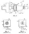
- FIG. 2 is a side plan view of the mini gas valve assembly shown in FIG. 1;
- FIG. 3 is a cross-sectional view of the valve assembly taken along the line 3-3 of FIG. 2;
- FIG. 4 is a cross-sectional view of the valve assembly taken along the line 4-4 of FIG. 2;
- FIG. 5 is an alternate perspective view of a mini gas valve assembly according to one aspect of the present invention.
- FIG. 6 is a front plan view of the mini gas valve assembly shown in FIG. 5;
- FIG. 7 is a cross-sectional view of the mini gas valve assembly taken along the line 7-7 of FIG. 5;
- FIG. 8 is a top plan view of the mini gas valve assembly shown in FIG. 5;
- FIG. 9 is a perspective view of a valve stem according to one aspect of the present invention.
- FIG. 10 is a side plan view of the valve stem shown in FIG. 9;
- FIG. 11 is a modified top view of the valve stem shown in FIG. 9 according to an alternate embodiment of the present invention.
- FIG. 12 is a front plan view of the valve stem shown in FIG. 9;
- FIG. 13 is an enlarged view of FIG. 12.
- FIG. 14 is a cross sectional view of the valve stem taken along the line 14-14 of FIG. 12.
- Typical gas supply systems include a plurality of gas valves, manifolds, air/fuel mixing tubes, and burner units.
- a mini gas valve assembly is shown in accordance with the present invention and is designated by the reference number 20.
- the gas valve assembly 20 includes a main valve body 22 having a first port 24, or inlet, a second port 26, or outlet, and a fluid passage enabling fluid communication between the first and second ports 24, 26.
- a valve stem 28 is provided for a user to selectively rotate a valve member 31 that controls the gradient fluid flow between fully on and off positions.
- the first and second ports 24, 26 are integral extensions of the main valve body 22.
- the main valve body 22 is preferably made of a metal material, such as aluminum, by appropriate casting or forging methods.
- Various ports, passages, and bores can be formed in the main valve body 22 using drilling operations known to one skilled in the art.
- the ports can be shaped having flattened regions 21 and provided with apertures 23 as desired.
- certain ports and other areas can be provided with one or more threaded portions 27 for connection to various manifolds, gas tubing, and other connecting devices.
- Recessed areas 25 may also be provided to house gaskets or other sealing members (not shown).
- a fully assembled mini gas valve assembly 20 will preferably include a detachable control knob 36 to rotate the valve stem 28.
- a detachable ignition switch 37 is provided to enable electronic ignition of a burner unit when the valve stem is rotated to a specific location.
- the ignition switch 37 removably attaches to the main valve body 22.
- the main valve body 22 provides a bore 30, or cavity, for receiving a valve member 31 or other valve components.
- the valve components can include any of several valve components as known in the art operable to selectively control fluid flow between the first and second ports 24, 26. It is appreciated by one skilled in the art, however, that the use of an annular tapered groove component may provide numerous advantages as compared to other valve designs. In particular, there is added flexibility in providing a desired control as well as simple manufacture. Additionally, if the valve member 31 wears over time, it will continue to provide an adequate seal between various ports disposed in the bore 30.
- the bore 30 is configured to retain an annular plug type valve member 31 that provides selective fluid communication between the first and second ports 24, 26.
- the plug valve member has a body portion that is generally cylindrical or conical in shape such that the exterior of the body portion matches the interior of the bore 30 and valve body 22.
- the valve member 31 includes at least one radially extending aperture (not shown) capable of being positioned in selective alignment with a first port area 29, providing fluid communication to the second port 26.
- valve stem 28 is disposed adjacent to the valve member 31 for rotating the valve member 31 within the bore 30 of the main valve body 22 and is described in more detail below.
- main valve body 22 can be configured differently to accommodate various types of inlet 24 and outlet 26 configurations as well as mounting arrangements.
- valve stem 28 is secured in place with a retaining cover plate 32 that clamps to the main valve body 22 with mechanical fasteners 34, such as screws.
- the retaining cover plate 32 includes an upstanding shoulder portion 33 for added support and to minimize radial movement of the valve stem 28.
- the valve stem 28 is hollow and defines an opening 38 extending the entire length of the stem.
- the valve stem 28 has a flattened section 40 operable to provide increased torque strength while providing an anti-rotation feature to minimize any misalignment between the valve stem 28 and a control knob 36 or ignition switch 37.
- a spring mechanism (not shown) is provided in the main valve body 22 to coordinate with the valve stem 28 such that the valve stem 28 must be depressed prior to rotating the valve member 31 out from the off position.
- a suitable spring seat or stop means such as a locking clip, may be provided so as to not over compress the spring.
- valve stem 28 of the present invention will now be described in greater detail.
- the valve stem 28 is provided with a base section 42 having at least one tab locking mechanism, such as a locking tab member 44.
- a locking tab member 44 can be configured with numerous stops, notches, tangs, or protrusions that may limit rotation of the valve member 31, thereby allowing the valve stem 28 to be locked at different positions, such as low, medium, and high.
- This particular embodiment allows for multiple operating conditions by simple rotation of a valve stem 28. In this instance, the valve stem would have to be slightly depressed in order to move the valve stem from the various locked positions. For example, once the locking tab 44 is out of a safety notch, the valve stem 28 can be freely rotated from the lowest setting to a fully open position.
- the base section 42 of the valve stem further includes a pair of projecting tabs 46 diametrically opposed from one another that are configured to mate with respective notches (not shown) on the valve member 31 providing coordinated movement therewith.
- the valve stem 28 is zinc coated cold rolled steel. In certain embodiments, the valve stem comprises stainless steel. Depending on the material selection, it may be desirable to heat treat the valve stem 28 for additional strength. Preferably, the valve stem is heat treated to a hardness of from about 40 to about 55 using the Rockwell C hardness scale. In certain embodiments, the hardness is greater than 55. It should be appreciated to one skilled in the art that many different methods exist for measuring the equivalent hardness of a material, all of which are included within the scope of the present invention. Regardless of heat treatment, the valve stem 28 of the present invention is operable to withstand at least about 50 in-lbs of torque without exhibiting permanent plastic deformation.
- valve stem 28 withstands between about 50 to about 60 in-lbs of torque, and more preferably between about 50 to about 70 in-lbs or torque without exhibiting plastic deformation. Most preferably, the valve stem 28 is operable to withstand a torque level greater than 70 in-lbs of torque. It should understood however, that other components that interact with the valve stem, such as notches, tabs, or stops provided in the retaining cover plate 32, should also be designed and suitably configured to withstand an equivalent amount of torque without exhibiting failure or severe deformation.
- the valve stem of the present invention has a wall thickness, ⁇ , of less than about 0.045 inches, and preferably from about 0.03 to about 0.045 inches.
- the valve stem can be provided with a wall thickness of less than about 0.03 inches as long as the stem provides the proper strength.
- Typical mini gas valve assemblies are provided with a valve stem having an outside diameter of about 0.25 inches or less.
- An overall length of the valve stem can vary depending upon the end use, and the lengths can be custom sized as desired.
- the valve stem has a substantially circular cross-section in an area 41 near the base member 42 to match and correspond with the shoulder region 33 of the retaining cover plate 32.
- the exposed portion of the valve stem 28 has a flattened portion 40 extending a length L proximal to the main valve body 22 to an opposite distal end 45 of the valve stem.
- the valve stem includes a flattened portion 40 that partially extends a length of the valve stem 28 and is adjacent to a cut-out section 43.
- the cut-out section 43 can be a variety of different lengths. In various embodiments, the cut-out section 43 provides an alternate mating surface for a control knob 36, or the like.
- the present invention further provides control means for fine-tune adjustments to a rate of fluid flow for valve assemblies that are equipped with specific flow settings, such as high and low.
- the control means includes an adjustment plug 35 member rotatably disposed in the valve member 31.
- the adjustment feature of the plug 35 is accessible through the aperture 38 of the valve stem 28 by using an instrument such as a thin bladed screw driver. This feature allows for adjustment of the flow through at least one of the first and second ports 24, 26.
Abstract
Description
- The present invention relates to valve assemblies, and more particularly, to a valve assembly for use with gaseous fluids.
- It is generally well known in the art to have a gas valve assembly that includes a combination of a valve body, a valve member, and a rotatable valve stem to control the flow of a fuel, or other gas, from an inlet source to an outlet. Contemporary mini gas valve assemblies are increasing in popularity and are being used with various appliances, such as gas ranges, outdoor barbeques, camp stoves, etc. The valve stems are typically made of brass or steel and currently have a 0.25 inch outside diameter valve stem.
- One difference, however, is that these smaller diameter valve stems do not provide as much torsional strength as the older valve assemblies having larger diameter valve stems. In certain instances, mini gas valve assemblies exhibit valve stem deformation with as little as 25 to 35 in-lbs of torque, with permanent plastic deformation beginning with about 40 in-lbs. The present invention provides a cost effective mini gas valve assembly having increased valve stem torque strength.
- In one aspect, the present invention provides a mini gas valve assembly having a main valve body including a first port, a second port, and a fluid passage providing fluid communication between the first and second ports. A valve member is disposed within a cavity in the main valve body and is configured to selectively adjust fluid flow between the first and second ports. A thin-walled, hollow valve stem is provided that is secured to the main valve body adjacent the valve member and configured for coordinated rotational movement with the valve member. The valve stem has a flattened portion extending a length proximal to the main valve body to an opposite distal end of the valve stem. Preferably, the valve stem is operable to withstand at least 50 in-lbs of torque without exhibiting plastic deformation. In one aspect, the present invention provides a valve stem that is heat treated having a Rockwell C hardness of from about 40 to about 55. Preferably, the valve stem is provided having a wall thickness of between about 0.03 to about 0.045 inches.
- In certain embodiments, the gas valve assembly is further provided with an adjustment plug member rotatably disposed in the main valve body and accessible through the hollow valve stem for adjusting low flow rates through one of the first and second ports.
- Further areas of applicability of the present invention will become apparent from the detailed description provided hereinafter. It should be understood that the detailed description and specific examples, while indicating the preferred embodiment of the invention, are intended for purposes of illustration only and are not intended to limit the scope of the invention.
- The present invention will become more fully understood from the detailed description and the accompanying drawings, wherein:
- FIG. 1 is a perspective view of a fully assembled mini gas valve assembly according to the principles of the present invention;
- FIG. 2 is a side plan view of the mini gas valve assembly shown in FIG. 1;
- FIG. 3 is a cross-sectional view of the valve assembly taken along the line 3-3 of FIG. 2;
- FIG. 4 is a cross-sectional view of the valve assembly taken along the line 4-4 of FIG. 2;
- FIG. 5 is an alternate perspective view of a mini gas valve assembly according to one aspect of the present invention;
- FIG. 6 is a front plan view of the mini gas valve assembly shown in FIG. 5;
- FIG. 7 is a cross-sectional view of the mini gas valve assembly taken along the line 7-7 of FIG. 5;
- FIG. 8 is a top plan view of the mini gas valve assembly shown in FIG. 5;
- FIG. 9 is a perspective view of a valve stem according to one aspect of the present invention;
- FIG. 10 is a side plan view of the valve stem shown in FIG. 9;
- FIG. 11 is a modified top view of the valve stem shown in FIG. 9 according to an alternate embodiment of the present invention;
- FIG. 12 is a front plan view of the valve stem shown in FIG. 9;
- FIG. 13 is an enlarged view of FIG. 12; and
- FIG. 14 is a cross sectional view of the valve stem taken along the line 14-14 of FIG. 12.
- The following description of the preferred embodiment(s) is merely exemplary in nature and is in no way intended to limit the invention, its application, or uses.
- Typical gas supply systems include a plurality of gas valves, manifolds, air/fuel mixing tubes, and burner units. Referring to Figures 1 and 2, a mini gas valve assembly is shown in accordance with the present invention and is designated by the
reference number 20. Thegas valve assembly 20 includes amain valve body 22 having afirst port 24, or inlet, asecond port 26, or outlet, and a fluid passage enabling fluid communication between the first andsecond ports valve stem 28 is provided for a user to selectively rotate avalve member 31 that controls the gradient fluid flow between fully on and off positions. - In preferred embodiments, the first and
second ports main valve body 22. Themain valve body 22 is preferably made of a metal material, such as aluminum, by appropriate casting or forging methods. Various ports, passages, and bores can be formed in themain valve body 22 using drilling operations known to one skilled in the art. The ports can be shaped havingflattened regions 21 and provided withapertures 23 as desired. As illustrated, certain ports and other areas can be provided with one or more threadedportions 27 for connection to various manifolds, gas tubing, and other connecting devices. Recessedareas 25 may also be provided to house gaskets or other sealing members (not shown). - A fully assembled mini
gas valve assembly 20 will preferably include adetachable control knob 36 to rotate thevalve stem 28. In certain embodiments, adetachable ignition switch 37 is provided to enable electronic ignition of a burner unit when the valve stem is rotated to a specific location. In certain embodiments, the ignition switch 37 removably attaches to themain valve body 22. - The
main valve body 22 provides abore 30, or cavity, for receiving avalve member 31 or other valve components. The valve components can include any of several valve components as known in the art operable to selectively control fluid flow between the first andsecond ports valve member 31 wears over time, it will continue to provide an adequate seal between various ports disposed in thebore 30. - Thus, in one embodiment, the
bore 30 is configured to retain an annular plugtype valve member 31 that provides selective fluid communication between the first andsecond ports bore 30 andvalve body 22. Typically, thevalve member 31 includes at least one radially extending aperture (not shown) capable of being positioned in selective alignment with afirst port area 29, providing fluid communication to thesecond port 26. - The
valve stem 28 is disposed adjacent to thevalve member 31 for rotating thevalve member 31 within thebore 30 of themain valve body 22 and is described in more detail below. It should be appreciated that themain valve body 22 can be configured differently to accommodate various types ofinlet 24 andoutlet 26 configurations as well as mounting arrangements. For example, while the figures depict theinlet 24 andoutlet 26 ports substantially perpendicular to one another, it is contemplated that their spatial relationship can include a wide array of alternate variations. - As shown in Figures 5-8, the
valve stem 28 is secured in place with aretaining cover plate 32 that clamps to themain valve body 22 withmechanical fasteners 34, such as screws. Preferably, theretaining cover plate 32 includes anupstanding shoulder portion 33 for added support and to minimize radial movement of thevalve stem 28. Thevalve stem 28 is hollow and defines anopening 38 extending the entire length of the stem. Preferably, thevalve stem 28 has aflattened section 40 operable to provide increased torque strength while providing an anti-rotation feature to minimize any misalignment between thevalve stem 28 and acontrol knob 36 orignition switch 37. - In preferred embodiments, a spring mechanism (not shown) is provided in the
main valve body 22 to coordinate with thevalve stem 28 such that thevalve stem 28 must be depressed prior to rotating thevalve member 31 out from the off position. A suitable spring seat or stop means, such as a locking clip, may be provided so as to not over compress the spring. - With reference to Figures 9-14, the
valve stem 28 of the present invention will now be described in greater detail. - In various preferred embodiments, the
valve stem 28 is provided with abase section 42 having at least one tab locking mechanism, such as alocking tab member 44. It should be appreciated that the retainingcover plate 32 can be configured with numerous stops, notches, tangs, or protrusions that may limit rotation of thevalve member 31, thereby allowing thevalve stem 28 to be locked at different positions, such as low, medium, and high. This particular embodiment allows for multiple operating conditions by simple rotation of avalve stem 28. In this instance, the valve stem would have to be slightly depressed in order to move the valve stem from the various locked positions. For example, once the lockingtab 44 is out of a safety notch, thevalve stem 28 can be freely rotated from the lowest setting to a fully open position. In preferred embodiments, thebase section 42 of the valve stem further includes a pair of projectingtabs 46 diametrically opposed from one another that are configured to mate with respective notches (not shown) on thevalve member 31 providing coordinated movement therewith. - In preferred embodiments, the
valve stem 28 is zinc coated cold rolled steel. In certain embodiments, the valve stem comprises stainless steel. Depending on the material selection, it may be desirable to heat treat thevalve stem 28 for additional strength. Preferably, the valve stem is heat treated to a hardness of from about 40 to about 55 using the Rockwell C hardness scale. In certain embodiments, the hardness is greater than 55. It should be appreciated to one skilled in the art that many different methods exist for measuring the equivalent hardness of a material, all of which are included within the scope of the present invention. Regardless of heat treatment, thevalve stem 28 of the present invention is operable to withstand at least about 50 in-lbs of torque without exhibiting permanent plastic deformation. Preferably thevalve stem 28 withstands between about 50 to about 60 in-lbs of torque, and more preferably between about 50 to about 70 in-lbs or torque without exhibiting plastic deformation. Most preferably, thevalve stem 28 is operable to withstand a torque level greater than 70 in-lbs of torque. It should understood however, that other components that interact with the valve stem, such as notches, tabs, or stops provided in the retainingcover plate 32, should also be designed and suitably configured to withstand an equivalent amount of torque without exhibiting failure or severe deformation. - As in Figure 14, the valve stem of the present invention has a wall thickness, δ, of less than about 0.045 inches, and preferably from about 0.03 to about 0.045 inches. In certain embodiments, the valve stem can be provided with a wall thickness of less than about 0.03 inches as long as the stem provides the proper strength. Typical mini gas valve assemblies are provided with a valve stem having an outside diameter of about 0.25 inches or less. An overall length of the valve stem can vary depending upon the end use, and the lengths can be custom sized as desired.
- In various embodiments, the valve stem has a substantially circular cross-section in an
area 41 near thebase member 42 to match and correspond with theshoulder region 33 of the retainingcover plate 32. Thus, once assembled, the exposed portion of thevalve stem 28 has a flattenedportion 40 extending a length L proximal to themain valve body 22 to an oppositedistal end 45 of the valve stem. As shown in Figure 11, in certain embodiments the valve stem includes a flattenedportion 40 that partially extends a length of thevalve stem 28 and is adjacent to a cut-outsection 43. The cut-outsection 43 can be a variety of different lengths. In various embodiments, the cut-outsection 43 provides an alternate mating surface for acontrol knob 36, or the like. - In certain embodiments, the present invention further provides control means for fine-tune adjustments to a rate of fluid flow for valve assemblies that are equipped with specific flow settings, such as high and low. In one preferred embodiment as shown in Figure 7, the control means includes an
adjustment plug 35 member rotatably disposed in thevalve member 31. Preferably, the adjustment feature of theplug 35 is accessible through theaperture 38 of thevalve stem 28 by using an instrument such as a thin bladed screw driver. This feature allows for adjustment of the flow through at least one of the first andsecond ports - The description of the invention is merely exemplary in nature and, thus, variations that do not depart from the gist of the invention are intended to be within the scope of the invention. Such variations are not to be regarded as a departure from the spirit and scope of the invention.
Claims (22)
- A valve, comprising:a main valve body having a first port, a second port, and a fluid passage providing fluid communication between the first and second ports;a valve member disposed within the main valve body and configured to selectively adjust fluid flow between the first and second ports; anda thin-walled, hollow valve stem secured to the main valve body adjacent the valve member and configured for rotating the valve member, the valve stem having a flattened portion extending a length from proximal to the main valve body to an opposite distal end of the valve stem,wherein the valve stem is operable to withstand at least 50 in-lbs of torque without exhibiting plastic deformation.
- The valve according to claim 1, wherein the valve stem is operable to withstand at least 70 in-lbs of torque without exhibiting plastic deformation.
- The valve according to claim 1, wherein the valve stem is heat treated.
- The valve according to claim 3, wherein the valve stem is heat treated having a Rockwell C hardness of from about 40 to about 55.
- The valve according to claim 1, wherein the valve stem has a wall thickness less than about 0.045 inches.
- The valve according to claim 1, wherein the valve stem has a wall thickness from about 0.03 to about 0.045 inches.
- The valve according to claim 1, further comprising an ignition switch assembly detachably secured to the valve assembiy.
- The valve according to claim 1, further comprising a control knob detachably secured to the valve stem.
- The valve according to claim 1, further comprising a cover plate securing the valve stem to the main valve body.
- The valve according to claim 1, wherein the valve stem comprises zinc plated cold rolled steel.
- The valve according to claim 1, wherein the valve stem comprises at least one projecting tab member configured to provide coordinated rotational movement with the valve member.
- The valve according to claim 1, further comprising an adjustment plug member rotatably disposed in the main valve body and accessible through the hollow valve stem, the plug member providing means for fine-tune adjustment of a rate of fluid flow through at least one of the first and second ports.
- The valve according to claim 1, wherein the valve stem comprises a first section having a flattened area and a second section having a cut-out area.
- The valve according to claim 1, further comprising a tab locking mechanism requiring depression of the valve stem prior to any rotary movement.
- The valve according to claim 1, wherein the valve stem has an outside diameter of about 0.25 inches or less.
- A gas valve assembly, comprising:a main valve body having a cavity, the main valve body including an inlet port and an outlet port disposed perpendicular to one another and in fluid communication, the inlet and outlet ports being continuous, integral extensions of the main valve body;a valve member rotatably disposed within the cavity and configured to selectively adjust fluid flow between the first and second ports; anda hollow valve stem secured to the main valve body adjacent the valve member and configured for coordinated rotating movement with the valve member, the valve stem having a wall thickness of from about 0.03 to about 0.045 inches and having a flattened portion providing an anti-rotation surface extending a length proximal to the main valve body to an opposite distal end of the valve stem.
- The gas valve assembly according to claim 16, wherein the flattened portion partially extends along a length of the valve stem and is adjacent to a cut-out section, the cut-out section being operable to mate with a control knob.
- The gas valve assembly according to claim 16, wherein the valve stem is heat treated having a Rockwell C hardness of from about 40 to about 55.
- The gas valve assembly according to claim 16, wherein the valve stem is operable to withstand a torque of at least 50 in-lbs without exhibiting plastic deformation.
- The gas valve assembly according to claim 19, wherein the valve stem is operable to withstand a torque of at least 70 in-lbs without exhibiting plastic deformation.
- A gas valve assembly, comprising:a main valve body having a cavity, the main valve body including an inlet port and an outlet port disposed perpendicular to one another and in fluid communication, the inlet and outlet ports being continuous, integral extensions of the main valve body;a conical shaped valve member rotatably disposed within the cavity and configured to selectively adjust fluid flow between the first and second ports; anda hollow valve stem secured to the main valve body adjacent the valve member and configured for coordinated rotating movement with the valve member, the valve stem having a wall thickness less than about 0.045 inches and a Rockwell C hardness of from about 40 to about 55, the hollow valve stem further comprising a flattened portion providing an anti-rotation surface and operable to withstand at least 50 lb-in of torque without exhibiting plastic deformation.
- The gas valve assembly according to claim 21, further comprising an adjustment plug member rotatably disposed in the main valve body and accessible through the hollow valve stem, the plug member providing means for fine-tune adjustment of a rate of fluid flow.
Applications Claiming Priority (1)
| Application Number | Priority Date | Filing Date | Title |
|---|---|---|---|
| US11/178,775 US20070007482A1 (en) | 2005-07-11 | 2005-07-11 | Mini gas valve stem |
Publications (1)
| Publication Number | Publication Date |
|---|---|
| EP1744085A1 true EP1744085A1 (en) | 2007-01-17 |
Family
ID=37192305
Family Applications (1)
| Application Number | Title | Priority Date | Filing Date |
|---|---|---|---|
| EP06253623A Withdrawn EP1744085A1 (en) | 2005-07-11 | 2006-07-11 | Valve stem |
Country Status (2)
| Country | Link |
|---|---|
| US (1) | US20070007482A1 (en) |
| EP (1) | EP1744085A1 (en) |
Cited By (5)
| Publication number | Priority date | Publication date | Assignee | Title |
|---|---|---|---|---|
| EP1777457A3 (en) * | 2006-01-05 | 2008-06-04 | Turas Gas Armatures R&D | Pressure spring for taps with adjustment screw |
| WO2016095005A1 (en) * | 2014-12-17 | 2016-06-23 | Whirlpool S.A. | Gas supply system with fine flow rate adjustement for electrical home appliances, and control knob for said gas supply system |
| WO2016095004A1 (en) * | 2014-12-17 | 2016-06-23 | Whirlpool S.A. | Gas supply system with flow rate booster for electrical home appliances, and control knob for said gas supply system |
| EP3091287A1 (en) * | 2015-05-07 | 2016-11-09 | Application des Gaz | Control device for igniting and adjusting a flow of gas |
| EP3104051A1 (en) | 2015-06-10 | 2016-12-14 | Turas Gaz Armatürleri Sanayi. Ve Ticaret A.S. | Handle for a gas tap |
Families Citing this family (5)
| Publication number | Priority date | Publication date | Assignee | Title |
|---|---|---|---|---|
| US7967005B2 (en) * | 2007-04-13 | 2011-06-28 | Daniel Parrish | Dual fuel gas valve and gas grill |
| CN105179856A (en) * | 2015-08-10 | 2015-12-23 | 江苏盛纳凯尔医用科技有限公司 | T-branch pipe structure |
| CN105351104B (en) * | 2015-12-08 | 2018-08-21 | 重庆润通科技有限公司 | Oil-gas two-way integrated switch |
| US11085645B2 (en) * | 2018-05-31 | 2021-08-10 | Haier Us Appliance Solutions, Inc. | Eductor for a gas cooktop appliance |
| US11473779B2 (en) | 2019-11-19 | 2022-10-18 | Electrolux Home Products, Inc. | Gas valve for a cooktop appliance |
Citations (6)
| Publication number | Priority date | Publication date | Assignee | Title |
|---|---|---|---|---|
| US2590550A (en) * | 1945-08-09 | 1952-03-25 | Harper Wyman Co | Gas valve |
| US2683465A (en) * | 1951-07-18 | 1954-07-13 | Ervin H Mueller | Valve with position indicating means |
| US2763289A (en) * | 1952-11-17 | 1956-09-18 | Ervin H Mueller | Double outlet valve for controlling gas |
| US3292660A (en) * | 1963-10-14 | 1966-12-20 | W J Schoenberger Co | Gas valve |
| WO2001033118A1 (en) * | 1999-11-02 | 2001-05-10 | Fisher & Paykel Appliances Limited | A gas valve |
| US20040238049A1 (en) * | 2003-05-28 | 2004-12-02 | Wuu-Hung Lin | Gas regulating valve |
Family Cites Families (11)
| Publication number | Priority date | Publication date | Assignee | Title |
|---|---|---|---|---|
| US98455A (en) * | 1869-12-28 | Improvement in machines for boring blind-stiles | ||
| US2554470A (en) * | 1947-07-05 | 1951-05-22 | Ervin H Mueller | Valve for controlling gas |
| US4395018A (en) * | 1980-07-30 | 1983-07-26 | Stanadyne, Inc. | Valve member with fixed seal shutoff |
| US4614661A (en) * | 1985-03-21 | 1986-09-30 | Kraft, Inc. | Methods and apparatus for sanitary steam injection |
| US4947891A (en) * | 1987-07-15 | 1990-08-14 | Robertshaw Controls Company | Fuel control device, fuel control system using the device and method of making the device |
| US4870314A (en) * | 1987-11-23 | 1989-09-26 | The Coleman Company, Inc. | Cam-actuated piezoelectric ignition device for gas appliance |
| US6670553B1 (en) * | 1998-01-15 | 2003-12-30 | Arlington Industries, Inc. | Snap engagement electrical fitting for EMT |
| AU767055B2 (en) * | 1998-05-06 | 2003-10-30 | Zbb Technologies Inc. | Spill and leak containment system for zinc-bromine battery |
| US6375150B1 (en) * | 1999-06-18 | 2002-04-23 | Comercial Acros Whirlpool, S.A. De C.V. | Knob for gas apparatus with safety button |
| US6394081B1 (en) * | 1999-06-18 | 2002-05-28 | Comercial Acros Whirlpool, S.A. De C.V. | Safety knob for domestic gas apparatuses |
| AUPQ214099A0 (en) * | 1999-08-09 | 1999-09-02 | Advanced Products Pty Ltd | Gas control assembly |
-
2005
- 2005-07-11 US US11/178,775 patent/US20070007482A1/en not_active Abandoned
-
2006
- 2006-07-11 EP EP06253623A patent/EP1744085A1/en not_active Withdrawn
Patent Citations (6)
| Publication number | Priority date | Publication date | Assignee | Title |
|---|---|---|---|---|
| US2590550A (en) * | 1945-08-09 | 1952-03-25 | Harper Wyman Co | Gas valve |
| US2683465A (en) * | 1951-07-18 | 1954-07-13 | Ervin H Mueller | Valve with position indicating means |
| US2763289A (en) * | 1952-11-17 | 1956-09-18 | Ervin H Mueller | Double outlet valve for controlling gas |
| US3292660A (en) * | 1963-10-14 | 1966-12-20 | W J Schoenberger Co | Gas valve |
| WO2001033118A1 (en) * | 1999-11-02 | 2001-05-10 | Fisher & Paykel Appliances Limited | A gas valve |
| US20040238049A1 (en) * | 2003-05-28 | 2004-12-02 | Wuu-Hung Lin | Gas regulating valve |
Cited By (6)
| Publication number | Priority date | Publication date | Assignee | Title |
|---|---|---|---|---|
| EP1777457A3 (en) * | 2006-01-05 | 2008-06-04 | Turas Gas Armatures R&D | Pressure spring for taps with adjustment screw |
| WO2016095005A1 (en) * | 2014-12-17 | 2016-06-23 | Whirlpool S.A. | Gas supply system with fine flow rate adjustement for electrical home appliances, and control knob for said gas supply system |
| WO2016095004A1 (en) * | 2014-12-17 | 2016-06-23 | Whirlpool S.A. | Gas supply system with flow rate booster for electrical home appliances, and control knob for said gas supply system |
| EP3091287A1 (en) * | 2015-05-07 | 2016-11-09 | Application des Gaz | Control device for igniting and adjusting a flow of gas |
| FR3035782A1 (en) * | 2015-05-07 | 2016-11-11 | Applic Gaz Sa | CONTROL DEVICE FOR IGNITING AND ADJUSTING A GAS FLOW |
| EP3104051A1 (en) | 2015-06-10 | 2016-12-14 | Turas Gaz Armatürleri Sanayi. Ve Ticaret A.S. | Handle for a gas tap |
Also Published As
| Publication number | Publication date |
|---|---|
| US20070007482A1 (en) | 2007-01-11 |
Similar Documents
| Publication | Publication Date | Title |
|---|---|---|
| EP1744085A1 (en) | Valve stem | |
| US9915367B2 (en) | Valve assembly having improved rotational feel | |
| CA2601987C (en) | Rotary valve arranged in a multi-gas cooker | |
| EP1793299B1 (en) | Dual gas pressure regulator for a household appliance | |
| US8297317B2 (en) | Gas valve with dual outlets | |
| US11592115B2 (en) | Fluid valve | |
| EP3211309A1 (en) | Regulating valve for a gas cooking appliance and gas cooking appliance incorporating said regulating valve | |
| US20100127202A1 (en) | Valve body | |
| US5836296A (en) | Manifold with integral burner control and oven control | |
| US6837480B1 (en) | Ball valve with adjustable flow coefficient | |
| WO2009006893A1 (en) | A control valve | |
| EP1795789A2 (en) | Reinforced gas valve stem | |
| KR890000449B1 (en) | Fluid control valve | |
| US5960830A (en) | Faucet assembly | |
| EP3521701B1 (en) | Gas cock with a safety valve for a gas cooking appliance, and gas cooking appliance incorporating said gas cock | |
| US2694412A (en) | Multiposition fluid valve | |
| CN113614450B (en) | Gas valve and gas furnace | |
| US11920330B2 (en) | Method of manufacturing a tap body | |
| JPH07119848A (en) | Ball valve type stop cock capable of adjusting flow rate | |
| EP1387115B1 (en) | Faucet having a delivery barrel arranged at the top of the faucet body | |
| WO1997030314A1 (en) | Manifold with integral burner control and oven control | |
| GB2388888A (en) | Hydraulic diverter valve | |
| GB2388887A (en) | Hydraulic diverter valve |
Legal Events
| Date | Code | Title | Description |
|---|---|---|---|
| PUAI | Public reference made under article 153(3) epc to a published international application that has entered the european phase |
Free format text: ORIGINAL CODE: 0009012 |
|
| AK | Designated contracting states |
Kind code of ref document: A1 Designated state(s): AT BE BG CH CY CZ DE DK EE ES FI FR GB GR HU IE IS IT LI LT LU LV MC NL PL PT RO SE SI SK TR |
|
| AX | Request for extension of the european patent |
Extension state: AL BA HR MK YU |
|
| 17P | Request for examination filed |
Effective date: 20070516 |
|
| 17Q | First examination report despatched |
Effective date: 20070615 |
|
| AKX | Designation fees paid |
Designated state(s): AT BE BG CH CY CZ DE DK EE ES FI FR GB GR HU IE IS IT LI LT LU LV MC NL PL PT RO SE SI SK TR |
|
| STAA | Information on the status of an ep patent application or granted ep patent |
Free format text: STATUS: THE APPLICATION IS DEEMED TO BE WITHDRAWN |
|
| 18D | Application deemed to be withdrawn |
Effective date: 20090616 |