EP1744045A1 - Methods and apparatus for assembling gas turbine engines - Google Patents
Methods and apparatus for assembling gas turbine engines Download PDFInfo
- Publication number
- EP1744045A1 EP1744045A1 EP06252376A EP06252376A EP1744045A1 EP 1744045 A1 EP1744045 A1 EP 1744045A1 EP 06252376 A EP06252376 A EP 06252376A EP 06252376 A EP06252376 A EP 06252376A EP 1744045 A1 EP1744045 A1 EP 1744045A1
- Authority
- EP
- European Patent Office
- Prior art keywords
- airflow
- bypass duct
- nozzle
- bypass
- core
- Prior art date
- Legal status (The legal status is an assumption and is not a legal conclusion. Google has not performed a legal analysis and makes no representation as to the accuracy of the status listed.)
- Granted
Links
Images


Classifications
-
- F—MECHANICAL ENGINEERING; LIGHTING; HEATING; WEAPONS; BLASTING
- F02—COMBUSTION ENGINES; HOT-GAS OR COMBUSTION-PRODUCT ENGINE PLANTS
- F02K—JET-PROPULSION PLANTS
- F02K1/00—Plants characterised by the form or arrangement of the jet pipe or nozzle; Jet pipes or nozzles peculiar thereto
- F02K1/04—Mounting of an exhaust cone in the jet pipe
-
- F—MECHANICAL ENGINEERING; LIGHTING; HEATING; WEAPONS; BLASTING
- F02—COMBUSTION ENGINES; HOT-GAS OR COMBUSTION-PRODUCT ENGINE PLANTS
- F02K—JET-PROPULSION PLANTS
- F02K1/00—Plants characterised by the form or arrangement of the jet pipe or nozzle; Jet pipes or nozzles peculiar thereto
- F02K1/78—Other construction of jet pipes
-
- F—MECHANICAL ENGINEERING; LIGHTING; HEATING; WEAPONS; BLASTING
- F02—COMBUSTION ENGINES; HOT-GAS OR COMBUSTION-PRODUCT ENGINE PLANTS
- F02K—JET-PROPULSION PLANTS
- F02K3/00—Plants including a gas turbine driving a compressor or a ducted fan
- F02K3/02—Plants including a gas turbine driving a compressor or a ducted fan in which part of the working fluid by-passes the turbine and combustion chamber
- F02K3/04—Plants including a gas turbine driving a compressor or a ducted fan in which part of the working fluid by-passes the turbine and combustion chamber the plant including ducted fans, i.e. fans with high volume, low pressure outputs, for augmenting the jet thrust, e.g. of double-flow type
-
- F—MECHANICAL ENGINEERING; LIGHTING; HEATING; WEAPONS; BLASTING
- F02—COMBUSTION ENGINES; HOT-GAS OR COMBUSTION-PRODUCT ENGINE PLANTS
- F02K—JET-PROPULSION PLANTS
- F02K3/00—Plants including a gas turbine driving a compressor or a ducted fan
- F02K3/02—Plants including a gas turbine driving a compressor or a ducted fan in which part of the working fluid by-passes the turbine and combustion chamber
- F02K3/04—Plants including a gas turbine driving a compressor or a ducted fan in which part of the working fluid by-passes the turbine and combustion chamber the plant including ducted fans, i.e. fans with high volume, low pressure outputs, for augmenting the jet thrust, e.g. of double-flow type
- F02K3/075—Plants including a gas turbine driving a compressor or a ducted fan in which part of the working fluid by-passes the turbine and combustion chamber the plant including ducted fans, i.e. fans with high volume, low pressure outputs, for augmenting the jet thrust, e.g. of double-flow type controlling flow ratio between flows
-
- F—MECHANICAL ENGINEERING; LIGHTING; HEATING; WEAPONS; BLASTING
- F02—COMBUSTION ENGINES; HOT-GAS OR COMBUSTION-PRODUCT ENGINE PLANTS
- F02K—JET-PROPULSION PLANTS
- F02K3/00—Plants including a gas turbine driving a compressor or a ducted fan
- F02K3/02—Plants including a gas turbine driving a compressor or a ducted fan in which part of the working fluid by-passes the turbine and combustion chamber
- F02K3/04—Plants including a gas turbine driving a compressor or a ducted fan in which part of the working fluid by-passes the turbine and combustion chamber the plant including ducted fans, i.e. fans with high volume, low pressure outputs, for augmenting the jet thrust, e.g. of double-flow type
- F02K3/077—Plants including a gas turbine driving a compressor or a ducted fan in which part of the working fluid by-passes the turbine and combustion chamber the plant including ducted fans, i.e. fans with high volume, low pressure outputs, for augmenting the jet thrust, e.g. of double-flow type the plant being of the multiple flow type, i.e. having three or more flows
Definitions
- the present invention relates to gas turbine engines and more particularly, to methods and apparatus to facilitate controlling gas turbine engine bypass airflows.
- At least one known gas turbine engine includes, in serial flow arrangement, a forward fan assembly, an aft fan assembly, a high-pressure compressor for compressing air flowing through the engine, a combustor for mixing fuel with the compressed air such that the mixture may be ignited, and a high pressure turbine.
- the high-pressure compressor, combustor and high-pressure turbine are sometimes collectively referred to as the core engine.
- the core engine In operation, the core engine generates combustion gases which are discharged downstream to a low pressure turbine that extracts energy therefrom for powering the forward and aft fan assemblies.
- VCE variable cycle engine
- flow modulation potential is increased by splitting the fan into two sections, wherein each section is in flow communication with a separate concentric bypass duct surrounding the core engine.
- the bypass ratio i.e., the ratio of the quantity of airflow bypassing the core engine to the quantity of airflow passing through the core engine can be varied by selectively mixing or separating the bypass duct stream and the core engine exhaust stream through various systems valving and mixing systems.
- At least one known VCE includes a nozzle assembly that includes an internal nozzle valve or plug for controlling airflow through the bypass ducts. More specifically, in such engines, the internal plug is supported by a plurality of circumferentially spaced, radially extending support struts that are coupled to the outer duct structure of the engine. As such, because these support struts are positioned within the flow path of the exhausted core engine airflow, the support struts are exposed to high temperature airflows and may be subjected to large thermal gradients generated from the hot core engine airflow and the cool bypass airflow. Over time, the support struts may be prematurely fatigued of damaged due to continued exposure to high operating temperatures generated by the gas turbine engine.
- a method for operating a gas turbine engine including a core engine having a core stream duct, an inner bypass duct, an outer bypass duct, and a nozzle assembly downstream of the core engine and including a core engine nozzle and a bypass nozzle separated by a liner.
- the method includes channeling a first airflow discharged from the core gas turbine engine to the core engine nozzle, and channeling a second airflow through the inner bypass duct such that the second airflow bypasses the core gas turbine engine.
- the second airflow is channeled to a plurality of fairings that are positioned upstream from a plurality of support struts coupled to the nozzle assembly liner.
- the method also includes channeling a third airflow through the outer bypass duct such that the third airflow bypasses the core gas turbine engine, wherein the third airflow is channeled through the support struts to the bypass nozzle.
- a nozzle assembly for an engine including a core engine and at least one bypass duct for channeling airflow around the core engine.
- the nozzle assembly includes a liner comprising an inner surface and an outer surface, wherein the inner surface confines airflow within a nozzle bypass duct, and the outer surface confines airflow discharged from the core engine.
- a plurality of strut members are coupled to and support the liner.
- a plurality of fairings are in flow communication with the at least one bypass duct, and each fairing is upstream from a respective one of the plurality of strut members to facilitate directing a portion of the airflow from the bypass duct past the plurality of strut members.
- a gas turbine engine assembly including a core gas turbine engine including a core engine airflow stream, at least one core engine bypass duct channeling a bypass airflow stream therethrough, and a nozzle assembly downstream of the core engine and the at least one core engine bypass duct.
- the nozzle assembly includes a liner separating airflow discharged from the core engine from airflow within a nozzle bypass duct.
- a plurality of strut members are coupled to and support the liner, and a plurality of fairings are in flow communication with the at least one core engine bypass duct.
- Each of the plurality of fairings are positioned upstream from a respective one of the plurality of strut members and channel a portion of airflow from the core engine bypass duct to the plurality of strut members.
- FIG. 1 is a cross-sectional view of a portion of an exemplary gas turbine engine 10 that includes an outer casing 12 having an upstream end 13 that forms an inlet 14 sized to provide a predetermined quantity of airflow to the engine 10.
- Fan 16 Disposed within inlet 14 is a fan 16 for receiving and compressing airflow channeled through inlet 14.
- Fan 16 includes a forward section 18 that is axially displaced from an aft section 20 by an axial space 22.
- forward section 18 includes a pair of rows of rotor blades 24 and 26 that are interspaced between rows of inlet guide vanes 28 and stator vanes 30 and 32.
- aft fan section 20 includes at least one stage of rotor blades 34 that are interspaced between adjacent rows of aft fan stator vanes 36 and 38.
- Gas turbine engine 10 also includes a core engine 40 that is downstream of fan 16.
- core engine 40 includes an axial flow compressor 42 upstream of a combustor 44 and a high pressure turbine 46.
- Turbine 46 drives a rotor 48.
- air compressed by fan 16 is channeled through a core engine inlet duct 50, and is further compressed by axial flow compressor 42. Compressed air is then channeled to combustor 44 wherein fuel is injected to create high energy combustion gases used to drive core engine turbine 46, which, in turn, drives rotor 48 through a shaft 52. High temperature combustion gases are then routed to drive a low-pressure turbine 54 which, in turn, drives fan 16 through shaft 56.
- gas turbine engine 10 also includes an outer bypass duct 58 that is radially inward of outer casing 12, and an inner bypass duct 60 that is positioned radially inward of outer bypass duct 58.
- Ducts 58 and 60 enable a portion of fan airflow to bypass and flow around core engine 40.
- outer bypass duct 58 and inner bypass duct 60 each substantially circumscribe core gas turbine engine 10.
- engine 10 includes a single bypass duct.
- engine 10 includes another bypass duct, such as, for example, a flade duct (not shown).
- air is channeled from fan 16 and separated into a plurality of flowpaths 62. Specifically, a first portion of airflow is channeled through outer bypass duct 58 towards a nozzle assembly 100. A second portion of airflow is channeled through inner bypass duct 60, and radially inward of a splitter 70, toward a variable area bypass injector (VABI) 102. A third portion of airflow is channeled into core gas turbine engine 40. Accordingly, as described herein, the air discharged from fan 16 is separated into three separate flowpaths 62 within gas turbine engine 10. In alternative embodiments, more or less than three flowpaths 62.
- VABI variable area bypass injector
- VABI 102 facilitates combining and/or mixing at least a portion of airflow channeled through inner bypass duct 60 with core engine combustion gases exiting low-pressure turbine 54. The combined airflow is then channeled to nozzle assembly 100.
- the airflow channeled through inner bypass duct 60 is channeled to a hollow fairing 104 coupled aft of core gas turbine engine 10.
- airflow channeled through outer bypass duct 58 is channeled through a hollow strut 106 coupled aft of fairing 104.
- fairing 104 and strut 106 define VABI 102.
- bypass airflow from each of outer and inner bypass ducts 58 and 60 is exhausted into a nozzle bypass duct 108 via fairings 104 and struts 106, respectively.
- the bypass airflow is the exhausted from nozzle bypass duct 108 through nozzle assembly 100.
- an inner liner 110 defines an outer surface of nozzle bypass duct 108 and facilitates separating the airflow in nozzle bypass duct 108 from the combined airflow channeled downstream of VABI 102.
- inner liner 110 is supported by struts 106 and/or fairings 104.
- gas turbine engine 10 includes a core nozzle assembly 112, i.e. an annular core nozzle shroud, and a bypass nozzle assembly 114.
- Core nozzle assembly 112 facilitates regulating the quantity of airflow exhausted therethrough.
- airflow exhausted through core nozzle assembly includes the combined airflow channeled from VABI 102.
- Bypass nozzle assembly 114 facilitates regulating the quantity of airflow exhausted therethrough from nozzle bypass duct 108.
- nozzle assemblies 112 and 114 are separated by inner liner 110.
- core nozzle assembly 112 includes a core nozzle valve 120, i.e. an annular shroud, that is coupled to outer casing 12.
- valve 120 is an assembly of overlapping flaps and seals.
- core nozzle assembly 112 is a variable area core nozzle assembly wherein various mechanical devices actuate valve 120 to vary the size of a throat area 122.
- Throat area 122 is the minimum flow area defined between valve 120 and inner liner 110.
- core nozzle valve 120 may be actuated using a hinge (not shown).
- core nozzle valve 120 is translatable in an axially forward direction 124 and an axially aft direction 126.
- core nozzle valve 120 is fixedly coupled to outer casing 12.
- core nozzle valve 120 controls the size of throat area 122 to facilitate regulating a quantity of air channeled through throat area 122. More specifically, and in the exemplary embodiment, core nozzle valve 120 is translated in forward direction 124 to facilitate increasing a quantity of airflow that is channeled through throat area 122. Alternatively, core nozzle valve 120 is translated in aft direction 126 to facilitate reducing the quantity of airflow channeled through throat area 122.
- bypass nozzle assembly 114 includes a bypass nozzle valve 130, i.e. a plug, that is coupled to a portion of engine 10 such as a stationary engine structure.
- valve 130 is an assembly of flaps.
- bypass nozzle assembly 114 is a variable area nozzle wherein actuation is accomplished using various mechanical devices to vary the size of a throat area 134 defined between valve 130 and inner liner 110.
- bypass nozzle valve 130 may be actuated using a hinge (not shown).
- bypass nozzle valve 130 is translatable in axially forward direction 124 to and an axially aft direction 126.
- bypass nozzle valve 130 is fixedly coupled to an engine structure.
- bypass nozzle valve 130 is movable to facilitate regulating and/or varying a quantity of airflow channeled through throat area 134. More specifically, and in the exemplary embodiment, bypass nozzle valve 130 is translated in forward direction 124 to facilitate increasing a quantity of airflow that is channeled through throat area 134. Alternatively, bypass nozzle valve 130 is translated in aft direction 126 to facilitate reducing the quantity of airflow channeled through throat area 134. Accordingly, variable area nozzle valve 130 facilitates regulating the quantity of airflow that is channeled from bypass nozzle duct 108 to the exhaust without mixing with the gas turbine exhaust.
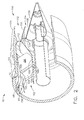
- FIG. 2 is a perspective view of nozzle assembly 100 for use with gas turbine engine 10
- Figure 3 is a perspective view of a portion of nozzle assembly 100.
- Nozzle assembly 100 includes core nozzle assembly 112 for exhausting core engine air and bypass air combined using VABI 102, and bypass nozzle assembly 114 for exhausting bypass air channeled through nozzle bypass duct 108.
- Inner liner 110 separates the airflows in each of core and bypass nozzle assemblies 112 and 114.
- inner liner 110 is supported by strut 106 and/or fairing 104.
- nozzle assembly 100 includes a plurality of circumferentially spaced apart, and radially extending hollow support struts 106.
- Each strut 106 extends between, and is coupled to, inner liner 110 at a base 150 of each strut 106 and duct structure, such as a duct liner 152, at an upper end 154 of each strut 106.
- each strut 106 is coupled to outer casing 12.
- each support strut 106 is integrally formed with one of inner liner 110 and/or duct liner 152.
- each strut 106 is in flow communication with outer bypass duct 58 at upper end 154, such that the bypass airflow is channeled through the hollow portion, or interior, of each strut 106.
- struts 106 are internally or convectively cooled by the bypass airflow.
- each strut 106 is also in flow communication with nozzle bypass duct 108 at base 150, such that the bypass airflow channeled through each strut 106 is exhausted into nozzle bypass duct 108, and eventually exhausted from bypass nozzle assembly 114.
- nozzle assembly 100 includes a plurality of circumferentially spaced apart, and radially extending fairings 104.
- Each fairing 104 is positioned directly upstream of a corresponding support strut 106 and facilitates shielding each strut 106 from combustion gases and/or high temperature airflow flowing along the exterior surface of each strut 106.
- each fairing 104 extends between, and is coupled to, inner liner 110 at a base 156 of each fairing 104 and the duct structure, such as a duct liner 158, at an upper end 160 of each fairing 104.
- each fairing 104 is coupled to outer casing 12.
- each fairing 104 is integrally formed with one of inner liner 110 and/or duct liner 158.
- each fairing 104 is in flow communication with inner bypass duct 60 at upper end 160, such that bypass airflow flowing within bypass duct 60 is channeled through the hollow portion, or interior, of each fairing 104. As such, fairings 104 are cooled by bypass airflow channeled therethrough.
- each fairing 104 is also in flow communication with nozzle bypass duct 108 at base 156, such that bypass airflow channeled through each fairing 104 is exhausted into nozzle bypass duct 108, and eventually exhausted from bypass nozzle assembly 114.
- duct liner 158 defines a radially inner surface of inner bypass duct 60. Additionally, duct liner 152 defines a radially outer surface of inner bypass duct 60 and a radially inner surface of outer bypass duct 58. In the exemplary embodiment, the radially outer surface of outer bypass duct 58 is defined by outer casing 12. In an alternative embodiment, engine may include additional bypass ducts defining the radially outer surface of outer bypass duct 58.
- airflow channeled through each fairing 104 is directed along a portion of a corresponding strut 106.
- the air flows through each fairing 104 along a leading edge 162 of each strut 106.
- a portion of the airflow channeled through each fairing 104 may be exhausted through exit slots 164 positioned at a downstream end 166 of each fairing 104. More specifically, airflow is exhausted along corresponding support struts 106 to facilitate cooling the outer surface of each strut 106.
- the exhausted airflow is mixed with the air flowing through core nozzle assembly 112. The portion of the airflow not exhausted through exit slots 164 is channeled through fairings 104 and exhausted into nozzle bypass duct 108, as described above.
- valves 168 are included within or proximate each exit slot 164 to control an amount of airflow exhausted through each exit slot 164.
- valves 168 are rotated to increase or decrease the size of each exit slot 164.
- valves 168 are actuated or translated into and/or out of exit slots 164 to increase or decrease the size of each exit slot 164.
- valves 168 are selectively moveable between a fully closed position and a fully open position. In the fully closed position, substantially all of the air flowing through fairings 104 is channeled to nozzle bypass duct 108. In the fully open position substantially all of the air flowing through fairings 104 is exhausted through exit slots 164.
- valves 168 are stationary members and fairings 104 and/or struts 106 are moveable relative to valves 168.
- fairings 104 and/or struts 106 are translated generally toward or away from valves 168, or alternatively, fairings 104 and/or struts 106 are hinged relative to valves 168 to increase or decrease the distance from valve 168 to fairings 104 and/or struts 106.
- each fairing 104 is channeled to nozzle bypass duct 108.
- the air flowing through each support strut 106 is channeled to nozzle bypass duct 108.
- the airflows from fairings 104 and struts 106 are combined within nozzle bypass duct 108, channeled therethrough, and exhausted from engine 10 via bypass nozzle assembly 114.
- Bypass air channeled through nozzle bypass duct 108 facilitates back side cooling inner liner 110, as high temperature combustion gases are channeled along the radially outer surface of liner 110.
- bypass nozzle valve 130 controls the amount of airflow exhausted by bypass nozzle assembly 114. Specifically, bypass nozzle valve 130 increases and/or decreases the size of throat area 134. In one embodiment, the amount of airflow entering nozzle bypass duct 108 is controlled using bypass nozzle valve 130. Specifically, by decreasing throat area 134, less airflow is exhausted from nozzle bypass duct 108, and as such, less airflow can enter bypass nozzle duct 108. As a result, more airflow is exhausted from each fairing 104 via exit slots 164. Accordingly, the amount of airflow exhausted through exit slots 164 may be controlled via bypass nozzle valve 130. In an alternative embodiment, a fairing base valve (not shown) may be coupled proximate fairing base 156 for controlling an amount of airflow exhausted from fairing 104 into nozzle bypass duct 108.
- the above-described gas turbine engine and nozzle assembly operate in a cost-effective and reliable manner.
- the engine includes a core engine and a plurality of bypass ducts.
- the engine includes a VABI for mixing a portion of the airflow in the bypass ducts with the airflow exhausted from the core engine.
- the combined airflow and the bypass airflow are exhausted through the nozzle assembly.
- the nozzle assembly includes a core nozzle assembly for exhausting the combined airflow and a bypass nozzle assembly for exhausting the bypass airflow.
- An inner liner is provided to separate each airflow, and the inner liner is supported by a plurality of support struts. The support struts are positioned within the combined airflow stream.
- the support struts are subjected to high temperatures and high temperature gradients.
- a plurality of fairings are positioned upstream of the support struts to shield the support struts from the high temperature airflow.
- the fairings are in flow communication with at least one of the bypass ducts.
- the cool bypass air is utilized to cool the support struts.
- valves are coupled to the fairings for controlling an amount of bypass airflow exhausted onto the support struts.
- the nozzle assembly facilitates operating the engine in a cost effective and reliable manner by directing cooling fluid to the various engine components in a cost effective and reliable manner.
- gas turbine engines are described above in detail.
- the engines are not limited to the specific embodiments described herein, but rather, components of each engine may be utilized independently and separately from other components described herein.
- each engine component can also be used in combination with other engine components.
Landscapes
- Engineering & Computer Science (AREA)
- Chemical & Material Sciences (AREA)
- Combustion & Propulsion (AREA)
- Mechanical Engineering (AREA)
- General Engineering & Computer Science (AREA)
- Turbine Rotor Nozzle Sealing (AREA)
Abstract
Description
- The present invention relates to gas turbine engines and more particularly, to methods and apparatus to facilitate controlling gas turbine engine bypass airflows.
- At least one known gas turbine engine includes, in serial flow arrangement, a forward fan assembly, an aft fan assembly, a high-pressure compressor for compressing air flowing through the engine, a combustor for mixing fuel with the compressed air such that the mixture may be ignited, and a high pressure turbine. The high-pressure compressor, combustor and high-pressure turbine are sometimes collectively referred to as the core engine. In operation, the core engine generates combustion gases which are discharged downstream to a low pressure turbine that extracts energy therefrom for powering the forward and aft fan assemblies.
- In addition to flow considerations, gas turbine engines are also designed to meet stringent noise, weight, and performance requirements. One known type of gas turbine engine is a variable cycle engine (VCE) that is operable in a double bypass mode. More specifically, flow modulation potential is increased by splitting the fan into two sections, wherein each section is in flow communication with a separate concentric bypass duct surrounding the core engine. During operation, the bypass ratio, i.e., the ratio of the quantity of airflow bypassing the core engine to the quantity of airflow passing through the core engine can be varied by selectively mixing or separating the bypass duct stream and the core engine exhaust stream through various systems valving and mixing systems.
- To facilitate enhanced control of the bypass ratio, at least one known VCE includes a nozzle assembly that includes an internal nozzle valve or plug for controlling airflow through the bypass ducts. More specifically, in such engines, the internal plug is supported by a plurality of circumferentially spaced, radially extending support struts that are coupled to the outer duct structure of the engine. As such, because these support struts are positioned within the flow path of the exhausted core engine airflow, the support struts are exposed to high temperature airflows and may be subjected to large thermal gradients generated from the hot core engine airflow and the cool bypass airflow. Over time, the support struts may be prematurely fatigued of damaged due to continued exposure to high operating temperatures generated by the gas turbine engine.
- In one aspect of the invention, a method is provided for operating a gas turbine engine including a core engine having a core stream duct, an inner bypass duct, an outer bypass duct, and a nozzle assembly downstream of the core engine and including a core engine nozzle and a bypass nozzle separated by a liner. The method includes channeling a first airflow discharged from the core gas turbine engine to the core engine nozzle, and channeling a second airflow through the inner bypass duct such that the second airflow bypasses the core gas turbine engine. The second airflow is channeled to a plurality of fairings that are positioned upstream from a plurality of support struts coupled to the nozzle assembly liner. The method also includes channeling a third airflow through the outer bypass duct such that the third airflow bypasses the core gas turbine engine, wherein the third airflow is channeled through the support struts to the bypass nozzle.
- In another aspect of the invention, a nozzle assembly is provided for an engine including a core engine and at least one bypass duct for channeling airflow around the core engine. The nozzle assembly includes a liner comprising an inner surface and an outer surface, wherein the inner surface confines airflow within a nozzle bypass duct, and the outer surface confines airflow discharged from the core engine. A plurality of strut members are coupled to and support the liner. A plurality of fairings are in flow communication with the at least one bypass duct, and each fairing is upstream from a respective one of the plurality of strut members to facilitate directing a portion of the airflow from the bypass duct past the plurality of strut members.
- In yet another aspect of the invention, a gas turbine engine assembly is provided including a core gas turbine engine including a core engine airflow stream, at least one core engine bypass duct channeling a bypass airflow stream therethrough, and a nozzle assembly downstream of the core engine and the at least one core engine bypass duct. The nozzle assembly includes a liner separating airflow discharged from the core engine from airflow within a nozzle bypass duct. A plurality of strut members are coupled to and support the liner, and a plurality of fairings are in flow communication with the at least one core engine bypass duct. Each of the plurality of fairings are positioned upstream from a respective one of the plurality of strut members and channel a portion of airflow from the core engine bypass duct to the plurality of strut members.
- The invention will now be described in greater detail, by way of example, with reference to the drawings, in which:-
- Figure 1 is a schematic illustration of an exemplary gas turbine engine;
- Figure 2 is a perspective view of an exemplary nozzle assembly that can be used with the gas turbine engine shown in Figure 1; and
- Figure 3 is a perspective view of a portion of the nozzle assembly shown in Figure 2.
- Figure 1 is a cross-sectional view of a portion of an exemplary
gas turbine engine 10 that includes anouter casing 12 having anupstream end 13 that forms aninlet 14 sized to provide a predetermined quantity of airflow to theengine 10. Disposed withininlet 14 is afan 16 for receiving and compressing airflow channeled throughinlet 14.Fan 16 includes aforward section 18 that is axially displaced from an aft section 20 by an axial space 22. In the exemplary embodiment,forward section 18 includes a pair of rows ofrotor blades inlet guide vanes 28 andstator vanes rotor blades 34 that are interspaced between adjacent rows of aftfan stator vanes -
Gas turbine engine 10 also includes acore engine 40 that is downstream offan 16. In the exemplary embodiment,core engine 40 includes anaxial flow compressor 42 upstream of acombustor 44 and ahigh pressure turbine 46. Turbine 46 drives arotor 48. - During operation, air compressed by
fan 16 is channeled through a coreengine inlet duct 50, and is further compressed byaxial flow compressor 42. Compressed air is then channeled tocombustor 44 wherein fuel is injected to create high energy combustion gases used to drivecore engine turbine 46, which, in turn, drivesrotor 48 through a shaft 52. High temperature combustion gases are then routed to drive a low-pressure turbine 54 which, in turn, drivesfan 16 throughshaft 56. - In the exemplary embodiment,
gas turbine engine 10 also includes anouter bypass duct 58 that is radially inward ofouter casing 12, and aninner bypass duct 60 that is positioned radially inward ofouter bypass duct 58. Ducts 58 and 60 enable a portion of fan airflow to bypass and flow aroundcore engine 40. In the exemplary embodiment,outer bypass duct 58 andinner bypass duct 60 each substantially circumscribe coregas turbine engine 10. In an alternative embodiment,engine 10 includes a single bypass duct. In another alternative embodiment,engine 10 includes another bypass duct, such as, for example, a flade duct (not shown). - In the exemplary embodiment, during operation, air is channeled from
fan 16 and separated into a plurality offlowpaths 62. Specifically, a first portion of airflow is channeled throughouter bypass duct 58 towards anozzle assembly 100. A second portion of airflow is channeled throughinner bypass duct 60, and radially inward of asplitter 70, toward a variable area bypass injector (VABI) 102. A third portion of airflow is channeled into coregas turbine engine 40. Accordingly, as described herein, the air discharged fromfan 16 is separated into threeseparate flowpaths 62 withingas turbine engine 10. In alternative embodiments, more or less than threeflowpaths 62. - In the exemplary embodiment, VABI 102 facilitates combining and/or mixing at least a portion of airflow channeled through
inner bypass duct 60 with core engine combustion gases exiting low-pressure turbine 54. The combined airflow is then channeled tonozzle assembly 100. Specifically, in the exemplary embodiment, the airflow channeled throughinner bypass duct 60 is channeled to ahollow fairing 104 coupled aft of coregas turbine engine 10. Additionally, airflow channeled throughouter bypass duct 58 is channeled through ahollow strut 106 coupled aft offairing 104. As such, fairing 104 andstrut 106 define VABI 102. In one embodiment, bypass airflow from each of outer andinner bypass ducts nozzle bypass duct 108 viafairings 104 andstruts 106, respectively. The bypass airflow is the exhausted fromnozzle bypass duct 108 throughnozzle assembly 100. Moreover, aninner liner 110 defines an outer surface ofnozzle bypass duct 108 and facilitates separating the airflow innozzle bypass duct 108 from the combined airflow channeled downstream of VABI 102. In the exemplary embodiment,inner liner 110 is supported bystruts 106 and/orfairings 104. - In the exemplary embodiment,
gas turbine engine 10, and more particularly,nozzle assembly 100, includes acore nozzle assembly 112, i.e. an annular core nozzle shroud, and abypass nozzle assembly 114.Core nozzle assembly 112 facilitates regulating the quantity of airflow exhausted therethrough. Specifically, airflow exhausted through core nozzle assembly includes the combined airflow channeled from VABI 102.Bypass nozzle assembly 114 facilitates regulating the quantity of airflow exhausted therethrough fromnozzle bypass duct 108. As such,nozzle assemblies inner liner 110. - In the exemplary embodiment,
core nozzle assembly 112 includes acore nozzle valve 120, i.e. an annular shroud, that is coupled toouter casing 12. In an alternative embodiment,valve 120 is an assembly of overlapping flaps and seals. In one embodiment,core nozzle assembly 112 is a variable area core nozzle assembly wherein various mechanical devices actuatevalve 120 to vary the size of athroat area 122.Throat area 122 is the minimum flow area defined betweenvalve 120 andinner liner 110. In one embodiment,core nozzle valve 120 may be actuated using a hinge (not shown). In the exemplary embodiment,core nozzle valve 120 is translatable in an axiallyforward direction 124 and an axiallyaft direction 126. In an alternative embodiment,core nozzle valve 120 is fixedly coupled toouter casing 12. - In use,
core nozzle valve 120 controls the size ofthroat area 122 to facilitate regulating a quantity of air channeled throughthroat area 122. More specifically, and in the exemplary embodiment,core nozzle valve 120 is translated inforward direction 124 to facilitate increasing a quantity of airflow that is channeled throughthroat area 122. Alternatively,core nozzle valve 120 is translated inaft direction 126 to facilitate reducing the quantity of airflow channeled throughthroat area 122. - In the exemplary embodiment,
bypass nozzle assembly 114 includes abypass nozzle valve 130, i.e. a plug, that is coupled to a portion ofengine 10 such as a stationary engine structure. In an alternative embodiment,valve 130 is an assembly of flaps. In one embodiment,bypass nozzle assembly 114 is a variable area nozzle wherein actuation is accomplished using various mechanical devices to vary the size of athroat area 134 defined betweenvalve 130 andinner liner 110. For example, bypassnozzle valve 130 may be actuated using a hinge (not shown). In the exemplary embodiment,bypass nozzle valve 130 is translatable in axiallyforward direction 124 to and an axiallyaft direction 126. In an alternative embodiment,bypass nozzle valve 130 is fixedly coupled to an engine structure. - In the exemplary embodiment, during operation, bypass
nozzle valve 130 is movable to facilitate regulating and/or varying a quantity of airflow channeled throughthroat area 134. More specifically, and in the exemplary embodiment,bypass nozzle valve 130 is translated inforward direction 124 to facilitate increasing a quantity of airflow that is channeled throughthroat area 134. Alternatively, bypassnozzle valve 130 is translated inaft direction 126 to facilitate reducing the quantity of airflow channeled throughthroat area 134. Accordingly, variablearea nozzle valve 130 facilitates regulating the quantity of airflow that is channeled frombypass nozzle duct 108 to the exhaust without mixing with the gas turbine exhaust. - Figure 2 is a perspective view of
nozzle assembly 100 for use withgas turbine engine 10, and Figure 3 is a perspective view of a portion ofnozzle assembly 100.Nozzle assembly 100 includescore nozzle assembly 112 for exhausting core engine air and bypass air combined usingVABI 102, andbypass nozzle assembly 114 for exhausting bypass air channeled throughnozzle bypass duct 108.Inner liner 110 separates the airflows in each of core andbypass nozzle assemblies - In the exemplary embodiment,
inner liner 110 is supported bystrut 106 and/orfairing 104. Specifically,nozzle assembly 100 includes a plurality of circumferentially spaced apart, and radially extending hollow support struts 106. Eachstrut 106 extends between, and is coupled to,inner liner 110 at abase 150 of eachstrut 106 and duct structure, such as aduct liner 152, at anupper end 154 of eachstrut 106. In an alternative embodiment, eachstrut 106 is coupled toouter casing 12. In one embodiment, eachsupport strut 106 is integrally formed with one ofinner liner 110 and/orduct liner 152. In the exemplary embodiment, eachstrut 106 is in flow communication withouter bypass duct 58 atupper end 154, such that the bypass airflow is channeled through the hollow portion, or interior, of eachstrut 106. As such, struts 106 are internally or convectively cooled by the bypass airflow. In the exemplary embodiment, eachstrut 106 is also in flow communication withnozzle bypass duct 108 atbase 150, such that the bypass airflow channeled through eachstrut 106 is exhausted intonozzle bypass duct 108, and eventually exhausted frombypass nozzle assembly 114. - Moreover,
nozzle assembly 100 includes a plurality of circumferentially spaced apart, and radially extendingfairings 104. Each fairing 104 is positioned directly upstream of acorresponding support strut 106 and facilitates shielding eachstrut 106 from combustion gases and/or high temperature airflow flowing along the exterior surface of eachstrut 106. Additionally, each fairing 104 extends between, and is coupled to,inner liner 110 at abase 156 of each fairing 104 and the duct structure, such as aduct liner 158, at anupper end 160 of each fairing 104. In an alternative embodiment, each fairing 104 is coupled toouter casing 12. In one embodiment, each fairing 104 is integrally formed with one ofinner liner 110 and/orduct liner 158. In the exemplary embodiment, each fairing 104 is in flow communication withinner bypass duct 60 atupper end 160, such that bypass airflow flowing withinbypass duct 60 is channeled through the hollow portion, or interior, of each fairing 104. As such,fairings 104 are cooled by bypass airflow channeled therethrough. In the exemplary embodiment, each fairing 104 is also in flow communication withnozzle bypass duct 108 atbase 156, such that bypass airflow channeled through each fairing 104 is exhausted intonozzle bypass duct 108, and eventually exhausted frombypass nozzle assembly 114. - In the exemplary embodiment,
duct liner 158 defines a radially inner surface ofinner bypass duct 60. Additionally,duct liner 152 defines a radially outer surface ofinner bypass duct 60 and a radially inner surface ofouter bypass duct 58. In the exemplary embodiment, the radially outer surface ofouter bypass duct 58 is defined byouter casing 12. In an alternative embodiment, engine may include additional bypass ducts defining the radially outer surface ofouter bypass duct 58. - In the exemplary embodiment, and as best illustrated in Figure 3, airflow channeled through each fairing 104 is directed along a portion of a
corresponding strut 106. In the exemplary embodiment, the air flows through each fairing 104 along aleading edge 162 of eachstrut 106. Additionally, a portion of the airflow channeled through each fairing 104 may be exhausted throughexit slots 164 positioned at adownstream end 166 of each fairing 104. More specifically, airflow is exhausted along corresponding support struts 106 to facilitate cooling the outer surface of eachstrut 106. Additionally, the exhausted airflow is mixed with the air flowing throughcore nozzle assembly 112. The portion of the airflow not exhausted throughexit slots 164 is channeled throughfairings 104 and exhausted intonozzle bypass duct 108, as described above. - In the exemplary embodiment, a
valve 168 is included within or proximate eachexit slot 164 to control an amount of airflow exhausted through eachexit slot 164. In one embodiment,valves 168 are rotated to increase or decrease the size of eachexit slot 164. In another embodiment,valves 168 are actuated or translated into and/or out ofexit slots 164 to increase or decrease the size of eachexit slot 164. In one embodiment,valves 168 are selectively moveable between a fully closed position and a fully open position. In the fully closed position, substantially all of the air flowing throughfairings 104 is channeled tonozzle bypass duct 108. In the fully open position substantially all of the air flowing throughfairings 104 is exhausted throughexit slots 164. Alternatively,valves 168 are stationary members andfairings 104 and/or struts 106 are moveable relative tovalves 168. For example,fairings 104 and/or struts 106 are translated generally toward or away fromvalves 168, or alternatively,fairings 104 and/or struts 106 are hinged relative tovalves 168 to increase or decrease the distance fromvalve 168 tofairings 104 and/or struts 106. - As described above, the air flowing through each fairing 104 is channeled to
nozzle bypass duct 108. As additionally described above, the air flowing through eachsupport strut 106 is channeled tonozzle bypass duct 108. As such, the airflows fromfairings 104 and struts 106 are combined withinnozzle bypass duct 108, channeled therethrough, and exhausted fromengine 10 viabypass nozzle assembly 114. Bypass air channeled throughnozzle bypass duct 108 facilitates back side coolinginner liner 110, as high temperature combustion gases are channeled along the radially outer surface ofliner 110. - In the exemplary embodiment,
bypass nozzle valve 130 controls the amount of airflow exhausted bybypass nozzle assembly 114. Specifically, bypassnozzle valve 130 increases and/or decreases the size ofthroat area 134. In one embodiment, the amount of airflow enteringnozzle bypass duct 108 is controlled usingbypass nozzle valve 130. Specifically, by decreasingthroat area 134, less airflow is exhausted fromnozzle bypass duct 108, and as such, less airflow can enterbypass nozzle duct 108. As a result, more airflow is exhausted from each fairing 104 viaexit slots 164. Accordingly, the amount of airflow exhausted throughexit slots 164 may be controlled viabypass nozzle valve 130. In an alternative embodiment, a fairing base valve (not shown) may be coupledproximate fairing base 156 for controlling an amount of airflow exhausted from fairing 104 intonozzle bypass duct 108. - The above-described gas turbine engine and nozzle assembly operate in a cost-effective and reliable manner. The engine includes a core engine and a plurality of bypass ducts. In the exemplary embodiment, the engine includes a VABI for mixing a portion of the airflow in the bypass ducts with the airflow exhausted from the core engine. The combined airflow and the bypass airflow are exhausted through the nozzle assembly. In the exemplary embodiment, the nozzle assembly includes a core nozzle assembly for exhausting the combined airflow and a bypass nozzle assembly for exhausting the bypass airflow. An inner liner is provided to separate each airflow, and the inner liner is supported by a plurality of support struts. The support struts are positioned within the combined airflow stream. As such, the support struts are subjected to high temperatures and high temperature gradients. Accordingly, a plurality of fairings are positioned upstream of the support struts to shield the support struts from the high temperature airflow. In the exemplary embodiment, the fairings are in flow communication with at least one of the bypass ducts. As a result, the cool bypass air is utilized to cool the support struts. In the exemplary embodiment, valves are coupled to the fairings for controlling an amount of bypass airflow exhausted onto the support struts. As a result, the nozzle assembly facilitates operating the engine in a cost effective and reliable manner by directing cooling fluid to the various engine components in a cost effective and reliable manner.
- Exemplary embodiments of gas turbine engines are described above in detail. The engines are not limited to the specific embodiments described herein, but rather, components of each engine may be utilized independently and separately from other components described herein. For example, each engine component can also be used in combination with other engine components.
Claims (10)
- A nozzle (100) assembly for an engine (10) including a core engine (40) and at least one core engine bypass duct (58) for channeling airflow around the core engine, said nozzle assembly comprising:a liner (110) comprising an inner surface and an outer surface, said inner surface confining airflow within a nozzle bypass duct (108), said outer surface confining airflow discharged from the core engine;a plurality of strut members (106) coupled to and supporting said liner;a plurality of fairings (104) in flow communication with the at least one core engine bypass duct, each said fairing upstream from a respective one of said plurality of strut members to facilitate directing a portion of the airflow from at least one core engine bypass duct past said plurality of strut members.
- A nozzle assembly (100) in accordance with Claim 1 wherein the at least one core engine bypass duct (58) includes an inner bypass duct (60) and an outer bypass duct (58), the inner bypass duct in flow communication with said fairing (104), the outer bypass duct in flow communication with said strut, each of said fairing and said strut in flow communication with said nozzle bypass duct, wherein at least a portion of the airflow from each of the inner and outer bypass ducts is exhausted from said nozzle bypass duct.
- A nozzle assembly (100) in accordance with Claim 1 wherein said nozzle assembly further comprises a core nozzle exhaust and a bypass nozzle exhaust, said liner defining each of said core and bypass nozzle exhausts.
- A nozzle assembly (100) in accordance with Claim 3 wherein the portion of the airflow directed from the core engine bypass duct (58) past said plurality of strut members (106) by said plurality of fairings (104) is controlled by varying a throat area (134) of one of said core (112) and nozzle exhausts (114).
- A nozzle assembly (100) in accordance with Claim 1 wherein each of said plurality of fairings (104) comprises a valve (168) positioned between said plurality of fairings and said plurality of strut members (106), said valve facilitates controlling an amount of airflow channeled toward said plurality of strut members.
- A nozzle assembly (100) in accordance with Claim 1 wherein the portion of the airflow directed from the core engine bypass duct (58) past said plurality of strut members (106) by said plurality of fairings (104) is mixed with the airflow discharged from the core engine.
- A gas turbine engine assembly (10) comprising:a core gas turbine engine (40) comprising a core engine airflow stream;at least one core engine bypass duct (58) channeling a bypass airflow stream therethrough; anda nozzle assembly (100) downstream of said core engine and said at least one core engine bypass duct, said nozzle assembly comprising a liner (110) separating airflow discharged from said core engine from airflow within a nozzle bypass duct (108), a plurality of strut members (106) coupled to and supporting said liner, and a plurality of fairings (104) in flow communication with said at least one core engine bypass duct, each of said plurality of fairings positioned upstream from a respective one of said plurality of strut members and channeling a portion of airflow from said core engine bypass duct to said plurality of strut members.
- A gas turbine engine assembly (10) in accordance with Claim 7 wherein a portion of the bypass airflow stream is mixed with the core engine (40) stream discharged from the core engine upstream of said nozzle assembly (100) using a variable area bypass injector (102).
- A gas turbine engine assembly (10) in accordance with Claim 7 wherein said at least one core engine bypass duct (58) comprises an inner bypass duct (60) positioned radially outward from said core gas turbine engine and an outer bypass duct (58) positioned radially outward from said inner bypass duct, each of said plurality of fairings (104) in flow communication with said inner bypass duct, each of said plurality of strut members (106) in flow communication with said outer bypass duct.
- A gas turbine engine assembly (10) in accordance with Claim 7 wherein each of said plurality of fairings (104) comprises a valve (168) that facilitates controlling an amount of airflow channeled toward said plurality of strut members (106).
Applications Claiming Priority (1)
| Application Number | Priority Date | Filing Date | Title |
|---|---|---|---|
| US11/176,770 US7464536B2 (en) | 2005-07-07 | 2005-07-07 | Methods and apparatus for assembling gas turbine engines |
Publications (2)
| Publication Number | Publication Date |
|---|---|
| EP1744045A1 true EP1744045A1 (en) | 2007-01-17 |
| EP1744045B1 EP1744045B1 (en) | 2008-08-13 |
Family
ID=37261477
Family Applications (1)
| Application Number | Title | Priority Date | Filing Date |
|---|---|---|---|
| EP06252376A Expired - Lifetime EP1744045B1 (en) | 2005-07-07 | 2006-05-04 | Methods and apparatus for assembling gas turbine engines |
Country Status (4)
| Country | Link |
|---|---|
| US (1) | US7464536B2 (en) |
| EP (1) | EP1744045B1 (en) |
| CA (1) | CA2545761C (en) |
| DE (1) | DE602006002197D1 (en) |
Cited By (3)
| Publication number | Priority date | Publication date | Assignee | Title |
|---|---|---|---|---|
| WO2013140055A1 (en) * | 2012-03-20 | 2013-09-26 | Aircelle | Aircraft turbojet engine exhaust cone |
| FR3009582A1 (en) * | 2013-08-06 | 2015-02-13 | Snecma | STIFFENER FOR TURBOMACHINE EXHAUST SECTION |
| CN109372653A (en) * | 2018-12-13 | 2019-02-22 | 中国航发沈阳发动机研究所 | A kind of fanjet noise-reducing exhaust component |
Families Citing this family (14)
| Publication number | Priority date | Publication date | Assignee | Title |
|---|---|---|---|---|
| US8887485B2 (en) * | 2008-10-20 | 2014-11-18 | Rolls-Royce North American Technologies, Inc. | Three spool gas turbine engine having a clutch and compressor bypass |
| US8938943B2 (en) | 2010-12-28 | 2015-01-27 | Rolls-Royce North American Technoloies, Inc. | Gas turbine engine with bypass mixer |
| US9062559B2 (en) * | 2011-08-02 | 2015-06-23 | Siemens Energy, Inc. | Movable strut cover for exhaust diffuser |
| FR2997997B1 (en) * | 2012-11-12 | 2014-12-26 | Snecma | AIR TUBE SUPPORT SUPPORT IN A TURBOMACHINE |
| US9863366B2 (en) | 2013-03-13 | 2018-01-09 | Rolls-Royce North American Technologies Inc. | Exhaust nozzle apparatus and method for multi stream aircraft engine |
| US9951721B2 (en) | 2014-10-21 | 2018-04-24 | United Technologies Corporation | Three-stream gas turbine engine architecture |
| EP3029272B1 (en) | 2014-10-28 | 2017-06-07 | Rolls-Royce North American Technologies, Inc. | Nozzle support systems |
| US10378477B2 (en) | 2015-04-30 | 2019-08-13 | Rolls-Royce North American Technologies Inc. | Nozzle for jet engines |
| US10578028B2 (en) | 2015-08-18 | 2020-03-03 | General Electric Company | Compressor bleed auxiliary turbine |
| US10711702B2 (en) | 2015-08-18 | 2020-07-14 | General Electric Company | Mixed flow turbocore |
| US20170051680A1 (en) * | 2015-08-18 | 2017-02-23 | General Electric Company | Airflow injection nozzle for a gas turbine engine |
| DE102017130563A1 (en) * | 2017-12-19 | 2019-06-19 | Rolls-Royce Deutschland Ltd & Co Kg | Discharge nozzle for a turbofan engine of a supersonic aircraft |
| US11408368B2 (en) * | 2020-03-31 | 2022-08-09 | Rolls-Royce North American Technologies Inc. | Reconfigurable exhaust nozzle for a gas turbine engine |
| CN115182815B (en) * | 2022-05-31 | 2024-04-19 | 中国航发四川燃气涡轮研究院 | Multi-duct variable cycle afterburner with variable geometry |
Citations (3)
| Publication number | Priority date | Publication date | Assignee | Title |
|---|---|---|---|---|
| EP0567277A1 (en) * | 1992-04-20 | 1993-10-27 | General Electric Company | Bypass injector valve for variable cycle aircraft engines |
| EP1510682A2 (en) * | 2003-08-25 | 2005-03-02 | General Electric Company | Gas turbine engine with counter-rotating fan blades |
| EP1533510A2 (en) * | 2003-11-21 | 2005-05-25 | General Electric Company | Two-spool variable cycle gas turbine engine |
Family Cites Families (6)
| Publication number | Priority date | Publication date | Assignee | Title |
|---|---|---|---|---|
| US5680754A (en) * | 1990-02-12 | 1997-10-28 | General Electric Company | Compressor splitter for use with a forward variable area bypass injector |
| US5182905A (en) * | 1990-05-11 | 1993-02-02 | General Electric Company | Method for automatic bypass operation |
| US5184461A (en) * | 1990-05-11 | 1993-02-09 | General Electric Company | Method and apparatus for automatic bypass operation |
| EP0550126A1 (en) * | 1992-01-02 | 1993-07-07 | General Electric Company | Thrust augmentor heat shield |
| US5404713A (en) * | 1993-10-04 | 1995-04-11 | General Electric Company | Spillage drag and infrared reducing flade engine |
| US7395657B2 (en) * | 2003-10-20 | 2008-07-08 | General Electric Company | Flade gas turbine engine with fixed geometry inlet |
-
2005
- 2005-07-07 US US11/176,770 patent/US7464536B2/en not_active Expired - Lifetime
-
2006
- 2006-05-04 EP EP06252376A patent/EP1744045B1/en not_active Expired - Lifetime
- 2006-05-04 DE DE602006002197T patent/DE602006002197D1/en not_active Expired - Lifetime
- 2006-05-04 CA CA2545761A patent/CA2545761C/en not_active Expired - Fee Related
Patent Citations (3)
| Publication number | Priority date | Publication date | Assignee | Title |
|---|---|---|---|---|
| EP0567277A1 (en) * | 1992-04-20 | 1993-10-27 | General Electric Company | Bypass injector valve for variable cycle aircraft engines |
| EP1510682A2 (en) * | 2003-08-25 | 2005-03-02 | General Electric Company | Gas turbine engine with counter-rotating fan blades |
| EP1533510A2 (en) * | 2003-11-21 | 2005-05-25 | General Electric Company | Two-spool variable cycle gas turbine engine |
Cited By (5)
| Publication number | Priority date | Publication date | Assignee | Title |
|---|---|---|---|---|
| WO2013140055A1 (en) * | 2012-03-20 | 2013-09-26 | Aircelle | Aircraft turbojet engine exhaust cone |
| FR2988434A1 (en) * | 2012-03-20 | 2013-09-27 | Aircelle Sa | GAS EJECTION CONE FOR AIRCRAFT TURBOREACTORS |
| US9611807B2 (en) | 2012-03-20 | 2017-04-04 | Aircelle | Gas ejection cone for aircraft turbojet engines |
| FR3009582A1 (en) * | 2013-08-06 | 2015-02-13 | Snecma | STIFFENER FOR TURBOMACHINE EXHAUST SECTION |
| CN109372653A (en) * | 2018-12-13 | 2019-02-22 | 中国航发沈阳发动机研究所 | A kind of fanjet noise-reducing exhaust component |
Also Published As
| Publication number | Publication date |
|---|---|
| DE602006002197D1 (en) | 2008-09-25 |
| CA2545761A1 (en) | 2007-01-07 |
| US7464536B2 (en) | 2008-12-16 |
| EP1744045B1 (en) | 2008-08-13 |
| US20070125065A1 (en) | 2007-06-07 |
| CA2545761C (en) | 2013-10-15 |
Similar Documents
| Publication | Publication Date | Title |
|---|---|---|
| EP1744045B1 (en) | Methods and apparatus for assembling gas turbine engines | |
| US10711702B2 (en) | Mixed flow turbocore | |
| US10578028B2 (en) | Compressor bleed auxiliary turbine | |
| JP5968329B2 (en) | Integrated variable shape flow restrictor and heat exchanger | |
| CA2519823C (en) | Methods and apparatus for assembling a gas turbine engine | |
| CA2609279C (en) | Compound clearance control engine | |
| JP5306638B2 (en) | Turbine engine with flow control fan and method of operation | |
| US20170051680A1 (en) | Airflow injection nozzle for a gas turbine engine | |
| US20070000232A1 (en) | Gas turbine engine and method of operating same | |
| US10233845B2 (en) | Bleed valve assembly for a gas turbine engine | |
| IL163619A (en) | Multi-spool by-pass turbofan engine | |
| US10221773B2 (en) | Bleed valve assembly for a gas turbine engine | |
| JP2017198184A (en) | Gas turbine engine having a rim seal between the rotor and stator | |
| GB2414046A (en) | Gas turbine engine | |
| US11578869B2 (en) | Active boundary layer control in diffuser |
Legal Events
| Date | Code | Title | Description |
|---|---|---|---|
| PUAI | Public reference made under article 153(3) epc to a published international application that has entered the european phase |
Free format text: ORIGINAL CODE: 0009012 |
|
| AK | Designated contracting states |
Kind code of ref document: A1 Designated state(s): AT BE BG CH CY CZ DE DK EE ES FI FR GB GR HU IE IS IT LI LT LU LV MC NL PL PT RO SE SI SK TR |
|
| AX | Request for extension of the european patent |
Extension state: AL BA HR MK YU |
|
| 17P | Request for examination filed |
Effective date: 20070717 |
|
| AKX | Designation fees paid |
Designated state(s): DE FR GB IT SE |
|
| 17Q | First examination report despatched |
Effective date: 20070904 |
|
| GRAP | Despatch of communication of intention to grant a patent |
Free format text: ORIGINAL CODE: EPIDOSNIGR1 |
|
| GRAS | Grant fee paid |
Free format text: ORIGINAL CODE: EPIDOSNIGR3 |
|
| GRAA | (expected) grant |
Free format text: ORIGINAL CODE: 0009210 |
|
| AK | Designated contracting states |
Kind code of ref document: B1 Designated state(s): DE FR GB IT SE |
|
| REG | Reference to a national code |
Ref country code: GB Ref legal event code: FG4D |
|
| REF | Corresponds to: |
Ref document number: 602006002197 Country of ref document: DE Date of ref document: 20080925 Kind code of ref document: P |
|
| REG | Reference to a national code |
Ref country code: SE Ref legal event code: TRGR |
|
| PLBE | No opposition filed within time limit |
Free format text: ORIGINAL CODE: 0009261 |
|
| STAA | Information on the status of an ep patent application or granted ep patent |
Free format text: STATUS: NO OPPOSITION FILED WITHIN TIME LIMIT |
|
| 26N | No opposition filed |
Effective date: 20090514 |
|
| REG | Reference to a national code |
Ref country code: FR Ref legal event code: PLFP Year of fee payment: 11 |
|
| REG | Reference to a national code |
Ref country code: FR Ref legal event code: PLFP Year of fee payment: 12 |
|
| PGFP | Annual fee paid to national office [announced via postgrant information from national office to epo] |
Ref country code: DE Payment date: 20170530 Year of fee payment: 12 Ref country code: GB Payment date: 20170530 Year of fee payment: 12 Ref country code: FR Payment date: 20170525 Year of fee payment: 12 |
|
| PGFP | Annual fee paid to national office [announced via postgrant information from national office to epo] |
Ref country code: SE Payment date: 20170530 Year of fee payment: 12 Ref country code: IT Payment date: 20170524 Year of fee payment: 12 |
|
| REG | Reference to a national code |
Ref country code: DE Ref legal event code: R119 Ref document number: 602006002197 Country of ref document: DE |
|
| REG | Reference to a national code |
Ref country code: SE Ref legal event code: EUG |
|
| GBPC | Gb: european patent ceased through non-payment of renewal fee |
Effective date: 20180504 |
|
| PG25 | Lapsed in a contracting state [announced via postgrant information from national office to epo] |
Ref country code: SE Free format text: LAPSE BECAUSE OF NON-PAYMENT OF DUE FEES Effective date: 20180505 |
|
| PG25 | Lapsed in a contracting state [announced via postgrant information from national office to epo] |
Ref country code: IT Free format text: LAPSE BECAUSE OF NON-PAYMENT OF DUE FEES Effective date: 20180504 Ref country code: DE Free format text: LAPSE BECAUSE OF NON-PAYMENT OF DUE FEES Effective date: 20181201 Ref country code: FR Free format text: LAPSE BECAUSE OF NON-PAYMENT OF DUE FEES Effective date: 20180531 Ref country code: GB Free format text: LAPSE BECAUSE OF NON-PAYMENT OF DUE FEES Effective date: 20180504 |