EP1743828B1 - Trailer for a transport train and transport train thus obtained - Google Patents
Trailer for a transport train and transport train thus obtained Download PDFInfo
- Publication number
- EP1743828B1 EP1743828B1 EP06360029A EP06360029A EP1743828B1 EP 1743828 B1 EP1743828 B1 EP 1743828B1 EP 06360029 A EP06360029 A EP 06360029A EP 06360029 A EP06360029 A EP 06360029A EP 1743828 B1 EP1743828 B1 EP 1743828B1
- Authority
- EP
- European Patent Office
- Prior art keywords
- load
- rolling
- bearing structure
- designed
- trailer according
- Prior art date
- Legal status (The legal status is an assumption and is not a legal conclusion. Google has not performed a legal analysis and makes no representation as to the accuracy of the status listed.)
- Active
Links
- 238000005096 rolling process Methods 0.000 claims abstract description 82
- 230000009347 mechanical transmission Effects 0.000 claims abstract description 16
- 230000008878 coupling Effects 0.000 claims description 29
- 238000010168 coupling process Methods 0.000 claims description 29
- 238000005859 coupling reaction Methods 0.000 claims description 29
- 230000007246 mechanism Effects 0.000 claims description 3
- 230000000295 complement effect Effects 0.000 claims 1
- 230000001105 regulatory effect Effects 0.000 claims 1
- 230000032258 transport Effects 0.000 abstract description 9
- 238000004519 manufacturing process Methods 0.000 description 4
- 238000010276 construction Methods 0.000 description 3
- 230000033001 locomotion Effects 0.000 description 3
- 230000008901 benefit Effects 0.000 description 2
- 230000000694 effects Effects 0.000 description 2
- 239000002184 metal Substances 0.000 description 2
- 238000003860 storage Methods 0.000 description 2
- 230000005540 biological transmission Effects 0.000 description 1
- 238000005520 cutting process Methods 0.000 description 1
- 238000006073 displacement reaction Methods 0.000 description 1
- 239000000463 material Substances 0.000 description 1
- 230000004048 modification Effects 0.000 description 1
- 238000012986 modification Methods 0.000 description 1
- 230000008520 organization Effects 0.000 description 1
- 230000003071 parasitic effect Effects 0.000 description 1
- 239000002994 raw material Substances 0.000 description 1
- 230000002787 reinforcement Effects 0.000 description 1
- 230000009466 transformation Effects 0.000 description 1
Images


Classifications
-
- B—PERFORMING OPERATIONS; TRANSPORTING
- B60—VEHICLES IN GENERAL
- B60P—VEHICLES ADAPTED FOR LOAD TRANSPORTATION OR TO TRANSPORT, TO CARRY, OR TO COMPRISE SPECIAL LOADS OR OBJECTS
- B60P1/00—Vehicles predominantly for transporting loads and modified to facilitate loading, consolidating the load, or unloading
- B60P1/64—Vehicles predominantly for transporting loads and modified to facilitate loading, consolidating the load, or unloading the load supporting or containing element being readily removable
- B60P1/6418—Vehicles predominantly for transporting loads and modified to facilitate loading, consolidating the load, or unloading the load supporting or containing element being readily removable the load-transporting element being a container or similar
- B60P1/6436—Vehicles predominantly for transporting loads and modified to facilitate loading, consolidating the load, or unloading the load supporting or containing element being readily removable the load-transporting element being a container or similar the load-transporting element being shifted horizontally in a crosswise direction, combined or not with a vertical displacement
-
- B—PERFORMING OPERATIONS; TRANSPORTING
- B60—VEHICLES IN GENERAL
- B60D—VEHICLE CONNECTIONS
- B60D1/00—Traction couplings; Hitches; Draw-gear; Towing devices
-
- B—PERFORMING OPERATIONS; TRANSPORTING
- B60—VEHICLES IN GENERAL
- B60D—VEHICLE CONNECTIONS
- B60D1/00—Traction couplings; Hitches; Draw-gear; Towing devices
- B60D1/48—Traction couplings; Hitches; Draw-gear; Towing devices characterised by the mounting
- B60D1/481—Traction couplings; Hitches; Draw-gear; Towing devices characterised by the mounting adapted for being mounted to the front and back of trailers, carts, trolleys, or the like to form a train
-
- B—PERFORMING OPERATIONS; TRANSPORTING
- B62—LAND VEHICLES FOR TRAVELLING OTHERWISE THAN ON RAILS
- B62B—HAND-PROPELLED VEHICLES, e.g. HAND CARTS OR PERAMBULATORS; SLEDGES
- B62B3/00—Hand carts having more than one axis carrying transport wheels; Steering devices therefor; Equipment therefor
- B62B3/001—Steering devices
-
- B—PERFORMING OPERATIONS; TRANSPORTING
- B62—LAND VEHICLES FOR TRAVELLING OTHERWISE THAN ON RAILS
- B62D—MOTOR VEHICLES; TRAILERS
- B62D13/00—Steering specially adapted for trailers
-
- B—PERFORMING OPERATIONS; TRANSPORTING
- B62—LAND VEHICLES FOR TRAVELLING OTHERWISE THAN ON RAILS
- B62D—MOTOR VEHICLES; TRAILERS
- B62D13/00—Steering specially adapted for trailers
- B62D13/02—Steering specially adapted for trailers for centrally-pivoted axles
-
- B—PERFORMING OPERATIONS; TRANSPORTING
- B62—LAND VEHICLES FOR TRAVELLING OTHERWISE THAN ON RAILS
- B62D—MOTOR VEHICLES; TRAILERS
- B62D53/00—Tractor-trailer combinations; Road trains
- B62D53/005—Combinations with at least three axles and comprising two or more articulated parts
-
- B—PERFORMING OPERATIONS; TRANSPORTING
- B60—VEHICLES IN GENERAL
- B60D—VEHICLE CONNECTIONS
- B60D1/00—Traction couplings; Hitches; Draw-gear; Towing devices
- B60D2001/001—Traction couplings; Hitches; Draw-gear; Towing devices specially adapted for use on vehicles other than cars
- B60D2001/005—Traction couplings; Hitches; Draw-gear; Towing devices specially adapted for use on vehicles other than cars for carts, scooters, or the like
-
- B—PERFORMING OPERATIONS; TRANSPORTING
- B62—LAND VEHICLES FOR TRAVELLING OTHERWISE THAN ON RAILS
- B62B—HAND-PROPELLED VEHICLES, e.g. HAND CARTS OR PERAMBULATORS; SLEDGES
- B62B2202/00—Indexing codes relating to type or characteristics of transported articles
- B62B2202/90—Vehicles
-
- B—PERFORMING OPERATIONS; TRANSPORTING
- B62—LAND VEHICLES FOR TRAVELLING OTHERWISE THAN ON RAILS
- B62B—HAND-PROPELLED VEHICLES, e.g. HAND CARTS OR PERAMBULATORS; SLEDGES
- B62B2207/00—Joining hand-propelled vehicles or sledges together
Definitions
- the present invention relates to a trailer for a load conveying train, this trailer comprising a rolling frame associated with at least one supporting structure intended to transport a load, said rolling frame comprising rolling means, coupling means for coupling said trailer to at least one other trailer or to a towing vehicle of said conveying train and coupling means arranged to couple said supporting structure removably to said rolling frame, this supporting structure also comprising own rolling means so as to be displaceable compared to said rolling chassis.
- the present invention also relates to a conveyor train comprising at least one towing vehicle and a series of hitched trailers.
- the conveying train concerned by the present invention is used in conveying zones where the supply and / or the transit of loads is necessary, for example in airports and / or railway stations for the transport of luggage and / or any other load in transit, in the manufacturing plants, from transformation of production lines to ensure the supply of workstations with raw materials, parts and components as well as the evacuation of parts or subassemblies manufactured and / or assembled to other workstations, etc.
- This type of conveying train makes it possible to transport the naked loads or packaged in the box, container, pallet or in any other equivalent form, between several zones, which can be unloading zones, storage, manufacturing, assembly, assembly, loading, etc.
- the train conveying may or may not follow a predefined track and may travel on a closed-loop trajectory bringing it back, for example, to its starting point. It can also be programmed to carry out typical routes and / or be equipped with presence sensors to circulate in automatic mode and avoid obstacles.
- Transported loads do not necessarily have the same destination and are usually loaded and unloaded trailers using handling equipment such as forklifts. This requires the permanent provision of one or more operators whose function is to deliver the load to the desired location.
- some trailers can be unhitched, allowing the load to be delivered directly to the trailer with the trailer at the desired location, thus saving the expense of moving a material handling machine.
- unhitching the trailer requires a relatively long and tedious intervention time that generates significant downtime of the conveyor train.
- the ferry train To allow the ferry train to continue its journey, the remaining trailers must be re-hitched. This intervention requires driver of the conveyor train to perform maneuvers and also requires a long and tedious intervention.
- EP-A-309 058 describes a trailer for a conveyor train whose U-shaped frame is carried by four wheels to receive a removable load carrying tray also carried by four wheels. This solution allows to move the load without releasing the trailer of the conveyor train but has the same disadvantages as those mentioned above relating to the tracking of a given trajectory.
- the publication EP-A-1 352 815 provides a satisfactory solution in terms of unloading the load without releasing the trailer of the train and tracking the trajectory of the train.
- the trailer as described has in fact a U-shaped chassis carried by a two-wheeled central axle capable of guiding the load plate carried by four idlers.
- the trailers at the tail of the conveyor train tend to leave the predefined path and drive the other trailers in their parasitic movement whose range of motion increases which can cause damage in the conveyor belt. environment close to this trajectory, for example by hitting people, machines and others. To avoid this risk, it limits the number of trailers of this conveyor train to two or three, which is not satisfactory.
- the publication FR 1 363 381 describes a handling truck convertible into a trailer. It comprises for this purpose two pivoting axles connected by a link articulated diagonally to rotate them simultaneously in opposite directions. However, this trailer does not move the load without detaching it from the conveyor train.
- the object of the present invention is to overcome the above disadvantages by providing a trailer for a conveyor train that is simple, economical and very flexible, can quickly deliver the loads to the desired location, without the need to unhitch the trailer, with minimal effort and a relatively short downtime for the conveyor train in order to simplify logistics considerably and offer greater flexibility in the organization of loads from one place to another, while reducing the investment in handling equipment.
- the goal is also to propose a conveyor train that can include a number of unrestrained trailers and follow the tracks of a given trajectory, even narrow, without cutting corners and without removing the last trailers.
- the invention relates to a trailer as defined in the preamble and characterized in that the rolling frame rolling means comprise at least three wheels distributed in two axles interconnected by at least one spar, the coupling means being coupled to the axles and the spar having the coupling means, and in that the two axles are rotatably mounted about their central axis with respect to said spar and are coupled together by a mechanical transmission arranged to rotate them in direction reverse.
- the invention also relates to a conveyor train as defined in the preamble, characterized in that it comprises trailers as defined above, the rolling chassis being arranged to remain coupled and the supporting structures being arranged to be coupled to the rolling chassis removably.
- the conveying train 1 of the present invention comprises a towing vehicle 2 to which are coupled trailers 3 one behind the other.
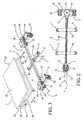
- Each trailer 3 comprises an associated rolling frame 4, in the example illustrated in FIG. figure 1 , to two bearing structures 8 adapted to transport small loads in the form of containers, pallets, crates or the like, small in size and limited weight.
- Each rolling frame 4 comprises rolling means 5 capable of following a precise trajectory and coupling means 6 capable of coupling the trailers 3 to each other and to the towing vehicle 2. It also comprises coupling means 7 capable of coupling at least one supporting structure 8 to the rolling frame 4 and in a removable manner.
- the bearing structure 8 also comprises own bearing means 9 allowing it to be displaced with respect to the rolling frame 4.
- the rolling means 5 of each rolling frame 4 comprises two axles 50, 51, one carrying a wheel 52 and the other two wheels 52 parallel, interconnected by a spar 40. These wheels 52 are fixed wheels.
- the two axles 50, 51 are mounted at the ends of the spar 40 so as to be rotatable about their central axis A, B and are directly coupled to the coupling means 6. They are also coupled together by means of a mechanical transmission arranged to turn them in the opposite direction, by any suitable means.
- this mechanical transmission consists of a cable 53 arranged in a closed loop crossed around two pulleys 54 each secured to an axle 50, 51 (cf. Fig. 2 ).
- This cable 53 may be metallic and its ends 55 may be fixed to one of the axles 51 by adjustment means (not shown) in the form of a screw system or the like making it possible to adjust the parallelism between the two axles 50, 51.
- adjustment means not shown
- the axle 50 is pivoted about its axis of rotation A of the same angle, pulling on the cable 53 in the same direction of rotation.
- the traction exerted on the cable 53 by the pulley 54 is transmitted to the other pulley 54 but in an inverted direction of rotation, the two strands of the cable 53 crossing under the spar 40.
- the axle 51 is consequently pivoted in direction inverted the same angle as the drawbar 60.
- the coupling means 6 comprise, in the illustrated example, a side of the rolling frame 4, integral with the axle 50, a drawbar 60 terminated by an eyelet 61 and, on the other side of the rolling frame 4, a pivot 62 integral and coincident with the axis of rotation B of the axle 51, adapted to engage in the eyelet 61 of the drawbar 60 of the following rolling frame 4.
- other equivalent coupling means may be suitable such as a ball joint, an elastic connection or the like.
- the spar 40 has a rectilinear shape and is aligned with the axes of rotation A, B of the two axles 50, 51. It can be achieved by means of a profile or a folded metal sheet or the like and integrally carries the coupling means 7 for receiving the bearing structure or structures 8.
- These coupling means 7 comprise two crosspieces 70 arranged perpendicularly and crosswise with respect to the spar 40, at predefined positions as a function of the size of the supporting structures 8 to tow.
- the bearing structures 8 comprise in correspondence of these cross members 70, a transverse housing 80 slidable on the cross members 70 thus forming guide rails. The displacement of the bearing structures 8 perpendicular to the rolling frame 4 is symbolized by the arrow D.
- the cross members 70 comprise a running surface formed by rollers 71 mounted at the ends and at the center of the cross members 70, free to rotate around of their axis.
- These coupling means 7 also comprise locking means to prevent the exit of the bearing structure 8 when it is coupled to the rolling frame 4.
- These locking means comprise a locking pin 72 mounted on each cross member 70 and arranged to cooperate with a recess (not shown) formed in the bearing structure 8. This locking pin 72 is coupled on the one hand to a return member (not shown) adapted to urge it into the locked position, and on the other hand to a locking member.
- maneuver 73 such as a pedal accessible by the foot of the operator and arranged to control its unlocked position.
- the cross position of the cross members 70 on the spar 40 allows to create two inputs, on either side of the chassis 4, to receive the bearing structures 8 independently of one side or the other, which allows a great flexibility of use. This is the reason why the construction of the cross members 70 is symmetrical with respect to the spar 40.
- the bearing structure 8 as represented in the figure 1 has a substantially parallelepipedal shape and consists of a lower plate 81 and an upper plate 82 parallel to each other and connected by a rear wall 83 and a longitudinal reinforcement 84, defining a lateral opening.
- the lower plate 81 carries the own bearing means 9 formed of four idler rollers 90 and has the transverse housing 80 slidable on the cross members 70 of the rolling frame 4.
- One of the wheels 90 can be coupled to a locking mechanism to make it director especially when the bearing structure 8 is no longer coupled to the rolling frame 4, in order to facilitate its handling.
- the upper plate 82 forms a platform for receiving the load in the form for example of a container, a pallet, a box, or the like.
- This bearing structure 8 is for example made of folded metal sheets and welded or riveted. It can of course be achieved by any other equivalent means such as profile frames, wire mesh panels, a wooden platform or the like. It can also be equipped with retaining means capable of securing the transported load, for example hoops and / or rear and / or side walls, a front locking bar, as well as gripping means capable of facilitating the manual movement of the load bearing structure 8 empty and / or loaded, for example a bow or a front bar with a handle. These examples are not limiting.
- the figure 3 illustrates a trailer 3 'slightly different from the previous one.
- the rolling chassis 4 ' also represented alone at the figure 4 , is carried by four wheels Instead of three, the axle 50 'being equivalent to the axle 51 and carrying two wheels 52.
- the coupling means 7 comprises only a cross member 70 disposed substantially at the center of the spar 40' to receive a only bearing structure 8 'larger than the bearing structures 8 for transporting larger loads or requiring a larger platform.
- the other components, which remain the same, have the same references and are not re-described.
- the figure 5 illustrates another type of rolling frame 4 "which differs from the previous ones in that the spar 40" has a C shape, the large branch of C being offset relative to the axes of rotation A, B of the axles 50 ', 51, delimiting a single entry to receive a single supporting structure 8 '.
- the coupling means 7 comprises a cross member 70 'disposed substantially in the center of the large branch of C, having a greater width than the previous cross members 70 and having eight rollers 71 distributed peripherally to form the rolling surface necessary for sliding. of a bearing structure 8 '.
- the mechanical transmission cable 53 and pulleys 54 comprises diverting pulleys 54 'arranged in the corners of the branches of C to guide the cable 53 so that it follows a path substantially coincident with the C shape of the spar 40 ".
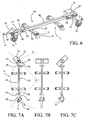
- the figure 6 illustrates a rolling chassis 4a whose construction is equivalent to that of the rolling chassis 4 of figures 1 and 2 , the same components bearing the same references.
- the difference lies in the mechanical transmission constituted by a set of rods 56-58 replacing cable 53 and pulleys 54.
- the Figures 7A to 7C illustrate the operation of this mechanical transmission, the rolling frame 4a being shown in plan views respectively in the left turn position, in a straight line and right turn.
- a central rod 56 extending in the axis of the spar 40 over almost its entire length and whose ends are each coupled to the axles 50, 51 by means of two other rods 57, 58 hinged: a transverse rod 58 connected in its center at the central link 56 and articulated at one of its ends around a fixed point 59 of the spar 40 and at the other end to an off-center rod 57 hinged about a fixed point of the axle 50, 51 corresponding, offset relative to the axis of rotation A, B.
- a transverse rod 58 connected in its center at the central link 56 and articulated at one of its ends around a fixed point 59 of the spar 40 and at the other end to an off-center rod 57 hinged about a fixed point of the axle 50, 51 corresponding, offset relative to the axis of rotation A, B.
- This mechanical transmission rods can of course be transposed to other variants of the rolling chassis 4'a and 4 "in accordance with Figures 8 and 9 and whose mechanical construction is similar to that of the rolling chassis 4 'and 4 "of Figures 4 and 5 , the same components bearing the same references.
- the rolling chassis 4 "has the figure 9 the set of rods is different because it must substantially follow the path of the spar 40 "C-shaped.
- the central link 56 is provided in or under the large branch of C and off-center rods 57 are substantially parallel to it and the same side.They are respectively connected by a right rod 58 'articulated with two L-shaped rods 58 ", each pivoting about a fixed point 59' of the spar 40".
- the conveyor train 1b of the figure 10 differs from that of the figure 1 in that it is particularly suitable for transporting heavy loads, for example greater than 300 kg.
- the trailers 3b are hitched together and to a vehicle 2.
- Each trailer 3b includes, also with reference to the figure 11 , a rolling chassis 4b and a bearing structure 8b.
- the undercarriage 4b comprises two axles 50, 51 hinged about their central axes A and B, the front axle 50 being provided with a wheel 52 and the rear axle 51 with one or two wheels 52.
- These axles 50, 51 are connected by a C-shaped spar 40b supported by a wheel 41 disposed substantially in the middle.
- the axles 50, 51 comprise, as in the previous examples, coupling means 6, constituted for example by a drawbar 60 and a pivot 62, and are controlled in the opposite direction by a mechanical transmission (not shown) with cables or with links passing under the spar 40b.
- the bearing structure 8b comprises a plate 85 supported by two fixed wheels 91 of coinciding axis, provided in the central part, and by at least two raised idler wheels 92 arranged at the front and rear of the plate 85.
- the arrangement fixed wheels 91 facilitates the introduction and release of the bearing structure 8b in the rolling frame 4b, by pivoting on itself effortlessly regardless of the load transported.
- the idler wheels 92 are doubled and are raised relative to the fixed wheels 91. They allow to balance the bearing structure 8b regardless of the load transported. These idler wheels 92 are offset from the edges of the plate 85 so as not to conflict with the spar 40b.
- the bearing structure 8b also comprises a gripping member 86 consisting of a handle provided at the front of the plate 85 to facilitate its handling.
- the coupling means 7 between the rolling frame 4b and the supporting structure 8b comprise a locking device 74.
- This locking device 74 comprises an articulated lever 75 provided at the front of the frame 4b and provided with an eyelet 76 intended to fit on a pin 77 provided at the front of the bearing structure 8b.
- This lever 75 cooperates with a spring device for locking its open position as illustrated in FIG. figure 11 and its closed position as illustrated in figure 10 .
- the C-shaped spar 40b allows the entry and exit of the bearing structure 8b of the same side.
- the bearing structure 8b of the rolling frame 4b is approached until the locking device 74 can be locked.
- the conveying train 1b is started up, the bearing structure 8b is positioned itself inside the spar 40b.
- the locking device 74 is unlocked and the supporting structure 8b is pivoted on itself by operating it by means of its handle 86.
- the plate 85 is designed to pass over the spar 40b during this maneuver.
- the spar may be arranged above the structure 8b, enabling it to be moved on one side and pulled out on the other side, the coupling being done with the same locking device 74.
- the spar can have a vertical C shape aligned with the axes of rotation A and B of the axles so as to define a so-called through entry.
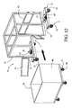
- the figure 12 illustrates another example of trailer 3c in which the rolling frame 4c can enter the bearing structure 8c on one side and out the other side. It is said that it defines a through entry.
- the rolling frame 4c comprises a cage 42 whose base and the lateral sides are open. Doors 43 with one or two leaves are provided on the lateral sides to control access to the cage 42 and guide the supporting structure 8c.
- the doors 43 as well as the front and rear walls of the cage 42 form the coupling means 7.
- the chassis 4c comprises two axles 50 ', 51 rotatably mounted about their central axis A, B and each carrying two wheels 52.
- the bearing structure 8c comprises a container 88 carried by four idler wheels 90, but may be constituted by any other type of load-bearing structures.
- a tractor 2 of known type is towed to a number of rolling frames 4 depending on the number of loads to be transported in one trip. This number is not limited and the choice of the rolling frame 4 depends on the supporting structures 8 to convey, which can be small or large.
- the coupling operation is carried out simply by inserting the eyelet 61 of the drawbar 60 of a rolling frame 4 on the attachment of the towing vehicle 2 or on a pivot 62 of the rolling chassis 4 above. This coupling is secured by means for example of a nut if the pivot 62 is threaded or by any other equivalent means.
- the conveyor train 1 is ready to circulate.
- the bearing structures 8 can be searched in a storage area, for example on which are stored parts in containers that must be delivered to workstations of a manufacturing plant for example.
- Each bearing structure 8 can be easily moved manually by the operator by pushing on the container or on a handle provided for this purpose to bring it in parallel with a rolling frame 4, its transverse opening 80 being positioned opposite the cross member 70 corresponding independently of one side or the other of the rolling frame 4.
- the supporting structure 8 is pushed onto the rolling frame 4, the transverse opening 80 rolling on the rollers 71 of the cross member 70.
- the locking pin 72 is retracted into position unlocked by the lower plate 81 of the supporting structure 8 until it faces the notch in which it locks automatically, binding the supporting structure 8 to the rolling frame 4 integrally.
- the operator can start his towing vehicle 2 and move with his conveyor train 1 in the aisles of the factory to deliver the parts to different workstations. For this purpose, it stops the conveyor train 1 at the desired locations, moves against the load to be delivered and presses with his foot on the pedal 73 to retract the locking finger 72 and release the desired bearing structure 8. It releases it from the rolling frame 4 by sliding it on the cross member 70 and then moves it to the corresponding workstation. It can do the same for other bearing structures 8 full and parallel it can load other bearing structures 8 which are empty, independently of one side or the other of the conveyor train 1. As explained above, the means of bearing 5 of the rolling chassis 4 allow to follow a trajectory with precision, without offset, the wheels 52 following a single trace.
- This transport system allows you to deliver and take back loads very easily, quickly, without wasting time, in any order and safely, which has the effect of improving and easing the flow of charges, to win time and work in masked time.
- the trailers 3 can be declined in different variants, as illustrated, to provide a solution adapted to each case.
Abstract
Description
La présente invention concerne une remorque pour train de convoyage de charges, cette remorque comportant un châssis roulant associé à au moins une structure portante destinée à transporter une charge, ledit châssis roulant comportant des moyens de roulement, des moyens d'attelage destinés à atteler ladite remorque à au moins une autre remorque ou à un véhicule tracteur dudit train de convoyage et des moyens de couplage agencés pour coupler ladite structure portante de manière amovible audit châssis roulant, cette structure portante comportant également des moyens de roulement propres de manière à pouvoir être déplacée par rapport audit châssis roulant.The present invention relates to a trailer for a load conveying train, this trailer comprising a rolling frame associated with at least one supporting structure intended to transport a load, said rolling frame comprising rolling means, coupling means for coupling said trailer to at least one other trailer or to a towing vehicle of said conveying train and coupling means arranged to couple said supporting structure removably to said rolling frame, this supporting structure also comprising own rolling means so as to be displaceable compared to said rolling chassis.
La présente invention concerne également un train de convoyage comportant au moins un véhicule tracteur et une série de remorques attelées.The present invention also relates to a conveyor train comprising at least one towing vehicle and a series of hitched trailers.
Le train de convoyage concerné par la présente invention est utilisé dans des zones de convoyage où l'approvisionnement et/ou le transit de charges est nécessaire comme par exemple dans les aéroports et/ou les gares pour assurer le transport des bagages et/ou de toute autre charge en transit, dans les usines de fabrication, de
transformation, de lignes de production pour assurer l'approvisionnement des postes de travail en matières premières, pièces et composants ainsi que l'évacuation des pièces ou sous-ensembles fabriqués et/ou assemblés vers d'autres postes de travail, etc. Ce type de train de convoyage permet de transporter les charges nues ou conditionnées en caisse, en container, sur palette ou sous toute autre forme équivalente, entre plusieurs zones, qui peuvent être des zones de déchargement, de stockage, de fabrication, de montage, d'assemblage, de chargement, etc. Le train de
convoyage peut suivre ou non une piste prédéfinie et peut circuler sur une trajectoire en boucle fermée le ramenant par exemple à son point de départ. Il peut également être programmé pour effectuer des parcours type et/ou être muni de capteurs de présence pour circuler en mode automatique et éviter les obstacles.The conveying train concerned by the present invention is used in conveying zones where the supply and / or the transit of loads is necessary, for example in airports and / or railway stations for the transport of luggage and / or any other load in transit, in the manufacturing plants, from
transformation of production lines to ensure the supply of workstations with raw materials, parts and components as well as the evacuation of parts or subassemblies manufactured and / or assembled to other workstations, etc. This type of conveying train makes it possible to transport the naked loads or packaged in the box, container, pallet or in any other equivalent form, between several zones, which can be unloading zones, storage, manufacturing, assembly, assembly, loading, etc. The train
conveying may or may not follow a predefined track and may travel on a closed-loop trajectory bringing it back, for example, to its starting point. It can also be programmed to carry out typical routes and / or be equipped with presence sensors to circulate in automatic mode and avoid obstacles.
Les charges transportées n'ont pas nécessairement la même destination et sont
habituellement chargées et déchargées des remorques au moyen d'engins de manutention tels que des chariots élévateurs. Ceci impose la mise à disposition permanente d'un ou de plusieurs caristes dont la fonction est de livrer la charge à l'endroit voulu. Pour limiter la manutention des charges et simplifier la logistique, certaines remorques peuvent être dételées, ce qui permet de livrer directement la charge avec sa remorque à l'endroit voulu et ainsi d'économiser le déplacement d'un engin de manutention. Néanmoins, le fait de dételer la remorque demande un temps d'intervention relativement long et fastidieux qui génère des temps d'arrêt importants du train de convoyage. Pour permettre au train de convoyage de poursuivre son chemin, les remorques restantes doivent être ré-attelées. Cette intervention impose au
conducteur du train de convoyage d'effectuer des manoeuvres et demande également une intervention longue et fastidieuse.Transported loads do not necessarily have the same destination and are
usually loaded and unloaded trailers using handling equipment such as forklifts. This requires the permanent provision of one or more operators whose function is to deliver the load to the desired location. To limit load handling and simplify logistics, some trailers can be unhitched, allowing the load to be delivered directly to the trailer with the trailer at the desired location, thus saving the expense of moving a material handling machine. Nevertheless, unhitching the trailer requires a relatively long and tedious intervention time that generates significant downtime of the conveyor train. To allow the ferry train to continue its journey, the remaining trailers must be re-hitched. This intervention requires
driver of the conveyor train to perform maneuvers and also requires a long and tedious intervention.
Certaines solutions ont été imaginées pour essayer de résoudre une partie des inconvénients mentionnés ci-dessus. Notamment, la publication
La publication
La
La
Le but de la présente invention est de résoudre les inconvénients ci-dessus en proposant une remorque pour train de convoyage qui soit simple, économique et très flexible, pouvant livrer rapidement les charges à l'endroit voulu, sans avoir besoin de dételer la remorque, avec un minimum d'efforts et un temps d'arrêt relativement court pour le train de convoyage de manière à simplifier considérablement la logistique et offrir une plus grande souplesse d'organisation dans le convoyage des charges d'un endroit à un autre, tout en réduisant l'investissement en matériels de manutention. Le but est également de proposer un train de convoyage pouvant comporter un nombre de remorques non limité et suivre les traces d'une trajectoire donnée, même étroite, sans couper les virages et sans déport des dernières remorques.The object of the present invention is to overcome the above disadvantages by providing a trailer for a conveyor train that is simple, economical and very flexible, can quickly deliver the loads to the desired location, without the need to unhitch the trailer, with minimal effort and a relatively short downtime for the conveyor train in order to simplify logistics considerably and offer greater flexibility in the organization of loads from one place to another, while reducing the investment in handling equipment. The goal is also to propose a conveyor train that can include a number of unrestrained trailers and follow the tracks of a given trajectory, even narrow, without cutting corners and without removing the last trailers.
Dans ce but, l'invention concerne une remorque telle que définie en préambule et caractérisée en ce que les moyens de roulement du châssis roulant comportent au moins trois roues réparties en deux essieux reliés entre eux par au moins un longeron, les moyens d'attelage étant couplés aux essieux et le longeron comportant les moyens de couplage, et en ce que les deux essieux sont montés mobiles en rotation autour de leur axe central par rapport audit longeron et sont couplés entre eux par une transmission mécanique agencée pour les faire tourner en sens inverse.For this purpose, the invention relates to a trailer as defined in the preamble and characterized in that the rolling frame rolling means comprise at least three wheels distributed in two axles interconnected by at least one spar, the coupling means being coupled to the axles and the spar having the coupling means, and in that the two axles are rotatably mounted about their central axis with respect to said spar and are coupled together by a mechanical transmission arranged to rotate them in direction reverse.
Dans ce but, l'invention concerne également un train de convoyage tel que défini en préambule, caractérisé en ce qu'il comporte des remorques telles que définies ci-dessus, les châssis roulants étant agencés pour rester attelés et les structures portantes étant agencées pour être couplées aux châssis roulants de manière amovible.For this purpose, the invention also relates to a conveyor train as defined in the preamble, characterized in that it comprises trailers as defined above, the rolling chassis being arranged to remain coupled and the supporting structures being arranged to be coupled to the rolling chassis removably.
La présente invention et ses avantages apparaîtront mieux dans la description suivante de plusieurs modes de réalisation donnés à titre d'exemple non limitatif, en référence aux dessins annexés, dans lesquels :
- la
figure 1 représente un exemple de train de convoyage selon l'invention, formé de trois châssis roulants attelés, dont un châssis roulant tracte deux petites structures portantes côte à côte, - la
figure 2 est une vue de dessous du châssis roulant à câbles, du train de lafigure 1 , - la
figure 3 est une vue en perspective d'une remorque selon une première variante de réalisation, le châssis roulant à câbles étant agencé pour recevoir une grande structure portante, - les
figures 4 et 5 sont des vues en perspective d'un châssis roulant à câbles selon une deuxième et une troisième variantes de réalisation, - la
figure 6 est une vue en perspective d'un châssis roulant à biellettes dont la structure est sensiblement similaire à celle desfigures 1 et2 , - les
figures 7A, 7B et 7C sont des vues de dessus du châssis roulant de lafigure 6 respectivement en virage à gauche, en ligne droite et en virage à droite, - les
figures 8 et 9 sont des vues en perspective d'un châssis roulant à biellettes selon une deuxième et une troisième variantes de réalisation dont la structure est sensiblement similaire à celle desfigures 4 et 5 , - la
figure 10 est une vue d'un autre train de convoyage selon l'invention, - la
figure 11 est une vue en perspective d'une remorque du train de convoyage de lafigure 10 , et - la
figure 12 est une autre variante de remorque selon l'invention.
- the
figure 1 represents an example of a conveying train according to the invention, consisting of three coupled rolling frames, of which a rolling frame pulls two small supporting structures side by side, - the
figure 2 is a bottom view of the rolling chassis with cables, the train of thefigure 1 , - the
figure 3 is a perspective view of a trailer according to a first embodiment, the rolling chassis with cables being arranged to receive a large supporting structure, - the
Figures 4 and 5 are perspective views of a rolling chassis with cables according to a second and a third variant embodiment, - the
figure 6 is a perspective view of a link rolling frame whose structure is substantially similar to that offigures 1 and2 , - the
Figures 7A, 7B and 7C are top views of the rolling chassis of thefigure 6 respectively in a left turn, a straight line and a right turn, - the
Figures 8 and 9 are perspective views of a link roller chassis according to a second and a third embodiment whose structure is substantially similar to that ofFigures 4 and 5 , - the
figure 10 is a view of another conveyor train according to the invention, - the
figure 11 is a perspective view of a trailer of the ferry train of thefigure 10 , and - the
figure 12 is another variant of the trailer according to the invention.
En référence aux
Chaque remorque 3 comporte un châssis roulant 4 associé, dans l'exemple illustré à la
En référence également aux
ou à droite, entraîné par le véhicule tracteur 2 ou le châssis roulant 4 précédent, l'essieu 50 est pivoté autour de son axe de rotation A du même angle, tirant sur le câble 53 dans le même sens de rotation. La traction exercée sur le câble 53 par la poulie 54 se transmet à l'autre poulie 54 mais dans un sens de rotation inversé, les deux brins du câble 53 se croisant sous le longeron 40. L'essieu 51 est par conséquent pivoté en sens inversé du même angle que le timon 60. Les axes des roues 52 sont alors concourants en un point correspondant au centre du virage. Ces moyens de roulement 5 ont donc l'avantage de permettre aux roues 52 des châssis roulants 4 formant le train de convoyage 1 de suivre la même trajectoire, appelée mono trace, même lors de virages serrés.With reference also to
or on the right, driven by the towing
Les moyens d'attelage 6 comportent, dans l'exemple illustré, d'un côté du châssis roulant 4, solidaire de l'essieu 50, un timon 60 terminé par un oeillet 61 et, de l'autre côté du châssis roulant 4, un pivot 62 solidaire et confondu avec l'axe de rotation B de l'essieu 51, apte à s'engager dans l' oeillet 61 du timon 60 du châssis roulant 4 suivant. Bien entendu, d'autres moyens d'attelage équivalents peuvent convenir comme par exemple une liaison à rotule, une liaison élastique ou similaire.The coupling means 6 comprise, in the illustrated example, a side of the rolling
Dans l'exemple illustré, le longeron 40 a une forme rectiligne et est aligné avec les axes de rotation A, B des deux essieux 50, 51. Il peut être réalisé au moyen d'un profilé ou d'une tôle pliée métallique ou similaire et porte solidairement les moyens de couplage 7 permettant de recevoir la ou les structures portantes 8. Ces moyens de couplage 7 comportent deux traverses 70 disposées perpendiculairement et en croix par rapport au longeron 40, à des positions prédéfinies en fonction de la dimension des structures portantes 8 à tracter. Les structures portantes 8 comportent en correspondance de ces traverses 70, un logement transversal 80 apte à coulisser sur les traverses 70 formant ainsi des rails de guidage. Le déplacement des structures portantes 8 perpendiculairement au châssis roulant 4 est symbolisé par la flèche D. Pour faciliter ce coulissement, les traverses 70 comportent une surface de roulement formée par des galets 71 montés aux extrémités et au centre des traverses 70, libres en rotation autour de leur axe. Ces moyens de couplage 7 comportent également des moyens de verrouillage pour empêcher la sortie de la structure portante 8 lorsqu'elle est couplée au châssis roulant 4. Ces moyens de verrouillage comportent un doigt de verrouillage 72 monté sur chaque traverse 70 et agencé pour coopérer avec un évidement (non représenté) ménagé dans la structure portante 8. Ce doigt de verrouillage 72 est couplé d'une part à un organe de rappel (non représenté) apte à le solliciter en position verrouillée, et d'autre part à un organe de manoeuvre 73 tel qu'une pédale accessible par le pied de l'opérateur et agencé pour commander sa position déverrouillée. La position en croix des traverses 70 sur le longeron 40
permet de créer deux entrées, de part et d'autre du châssis roulant 4, pour recevoir les
structures portantes 8 indépendamment d'un côté ou de l'autre, ce qui permet une
grande souplesse d'utilisation. C'est la raison pour laquelle la construction des traverses 70 est symétrique par rapport au longeron 40.In the example shown, the
allows to create two inputs, on either side of the
bearing
great flexibility of use. This is the reason why the construction of the
La structure portante 8 telle que représentée dans la
La
La
La
Cette transmission mécanique à biellettes peut bien entendu être transposée aux autres variantes de réalisation du châssis roulant 4'a et 4"a conformément aux
Le train de convoyage 1b de la
La structure portante 8b comporte un plateau 85 supporté par deux roues fixes 91 d'axe confondu, prévues dans la partie centrale, et par au moins deux roues folles 92 surélevées disposées à l'avant et à l'arrière du plateau 85. La disposition des roues fixes 91 facilite l'introduction et le dégagement de la structure portante 8b dans le châssis roulant 4b, en la faisant pivoter sur elle-même sans effort quelle que soit la charge transportée. Dans l'exemple représenté, les roues folles 92 sont doublées et sont surélevées par rapport aux roues fixes 91. Elles permettent d'équilibrer la structure portante 8b quelle que soit la charge transportée. Ces roues folles 92 sont décalées des bords du plateau 85 pour ne pas entrer en conflit avec le longeron 40b.
La structure portante 8b comporte également un organe de préhension 86 constitué d'une poignée prévue à l'avant du plateau 85 pour faciliter sa manutention.The bearing
The bearing
Dans cet exemple, les moyens de couplage 7 entre le châssis roulant 4b et la structure portante 8b comportent un dispositif de verrouillage 74. Ce dispositif de verrouillage 74 comporte un levier 75 articulé prévu à l'avant du châssis 4b et pourvu d'un oeillet 76 destiné à s'emboîter sur un téton 77 prévu à l'avant de la structure portante 8b. Ce levier 75 coopère avec un dispositif à ressort permettant de bloquer sa position ouverte telle qu'illustrée à la
La forme en C du longeron 40b permet l'entrée et la sortie de la structure portante 8b du même côté. Lorsque l'on souhaite transporter une charge, on approche la structure portante 8b du châssis roulant 4b jusqu'à pouvoir verrouiller le dispositif de verrouillage 74. Lors de la mise en marche du train de convoyage 1b, la structure portante 8b se positionne d'elle-même à l'intérieur du longeron 40b. Pour ressortir la charge, on déverrouille le dispositif de verrouillage 74 et on pivote la structure portante 8b sur elle-même en la manoeuvrant par sa poignée 86. Le plateau 85 est conçu pour passer au-dessus du longeron 40b pendant cette manoeuvre.The C-shaped
En variante, le longeron peut être disposé au-dessus de la structure 8b, permettant de la rentrer d'un coté et de la sortir de l'autre coté, le couplage se faisant avec le même dispositif de verrouillage 74. Dans cette variante (non représentée), le longeron peut avoir une forme en C vertical aligné avec les axes de rotation A et B des essieux de manière à définir une entrée dite traversante.As a variant, the spar may be arranged above the
La
Le fonctionnement du train de convoyage 1 selon l'invention est décrit ci-après en référence au mode de réalisation de la
ou de l'autre du châssis roulant 4. On pousse la structure portante 8 sur le châssis roulant 4, l'ouverture transversale 80 roulant sur les galets 71 de la traverse 70. Pendant la manoeuvre, le doigt de verrouillage 72 est escamoté en position déverrouillée par le plateau inférieur 81 de la structure portante 8 jusqu'à ce qu'il soit face à l'encoche dans laquelle il se verrouille automatiquement, liant solidairement la structure portante 8 au châssis roulant 4. Lorsque le chargement du train de convoyage 1 est terminé, l'opérateur peut démarrer son véhicule tracteur 2 et circuler avec son train de convoyage 1 dans les allées de l'usine pour livrer les pièces aux différents postes de travail. A cet effet, il arrête le train de convoyage 1 aux endroits souhaités, se déplace face à la charge à livrer et appuie avec son pied sur la pédale 73 pour escamoter le doigt de verrouillage 72 et libérer la structure portante 8 voulue. Il la dégage du châssis roulant 4 en la faisant coulisser sur la traverse 70 puis la déplace jusqu'au poste de travail correspondant. Il peut faire de même pour les autres structures portantes 8 pleines et parallèlement il peut charger d'autres structures portantes 8 qui sont vides, indépendamment d'un côté ou de l'autre du train de convoyage 1. Comme expliqué précédemment, les moyens de roulement 5 des châssis roulants 4 permettent de suivre une trajectoire avec précision, sans déport, les roues 52 suivant une mono trace. Ce système de transport permet de livrer et de reprendre des charges très facilement, rapidement, sans perte de temps, dans un ordre quelconque et en toute sécurité, ce qui a pour effet d'améliorer et d'assouplir le flux des charges, de gagner du temps et de travailler en temps masqué. De plus, les remorques 3 peuvent être déclinées en différentes variantes, comme illustrées, permettant d'offrir une solution adaptée à chaque cas de figure.The operation of the conveyor train 1 according to the invention is described below with reference to the embodiment of the
or the other of the rolling
La présente invention n'est pas limitée aux exemples de réalisation décrits mais s'étend à toute modification et variante évidentes pour un homme du métier tout en restant dans l'étendue de la protection définie dans les revendications annexées.The present invention is not limited to the embodiments described but extends to any modification and variation obvious to a person skilled in the art while remaining within the scope of protection defined in the appended claims.
Claims (21)
- A trailer (3, 3', 3b, 3c) for a transport train (1, 1b) for loads, this trailer (3, 3', 3b, 3c) comprising a rolling chassis (4, 4', 4", 4a, 4'a, 4"a, 4b, 4c) associated with at least one load-bearing structure (8, 8', 8b, 8c) intended to transport a load, the said rolling chassis comprising rolling means (5), hitching means (6) intended to hitch the said trailer removably to at least one other trailer or to a towing vehicle (2) of the said transport train (1) and coupling means (7) designed to couple the said load-bearing structure removably to the said rolling chassis, this load-bearing structure (8, 8', 8b, 8c) also comprising rolling means (9) suitable to be able to be displaced in relation to the said rolling chassis, characterised in that the rolling means (5) of the said rolling chassis (4, 4', 4", 4a, 4'a, 4"a, 4b, 4c) comprise at least three wheels (52) distributed over two axles (50, 50', 51) connected to each other by a longitudinal chassis beam (40, 40', 40", 40b, 42), the said hitching means (6) being coupled to the said axles (50, 50', 51) and the said longitudinal chassis beam comprising the said coupling means, and in that the two axles (50, 50', 51) are mounted to rotate about their central axis (A, B) in relation to the said longitudinal beam and are coupled to each other by a mechanical transmission designed to make them turn in the opposite direction.
- A trailer according to Claim 1, characterised in that the rolling chassis (4', 4", 4'a, 4"a) is borne by four wheels (52), two wheels (52) for each axle (50', 51).
- A trailer according to Claim 1, characterised in that the mechanical transmission comprises at least one pulley (54) on each axle (50, 50', 51) and at least one cable (53) connecting the two pulleys (54, 54') as a crosswise closed loop.
- A trailer according to Claim 1, characterised in that the mechanical transmission comprises a set of articulated connecting rods (56-58, 58', 58").
- A trailer according to one of Claims 3 or 4, characterised in that the mechanical transmission comprises regulating means designed to adjust the parallelism between the two axles (50, 50', 51).
- A trailer according to Claim 1, characterised in that the said longitudinal beam (40, 40') has a rectilinear shape, is aligned with the axes of rotation (A, B) of the axles (50, 50', 51) and is designed to define two openings disposed on either side of the said longitudinal beam to receive at least one load-bearing structure (8, 8').
- A trailer according to Claim 1, characterised in that the said longitudinal beam (40", 40b) is C-shaped, the large branch of the C being shifted in relation to the axes of rotation (A, B) of the said axles (50, 50', 51) and designed to define a single opening disposed on the open side of the longitudinal beam to receive at least one load-bearing structure (8, 8', 8b).
- A trailer according to one of Claims 6 or 7, characterised in that the coupling means (7) comprise at least one crossbeam (70, 70') disposed substantially perpendicularly to the said longitudinal beam (40, 40', 40") of the rolling chassis (4, 4', 4", 4a, 4'a, 4"a) and designed to receive by sliding at least one load-bearing structure (8, 8'), this structure comprising at last one transverse seat (80) having a section that is substantially complementary to that of the said crossbeam (70, 70').
- A trailer according to Claim 8, characterised in that the coupling means (7) comprise two crossbeams (70) disposed substantially parallel to each other, each crossbeam (70) being designed to receive a load-bearing structure (8).
- A trailer according to one of Claims 8 or 9, characterised in that at least the said crossbeam (70, 70') or the said transverse seat (80) comprises a rolling surface designed to guide the load-bearing structure (8, 8') in relation to the said rolling chassis (4, 4', 4", 4a, 4'a, 4"a).
- A trailer according to Claim 10, characterised in that the said crossbeam (70, 70') comprises at least one roller (71) disposed so as to form the said rolling surface.
- A trailer according to Claim 1, characterised in that the said longitudinal beam is C-shaped, is aligned with the axes of rotation (A, B) of the said axles and is designed to define a cross opening to receive at least one load-bearing structure.
- A trailer according to Claim 1, characterised in that the said longitudinal beam comprises an open cage (42) designed to define a cross opening to receive at least one load-bearing structure (8c).
- A trailer according to any one of the preceding Claims, characterised in that the said coupling means (7) comprise locking means designed to prevent the said load-bearing structure (8, 8', 8b, 8c) coming out when it is coupled to the said rolling chassis (4, 4', 4", 4a, 4'a, 4"a, 4b, 4c).
- A trailer according to Claim 14, characterised in that the said locking means comprise at least one locking finger (72), provided on at least one crossbeam (70, 70') or on the said load-bearing structure (8, 8'), this locking finger moving between an unlocked position and a locked position and being coupled to at least one control mechanism (73) designed to control at least the unlocked position.
- A trailer according to Claim 14, characterised in that the said locking means comprise at least one articulated lever (75) provided at the front of the said rolling chassis (4b) or the said load-bearing structure (8b), this lever being provided with a eyelet (76) designed to fit onto a lug (77) provided at the front of the said load-bearing structure (8b) or the said rolling chassis (4b).
- A trailer according to Claim 1, characterised in that the hitching means (6) are chosen from the group comprising a pivot linkage (60-62), a ball linkage, and an elastic linkage.
- A trailer according to Claim 1, characterised in that the rolling means (9) of the said load-bearing structure (8, 8', 8c) comprise at least four loose rollers (90).
- A trailer according to Claim 18, characterised in that at least one roller (90) is coupled to a locking mechanism designed to make this a steering roller (90) when the bearing structure (8, 8', 8c) is uncoupled from the said rolling chassis.
- A trailer according to Claim 1, characterised in that the rolling means (9) of the said load-bearing structure (8b) comprise two fixed wheels (91) with a shared axle disposed in the central part and at least two elevated loose wheels (92) disposed at the front and at the rear.
- A transport train (1, 1b) comprising at least one towing vehicle (2) and a series of hitched trailers (3, 3', 3b, 3c) according to one of the preceding Claims, the said rolling chassis (4, 4', 4", 4a, 4'a, 4"a, 4b, 4c) being designed to remain hitched and the said load-bearing structures (8, 8', 8b, 8c) being designed to be movably coupled to the said rolling chassis.
Applications Claiming Priority (1)
| Application Number | Priority Date | Filing Date | Title |
|---|---|---|---|
| FR0507403A FR2888200B1 (en) | 2005-07-11 | 2005-07-11 | TRAILER FOR CONVEYING TRAIN AND CONVEYING TRAIN OBTAINED |
Publications (2)
| Publication Number | Publication Date |
|---|---|
| EP1743828A1 EP1743828A1 (en) | 2007-01-17 |
| EP1743828B1 true EP1743828B1 (en) | 2008-09-17 |
Family
ID=36001077
Family Applications (1)
| Application Number | Title | Priority Date | Filing Date |
|---|---|---|---|
| EP06360029A Active EP1743828B1 (en) | 2005-07-11 | 2006-07-07 | Trailer for a transport train and transport train thus obtained |
Country Status (5)
| Country | Link |
|---|---|
| EP (1) | EP1743828B1 (en) |
| AT (1) | ATE408551T1 (en) |
| DE (1) | DE602006002784D1 (en) |
| ES (1) | ES2314860T3 (en) |
| FR (1) | FR2888200B1 (en) |
Cited By (7)
| Publication number | Priority date | Publication date | Assignee | Title |
|---|---|---|---|---|
| DE102011106842A1 (en) | 2011-07-07 | 2013-01-10 | A & A Logistik-Equipment GmbH & Co. KG | Tugger train for transporting goods, has trailer connected with towing vehicle or another trailer using connector that comprises two connecting rods, where rods comprise vertical rotational axis and exhibits equal length |
| EP2660127A2 (en) | 2012-05-04 | 2013-11-06 | Neumaier Industry GmbH & Co. KG | Running gear unit and modular unit for a tugger train |
| EP2689984A1 (en) | 2012-07-24 | 2014-01-29 | Jungheinrich Aktiengesellschaft | Transport train with a tow vehicle and one or more trailers |
| DE102013014099A1 (en) * | 2013-08-23 | 2015-02-26 | Thomas Bühler | Dolly with chassis for a tugger train |
| DE102013112635A1 (en) | 2013-11-15 | 2015-05-21 | Jungheinrich Aktiengesellschaft | Tug with a towing vehicle and at least one towed trailer |
| DE102014004318A1 (en) | 2014-03-25 | 2015-10-01 | A&A Logistik-Equipment GmbH & Co. KG | tugger |
| EP3126190B1 (en) | 2014-03-31 | 2018-02-14 | LR Intralogistik GmbH | Trailer-train trailer having a carrying frame for a transport-material cart |
Families Citing this family (21)
| Publication number | Priority date | Publication date | Assignee | Title |
|---|---|---|---|---|
| EP2205474B1 (en) | 2007-09-21 | 2017-03-29 | Willibald Hergeth | Transport system, in particular having movable pallets |
| DE102008034938B4 (en) * | 2008-07-26 | 2012-05-16 | Hupfer Metallwerke Gmbh & Co. Kg | Centering device for a transport unit module |
| DE102008060962B4 (en) * | 2008-09-06 | 2021-10-21 | Bayerische Motoren Werke Aktiengesellschaft | Trailer trailer |
| DE102009050966B4 (en) * | 2009-10-28 | 2023-05-11 | Dr. Ing. H.C. F. Porsche Aktiengesellschaft | Picking trolley for transporting picking goods |
| FR2953479B1 (en) * | 2009-12-07 | 2012-05-11 | Ecomover | DEVICE FOR MOVING MOBILE CONTAINERS |
| FR2955290B1 (en) * | 2010-01-19 | 2015-05-01 | Ecomover | DEVICE FOR COUPLING A ROLLING CONTAINER |
| DE102011012407A1 (en) * | 2011-02-25 | 2012-08-30 | Still Gmbh | Trailer, tractor and tractor train formed therefrom |
| DE102011017346B4 (en) | 2011-04-16 | 2022-01-05 | Jungheinrich Aktiengesellschaft | Trailer for a pallet truck in a tugger train |
| FR2976893B1 (en) * | 2011-06-27 | 2020-09-25 | Coutier Ind | ROLLING BASE AND WORKSHOP CART |
| PL2540530T3 (en) | 2011-06-27 | 2018-04-30 | Coutier Industrie | Trailer train |
| EP2540531B1 (en) | 2011-06-27 | 2017-05-03 | Coutier Industrie | Trailer train |
| FR2986208B1 (en) * | 2012-02-01 | 2015-04-10 | Peugeot Citroen Automobiles Sa | TRAILER FOR CONVEYING TRAINS |
| DE102012104585A1 (en) * | 2012-05-29 | 2013-12-05 | Blickle Räder + Rollen GmbH & Co. KG | Transport trolley and a method for moving a trolley |
| DE102012017838A1 (en) | 2012-09-10 | 2014-03-13 | Beewatec Gmbh | Single-axle pull-pull element with lifting device and chassis for a single-axis pull-pull element |
| DE102013008242B4 (en) | 2013-05-15 | 2016-05-12 | Beewatec Gmbh | Traction pull with lifting device |
| ITPI20140091A1 (en) * | 2014-12-03 | 2016-06-03 | Movincar S P A | VEHICLE TO TRANSPORT PALLETIZED MATERIALS |
| DE102015225295A1 (en) * | 2015-12-15 | 2017-06-22 | Neumaier Industry Gmbh & Co. Kg | Tug-train module unit and tugger train |
| DE202016102994U1 (en) * | 2016-06-06 | 2016-08-03 | Lr Intralogistik Gmbh | Trailerzuganhänger |
| JP7070869B2 (en) * | 2018-03-30 | 2022-05-18 | 日本電産シンポ株式会社 | Automated guided vehicle |
| CN110371451B (en) * | 2019-07-16 | 2021-06-08 | 莱芜职业技术学院 | Commodity circulation is with concatenation goods shelves fast |
| RU2748087C1 (en) * | 2020-06-03 | 2021-05-19 | Александр Владимирович Новиков | Device for coupling a towing vehicle with a load and its automatic uncoupling |
Family Cites Families (7)
| Publication number | Priority date | Publication date | Assignee | Title |
|---|---|---|---|---|
| FR1273488A (en) * | 1960-08-31 | 1961-10-13 | A Devianne Duquesnoy Fils De | Improvements to the assembly of the wheels of industrial trucks |
| FR1363381A (en) * | 1963-05-02 | 1964-06-12 | Anciens Etablissements Grisier | Trailer truck |
| US3337234A (en) * | 1964-02-18 | 1967-08-22 | Kawasaki Rolling Stock Mfg Co | Steering arrangement for full trailers |
| NL8702291A (en) | 1987-09-25 | 1989-04-17 | Cooeperatieve Vereniging Veren | TRANSPORT CART. |
| US5906384A (en) | 1996-10-23 | 1999-05-25 | F/G Products, Inc. | Cart system for moving product |
| FR2838081B1 (en) | 2002-04-09 | 2004-09-03 | Plastic Omnium Cie | HEAT FLUID DISTRIBUTOR FOR A CHANNEL NETWORK OF A MOTOR VEHICLE RADIATOR AND TECHNICAL FRONT PANEL OBTAINED FROM SUCH A DISTRIBUTOR |
| FR2838398B1 (en) * | 2002-04-11 | 2004-12-24 | Fideves | TRAILER FOR CONVEYOR TRAIN |
-
2005
- 2005-07-11 FR FR0507403A patent/FR2888200B1/en not_active Expired - Fee Related
-
2006
- 2006-07-07 ES ES06360029T patent/ES2314860T3/en active Active
- 2006-07-07 AT AT06360029T patent/ATE408551T1/en not_active IP Right Cessation
- 2006-07-07 EP EP06360029A patent/EP1743828B1/en active Active
- 2006-07-07 DE DE602006002784T patent/DE602006002784D1/en active Active
Cited By (11)
| Publication number | Priority date | Publication date | Assignee | Title |
|---|---|---|---|---|
| DE102011106842A1 (en) | 2011-07-07 | 2013-01-10 | A & A Logistik-Equipment GmbH & Co. KG | Tugger train for transporting goods, has trailer connected with towing vehicle or another trailer using connector that comprises two connecting rods, where rods comprise vertical rotational axis and exhibits equal length |
| EP2660127A2 (en) | 2012-05-04 | 2013-11-06 | Neumaier Industry GmbH & Co. KG | Running gear unit and modular unit for a tugger train |
| DE102013200612A1 (en) | 2012-05-04 | 2013-11-07 | Neumaier Industry Gmbh & Co. Kg | Chassis unit and module unit for a tugger train |
| EP2689984A1 (en) | 2012-07-24 | 2014-01-29 | Jungheinrich Aktiengesellschaft | Transport train with a tow vehicle and one or more trailers |
| DE102012014607A1 (en) | 2012-07-24 | 2014-05-15 | Jungheinrich Aktiengesellschaft | Transport train with a towing vehicle and one or more trailers |
| DE102013014099A1 (en) * | 2013-08-23 | 2015-02-26 | Thomas Bühler | Dolly with chassis for a tugger train |
| DE102013014099B4 (en) * | 2013-08-23 | 2017-07-06 | Thomas Bühler | Dolly with chassis for a tugger train |
| DE102013112635A1 (en) | 2013-11-15 | 2015-05-21 | Jungheinrich Aktiengesellschaft | Tug with a towing vehicle and at least one towed trailer |
| EP2875971A1 (en) | 2013-11-15 | 2015-05-27 | Jungheinrich Aktiengesellschaft | Trailer train with a tractor and at least one towed trailer |
| DE102014004318A1 (en) | 2014-03-25 | 2015-10-01 | A&A Logistik-Equipment GmbH & Co. KG | tugger |
| EP3126190B1 (en) | 2014-03-31 | 2018-02-14 | LR Intralogistik GmbH | Trailer-train trailer having a carrying frame for a transport-material cart |
Also Published As
| Publication number | Publication date |
|---|---|
| ATE408551T1 (en) | 2008-10-15 |
| FR2888200B1 (en) | 2007-08-31 |
| FR2888200A1 (en) | 2007-01-12 |
| ES2314860T3 (en) | 2009-03-16 |
| DE602006002784D1 (en) | 2008-10-30 |
| EP1743828A1 (en) | 2007-01-17 |
Similar Documents
| Publication | Publication Date | Title |
|---|---|---|
| EP1743828B1 (en) | Trailer for a transport train and transport train thus obtained | |
| EP1352815B1 (en) | Trailer for transportation train | |
| WO2005100216A1 (en) | Installation and method for transferring a load between a transfer platform and a transport vehicle | |
| EP2540530B1 (en) | Trailer train | |
| EP3174757A1 (en) | Individual, universal, removable, load-bearing pallet for car-carrying vehicle | |
| EP2357117A1 (en) | Carriage device with two components | |
| FR2883242A1 (en) | Cargo carrying dolly type truck for e.g. household garbage container, has cargo-carrying structure moving between loading/unloading position to transport position, drawbar at hitch point, and additional drawbar to constitute cart train | |
| EP1918181A1 (en) | Tipping trailer equipped with a device for loading and unloading a load | |
| WO2008000999A2 (en) | Trolley comprising means for limiting the turning of the wheels | |
| FR2979609A1 (en) | Trailer for use in storage warehouse supermarket for transportation of trolleys, has lifting unit interposed between frame and rolling unit to lift frame from lowered position by rolling up to high position for transportation of trolleys | |
| EP3585631B1 (en) | Wheeled logistical module provided with a towing device | |
| FR2899196A1 (en) | TRACTOR FOR TRANSPORTING MOBILE TRANSPORT RECEPTACLES. | |
| FR3007695A1 (en) | MECHANICAL DEVICE FOR COUPLING DEBRAYABLE FROM A HANDLING TROLLEY TO AN AUTOGUID VEHICLE | |
| EP2303632B1 (en) | Handling-trucking device for a container or the like, and method for moving such devices in the absence of a container | |
| EP2246242B1 (en) | Trailer for an automobile comprising a retractable truck box | |
| FR3109756A1 (en) | Carriage carrier system | |
| EP2739506B1 (en) | Trolley for transporting loads and train consisting of such trolleys | |
| EP1285846B1 (en) | Trailer with lowerable platform , especially for agricultural machines | |
| EP0094280B1 (en) | Tipping trailer for carrying work sheds, mobile homes, platforms or the like | |
| EP3642124B1 (en) | Combination of a transport pallet for trolleys and one or more trolleys | |
| FR2833550A1 (en) | Hand operated transport trolley comprises container with rigid front fixed part with rear and lateral walls and bottom and transposable part movable between end positions having front and lateral walls and bottom | |
| FR3013637A1 (en) | COUPLING DEVICE FOR CONVEYOR TRAILER, CONVEYOR TRAILER PROVIDED WITH SUCH A COUPLING DEVICE AND CONVEYING TRAIN OBTAINED | |
| FR2920414A1 (en) | Wheeled trailer for collection of carton package, in e.g. supermarket, has interlocking units for interlocking trailer with another trailer, and including interlock opening co-operated with prehension unit during interlocking operation | |
| FR3072355A1 (en) | MOTORIZED TRANSPALETTE TROLLEY | |
| FR2828848A1 (en) | Trailer e.g. for agricultural material has wheels on sliding trolley that allows platform to be lowered for loading/unloading |
Legal Events
| Date | Code | Title | Description |
|---|---|---|---|
| PUAI | Public reference made under article 153(3) epc to a published international application that has entered the european phase |
Free format text: ORIGINAL CODE: 0009012 |
|
| AK | Designated contracting states |
Kind code of ref document: A1 Designated state(s): AT BE BG CH CY CZ DE DK EE ES FI FR GB GR HU IE IS IT LI LT LU LV MC NL PL PT RO SE SI SK TR |
|
| AX | Request for extension of the european patent |
Extension state: AL BA HR MK YU |
|
| 17P | Request for examination filed |
Effective date: 20070618 |
|
| AKX | Designation fees paid |
Designated state(s): AT BE BG CH CY CZ DE DK EE ES FI FR GB GR HU IE IS IT LI LT LU LV MC NL PL PT RO SE SI SK TR |
|
| GRAP | Despatch of communication of intention to grant a patent |
Free format text: ORIGINAL CODE: EPIDOSNIGR1 |
|
| GRAS | Grant fee paid |
Free format text: ORIGINAL CODE: EPIDOSNIGR3 |
|
| RAP1 | Party data changed (applicant data changed or rights of an application transferred) |
Owner name: MANULINE S.A.S. |
|
| GRAA | (expected) grant |
Free format text: ORIGINAL CODE: 0009210 |
|
| AK | Designated contracting states |
Kind code of ref document: B1 Designated state(s): AT BE BG CH CY CZ DE DK EE ES FI FR GB GR HU IE IS IT LI LT LU LV MC NL PL PT RO SE SI SK TR |
|
| REG | Reference to a national code |
Ref country code: GB Ref legal event code: FG4D Free format text: NOT ENGLISH |
|
| REG | Reference to a national code |
Ref country code: CH Ref legal event code: EP |
|
| REG | Reference to a national code |
Ref country code: IE Ref legal event code: FG4D Free format text: LANGUAGE OF EP DOCUMENT: FRENCH |
|
| REF | Corresponds to: |
Ref document number: 602006002784 Country of ref document: DE Date of ref document: 20081030 Kind code of ref document: P |
|
| REG | Reference to a national code |
Ref country code: SE Ref legal event code: TRGR |
|
| PG25 | Lapsed in a contracting state [announced via postgrant information from national office to epo] |
Ref country code: LT Free format text: LAPSE BECAUSE OF FAILURE TO SUBMIT A TRANSLATION OF THE DESCRIPTION OR TO PAY THE FEE WITHIN THE PRESCRIBED TIME-LIMIT Effective date: 20080917 |
|
| PG25 | Lapsed in a contracting state [announced via postgrant information from national office to epo] |
Ref country code: LV Free format text: LAPSE BECAUSE OF FAILURE TO SUBMIT A TRANSLATION OF THE DESCRIPTION OR TO PAY THE FEE WITHIN THE PRESCRIBED TIME-LIMIT Effective date: 20080917 Ref country code: SI Free format text: LAPSE BECAUSE OF FAILURE TO SUBMIT A TRANSLATION OF THE DESCRIPTION OR TO PAY THE FEE WITHIN THE PRESCRIBED TIME-LIMIT Effective date: 20080917 Ref country code: AT Free format text: LAPSE BECAUSE OF FAILURE TO SUBMIT A TRANSLATION OF THE DESCRIPTION OR TO PAY THE FEE WITHIN THE PRESCRIBED TIME-LIMIT Effective date: 20080917 Ref country code: FI Free format text: LAPSE BECAUSE OF FAILURE TO SUBMIT A TRANSLATION OF THE DESCRIPTION OR TO PAY THE FEE WITHIN THE PRESCRIBED TIME-LIMIT Effective date: 20080917 |
|
| REG | Reference to a national code |
Ref country code: ES Ref legal event code: FG2A Ref document number: 2314860 Country of ref document: ES Kind code of ref document: T3 |
|
| REG | Reference to a national code |
Ref country code: IE Ref legal event code: FD4D |
|
| PG25 | Lapsed in a contracting state [announced via postgrant information from national office to epo] |
Ref country code: BG Free format text: LAPSE BECAUSE OF FAILURE TO SUBMIT A TRANSLATION OF THE DESCRIPTION OR TO PAY THE FEE WITHIN THE PRESCRIBED TIME-LIMIT Effective date: 20081217 |
|
| PG25 | Lapsed in a contracting state [announced via postgrant information from national office to epo] |
Ref country code: PT Free format text: LAPSE BECAUSE OF FAILURE TO SUBMIT A TRANSLATION OF THE DESCRIPTION OR TO PAY THE FEE WITHIN THE PRESCRIBED TIME-LIMIT Effective date: 20090217 Ref country code: CZ Free format text: LAPSE BECAUSE OF FAILURE TO SUBMIT A TRANSLATION OF THE DESCRIPTION OR TO PAY THE FEE WITHIN THE PRESCRIBED TIME-LIMIT Effective date: 20080917 Ref country code: RO Free format text: LAPSE BECAUSE OF FAILURE TO SUBMIT A TRANSLATION OF THE DESCRIPTION OR TO PAY THE FEE WITHIN THE PRESCRIBED TIME-LIMIT Effective date: 20080917 Ref country code: IS Free format text: LAPSE BECAUSE OF FAILURE TO SUBMIT A TRANSLATION OF THE DESCRIPTION OR TO PAY THE FEE WITHIN THE PRESCRIBED TIME-LIMIT Effective date: 20090117 Ref country code: SK Free format text: LAPSE BECAUSE OF FAILURE TO SUBMIT A TRANSLATION OF THE DESCRIPTION OR TO PAY THE FEE WITHIN THE PRESCRIBED TIME-LIMIT Effective date: 20080917 |
|
| PLBE | No opposition filed within time limit |
Free format text: ORIGINAL CODE: 0009261 |
|
| STAA | Information on the status of an ep patent application or granted ep patent |
Free format text: STATUS: NO OPPOSITION FILED WITHIN TIME LIMIT |
|
| PG25 | Lapsed in a contracting state [announced via postgrant information from national office to epo] |
Ref country code: EE Free format text: LAPSE BECAUSE OF FAILURE TO SUBMIT A TRANSLATION OF THE DESCRIPTION OR TO PAY THE FEE WITHIN THE PRESCRIBED TIME-LIMIT Effective date: 20080917 Ref country code: DK Free format text: LAPSE BECAUSE OF FAILURE TO SUBMIT A TRANSLATION OF THE DESCRIPTION OR TO PAY THE FEE WITHIN THE PRESCRIBED TIME-LIMIT Effective date: 20080917 Ref country code: IE Free format text: LAPSE BECAUSE OF FAILURE TO SUBMIT A TRANSLATION OF THE DESCRIPTION OR TO PAY THE FEE WITHIN THE PRESCRIBED TIME-LIMIT Effective date: 20080917 |
|
| 26N | No opposition filed |
Effective date: 20090618 |
|
| PG25 | Lapsed in a contracting state [announced via postgrant information from national office to epo] |
Ref country code: MC Free format text: LAPSE BECAUSE OF NON-PAYMENT OF DUE FEES Effective date: 20090731 |
|
| PG25 | Lapsed in a contracting state [announced via postgrant information from national office to epo] |
Ref country code: PL Free format text: LAPSE BECAUSE OF FAILURE TO SUBMIT A TRANSLATION OF THE DESCRIPTION OR TO PAY THE FEE WITHIN THE PRESCRIBED TIME-LIMIT Effective date: 20080917 |
|
| PG25 | Lapsed in a contracting state [announced via postgrant information from national office to epo] |
Ref country code: GR Free format text: LAPSE BECAUSE OF FAILURE TO SUBMIT A TRANSLATION OF THE DESCRIPTION OR TO PAY THE FEE WITHIN THE PRESCRIBED TIME-LIMIT Effective date: 20081218 |
|
| REG | Reference to a national code |
Ref country code: CH Ref legal event code: PL |
|
| PG25 | Lapsed in a contracting state [announced via postgrant information from national office to epo] |
Ref country code: CH Free format text: LAPSE BECAUSE OF NON-PAYMENT OF DUE FEES Effective date: 20100731 Ref country code: LI Free format text: LAPSE BECAUSE OF NON-PAYMENT OF DUE FEES Effective date: 20100731 Ref country code: LU Free format text: LAPSE BECAUSE OF NON-PAYMENT OF DUE FEES Effective date: 20090707 |
|
| PG25 | Lapsed in a contracting state [announced via postgrant information from national office to epo] |
Ref country code: HU Free format text: LAPSE BECAUSE OF FAILURE TO SUBMIT A TRANSLATION OF THE DESCRIPTION OR TO PAY THE FEE WITHIN THE PRESCRIBED TIME-LIMIT Effective date: 20090318 |
|
| PG25 | Lapsed in a contracting state [announced via postgrant information from national office to epo] |
Ref country code: TR Free format text: LAPSE BECAUSE OF FAILURE TO SUBMIT A TRANSLATION OF THE DESCRIPTION OR TO PAY THE FEE WITHIN THE PRESCRIBED TIME-LIMIT Effective date: 20080917 |
|
| PG25 | Lapsed in a contracting state [announced via postgrant information from national office to epo] |
Ref country code: CY Free format text: LAPSE BECAUSE OF FAILURE TO SUBMIT A TRANSLATION OF THE DESCRIPTION OR TO PAY THE FEE WITHIN THE PRESCRIBED TIME-LIMIT Effective date: 20080917 |
|
| REG | Reference to a national code |
Ref country code: FR Ref legal event code: PLFP Year of fee payment: 11 |
|
| REG | Reference to a national code |
Ref country code: FR Ref legal event code: PLFP Year of fee payment: 12 |
|
| REG | Reference to a national code |
Ref country code: FR Ref legal event code: PLFP Year of fee payment: 13 |
|
| PGFP | Annual fee paid to national office [announced via postgrant information from national office to epo] |
Ref country code: IT Payment date: 20180704 Year of fee payment: 13 |
|
| PGFP | Annual fee paid to national office [announced via postgrant information from national office to epo] |
Ref country code: SE Payment date: 20180717 Year of fee payment: 13 |
|
| REG | Reference to a national code |
Ref country code: SE Ref legal event code: EUG |
|
| GBPC | Gb: european patent ceased through non-payment of renewal fee |
Effective date: 20190707 |
|
| PG25 | Lapsed in a contracting state [announced via postgrant information from national office to epo] |
Ref country code: SE Free format text: LAPSE BECAUSE OF NON-PAYMENT OF DUE FEES Effective date: 20190708 Ref country code: GB Free format text: LAPSE BECAUSE OF NON-PAYMENT OF DUE FEES Effective date: 20190707 Ref country code: NL Free format text: LAPSE BECAUSE OF NON-PAYMENT OF DUE FEES Effective date: 20190801 |
|
| REG | Reference to a national code |
Ref country code: NL Ref legal event code: MM Effective date: 20190801 |
|
| PG25 | Lapsed in a contracting state [announced via postgrant information from national office to epo] |
Ref country code: IT Free format text: LAPSE BECAUSE OF NON-PAYMENT OF DUE FEES Effective date: 20190707 |
|
| P01 | Opt-out of the competence of the unified patent court (upc) registered |
Effective date: 20230527 |
|
| PGFP | Annual fee paid to national office [announced via postgrant information from national office to epo] |
Ref country code: ES Payment date: 20230807 Year of fee payment: 18 |
|
| PGFP | Annual fee paid to national office [announced via postgrant information from national office to epo] |
Ref country code: FR Payment date: 20230725 Year of fee payment: 18 Ref country code: DE Payment date: 20230712 Year of fee payment: 18 Ref country code: BE Payment date: 20230721 Year of fee payment: 18 |