EP1743567A1 - Endoscope and endoscope system - Google Patents
Endoscope and endoscope system Download PDFInfo
- Publication number
- EP1743567A1 EP1743567A1 EP05737166A EP05737166A EP1743567A1 EP 1743567 A1 EP1743567 A1 EP 1743567A1 EP 05737166 A EP05737166 A EP 05737166A EP 05737166 A EP05737166 A EP 05737166A EP 1743567 A1 EP1743567 A1 EP 1743567A1
- Authority
- EP
- European Patent Office
- Prior art keywords
- endoscope
- illumination
- region
- optical system
- observation
- Prior art date
- Legal status (The legal status is an assumption and is not a legal conclusion. Google has not performed a legal analysis and makes no representation as to the accuracy of the status listed.)
- Granted
Links
Images





Classifications
-
- A—HUMAN NECESSITIES
- A61—MEDICAL OR VETERINARY SCIENCE; HYGIENE
- A61B—DIAGNOSIS; SURGERY; IDENTIFICATION
- A61B1/00—Instruments for performing medical examinations of the interior of cavities or tubes of the body by visual or photographical inspection, e.g. endoscopes; Illuminating arrangements therefor
- A61B1/00064—Constructional details of the endoscope body
- A61B1/00071—Insertion part of the endoscope body
- A61B1/0008—Insertion part of the endoscope body characterised by distal tip features
- A61B1/00096—Optical elements
-
- A—HUMAN NECESSITIES
- A61—MEDICAL OR VETERINARY SCIENCE; HYGIENE
- A61B—DIAGNOSIS; SURGERY; IDENTIFICATION
- A61B1/00—Instruments for performing medical examinations of the interior of cavities or tubes of the body by visual or photographical inspection, e.g. endoscopes; Illuminating arrangements therefor
- A61B1/00163—Optical arrangements
-
- A—HUMAN NECESSITIES
- A61—MEDICAL OR VETERINARY SCIENCE; HYGIENE
- A61B—DIAGNOSIS; SURGERY; IDENTIFICATION
- A61B1/00—Instruments for performing medical examinations of the interior of cavities or tubes of the body by visual or photographical inspection, e.g. endoscopes; Illuminating arrangements therefor
- A61B1/04—Instruments for performing medical examinations of the interior of cavities or tubes of the body by visual or photographical inspection, e.g. endoscopes; Illuminating arrangements therefor combined with photographic or television appliances
- A61B1/042—Instruments for performing medical examinations of the interior of cavities or tubes of the body by visual or photographical inspection, e.g. endoscopes; Illuminating arrangements therefor combined with photographic or television appliances characterised by a proximal camera, e.g. a CCD camera
-
- A—HUMAN NECESSITIES
- A61—MEDICAL OR VETERINARY SCIENCE; HYGIENE
- A61B—DIAGNOSIS; SURGERY; IDENTIFICATION
- A61B1/00—Instruments for performing medical examinations of the interior of cavities or tubes of the body by visual or photographical inspection, e.g. endoscopes; Illuminating arrangements therefor
- A61B1/06—Instruments for performing medical examinations of the interior of cavities or tubes of the body by visual or photographical inspection, e.g. endoscopes; Illuminating arrangements therefor with illuminating arrangements
-
- G—PHYSICS
- G02—OPTICS
- G02B—OPTICAL ELEMENTS, SYSTEMS OR APPARATUS
- G02B23/00—Telescopes, e.g. binoculars; Periscopes; Instruments for viewing the inside of hollow bodies; Viewfinders; Optical aiming or sighting devices
- G02B23/24—Instruments or systems for viewing the inside of hollow bodies, e.g. fibrescopes
- G02B23/2407—Optical details
- G02B23/2423—Optical details of the distal end
-
- G—PHYSICS
- G02—OPTICS
- G02B—OPTICAL ELEMENTS, SYSTEMS OR APPARATUS
- G02B23/00—Telescopes, e.g. binoculars; Periscopes; Instruments for viewing the inside of hollow bodies; Viewfinders; Optical aiming or sighting devices
- G02B23/24—Instruments or systems for viewing the inside of hollow bodies, e.g. fibrescopes
- G02B23/2407—Optical details
- G02B23/2461—Illumination
Definitions
- the present invention relates to an endoscope, and more particularly to an endoscope system including two endoscopes that are different from each other in viewing angle.
- an endoscope has been widely used in a medical field and the like.
- the endoscope is employed to observe organs and the like inside a body cavity by inserting an elongate insertion portion into the body cavity, and to operate various treatments by using a treatment instrument that is inserted into a treatment instrument insertion channel, if necessary.
- a bendable portion is provided at a distal end of the insertion portion, and an observation direction of an observation window of the distal end portion is changed by manipulating a manipulating portion of the endoscope.
- a viewing angle of the conventional endoscope is, for example, 140° (degree), and an operator observes inside the body cavity by an observation image corresponding to the viewing angle.
- the operator desires to observe a region outside a region corresponding to a field of view during the observation inside the body cavity, the operator can bend the bendable portion to observe such region.
- an endoscope having a wider viewing angle has been proposed to allow an observation of a wider region.
- the endoscope has an advantage that the observation is easily performed and a region necessary to be treated is easily found since an imaging region is widened by having the wide viewing angle (for example, see Patent Document 1).
- Patent Document 1 Japanese Patent Application Laid-Open No. H4-102432
- the endoscope having the wide viewing angle according to the proposal in Japanese Patent Application Laid-Open No. H4-102432 is capable of imaging a region wider than a region to be imaged by the endoscope with the normal viewing angle.
- a surrounding portion on the imaging region of the endoscope having the wide viewing angle is not illuminated with illuminating light having an illuminance that is greater than or equal to a predetermined illuminance, and a surrounding portion on a monitor screen that displays the imaging region is darkly displayed.
- an operator who employs the endoscope having the wide viewing angle before/after employing the endoscope with the normal viewing angle might feel odd since a difference in brightness between a central portion and a surrounding portion on the imaging region that is displayed by the endoscope having the normal viewing angle might differ from a difference in brightness between a central portion and a surrounding portion on the imaging region that is displayed by the endoscope having the wide viewing angle.
- each of the imaging regions is displayed on the same monitor screen.
- an object of the present invention is to provide an endoscope system that achieves high observability while employing both an endoscope having a normal viewing angle and an endoscope having a wide viewing. angle.
- the high observability is obtained by distributing illuminating light with a predetermined illuminance even to a surrounding portion on an imaging region so that a difference in brightness between a dark region and a bright region of an image displayed on a monitor screen is reduced.
- An endoscope system includes a first endoscope having a first observation optical system with a first viewing angle and a first illumination optical system; and a second endoscope having a second observation optical system with a second viewing angle wider than the first viewing angle and a second illumination optical system, wherein a second illumination region of illuminating light that is emitted by the second illumination optical system and has a predetermined illuminance is wider than a first illumination region of illuminating light that is emitted by the first illumination optical system and has a predetermined illuminance, at any imaging distance that is pointed in an observation direction from a distal end of an insertion portion of each of the first endoscope and the second endoscope.
- An endoscope system can achieve high observability while employing an endoscope having a normal viewing angle and an endoscope having a wide viewing angle.
- the high observability is obtained by reducing a difference in brightness among respective imaging faces displayed on a monitor screen.
- FIG. 1 is an explanatory view schematically showing the endoscope system 100 according to the present embodiment of the present invention.
- a first endoscope 1a and a second endoscope 1b (hereinafter referred to as a first endoscope 1 when the two endoscopes are not specifically distinguished) includes a manipulating portion 2, an insertion portion 3, and a universal cord 3a.
- the manipulating portion 2 controls bending manipulation and a channel system.
- the insertion portion 3 is inserted into a body cavity while a proximal end side thereof is connected to the manipulating portion 2.
- the universal cord 3a is extended from the manipulating portion 2, and the universal cord 3a has a connector portion 4 at a distal end thereof.
- the connector portion 4 is connected to a light source 5 and a processor 11, which are exterior devices, through a predetermined connector.
- the processor 11 is connected to a monitor 7.
- the first endoscope 1a and the second endoscope 1b can be connected to the processor 11 and the light source 5 through the connector if necessary, or each of the first endoscope 1a and the second endoscope 1b may be kept connected to the processor 11 and the light source 5 through the connector, and the connection to each of the endoscopes is switched by a switch not shown.
- the insertion portion 3 has a flexible tube portion 8 that has flexibility, a bendable portion 9 that is provided at a distal end side of the flexible tube portion 8, and a distal end portion 10 that is provided at a distal end side of the bendable portion 9.
- a solid-state imaging sensor 22 (see FIG. 2) for imaging a region inside the body cavity is installed in the distal end portion 10.
- Image signals of the region inside the body cavity imaged by the solid-state imaging sensor 22 that is provided in the distal end portion 10 are transmitted to the processor 11 through the universal cord 3a.
- the processor 11 displays an observation image of the imaged region on a monitor screen 7a of the monitor 7 based on signals that are the transmitted processed image signals.
- the monitor 7 is a display unit that is connected to the processor 11.
- a manipulating knob (not shown) employed for remotely bending the bendable portion 9 is arranged on the manipulating portion 2.
- a manipulating wire (not shown) that penetrates through the insertion portion 3 pulls and looses the bendable portion 9 by manipulating the manipulating knob, and as a result, the bendable portion 9 is bendable in four directions.
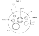
- FIG. 2 is an elevational view of a distal end face 10A of the distal end portion 10 of the endoscope 1
- FIG. 3 is a sectional view of the distal end portion 10 of the endoscope 1 taken along a longitudinal direction.
- the distal end face 10A of the distal end portion 10 includes an observation optical member (hereinafter referred to as an observation window) 15 (let the observation window of the first endoscope 1a be a first observation window 15a, and let the observation window of the second endoscope 1b be a second observation window 15b), two illumination optical members (hereinafter referred to as illumination window) 50 and 55 (the first endoscope 1a has two illumination windows 50a and 55a, and the second endoscope 1b has two illumination windows 50b and 55b), a treatment instrument channel opening 17, an air/water nozzle 18, and a front water opening 19.
- the two illumination optical members 50 and 55 are arranged around the observation window, and the air/water nozzle 18 supplies air or water to the observation window 15.
- first endoscope 1a and the second endoscope 1b are connectable to the same exterior device.
- first endoscope 1a and the second endoscope 1b are connectable to at least one of the processor 11 and the light source 5.
- the distal end portion 10 of the endoscope 1 is formed by a distal end cap 10B and a cylindrical exterior case 10C. Further, an observation optical system 21 (the first endoscope 1a has a viewing angle ⁇ 1 of a first observation optical system 21a, and the second endoscope 1b has a viewing angle ⁇ 2 of a second observation optical system 21b) having a viewing angle ⁇ , which is a fixed viewing angle or the widest viewing angle, is arranged inside the distal end portion 10 of the endoscope 1.
- the observation optical system 21 is formed by plural optical lenses that are arranged from the observation window 15 provided on the distal end face 10A of the distal end cap 10B toward inside the distal end portion 10.
- the solid-state imaging sensor 22 is arranged at a focal point of the observation optical system 21.
- a circuit substrate 23 having a circuit function that controls driving of the solid-state imaging sensor 22 and takes in the imaging signals on which a photoelectrical conversion is performed is connected to a rear side of the solid-state imaging sensor 22.
- the circuit substrate 23 has a CDS circuit 35 and an analog/digital conversion circuit 36 described hereinafter, and a signal cable 24 is connected to the circuit substrate 23.
- a proximal end of the signal cable 24 is connected to the processor 11.
- the treatment instrument channel opening 17 that is provided on the distal end face 10a of the distal end cap 10b is connected to a treatment instrument channel 26 through a treatment instrument insertion channel 25 that is formed in a substantially cylindrical shape.
- the first endoscope 1a can image a region corresponding to a field of view with the viewing angle ⁇ 1 that is, for example, fixed at substantially 140° or the widest angle.
- the observation optical system 21 having the viewing angle ⁇ 2 that is larger than the viewing angle ⁇ 1 of the first endoscope 1a described above is arranged in the distal end portion 10 of the second endoscope 1b ( ⁇ 1 ⁇ ⁇ 2).
- the viewing angle ⁇ 2 is, for example, fixed at substantially 170° or the widest angle.
- the second endoscope 1b can image a region corresponding to a field of view that is wider than the region corresponding to the field of view of the first endoscope 1a.
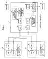
- FIG. 4 is a block diagram showing a major configuration of the endoscope system 100 according to the present embodiment.
- the endoscope system 100 has the first endoscope 1a, the second endoscope 1b, the processor 11, the monitor 7, and the light source 5 (see FIG. 1).
- the first endoscope 1a and the second endoscope 1b are connectable to the same exterior device, and in the present embodiment, the first endoscope 1a and the second endoscope 1b are connectable to at least one of the processor 11 and the light source 5.
- the first endoscope 1a and the second endoscope 1b are employed (configured for observation) for a same region (for example, large intestine) in a subject body.
- the first endoscope 1a has a first observation optical system 21a, a first solid-state imaging sensor (hereinafter referred to as first CCD) 22a, a CDS circuit 35, and an analog/digital conversion circuit (hereinafter referred to as A/D circuit) 36.
- the first observation optical system 21a is formed by plural lenses having mainly the viewing angle ⁇ 1 (for example, substantially 140°).
- the first CCD 22a is arranged at a focal point of the first observation optical system 21a, and images the observation region.
- the CDS circuit 35 performs a correlated double sampling processing on the imaging signals generated by the first CCD 22a.
- the analog/digital conversion circuit 36 converts analog imaging signals processed at the CDS circuit 35 to digital imaging signals.
- the second endoscope 1b has a second observation optical system 21b, a second solid-state imaging sensor (hereinafter referred to as second CCD) 22b, the CDS circuit 35, and the analog/digital conversion circuit 36.
- the second observation optical system 21b is formed by plural lenses having mainly the viewing angle ⁇ 2 (for example, substantially 170°) that is larger than the viewing angle of the first observation optical system 21a of the first endoscope 1a ( ⁇ 1 ⁇ ⁇ 2).
- the second CCD 22b is arranged at a focal point of the second observation optical system 21b, and images the observation region.
- the CDS circuit 35 performs the correlated double sampling processing on the imaging signals generated by the second CCD 22b.
- the analog/digital conversion circuit 36 converts analog imaging signals processed at the CDS circuit 35 to digital imaging signals.
- the first observation optical system 21a is arranged on a central axis of the first observation window 15a described hereinbefore, and the second observation optical system 21b is arranged on a central axis of the second observation window 15b described hereinbefore.
- an optical axis of the first observation optical system 21a coincides with the central axis of the first observation window 15a
- an optical axis of the second observation optical system 21b coincides with the central axis of the second observation window 15b.
- the optical axis of the first observation optical system 21a is parallel to each central axis of the illumination windows 50a and 55a described hereinbefore
- the optical axis of the second observation optical system 21b is parallel to each central axis of the illumination windows 50b and 55b described hereinbefore.
- the processor 11 includes a separating processing circuit (hereinafter referred to as S/P circuit) 41, a digital signal processing circuit (hereinafter referred to as DSP circuit) 42, a textual information superposing circuit 43, a textual information inputting circuit 44, a digital/analog signal conversion circuit (hereinafter referred to as D/A circuit) 45, an image displaying signal circuit 46, a reference signal generator circuit (hereinafter referred to as SSG) 47, a timing signal generator circuit (hereinafter referred to as T/G circuit) 48, and a display-image-switching inputting circuit 49.
- S/P circuit separating processing circuit
- DSP circuit digital signal processing circuit
- D/A circuit digital/analog signal conversion circuit
- T/G circuit timing signal generator circuit
- the S/P circuit 41 separates luminance signals, color signals, and the like of the digital imaging signals from the A/D circuit 36 of the first endoscope 1a or from the A/D circuit 36 of the second endoscope 1b.
- the DSP 42 performs predetermined digital signal processing as well as correction processing such as white balance correction and y correction with respect to the luminance signals and the color signals separated at the S/P circuit 41, to generate digital endoscope image signals.
- the textual information superposing circuit 43 superposes textual information signals indicating patient information such as, name, age, and gender of a patient and date and time of the endoscope observation, on the digital endoscope image signals that are signals processed at the DSP circuit 42.
- the textual information signals that is to be superposed at the textual information superposing circuit 43 is generated from the patient information that is input by the operator through a keyboard (not shown) at the textual information inputting circuit 44.
- the digital endoscope image signals on which the textual information is superposed at the textual information superposing circuit 43 is converted to analog endoscope image signals at the D/A circuit 45, and then output to the image displaying signal circuit 46.
- the digital endoscope image signals on which the generated textual information signals are superposed at the textual information superposing circuit 43 is recorded in a memory 30 that is detachably provided on the processor 11.
- the image displaying signal circuit 46 converts the analog endoscope image signals supplied from the D/A circuit 36 to image signals that are employed for displaying the observation image and the patient information on the monitor 7.
- the image displaying signal circuit 46 changes display positions of the observation image and the patient information that are to be displayed on the monitor 7 according to control signals from the display-image-switching inputting circuit 49.
- a command for switching the displaying such as a command for changing the display position, not shown, of the observation image and the patient information that are to be displayed on the monitor 7 by the operator can be input into the display-image-switching inputting circuit 49.
- the SSG circuit 47 generates and outputs reference signals that control drivings of the S/P circuit 41, the DSP circuit 42, the textual information superposing circuit 43, the D/A circuit 45, and the image displaying signal circuit 46.
- the T/G circuit 48 generates timing signals to drive control each of the first CCD 22a and the second CCD 22b of the first and the second endoscopes 1a and 1b based on the reference signals from the SSG circuit 47.
- FIG. 5 is a longitudinal sectional view of the distal end portion 10 of the first endoscope 1a along the longitudinal direction thereof along a plane passing through each of the centers of window faces of illumination windows 50a and 55a and a center of a window face of the first observation window 15a.
- FIG. 6 is a longitudinal sectional view of the distal end portion 10 of the second endoscope 1b along the longitudinal direction thereof along a plane passing through each of the centers of window faces of illumination windows 50b and 55b and a center of a window face of the second observation window 15b.
- each of the illumination windows 50a and 55a on the distal end portion 10 of the first endoscope 1a has illumination lenses 53a.
- a light guide bundle 50A runs through the endoscope 1 from a proximal end of each illumination lens 53a, and the light guide bundle 50A is connected to the light source 5.
- an illumination optical system includes the illumination windows 50a, 55b, and the illumination lens 53a, and illuminating light from the light guide bundle, which is an illuminating member, runs through the illumination optical system.
- a central axis (central axis of the illumination region of the illuminating light) of the illumination window 50a of the first endoscope 1a is arranged at a position so as to be separated by a predetermined length La from a central axis, which is an optical axis of the first observation window 15a.
- the illumination window 55a of the first endoscope 1a is arranged at a position so as to be separated by a predetermined length Lb from the central axis of the first observation window 15a. Further, the central axis of the first observation window 15a coincides with an optical axis MA1 of a first observation optical system 21a.
- the central axis of the illumination window 50a coincides with a central axis LA1 of the illumination region of the illuminating light
- the central axis of the illumination window 55a coincides with a central axis LA2 of the illumination region of the illuminating light.
- the central axis LA1 and the optical axis MA1 are separated by the predetermined length La
- the central axis LA2 and the optical axis MA1 are separated by the predetermined length Lb.
- the light guide bundle 50A that is to be bundled runs through the insertion portion 3 and the universal cord 3a from each lens face of a proximal end side of the illumination lenses 53a to the connector portion 4.
- the light guide bundle 50A that runs to the connector portion 4 is connected to the light source 5 by the connector portion 4 described above.
- the illuminating light that is supplied from the light source 5 is emitted from two distal end faces of the light guide bundle 50A.
- the illuminating light having the central axis LA1 that passes through the illumination lens 53a is emitted from the illumination window 50a.
- the illuminating light having the central axis LA2 that passes through the illumination lens 53a is emitted from the illumination window 50b.
- each of the illumination windows 50b and 55b on the distal end portion 10 of the second endoscope 1b has illumination lenses 53b.
- the light guide bundle 50A that is connected to the light source 5 runs through the endoscope 1 from a proximal end of each illumination lens 53b.
- an illumination optical system includes the illumination windows 50b, 55b, and the illumination lens 53a, and illuminating light from the light guide bundle 50A, which is an illuminating member, passes through the illumination optical system.
- a central axis LA3 (central axis of the illumination region of the illuminating light) of the illumination window 55a of the distal end face 10a of the second endoscope 1b is arranged at a position so as to be separated by a predetermined length Ld from an optical axis MA2 of the second observation window 15b.
- the illumination window 55b is arranged at a position so as to be separated by a predetermined length Le from the optical axis MA2 of the second observation window 15b.
- the central axis of the second observation window 15b coincides with the optical axis MA2 of the second observation optical system 21b.
- the central axis of the illumination window 50b coincides with the central axis LA3 of the illuminating light
- the central axis of the illumination window 55b coincides with the central axis LA4 of the illuminating light.
- the central axis LA3 and the optical axis MA2 are separated by the predetermined length Ld
- the central axis LA4 and the optical axis MA2 are separated by the predetermined length Le.
- the distances Ld and Le is longer than one of the lengths La and Lb that has the longest distance among the lengths La and Lb.
- the length Ld is the separation between the illumination window 50b of the second endoscope 1b and the second observation window 15b
- the length Le is the separation between the illumination window 55b of the second endoscope 1b and the second observation window 15b.
- the length La is the separation between the illumination window 50a of the first endoscope 1a and the first observation window 15a
- the length Lb is the separation between the illumination window 55a of the first endoscope 1a and the first observation window 15a.
- one of the lengths Ld and Le of the second endoscope 1b is longer than one of the lengths La and Lb of the first endoscope 1a that is the longest among the lengths La and Lb (La ⁇ Ld, Lb ⁇ Ld or La ⁇ Le, Lb ⁇ Le).
- the illuminating light that is supplied from the light source 5 is emitted from the two distal end faces of the light guide bundle 50A. Then, one of the two illuminating light having the central axis LA1 that passes through one of the two illumination lenses 53b is emitted from the illumination window 50b, and other illuminating light having the central axis LA2 that passes through other illumination lens 53b is emitted from the illumination window 55b.
- the illumination lenses 53a, 53b, and the light guide bundle 50A of the first endoscope 1a and the second endoscope 1b of FIGS. 7 to 9 described hereinafter have the same aforementioned configuration.
- light flux of the illuminating light emitted from the two illumination lenses 53a of the first endoscope 1a is the same as light flux of the illuminating light emitted from the two illumination lenses 53b of the second endoscope 1b.
- the light source 5 has a light intensity controlling unit, not shown, that modulates a preliminarily set predetermined light intensity of the illuminating light by detecting brightness of the observation image that is displayed on the monitor screen 7a.
- the light intensity controlling unit automatically modulates the light intensity to increase or decrease.
- the arbitrary imaging distance L1 is an arbitrary imaging distance between the window face on an observation side of the first observation window 15a of the first endoscope 1a and the plain face P1 that is orthogonal to the optical axis MA1 and between the window face on an observation side of the second observation window 15b of the second endoscope 1b and the plain face P1 that is orthogonal to the optical axis MA2.
- the first imaging region A is a region corresponding to a field of view with the viewing angle ⁇ 1 of the first endoscope 1a.
- the region is shown by two radial dotted lines LR1 in FIG. 5.
- the first imaging region A on the plain face P1 at the arbitrary imaging distance L1 is included in an illumination region that is illuminated with the illuminating light having an illuminance that is greater than or equal to a predetermined illuminance.
- the illuminating light is emitted from the two illumination windows 50a and 55a, and shown by radial dotted lines LX1 and LX 2 in FIG. 5.
- the radial dotted line LX1 shows a boundary line of the predetermined illuminance of the illuminating light emitted from the illumination window 50a
- the radial dotted line LX2 shows a boundary line of the predetermined illuminance of the illuminating light emitted from the illumination window 55a.
- the radial dotted line LX1 is referred to as a first boundary line LX1
- the radial dotted line LX2 is referred to as a second boundary line LX2.
- a second imaging region B is displayed on the monitor screen 7a.
- the second imaging region B is a region within the viewing angle ⁇ 2 of the second endoscope 1b.
- the region is shown by two radial dotted lines LR2 in FIG. 6.
- the imaging region B on the plain face P1 at the arbitrary imaging distance L1 is substantially included in an illumination region that is illuminated with the illuminating light having the illuminance that is greater than or equal to the predetermined illuminance.
- the illuminating light is emitted from the two illumination windows 50b and 55b, and shown by radial dotted lines LX3 and LX4 in FIG. 6.
- the radial dotted line LX3 shows a boundary line of the predetermined illuminance of the illuminating light emitted from the illumination window 50b
- the radial dotted line LX4 shows a boundary line of the predetermined illuminance of the illuminating light emitted from the illumination window 55b.
- the radial dotted line LX3 is referred to as a third boundary line LX3
- the radial dotted line LX4 is referred to as a fourth boundary line LX4.
- FIG. 7 is a drawing illustrating a state in which the first imaging region A is displayed on the monitor screen 7a, and as the first imaging region A, the first endoscope 1a images the plain face P1 at the arbitrary imaging distance L1.
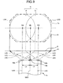
- FIGS. 8 and 9 are drawings illustrating a state in which the second imaging region B is displayed on the monitor screen 7a, and as the second imaging region B, the second endoscope 1b images the plain face P1 at the arbitrary imaging distance L1.
- the first imaging region A that is displayed on the monitor screen 7a is included in the illumination region bounded by the first boundary line LX1 and the illumination region bounded by the second boundary line LX2, as shown in FIG. 7.
- each illumination region is illuminated with the illuminating light having the illuminance that is greater than or equal to the predetermined illuminance.
- the first imaging region A is included in a first illumination region Ia, which is formed by illumination regions I1 and I2, having overall illuminance that is greater than or equal to the predetermined illuminance.
- the illumination region I1 is a light distribution region of the illuminating light, which is emitted from the illumination window 50a, with the illuminance that is greater than or equal to the predetermined illuminance, and the illumination region I1 has a point M1 through which the central axis LA1 passes.
- the illumination region I2 is a light distribution region of the illuminating light, which is emitted from the illumination window 55a, with the illuminance that is greater than or equal to the predetermined illuminance, and the illumination region I2 has a point M2 through which the central axis LA1 passes. Both of the light distribution regions are on the plain face P1. Further, one portion of the illumination region I1 and one portion of the illumination region I2 are superposed on each other.
- the entire first imaging region A of the first endoscope 1a at the arbitrary imaging distance L1 is illuminated with the illuminating light having the illuminance that is greater than or equal to the predetermined illuminance. Consequently, the entire image on the monitor screen 7a has brightness that is greater than or equal to the predetermined illuminance.
- a letter Ma in FIG. 7 represents a point at which the optical axis MA1 of the first endoscope 1a intersects with the first imaging region A. Since the optical axis MA1 and the two central axes LA1 and LA2 are parallel to each other, the distance between the point Ma and the point M1 is the length La and the distance between the point Mb and the point M1 is the length Lb.
- the points Ma, Mb, M1, and M2 are on the first imaging region A, which is on the plain face P1 at the imaging distance L1 of the first endoscope 1a.
- the second endoscope 1b when the second endoscope 1b images the plain face P1 at the imaging distance L1, the second endoscope 1b can display the second imaging region B which is wider than the first imaging region A of the first endoscope 1a, on the monitor screen 7a, since the second endoscope 1b has the second observation optical system 21b with the viewing angle ⁇ 2 which is wider than the viewing angle ⁇ 1 of the first endoscope 1a.
- a first illumination region Ia that is the same as the first illumination region Ia of the first endoscope 1a is formed on the plain face P1 of the second endoscope 1b when the second endoscope 1b has the two central axes LA3 and LA4 that are each separated by the lengths La and Lb, respectively.
- the lengths La and Lb of the second endoscope 1b are the same as the lengths La and Lb of the first endoscope 1a
- the length La and Lb are the separations between the optical axis MA1 and each of the central axes LA1 and LA2, respectively.
- a ratio in which the second imaging region B is included in the second illumination region Ib that is illuminated with the illuminating light having the illuminance that is greater than or equal to the predetermined illuminance by the second endoscope 1b is less than a ratio in which the first imaging region A is included in the first illumination region Ia that is illuminated with the illuminating light having the illuminance that is greater than or equal to the predetermined illuminance by the first endoscope 1a.
- the second endoscope 1b cannot illuminate a surrounding portion on the second imaging region B that is to be imaged with the illuminating light having the illuminance that is greater than or equal to the predetermined illuminance.
- the monitor screen 7a that is displayed by the second endoscope 1b displays the surrounding portion darker than the surrounding portion on the monitor screen 7a that is displayed by the first endoscope.
- the distance between the optical axis MA2 and one of the central axes LA3 and LA4 of the second endoscope 1b is set to be longer than the longest distance among the distances between the optical axis MA1 and the central axis LA1 of the first endoscope 1a and between the optical axis MA1 and the central axis LX2 of the first endoscope 1a.
- the distances just mentioned are set as described above in order to substantially include the second imaging region B that is displayed on the display 7a in the illumination region that is bounded by the third boundary line LX3 and in the illumination region that is bounded by the fourth boundary line LX4.
- each of the two illumination regions just mentioned is illuminated by the illuminating light having the illuminance that is greater than or equal to the predetermined illuminance.
- the second imaging region B is substantially included in the second illumination region Ib in which the entire region thereof is illuminated with the illuminating light having the illuminance that is greater than or equal to the predetermined illuminance.
- the illumination region Ib is formed by an illumination region I3 and an illumination region I4.
- the illumination region I3 is a light distribution region of the illuminating light, which is emitted from the illumination window 50b onto the plain face P1, with the illuminance that is greater than or equal to the predetermined illuminance.
- the illumination region 14 is a light distribution region of the illuminating light, which is emitted from the illumination window 55b onto the plain face P1, with the illuminance that is greater than or equal to the predetermined illuminance. Further, the illumination region 13 has a point M3 through which the central axis LA3 passes, and the illumination region 14 has a point M4 through which the central axis LA4 passes. A portion of the illumination region I3 and a portion of the illumination region I4 are superposed on each other.
- the distances between the optical axis MA2 and the central axis LA3 and between the optical axis MA2 and the central axis LA4 are determined in order to illuminate a surrounding portion on the second imaging region B of the second endoscope 1b at the arbitrary imaging distance L1 with the illuminating light having the illuminance that is greater than or equal to the predetermine illuminance. Then, positions of the second observation window 15b and the two illumination windows 50b and 55b, which are to be arranged on the distal end face 10a, are determined.
- the second endoscope 1b can display the observation image so as to include the surrounding portion in the predetermined brightness that is substantially the same as the predetermined brightness on the monitor screen 7a that is displayed by the first endoscope.
- the letter Mb in FIG. 9 represents a point at which the optical axis MA2 of the second endoscope 1b intersects with the second imaging region B. Since the optical axis MA2 and the two central axes LA3 and LA4 are parallel to each other, the distance between the points Mb and M3 is the length Ld and the distance between the points Mb and M4 is the length Le.
- the points Mb, M3, and M4 are on the second imaging region B, which is on the plain face P1 at the imaging distance L1 of the second endoscope 1b.
- one of the lengths Ld and Le of the second endoscope 1b is longer than one of the lengths La and Lb of the first endoscope 1a that is the longest among the lengths La and Lb (La ⁇ Ld, Lb ⁇ Ld or La ⁇ Le, Lb ⁇ Le).
- the second illumination region Ib on the plain face P1 at the arbitrary imaging distance L1 of the second endoscope 1b is wider than the first illumination region Ia on the plain face P1 at the arbitrary imaging distance L1 of the first endoscope 1a.
- the second endoscope 1b can illuminate the illumination region, which is wider than the illumination region of the first endoscope 1a, on the plain face P1 at the arbitrary imaging distance L1 with the illuminating light having the illuminance that is greater than or equal to the predetermined illuminance.
- the surrounding portion on the second imaging region B of the second endoscope 1b is illuminated with the illuminating light having the illuminance that is greater than or equal to the predetermined illuminance when the second endoscope 1b and the first endoscope 1a are employed.
- the second endoscope 1b has the second observation optical system 21b having the viewing angle ⁇ 2
- the first endoscope 1a has the first observation optical system 21a having the viewing angle ⁇ 1. Therefore, the first imaging region A that is displayed on the monitor screen 7a by the first endoscope 1a and the second imaging region B that is displayed on the monitor screen 7a by the second endoscope 1b have substantially the same brightness.
- the operator does not feel uncomfortableness due to the difference in the brightness at the surrounding portion on the image that is displayed on the monitor screen 7a when the second endoscope 1b is employed before/after employing the first endoscope 1a.
- the operator does not feel uncomfortableness due to the difference in the brightness at the surrounding portion on the monitor screen 7a when the second endoscope 1b is employed before/after employing the first endoscope 1a.
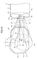
- FIG. 10 is a drawing illustrating a state in which the second imaging region B is displayed on the monitor screen 7a by the second endoscope 1b at the arbitrary imaging distance L1.
- Configurations, effects, and advantages of the second endoscope 1b and the monitor screen 7a in FIG. 11 are the same as those of the aforementioned second endoscope 1b and the monitor screen 7a. Therefore, explanations of the configurations, the effects, and the advantages are not to be repeated.
- a radial dotted line LX5 of FIG. 10 shows a boundary line of a predetermined illuminance of illuminating light that is emitted from the illumination window 55c. Further, the radial dotted line LX5 is referred to as a second boundary line LX5.
- a second illumination region Ic in which an entire region thereof is illuminated with the illuminating light having the illuminance that is greater than or equal to the predetermined illuminance is formed by an illumination region I5 and the illumination regions I3 and I4.
- the illumination region I5 is a region of the illuminating light, which is emitted from the illumination window 56b, with the illuminance that is greater than or equal to the predetermined illuminance.
- the illumination region 15 is on the second imaging region B, and the illumination region 15 has a point M5 through which a central axis LA5 passes.
- a plane of the second imaging region B is substantially included in a plane of the third illumination region Ic.
- the distances between the optical axis MA2 and each of the central axes LA3, LA4, and LA5 are determined in order to illuminate a surrounding portion on the second imaging region B of the second endoscope 1b at the arbitrary distance L1 with the illuminating light having the illuminance that is greater than or equal to the predetermined illuminance. Then, positions of the second observation window 15b and the three illumination windows 50b, 55b, and 56b that are to be arranged on the distal end face 10a are determined.
- the third illumination region Ic on the plain face P1 at the arbitrary imaging distance L1 of the second endoscope 1b is wider than the first illumination region Ia on the plain face P1 at the arbitrary distance L1 of the first endoscope 1a.
- the second endoscope 1b can illuminate the illumination region, which is wider than the illumination region of the first endoscope 1a, on the plain face P1 at the arbitrary imaging distance L1 with the illuminating light having the illuminance that is greater than or equal to the predetermined illuminance.
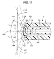
- FIG. 11 is a longitudinal sectional view of the distal end portion 10 of the second endoscope 1b along a longitudinal direction thereof along a plane passing through each of centers of window faces of the illumination windows 50b, 55b, and a center of a window face of the second observation window 15b.
- FIG. 12 is a drawing illustrating a state in which the second imaging region B is displayed on the monitor screen 7a, and as the second imaging region B, the second endoscope 1b images the plain face P1 at the arbitrary imaging distance L1.
- the second endoscope 1b has two illumination lenses 53b in which optical axes thereof are pointed towards a surrounding on the second imaging region B.
- the two illumination lenses 53b are arranged respectively at the two illumination windows 50b and 55b.
- the second endoscope 1b has the central axes LA3 and LA4.
- the central axis LA3 is inclined with respect to the optical axis MA2 of the second observation optical system 21b by a predetermined angle of inclination ⁇ 1
- the central axis LA4 is inclined with respect to the optical axis MA2 of the second observation optical system 21b by a predetermined angle of inclination ⁇ 2.
- the illumination window 50b through which the central axis LA3 passes has one window face with the angle of inclination ⁇ 1 and other window face with the angle of inclination ⁇ 2.
- the angle of inclination ⁇ 1 is an angle between the one window face and the window face of the second observation window 15b through which the optical axis MA2 passes.
- the angle of inclination ⁇ 2 is an angle between the other window face and the window face of the second observation window 15b through which the optical axis passes.
- the second imaging region B which is included in the illuminating light with the illuminance that is greater than or equal to the predetermined illuminance when the plain face P1 at the arbitrary imaging distance L1 is imaged by the second endoscope 1b, is explained with reference to FIG. 11.
- a region that is displayed on the monitor screen 7a is explained.
- the second imaging region B that is displayed on the monitor screen 7a is substantially included in an illumination region that is bounded by the third boundary line LX3 and an illumination region that is bounded by the fourth boundary line LX4.
- each illumination region is illuminated with the illuminating light having the illuminance that is greater than or equal to the predetermined illuminance.
- the optical axis MA1 and the two central axes LA1 and LA2 are parallel to each other, so that the distances between the point Ma and each of the point M1 and the point M2 on the first imaging region A is the lengths La and Lb, respectively.
- the length La is the distance between the optical axis MA1 and the central axis LA1
- the length Lb is the distance between the optical axis MA1 and the central axis LA2. Therefore, by setting one of lengths Ld1 and Ld2 to be longer than the longest length among the two lengths La and Lb, an area of the second illumination region Id that is formed by the illumination regions I3 and I4 of the second endoscope Ib can be set to be larger than an area of the first illumination region Ia of the first endoscope.
- the two lengths La and Lb are the distances between the optical axis MA1 of the first endoscope 1a and the central axes LA1 and LX2, respectively.
- the two lengths Ld1 and Ld2 are the distance between the point Mb and the points M3 and M4 on the second imaging region B of the second endoscope 1b, respectively.
- a relationship between the lengths Ld and Le, with respect to the lengths La and Lb on the illumination region 11 of the first endoscope 1a, on the second illumination region Id of the second endoscope 1b is explained hereinafter.
- one of the lengths Ld and Le of the second endoscope 1b is longer than the longest distance among the lengths La and Lb of the first endoscope 1a (La ⁇ Ld, Lb ⁇ Ld or La ⁇ Le, Lb ⁇ Le).
- the second illumination region Id on the plain face P1 at the imaging distance L1 of the second endoscope 1b is wider than the first illumination region Ia on the plain face P1 at the arbitrary imaging distance L1 of the first endoscope 1a.
- the second endoscope 1b can illuminate the illumination region, which is wider than the illumination region of the first endoscope 1a, on the plain face P1 at the arbitrary imaging distance L1 with the illuminating light having the illuminance that is greater than or equal to the predetermined illuminance.
- the second endoscope 1b can display the image on the monitor screen 7a so that the second endoscope 1b substantially includes the surrounding portion in the predetermined brightness that is substantially the same as the brightness on the monitor screen 7a that is displayed by the first endoscope.
- the endoscope system 100 of the present embodiment can obtain the effect that is the same as the effect of the endoscope system 100 of the first embodiment.
- the illumination region may be illuminated with illuminating light having an angle of illumination that is wider than an angle of illumination of the illuminating light of the first endoscope 1a.
- the second endoscope 1b has at least one illumination optical system that can illuminate the illumination region, which is wider than the illumination region of the illuminating light having the illuminance that is greater than or equal to the predetermined illuminance of the first endoscope 1a, with the illuminating light having the illuminance that is greater than or equal to the predetermined illuminance.
- a diode which is a light emitting element, can be employed as the illumination member arranged at the distal ends of the endoscopes 1a and 1b.
- the diode illuminates the illumination region with the illuminating light having the illuminance that is greater than or equal to the predetermined illuminance, and the illuminating light has a central axis of the illumination region at the arbitrary imaging distance L1.
- an endoscope system according to the present invention is especially useful for an endoscope system that includes two endoscopes having viewing angles that is different from each other.
Landscapes
- Physics & Mathematics (AREA)
- Health & Medical Sciences (AREA)
- Life Sciences & Earth Sciences (AREA)
- Surgery (AREA)
- Optics & Photonics (AREA)
- Biomedical Technology (AREA)
- Public Health (AREA)
- Nuclear Medicine, Radiotherapy & Molecular Imaging (AREA)
- Pathology (AREA)
- Radiology & Medical Imaging (AREA)
- Veterinary Medicine (AREA)
- Engineering & Computer Science (AREA)
- Molecular Biology (AREA)
- Biophysics (AREA)
- Medical Informatics (AREA)
- Heart & Thoracic Surgery (AREA)
- Animal Behavior & Ethology (AREA)
- General Health & Medical Sciences (AREA)
- General Physics & Mathematics (AREA)
- Astronomy & Astrophysics (AREA)
- Endoscopes (AREA)
- Instruments For Viewing The Inside Of Hollow Bodies (AREA)
Abstract
Description
- The present invention relates to an endoscope, and more particularly to an endoscope system including two endoscopes that are different from each other in viewing angle.
- Conventionally, an endoscope has been widely used in a medical field and the like. The endoscope is employed to observe organs and the like inside a body cavity by inserting an elongate insertion portion into the body cavity, and to operate various treatments by using a treatment instrument that is inserted into a treatment instrument insertion channel, if necessary. A bendable portion is provided at a distal end of the insertion portion, and an observation direction of an observation window of the distal end portion is changed by manipulating a manipulating portion of the endoscope.
- A viewing angle of the conventional endoscope is, for example, 140° (degree), and an operator observes inside the body cavity by an observation image corresponding to the viewing angle. When the operator desires to observe a region outside a region corresponding to a field of view during the observation inside the body cavity, the operator can bend the bendable portion to observe such region.
- On the other hand, an endoscope having a wider viewing angle has been proposed to allow an observation of a wider region. The endoscope has an advantage that the observation is easily performed and a region necessary to be treated is easily found since an imaging region is widened by having the wide viewing angle (for example, see Patent Document 1).
- Patent Document 1:
Japanese Patent Application Laid-Open No. H4-102432 - The endoscope having the wide viewing angle according to the proposal in
Japanese Patent Application Laid-Open No. H4-102432 - Therefore, an object of the present invention is to provide an endoscope system that achieves high observability while employing both an endoscope having a normal viewing angle and an endoscope having a wide viewing. angle. The high observability is obtained by distributing illuminating light with a predetermined illuminance even to a surrounding portion on an imaging region so that a difference in brightness between a dark region and a bright region of an image displayed on a monitor screen is reduced.
- An endoscope system according to the present invention includes a first endoscope having a first observation optical system with a first viewing angle and a first illumination optical system; and a second endoscope having a second observation optical system with a second viewing angle wider than the first viewing angle and a second illumination optical system, wherein a second illumination region of illuminating light that is emitted by the second illumination optical system and has a predetermined illuminance is wider than a first illumination region of illuminating light that is emitted by the first illumination optical system and has a predetermined illuminance, at any imaging distance that is pointed in an observation direction from a distal end of an insertion portion of each of the first endoscope and the second endoscope.
- An endoscope system according to the present invention can achieve high observability while employing an endoscope having a normal viewing angle and an endoscope having a wide viewing angle. The high observability is obtained by reducing a difference in brightness among respective imaging faces displayed on a monitor screen.
-
- FIG. 1 is an explanatory view schematically showing an endoscope system according to a first embodiment;
- FIG. 2 is an elevational view of a distal end face of a distal end portion of an endoscope;
- FIG. 3 is a longitudinal sectional view of the distal end portion of the endoscope;
- FIG. 4 is a block diagram showing a major configuration of the endoscope system according to the first embodiment;
- FIG. 5 is a longitudinal sectional view of the distal end portion of a first endoscope along a plane passing through each center of window faces of illumination windows and a center of a window face of a first observation window;
- FIG. 6 is a longitudinal sectional view of the distal end portion of a second endoscope along a plane passing through each center of window faces of illumination windows and a center of a window face of a second observation window;
- FIG. 7 is a drawing illustrating a state in which an imaging region is displayed on a monitor screen, and as the imaging region, the first endoscope images a plain face at an arbitrary imaging distance;
- FIG. 8 is a drawing illustrating a state in which an imaging region is displayed on the monitor screen, and as the imaging region, the
second endoscope 1b images the plain face at the arbitrary imaging distance; - FIG. 9 is a drawing illustrating a state in which an imaging region is displayed on the monitor screen, and as the imaging region, the
second endoscope 1b images the plain face at the arbitrary imaging distance; - FIG. 10 is a drawing illustrating a state in which an imaging region at the arbitrary imaging distance is displayed on the monitor screen by the second endoscope;
- FIG. 11 is a longitudinal sectional view of a distal end portion of the second endoscope of a second embodiment along a plane passing through each center of window surfaces of illumination windows and a center of a window face of the second observation window; and
- FIG. 12 is a drawing illustrating a state in which an imaging region is displayed on a monitor screen, and as the imaging region, the second endoscope at the arbitrary imaging distance images the plain face.
-
- 1, 1a, 1b
- Endoscope
- 2
- Manipulating portion
- 3
- Insertion portion
- 3a
- Universal cord
- 4
- Connector portion
- 5
- Light source
- 7
- Monitor
- 7a
- Monitor screen
- 8
- Flexible tube portion
- 9
- Bendable portion
- 10
- Distal end portion
- 10a
- Distal end face
- 10b
- Distal end cap
- 10c
- Exterior case
- 11
- Video processor
- 15
- Observation window
- 15a
- First observation window
- 15b
- Second observation window
- 17
- Treatment instrument channel opening
- 18
- Air/water nozzle
- 19
- Front water opening
- 21
- Observation optical system
- 21a
- First observation optical system
- 21b
- Second observation optical system
- 22
- Solid-state imaging sensor
- 23
- Circuit substrate
- 24
- Signal cable
- 25
- Treatment instrument insertion channel
- 26
- Treatment instrument channel
- 30
- Memory
- 35
- CDS circuit
- 36
- Digital conversion circuit
- 41
- Separating processing circuit
- 42
- Digital signal processing circuit
- 43
- Textual information superposing circuit
- 44
- Textual information inputting circuit
- 45
- Digital/analog signal conversion circuit
- 46
- Image displaying signal circuit
- 47
- Reference signal generator circuit
- 48
- Timing signal generator circuit
- 49
- Display-image-switching inputting circuit
- 50A
- Light guide bundle
- 53a, 53b
- Illumination lens
- 55
- Illumination window
- 100
- Endoscope system
- A
- First imaging region
- B
- Second imaging region
- I1, I2, I3, I4, I5, Ia, Ib, Ic, Id
- Illumination region
- L1
- Arbitrary imaging distance
- LA1, LA2, LA3, LA4, LA5
- Central axis
- LX1
- First boundary line
- LX2
- Second boundary line
- LX3
- Third boundary line
- LX4
- Fourth boundary line
- LX5
- Fifth boundary line
- MA1, MA2
- Optical axis
- P1
- Plain face
- α, α1, α2
- Viewing angle
- θ1, θ2
- Angle of inclination
- Exemplary embodiments of the present invention are explained with reference to the drawings hereinafter.
A configuration of anendoscope system 100 according to the present embodiment is explained with reference to FIG. 1. FIG. 1 is an explanatory view schematically showing theendoscope system 100 according to the present embodiment of the present invention. As shown in FIG. 1, afirst endoscope 1a and asecond endoscope 1b (hereinafter referred to as afirst endoscope 1 when the two endoscopes are not specifically distinguished) includes a manipulatingportion 2, aninsertion portion 3, and a universal cord 3a. The manipulatingportion 2 controls bending manipulation and a channel system. Theinsertion portion 3 is inserted into a body cavity while a proximal end side thereof is connected to the manipulatingportion 2. The universal cord 3a is extended from the manipulatingportion 2, and the universal cord 3a has aconnector portion 4 at a distal end thereof. Theconnector portion 4 is connected to alight source 5 and aprocessor 11, which are exterior devices, through a predetermined connector. Theprocessor 11 is connected to amonitor 7. Thefirst endoscope 1a and thesecond endoscope 1b can be connected to theprocessor 11 and thelight source 5 through the connector if necessary, or each of thefirst endoscope 1a and thesecond endoscope 1b may be kept connected to theprocessor 11 and thelight source 5 through the connector, and the connection to each of the endoscopes is switched by a switch not shown. - The
insertion portion 3 has aflexible tube portion 8 that has flexibility, abendable portion 9 that is provided at a distal end side of theflexible tube portion 8, and adistal end portion 10 that is provided at a distal end side of thebendable portion 9. A solid-state imaging sensor 22 (see FIG. 2) for imaging a region inside the body cavity is installed in thedistal end portion 10. - Image signals of the region inside the body cavity imaged by the solid-
state imaging sensor 22 that is provided in thedistal end portion 10 are transmitted to theprocessor 11 through the universal cord 3a. As described hereinafter, theprocessor 11 displays an observation image of the imaged region on amonitor screen 7a of themonitor 7 based on signals that are the transmitted processed image signals. Here, themonitor 7 is a display unit that is connected to theprocessor 11. - A manipulating knob (not shown) employed for remotely bending the
bendable portion 9 is arranged on the manipulatingportion 2. A manipulating wire (not shown) that penetrates through theinsertion portion 3 pulls and looses thebendable portion 9 by manipulating the manipulating knob, and as a result, thebendable portion 9 is bendable in four directions. - Next, a configuration of the
distal end portion 10 of theendoscope 1 is explained in details with reference to FIGS. 2 and 3. FIG. 2 is an elevational view of adistal end face 10A of thedistal end portion 10 of theendoscope 1, and FIG. 3 is a sectional view of thedistal end portion 10 of theendoscope 1 taken along a longitudinal direction. - As shown in FIG. 2, the
distal end face 10A of thedistal end portion 10 includes an observation optical member (hereinafter referred to as an observation window) 15 (let the observation window of thefirst endoscope 1a be afirst observation window 15a, and let the observation window of thesecond endoscope 1b be asecond observation window 15b), two illumination optical members (hereinafter referred to as illumination window) 50 and 55 (thefirst endoscope 1a has twoillumination windows second endoscope 1b has twoillumination windows instrument channel opening 17, an air/water nozzle 18, and afront water opening 19. The two illumination optical members 50 and 55 are arranged around the observation window, and the air/water nozzle 18 supplies air or water to theobservation window 15. - Furthermore, the
first endoscope 1a and thesecond endoscope 1b are connectable to the same exterior device. In the present embodiment, thefirst endoscope 1a and thesecond endoscope 1b are connectable to at least one of theprocessor 11 and thelight source 5. - As shown in FIG. 3, the
distal end portion 10 of theendoscope 1 is formed by adistal end cap 10B and a cylindricalexterior case 10C. Further, an observation optical system 21 (thefirst endoscope 1a has a viewing angle α1 of a first observationoptical system 21a, and thesecond endoscope 1b has a viewing angle α2 of a second observationoptical system 21b) having a viewing angle α, which is a fixed viewing angle or the widest viewing angle, is arranged inside thedistal end portion 10 of theendoscope 1. The observationoptical system 21 is formed by plural optical lenses that are arranged from theobservation window 15 provided on thedistal end face 10A of thedistal end cap 10B toward inside thedistal end portion 10. The solid-state imaging sensor 22 is arranged at a focal point of the observationoptical system 21. Acircuit substrate 23 having a circuit function that controls driving of the solid-state imaging sensor 22 and takes in the imaging signals on which a photoelectrical conversion is performed is connected to a rear side of the solid-state imaging sensor 22. Thecircuit substrate 23 has aCDS circuit 35 and an analog/digital conversion circuit 36 described hereinafter, and asignal cable 24 is connected to thecircuit substrate 23. A proximal end of thesignal cable 24 is connected to theprocessor 11. - The treatment
instrument channel opening 17 that is provided on thedistal end face 10a of the distal end cap 10b is connected to atreatment instrument channel 26 through a treatmentinstrument insertion channel 25 that is formed in a substantially cylindrical shape. Further, thefirst endoscope 1a can image a region corresponding to a field of view with the viewing angle α1 that is, for example, fixed at substantially 140° or the widest angle. - The observation
optical system 21 having the viewing angle α2 that is larger than the viewing angle α1 of thefirst endoscope 1a described above is arranged in thedistal end portion 10 of thesecond endoscope 1b (α1 < α2). Here, the viewing angle α2 is, for example, fixed at substantially 170° or the widest angle. In other words, thesecond endoscope 1b can image a region corresponding to a field of view that is wider than the region corresponding to the field of view of thefirst endoscope 1a. - Next, the
endoscope system 100, which has thefirst endoscope 1a and thesecond endoscope 1b, according to the present embodiment is explained with reference to FIG. 4. FIG. 4 is a block diagram showing a major configuration of theendoscope system 100 according to the present embodiment. - The
endoscope system 100 has thefirst endoscope 1a, thesecond endoscope 1b, theprocessor 11, themonitor 7, and the light source 5 (see FIG. 1). Thefirst endoscope 1a and thesecond endoscope 1b are connectable to the same exterior device, and in the present embodiment, thefirst endoscope 1a and thesecond endoscope 1b are connectable to at least one of theprocessor 11 and thelight source 5. Thefirst endoscope 1a and thesecond endoscope 1b are employed (configured for observation) for a same region (for example, large intestine) in a subject body. - The
first endoscope 1a has a first observationoptical system 21a, a first solid-state imaging sensor (hereinafter referred to as first CCD) 22a, aCDS circuit 35, and an analog/digital conversion circuit (hereinafter referred to as A/D circuit) 36. The first observationoptical system 21a is formed by plural lenses having mainly the viewing angle α1 (for example, substantially 140°). Thefirst CCD 22a is arranged at a focal point of the first observationoptical system 21a, and images the observation region. TheCDS circuit 35 performs a correlated double sampling processing on the imaging signals generated by thefirst CCD 22a. The analog/digital conversion circuit 36 converts analog imaging signals processed at theCDS circuit 35 to digital imaging signals. - The
second endoscope 1b has a second observationoptical system 21b, a second solid-state imaging sensor (hereinafter referred to as second CCD) 22b, theCDS circuit 35, and the analog/digital conversion circuit 36. The second observationoptical system 21b is formed by plural lenses having mainly the viewing angle α2 (for example, substantially 170°) that is larger than the viewing angle of the first observationoptical system 21a of thefirst endoscope 1a (α1 < α2). Thesecond CCD 22b is arranged at a focal point of the second observationoptical system 21b, and images the observation region. TheCDS circuit 35 performs the correlated double sampling processing on the imaging signals generated by thesecond CCD 22b. The analog/digital conversion circuit 36 converts analog imaging signals processed at theCDS circuit 35 to digital imaging signals. - The first observation
optical system 21a is arranged on a central axis of thefirst observation window 15a described hereinbefore, and the second observationoptical system 21b is arranged on a central axis of thesecond observation window 15b described hereinbefore. In other words, an optical axis of the first observationoptical system 21a coincides with the central axis of thefirst observation window 15a, and an optical axis of the second observationoptical system 21b coincides with the central axis of thesecond observation window 15b. Furthermore, the optical axis of the first observationoptical system 21a is parallel to each central axis of theillumination windows optical system 21b is parallel to each central axis of theillumination windows - The
processor 11 includes a separating processing circuit (hereinafter referred to as S/P circuit) 41, a digital signal processing circuit (hereinafter referred to as DSP circuit) 42, a textualinformation superposing circuit 43, a textualinformation inputting circuit 44, a digital/analog signal conversion circuit (hereinafter referred to as D/A circuit) 45, an image displayingsignal circuit 46, a reference signal generator circuit (hereinafter referred to as SSG) 47, a timing signal generator circuit (hereinafter referred to as T/G circuit) 48, and a display-image-switchinginputting circuit 49. - The S/
P circuit 41 separates luminance signals, color signals, and the like of the digital imaging signals from the A/D circuit 36 of thefirst endoscope 1a or from the A/D circuit 36 of thesecond endoscope 1b. TheDSP 42 performs predetermined digital signal processing as well as correction processing such as white balance correction and y correction with respect to the luminance signals and the color signals separated at the S/P circuit 41, to generate digital endoscope image signals. - The textual
information superposing circuit 43 superposes textual information signals indicating patient information such as, name, age, and gender of a patient and date and time of the endoscope observation, on the digital endoscope image signals that are signals processed at theDSP circuit 42. The textual information signals that is to be superposed at the textualinformation superposing circuit 43 is generated from the patient information that is input by the operator through a keyboard (not shown) at the textualinformation inputting circuit 44. The digital endoscope image signals on which the textual information is superposed at the textualinformation superposing circuit 43 is converted to analog endoscope image signals at the D/A circuit 45, and then output to the image displayingsignal circuit 46. Here, the digital endoscope image signals on which the generated textual information signals are superposed at the textualinformation superposing circuit 43 is recorded in amemory 30 that is detachably provided on theprocessor 11. - The image displaying
signal circuit 46 converts the analog endoscope image signals supplied from the D/A circuit 36 to image signals that are employed for displaying the observation image and the patient information on themonitor 7. The image displayingsignal circuit 46 changes display positions of the observation image and the patient information that are to be displayed on themonitor 7 according to control signals from the display-image-switchinginputting circuit 49. A command for switching the displaying such as a command for changing the display position, not shown, of the observation image and the patient information that are to be displayed on themonitor 7 by the operator can be input into the display-image-switchinginputting circuit 49. - The
SSG circuit 47 generates and outputs reference signals that control drivings of the S/P circuit 41, theDSP circuit 42, the textualinformation superposing circuit 43, the D/A circuit 45, and the image displayingsignal circuit 46. The T/G circuit 48 generates timing signals to drive control each of thefirst CCD 22a and thesecond CCD 22b of the first and thesecond endoscopes SSG circuit 47. - Next, the
first endoscope 1a and thesecond endoscope 1b are explained further in details with reference to FIGS. 5 and 6. FIG. 5 is a longitudinal sectional view of thedistal end portion 10 of thefirst endoscope 1a along the longitudinal direction thereof along a plane passing through each of the centers of window faces ofillumination windows first observation window 15a. FIG. 6 is a longitudinal sectional view of thedistal end portion 10 of thesecond endoscope 1b along the longitudinal direction thereof along a plane passing through each of the centers of window faces ofillumination windows second observation window 15b. - In the present embodiment, as shown in FIG. 5, each of the
illumination windows distal end portion 10 of thefirst endoscope 1a hasillumination lenses 53a. Alight guide bundle 50A runs through theendoscope 1 from a proximal end of eachillumination lens 53a, and thelight guide bundle 50A is connected to thelight source 5. Further, an illumination optical system includes theillumination windows illumination lens 53a, and illuminating light from the light guide bundle, which is an illuminating member, runs through the illumination optical system. - A central axis (central axis of the illumination region of the illuminating light) of the
illumination window 50a of thefirst endoscope 1a is arranged at a position so as to be separated by a predetermined length La from a central axis, which is an optical axis of thefirst observation window 15a. Theillumination window 55a of thefirst endoscope 1a is arranged at a position so as to be separated by a predetermined length Lb from the central axis of thefirst observation window 15a. Further, the central axis of thefirst observation window 15a coincides with an optical axis MA1 of a first observationoptical system 21a. Furthermore, the central axis of theillumination window 50a coincides with a central axis LA1 of the illumination region of the illuminating light, and the central axis of theillumination window 55a coincides with a central axis LA2 of the illumination region of the illuminating light. In other words, the central axis LA1 and the optical axis MA1 are separated by the predetermined length La, and the central axis LA2 and the optical axis MA1 are separated by the predetermined length Lb. The lengths La and Lb can be the same (La = Lb), or can be different (La ≠ Lb). - Further, in the
first endoscope 1a, thelight guide bundle 50A that is to be bundled runs through theinsertion portion 3 and the universal cord 3a from each lens face of a proximal end side of theillumination lenses 53a to theconnector portion 4. Thelight guide bundle 50A that runs to theconnector portion 4 is connected to thelight source 5 by theconnector portion 4 described above. The illuminating light that is supplied from thelight source 5 is emitted from two distal end faces of thelight guide bundle 50A. Then, the illuminating light having the central axis LA1 that passes through theillumination lens 53a is emitted from theillumination window 50a. Similarly, the illuminating light having the central axis LA2 that passes through theillumination lens 53a is emitted from theillumination window 50b. - In the present embodiment, as shown in FIG. 6, each of the
illumination windows distal end portion 10 of thesecond endoscope 1b hasillumination lenses 53b. Thelight guide bundle 50A that is connected to thelight source 5 runs through theendoscope 1 from a proximal end of eachillumination lens 53b. Further, an illumination optical system includes theillumination windows illumination lens 53a, and illuminating light from thelight guide bundle 50A, which is an illuminating member, passes through the illumination optical system. - A central axis LA3 (central axis of the illumination region of the illuminating light) of the
illumination window 55a of thedistal end face 10a of thesecond endoscope 1b is arranged at a position so as to be separated by a predetermined length Ld from an optical axis MA2 of thesecond observation window 15b. Theillumination window 55b is arranged at a position so as to be separated by a predetermined length Le from the optical axis MA2 of thesecond observation window 15b. The central axis of thesecond observation window 15b coincides with the optical axis MA2 of the second observationoptical system 21b. Further, the central axis of theillumination window 50b coincides with the central axis LA3 of the illuminating light, and the central axis of theillumination window 55b coincides with the central axis LA4 of the illuminating light. In other words, the central axis LA3 and the optical axis MA2 are separated by the predetermined length Ld, and the central axis LA4 and the optical axis MA2 are separated by the predetermined length Le. The lengths Ld and Le can be the same (Ld = Le), or can be different (Ld ≠ Le). - Further, at least one of the distances Ld and Le is longer than one of the lengths La and Lb that has the longest distance among the lengths La and Lb. Here, the length Ld is the separation between the
illumination window 50b of thesecond endoscope 1b and thesecond observation window 15b, and the length Le is the separation between theillumination window 55b of thesecond endoscope 1b and thesecond observation window 15b. Further, the length La is the separation between theillumination window 50a of thefirst endoscope 1a and thefirst observation window 15a, and the length Lb is the separation between theillumination window 55a of thefirst endoscope 1a and thefirst observation window 15a. When the lengths La and Lb of thefirst endoscope 1a are the same (La = Lb), one of the lengths Ld and Le of thesecond endoscope 1b is longer than the lengths La and Lb of thefirst endoscope 1a (La = Lb < Ld or La = Lb < Le). When the lengths La and Lb of thefirst endoscope 1a are different (La ≠ Lb), one of the lengths Ld and Le of thesecond endoscope 1b is longer than one of the lengths La and Lb of thefirst endoscope 1a that is the longest among the lengths La and Lb (La < Ld, Lb < Ld or La < Le, Lb < Le). - As similar to the
first endoscope 1a, the illuminating light that is supplied from thelight source 5 is emitted from the two distal end faces of thelight guide bundle 50A. Then, one of the two illuminating light having the central axis LA1 that passes through one of the twoillumination lenses 53b is emitted from theillumination window 50b, and other illuminating light having the central axis LA2 that passes throughother illumination lens 53b is emitted from theillumination window 55b. - The
illumination lenses light guide bundle 50A of thefirst endoscope 1a and thesecond endoscope 1b of FIGS. 7 to 9 described hereinafter have the same aforementioned configuration. Thus, light flux of the illuminating light emitted from the twoillumination lenses 53a of thefirst endoscope 1a is the same as light flux of the illuminating light emitted from the twoillumination lenses 53b of thesecond endoscope 1b. - Furthermore, the
light source 5 has a light intensity controlling unit, not shown, that modulates a preliminarily set predetermined light intensity of the illuminating light by detecting brightness of the observation image that is displayed on themonitor screen 7a. Here, the light intensity controlling unit automatically modulates the light intensity to increase or decrease. - Next, imaging faces on a plain face P1 at an arbitrary imaging distance L1 of the
first endoscope 1a and thesecond endoscope 1b of theendoscope system 100 of the present embodiment is explained. The arbitrary imaging distance L1 is an arbitrary imaging distance between the window face on an observation side of thefirst observation window 15a of thefirst endoscope 1a and the plain face P1 that is orthogonal to the optical axis MA1 and between the window face on an observation side of thesecond observation window 15b of thesecond endoscope 1b and the plain face P1 that is orthogonal to the optical axis MA2. - When the
first endoscope 1a shown in FIG. 5 images the plain face P1, a first imaging region A is displayed on themonitor screen 7a. The first imaging region A is a region corresponding to a field of view with the viewing angle α1 of thefirst endoscope 1a. Here, the region is shown by two radial dotted lines LR1 in FIG. 5. Further, as shown in FIG. 5, the first imaging region A on the plain face P1 at the arbitrary imaging distance L1 is included in an illumination region that is illuminated with the illuminating light having an illuminance that is greater than or equal to a predetermined illuminance. The illuminating light is emitted from the twoillumination windows LX 2 in FIG. 5. The radial dotted line LX1 shows a boundary line of the predetermined illuminance of the illuminating light emitted from theillumination window 50a, and the radial dotted line LX2 shows a boundary line of the predetermined illuminance of the illuminating light emitted from theillumination window 55a. Hereinafter, the radial dotted line LX1 is referred to as a first boundary line LX1, and the radial dotted line LX2 is referred to as a second boundary line LX2. - When the
second endoscope 1b shown in FIG. 6 images the plain face P1, a second imaging region B is displayed on themonitor screen 7a. The second imaging region B is a region within the viewing angle α2 of thesecond endoscope 1b. Here, the region is shown by two radial dotted lines LR2 in FIG. 6. As shown in FIG. 6, the imaging region B on the plain face P1 at the arbitrary imaging distance L1 is substantially included in an illumination region that is illuminated with the illuminating light having the illuminance that is greater than or equal to the predetermined illuminance. The illuminating light is emitted from the twoillumination windows illumination window 50b, and the radial dotted line LX4 shows a boundary line of the predetermined illuminance of the illuminating light emitted from theillumination window 55b. Hereinafter, the radial dotted line LX3 is referred to as a third boundary line LX3, and the radial dotted line LX4 is referred to as a fourth boundary line LX4. - Further in details, each of the imaging regions A and B that are included in the illuminating light with the illuminance that is greater than or equal to the predetermined illuminance is explained with reference to FIGS. 7 to 9, when the plain face P1 at the arbitrary imaging distance L1 is imaged by the
first endoscope 1a and thesecond endoscope 1b. The region that is displayed on themonitor screen 7a is explained further in details. FIG. 7 is a drawing illustrating a state in which the first imaging region A is displayed on themonitor screen 7a, and as the first imaging region A, thefirst endoscope 1a images the plain face P1 at the arbitrary imaging distance L1. FIGS. 8 and 9 are drawings illustrating a state in which the second imaging region B is displayed on themonitor screen 7a, and as the second imaging region B, thesecond endoscope 1b images the plain face P1 at the arbitrary imaging distance L1. - When the plain face P1 at the arbitrary imaging distance L1 is imaged by employing the
first endoscope 1a, the first imaging region A that is displayed on themonitor screen 7a is included in the illumination region bounded by the first boundary line LX1 and the illumination region bounded by the second boundary line LX2, as shown in FIG. 7. Here, each illumination region is illuminated with the illuminating light having the illuminance that is greater than or equal to the predetermined illuminance. In more details, the first imaging region A is included in a first illumination region Ia, which is formed by illumination regions I1 and I2, having overall illuminance that is greater than or equal to the predetermined illuminance.
The illumination region I1 is a light distribution region of the illuminating light, which is emitted from theillumination window 50a, with the illuminance that is greater than or equal to the predetermined illuminance, and the illumination region I1 has a point M1 through which the central axis LA1 passes. The illumination region I2 is a light distribution region of the illuminating light, which is emitted from theillumination window 55a, with the illuminance that is greater than or equal to the predetermined illuminance, and the illumination region I2 has a point M2 through which the central axis LA1 passes. Both of the light distribution regions are on the plain face P1. Further, one portion of the illumination region I1 and one portion of the illumination region I2 are superposed on each other. In other words, the entire first imaging region A of thefirst endoscope 1a at the arbitrary imaging distance L1 is illuminated with the illuminating light having the illuminance that is greater than or equal to the predetermined illuminance. Consequently, the entire image on themonitor screen 7a has brightness that is greater than or equal to the predetermined illuminance. - A letter Ma in FIG. 7 represents a point at which the optical axis MA1 of the
first endoscope 1a intersects with the first imaging region A. Since the optical axis MA1 and the two central axes LA1 and LA2 are parallel to each other, the distance between the point Ma and the point M1 is the length La and the distance between the point Mb and the point M1 is the length Lb. Here, the points Ma, Mb, M1, and M2 are on the first imaging region A, which is on the plain face P1 at the imaging distance L1 of thefirst endoscope 1a. - As shown in FIG. 8, when the
second endoscope 1b images the plain face P1 at the imaging distance L1, thesecond endoscope 1b can display the second imaging region B which is wider than the first imaging region A of thefirst endoscope 1a, on themonitor screen 7a, since thesecond endoscope 1b has the second observationoptical system 21b with the viewing angle α2 which is wider than the viewing angle α1 of thefirst endoscope 1a. - Further, as shown in FIG. 8, a first illumination region Ia that is the same as the first illumination region Ia of the
first endoscope 1a is formed on the plain face P1 of thesecond endoscope 1b when thesecond endoscope 1b has the two central axes LA3 and LA4 that are each separated by the lengths La and Lb, respectively. Here, the lengths La and Lb of thesecond endoscope 1b are the same as the lengths La and Lb of thefirst endoscope 1a, and the length La and Lb are the separations between the optical axis MA1 and each of the central axes LA1 and LA2, respectively. Therefore, a ratio in which the second imaging region B is included in the second illumination region Ib that is illuminated with the illuminating light having the illuminance that is greater than or equal to the predetermined illuminance by thesecond endoscope 1b is less than a ratio in which the first imaging region A is included in the first illumination region Ia that is illuminated with the illuminating light having the illuminance that is greater than or equal to the predetermined illuminance by thefirst endoscope 1a. In other words, thesecond endoscope 1b cannot illuminate a surrounding portion on the second imaging region B that is to be imaged with the illuminating light having the illuminance that is greater than or equal to the predetermined illuminance. Hence, themonitor screen 7a that is displayed by thesecond endoscope 1b displays the surrounding portion darker than the surrounding portion on themonitor screen 7a that is displayed by the first endoscope. - Thus, as shown in FIG. 9, the distance between the optical axis MA2 and one of the central axes LA3 and LA4 of the
second endoscope 1b is set to be longer than the longest distance among the distances between the optical axis MA1 and the central axis LA1 of thefirst endoscope 1a and between the optical axis MA1 and the central axis LX2 of thefirst endoscope 1a. The distances just mentioned are set as described above in order to substantially include the second imaging region B that is displayed on thedisplay 7a in the illumination region that is bounded by the third boundary line LX3 and in the illumination region that is bounded by the fourth boundary line LX4. Here, each of the two illumination regions just mentioned is illuminated by the illuminating light having the illuminance that is greater than or equal to the predetermined illuminance. Particularly, the second imaging region B is substantially included in the second illumination region Ib in which the entire region thereof is illuminated with the illuminating light having the illuminance that is greater than or equal to the predetermined illuminance. The illumination region Ib is formed by an illumination region I3 and an illumination region I4. The illumination region I3 is a light distribution region of the illuminating light, which is emitted from theillumination window 50b onto the plain face P1, with the illuminance that is greater than or equal to the predetermined illuminance. Theillumination region 14 is a light distribution region of the illuminating light, which is emitted from theillumination window 55b onto the plain face P1, with the illuminance that is greater than or equal to the predetermined illuminance. Further, theillumination region 13 has a point M3 through which the central axis LA3 passes, and theillumination region 14 has a point M4 through which the central axis LA4 passes. A portion of the illumination region I3 and a portion of the illumination region I4 are superposed on each other. Hence, in thesecond endoscope 1b, the distances between the optical axis MA2 and the central axis LA3 and between the optical axis MA2 and the central axis LA4 are determined in order to illuminate a surrounding portion on the second imaging region B of thesecond endoscope 1b at the arbitrary imaging distance L1 with the illuminating light having the illuminance that is greater than or equal to the predetermine illuminance. Then, positions of thesecond observation window 15b and the twoillumination windows distal end face 10a, are determined. - As a result, the
second endoscope 1b can display the observation image so as to include the surrounding portion in the predetermined brightness that is substantially the same as the predetermined brightness on themonitor screen 7a that is displayed by the first endoscope. - The letter Mb in FIG. 9 represents a point at which the optical axis MA2 of the
second endoscope 1b intersects with the second imaging region B. Since the optical axis MA2 and the two central axes LA3 and LA4 are parallel to each other, the distance between the points Mb and M3 is the length Ld and the distance between the points Mb and M4 is the length Le. Here, the points Mb, M3, and M4 are on the second imaging region B, which is on the plain face P1 at the imaging distance L1 of thesecond endoscope 1b. - A relationship between the lengths Ld and Le of the
second endoscope 1b with respect to the lengths La and Lb of thefirst endoscope 1a is described hereinafter.
When the lengths La and Lb of thefirst endoscope 1a are the same (La = Lb), one of the lengths Ld and Le of thesecond endoscope 1b is longer than the lengths La and Lb of thefirst endoscope 1a (La = Lb < Ld or La = Lb < Le).
When the lengths La and Lb are different (La ≠ Lb), one of the lengths Ld and Le of thesecond endoscope 1b is longer than one of the lengths La and Lb of thefirst endoscope 1a that is the longest among the lengths La and Lb (La < Ld, Lb < Ld or La < Le, Lb < Le). - Hence, the second illumination region Ib on the plain face P1 at the arbitrary imaging distance L1 of the
second endoscope 1b is wider than the first illumination region Ia on the plain face P1 at the arbitrary imaging distance L1 of thefirst endoscope 1a. Thus, thesecond endoscope 1b can illuminate the illumination region, which is wider than the illumination region of thefirst endoscope 1a, on the plain face P1 at the arbitrary imaging distance L1 with the illuminating light having the illuminance that is greater than or equal to the predetermined illuminance. - As described hereinbefore, according to the
endoscope system 100 of the present embodiment, the surrounding portion on the second imaging region B of thesecond endoscope 1b is illuminated with the illuminating light having the illuminance that is greater than or equal to the predetermined illuminance when thesecond endoscope 1b and thefirst endoscope 1a are employed. Here, thesecond endoscope 1b has the second observationoptical system 21b having the viewing angle α2, and thefirst endoscope 1a has the first observationoptical system 21a having the viewing angle α1. Therefore, the first imaging region A that is displayed on themonitor screen 7a by thefirst endoscope 1a and the second imaging region B that is displayed on themonitor screen 7a by thesecond endoscope 1b have substantially the same brightness. - Hence, the operator does not feel uncomfortableness due to the difference in the brightness at the surrounding portion on the image that is displayed on the
monitor screen 7a when thesecond endoscope 1b is employed before/after employing thefirst endoscope 1a. In other words, the operator does not feel uncomfortableness due to the difference in the brightness at the surrounding portion on themonitor screen 7a when thesecond endoscope 1b is employed before/after employing thefirst endoscope 1a. - As shown in FIG. 10, plural illumination windows can be arranged on the
distal end face 10a of thedistal end portion 10 of thesecond endoscope 1b, and threeillumination windows distal end face 10a in FIG. 10. FIG. 10 is a drawing illustrating a state in which the second imaging region B is displayed on themonitor screen 7a by thesecond endoscope 1b at the arbitrary imaging distance L1. Configurations, effects, and advantages of thesecond endoscope 1b and themonitor screen 7a in FIG. 11 are the same as those of the aforementionedsecond endoscope 1b and themonitor screen 7a. Therefore, explanations of the configurations, the effects, and the advantages are not to be repeated. - A radial dotted line LX5 of FIG. 10 shows a boundary line of a predetermined illuminance of illuminating light that is emitted from the
illumination window 55c. Further, the radial dotted line LX5 is referred to as a second boundary line LX5. - A second illumination region Ic in which an entire region thereof is illuminated with the illuminating light having the illuminance that is greater than or equal to the predetermined illuminance is formed by an illumination region I5 and the illumination regions I3 and I4. The illumination region I5 is a region of the illuminating light, which is emitted from the illumination window 56b, with the illuminance that is greater than or equal to the predetermined illuminance. The
illumination region 15 is on the second imaging region B, and theillumination region 15 has a point M5 through which a central axis LA5 passes. A plane of the second imaging region B is substantially included in a plane of the third illumination region Ic. Hence, in thesecond endoscope 1b, the distances between the optical axis MA2 and each of the central axes LA3, LA4, and LA5 are determined in order to illuminate a surrounding portion on the second imaging region B of thesecond endoscope 1b at the arbitrary distance L1 with the illuminating light having the illuminance that is greater than or equal to the predetermined illuminance. Then, positions of thesecond observation window 15b and the threeillumination windows distal end face 10a are determined. - As a result, the third illumination region Ic on the plain face P1 at the arbitrary imaging distance L1 of the
second endoscope 1b is wider than the first illumination region Ia on the plain face P1 at the arbitrary distance L1 of thefirst endoscope 1a. In other words, thesecond endoscope 1b can illuminate the illumination region, which is wider than the illumination region of thefirst endoscope 1a, on the plain face P1 at the arbitrary imaging distance L1 with the illuminating light having the illuminance that is greater than or equal to the predetermined illuminance. - The
endoscope system 100 according to the present embodiment is explained hereinafter with reference to FIGS. 11 and 12. FIG. 11 is a longitudinal sectional view of thedistal end portion 10 of thesecond endoscope 1b along a longitudinal direction thereof along a plane passing through each of centers of window faces of theillumination windows second observation window 15b. FIG. 12 is a drawing illustrating a state in which the second imaging region B is displayed on themonitor screen 7a, and as the second imaging region B, thesecond endoscope 1b images the plain face P1 at the arbitrary imaging distance L1. - Hereinafter, in an explanation of the
endoscope system 100 of the present embodiment, the same letters and numerals that are the same as those of the first embodiment are affixed for configurations and effects that are the same as the configurations and the effects of theendoscope system 100 of the first embodiment. Then, explanations for the same configurations and effects are not to be repeated. - In FIG. 11, the
second endoscope 1b has twoillumination lenses 53b in which optical axes thereof are pointed towards a surrounding on the second imaging region B. In the present embodiment, the twoillumination lenses 53b are arranged respectively at the twoillumination windows second endoscope 1b has the central axes LA3 and LA4. The central axis LA3 is inclined with respect to the optical axis MA2 of the second observationoptical system 21b by a predetermined angle of inclination θ1, and the central axis LA4 is inclined with respect to the optical axis MA2 of the second observationoptical system 21b by a predetermined angle of inclination θ2. - Hence, the
illumination window 50b through which the central axis LA3 passes has one window face with the angle of inclination θ1 and other window face with the angle of inclination θ2. The angle of inclination θ1 is an angle between the one window face and the window face of thesecond observation window 15b through which the optical axis MA2 passes. The angle of inclination θ2 is an angle between the other window face and the window face of thesecond observation window 15b through which the optical axis passes. - Next, the second imaging region B, which is included in the illuminating light with the illuminance that is greater than or equal to the predetermined illuminance when the plain face P1 at the arbitrary imaging distance L1 is imaged by the
second endoscope 1b, is explained with reference to FIG. 11. Thus, a region that is displayed on themonitor screen 7a is explained. - As shown in FIG. 11, when the plain face P1 is imaged at the arbitrary imaging distance L1, the second imaging region B that is displayed on the
monitor screen 7a is substantially included in an illumination region that is bounded by the third boundary line LX3 and an illumination region that is bounded by the fourth boundary line LX4. Here, each illumination region is illuminated with the illuminating light having the illuminance that is greater than or equal to the predetermined illuminance. Further, in thefirst endoscope 1a, the optical axis MA1 and the two central axes LA1 and LA2 are parallel to each other, so that the distances between the point Ma and each of the point M1 and the point M2 on the first imaging region A is the lengths La and Lb, respectively. The length La is the distance between the optical axis MA1 and the central axis LA1, and the length Lb is the distance between the optical axis MA1 and the central axis LA2. Therefore, by setting one of lengths Ld1 and Ld2 to be longer than the longest length among the two lengths La and Lb, an area of the second illumination region Id that is formed by the illumination regions I3 and I4 of the second endoscope Ib can be set to be larger than an area of the first illumination region Ia of the first endoscope. Here, the two lengths La and Lb are the distances between the optical axis MA1 of thefirst endoscope 1a and the central axes LA1 and LX2, respectively. Further, the two lengths Ld1 and Ld2 are the distance between the point Mb and the points M3 and M4 on the second imaging region B of thesecond endoscope 1b, respectively. A relationship between the lengths Ld and Le, with respect to the lengths La and Lb on theillumination region 11 of thefirst endoscope 1a, on the second illumination region Id of thesecond endoscope 1b is explained hereinafter. When the lengths La and Lb of thefirst endoscope 1a are the same (La = Lb), one of the lengths Ld and Le of thesecond endoscope 1b is longer than the lengths La and Lb of thefirst endoscope 1a (La = Lb < Ld or La = Lb < Le). When the lengths La and Lb are different (La ≠ Lb), one of the lengths Ld and Le of thesecond endoscope 1b is longer than the longest distance among the lengths La and Lb of thefirst endoscope 1a (La < Ld, Lb < Ld or La < Le, Lb < Le). - The second illumination region Id on the plain face P1 at the imaging distance L1 of the
second endoscope 1b is wider than the first illumination region Ia on the plain face P1 at the arbitrary imaging distance L1 of thefirst endoscope 1a. Hence, thesecond endoscope 1b can illuminate the illumination region, which is wider than the illumination region of thefirst endoscope 1a, on the plain face P1 at the arbitrary imaging distance L1 with the illuminating light having the illuminance that is greater than or equal to the predetermined illuminance. Hence, thesecond endoscope 1b can display the image on themonitor screen 7a so that thesecond endoscope 1b substantially includes the surrounding portion in the predetermined brightness that is substantially the same as the brightness on themonitor screen 7a that is displayed by the first endoscope. - As a result, the
endoscope system 100 of the present embodiment can obtain the effect that is the same as the effect of theendoscope system 100 of the first embodiment. - In the first and the second embodiments, the illumination region may be illuminated with illuminating light having an angle of illumination that is wider than an angle of illumination of the illuminating light of the
first endoscope 1a. Here, thesecond endoscope 1b has at least one illumination optical system that can illuminate the illumination region, which is wider than the illumination region of the illuminating light having the illuminance that is greater than or equal to the predetermined illuminance of thefirst endoscope 1a, with the illuminating light having the illuminance that is greater than or equal to the predetermined illuminance. Furthermore, a diode, which is a light emitting element, can be employed as the illumination member arranged at the distal ends of theendoscopes - As described hereinbefore, an endoscope system according to the present invention is especially useful for an endoscope system that includes two endoscopes having viewing angles that is different from each other.
Claims (7)
- An endoscope system, comprising:a first endoscope having a first observation optical system with a first viewing angle and a first illumination optical system; anda second endoscope having a second observation optical system with a second viewing angle wider than the first viewing angle and a second illumination optical system, whereina second illumination region of illuminating light that is emitted by the second illumination optical system and has a predetermined illuminance is wider than a first illumination region of illuminating light that is emitted by the first illumination optical system and has a predetermined illuminance, at any imaging distance that is pointed in an observation direction from a distal end of an insertion portion of each of the first endoscope and the second endoscope.
- The endoscope system according to claim 1, wherein
the first endoscope includes
at least two illumination optical systems, and
the first illumination region that is formed by illumination regions of the at least two illumination optical systems,
the second endoscope includes
plural illumination optical systems, and
the second illumination region that is formed by illumination regions of the plural illumination optical systems, and
the second illumination region is made wider than the first illumination region by setting a longest distance among distances between an optical axis of the second observation optical system and central axes of the illumination regions longer than a longest distance among distances between an optical axis of the first observation optical system and central axes of the illumination regions. - The endoscope system according to claim 1, wherein
a number of the illumination optical systems in the second endoscope is larger than a number of the illumination optical systems in the first endoscope so that the second illumination region is made wider than the first illumination region. - The endoscope system according to claim 2, wherein
an angle of inclination between the optical axis of the second observation optical system and at least one of the central axes among the central axes running within the second illumination region is set wider than any one of angles of inclination between the optical axis of the first observation optical system and the central axes running within the first illumination region, so that the second illumination region is made wider than the first illumination region. - The endoscope system according to claim 2, wherein
the plural illumination optical systems include at least three illumination optical systems. - An endoscope, comprising:an observation optical system with a predetermined viewing angle; andplural illumination optical systems that illuminate a subject body with illuminating light, whereinan illumination region of the illuminating light having an illuminance greater than or equal to a predetermined illuminance emitted by the plural illumination optical systems is wider than an illumination region of an illumination optical system provided in other endoscope having an observation optical system with a viewing angle narrower than the predetermined viewing angle, at any imaging distance that is pointed in an observation direction from a distal end of an insertion portion.
- The endoscope according to claim 6, wherein
the endoscope is connectable to an external device that is shared with the other endoscope.
Applications Claiming Priority (2)
| Application Number | Priority Date | Filing Date | Title |
|---|---|---|---|
| JP2004132072A JP4554267B2 (en) | 2004-04-27 | 2004-04-27 | Endoscope and endoscope system |
| PCT/JP2005/007924 WO2005102146A1 (en) | 2004-04-27 | 2005-04-26 | Endoscope and endoscope system |
Publications (3)
| Publication Number | Publication Date |
|---|---|
| EP1743567A1 true EP1743567A1 (en) | 2007-01-17 |
| EP1743567A4 EP1743567A4 (en) | 2009-07-22 |
| EP1743567B1 EP1743567B1 (en) | 2015-05-27 |
Family
ID=35196682
Family Applications (1)
| Application Number | Title | Priority Date | Filing Date |
|---|---|---|---|
| EP05737166.8A Expired - Lifetime EP1743567B1 (en) | 2004-04-27 | 2005-04-26 | Endoscope and endoscope system |
Country Status (6)
| Country | Link |
|---|---|
| US (1) | US8002697B2 (en) |
| EP (1) | EP1743567B1 (en) |
| JP (1) | JP4554267B2 (en) |
| KR (1) | KR100847406B1 (en) |
| CN (1) | CN1946334A (en) |
| WO (1) | WO2005102146A1 (en) |
Cited By (4)
| Publication number | Priority date | Publication date | Assignee | Title |
|---|---|---|---|---|
| WO2008106679A3 (en) * | 2007-03-01 | 2009-01-15 | Jorge A Campos | Face tip assembly for an endoscope |
| EP2105779A3 (en) * | 2008-03-21 | 2009-11-18 | FUJIFILM Corporation | Illumination optical system for endoscope and assembly method thereof |
| EP2229872A3 (en) * | 2009-03-18 | 2010-10-06 | Richard Wolf GmbH | Ureterorenoscope |
| EP2415386A4 (en) * | 2009-03-31 | 2016-01-06 | Olympus Corp | Endoscope |
Families Citing this family (14)
| Publication number | Priority date | Publication date | Assignee | Title |
|---|---|---|---|---|
| JP2006034543A (en) * | 2004-07-26 | 2006-02-09 | Olympus Corp | Endoscope and repairing method of the same |
| JP2009061097A (en) * | 2007-09-06 | 2009-03-26 | Olympus Medical Systems Corp | Capsule endoscope |
| US8636653B2 (en) * | 2008-06-09 | 2014-01-28 | Capso Vision, Inc. | In vivo camera with multiple sources to illuminate tissue at different distances |
| JP2011147757A (en) * | 2009-09-29 | 2011-08-04 | Fujifilm Corp | Medical apparatus and endoscope apparatus |
| EP2497406B9 (en) * | 2009-11-06 | 2018-08-08 | Olympus Corporation | Endoscope system |
| WO2012021212A1 (en) * | 2010-08-10 | 2012-02-16 | Boston Scientific Scimed, Inc. | Endoscopic system for enhanced visualization |
| TWI539925B (en) * | 2011-01-18 | 2016-07-01 | Medical Intubation Tech Corp | An endoscopic image pickup assembly having two or more illumination directions |
| JP5677378B2 (en) * | 2012-07-25 | 2015-02-25 | 富士フイルム株式会社 | Endoscope system |
| JP6238690B2 (en) * | 2013-11-13 | 2017-11-29 | オリンパス株式会社 | Endoscope system |
| JP5942046B2 (en) * | 2014-05-07 | 2016-06-29 | オリンパス株式会社 | Endoscope |
| EP3184022A4 (en) * | 2014-08-22 | 2018-05-16 | Olympus Corporation | Endscope device |
| JP2018148943A (en) * | 2017-03-09 | 2018-09-27 | ソニー・オリンパスメディカルソリューションズ株式会社 | Medical endoscope system |
| US20240023791A1 (en) * | 2020-08-26 | 2024-01-25 | Baylor College Of Medicine | End expandable optical fiber bundle |
| WO2023017460A1 (en) | 2021-08-11 | 2023-02-16 | W Endoluminal Robotics Ltd | Two-pronged approach for bronchoscopy |
Family Cites Families (20)
| Publication number | Priority date | Publication date | Assignee | Title |
|---|---|---|---|---|
| JPS5489749A (en) * | 1977-12-27 | 1979-07-17 | Fuji Photo Optical Co Ltd | Lighting optical system of endoscope |
| JPS5675909U (en) * | 1979-11-15 | 1981-06-20 | ||
| JPS5675909A (en) | 1979-11-28 | 1981-06-23 | Hitachi Ltd | Turning operation controller |
| JPH0658458B2 (en) * | 1985-07-12 | 1994-08-03 | オリンパス光学工業株式会社 | Endoscope device |
| JPH04102432A (en) | 1990-08-23 | 1992-04-03 | Olympus Optical Co Ltd | Endoscope |
| US5614943A (en) * | 1991-12-19 | 1997-03-25 | Olympus Optical Co., Ltd. | Dissimilar endoscopes usable with a common control unit |
| US5315383A (en) * | 1992-02-27 | 1994-05-24 | Olympus Optical Co., Ltd. | Endoscope system |
| US5879288A (en) * | 1992-11-25 | 1999-03-09 | Olympus Optical Co., Ltd. | Endoscope system including both reusable-type and cover-type endoscopes |
| JP2941621B2 (en) * | 1993-11-12 | 1999-08-25 | 株式会社フジクラ | Wide-angle lighting device |
| JP3875291B2 (en) * | 1995-10-04 | 2007-01-31 | オリンパス株式会社 | Electronic endoscope |
| JPH1099268A (en) * | 1996-09-30 | 1998-04-21 | Fuji Photo Optical Co Ltd | Optical device of electronic endoscope |
| US5980454A (en) * | 1997-12-01 | 1999-11-09 | Endonetics, Inc. | Endoscopic imaging system employing diffractive optical elements |
| US6251068B1 (en) * | 1998-05-18 | 2001-06-26 | Fuji Photo Optical Co., Ltd. | Endoscopic observation system |
| JP3661487B2 (en) * | 1998-05-18 | 2005-06-15 | フジノン株式会社 | Endoscope observation device |
| JP2000032442A (en) * | 1998-07-13 | 2000-01-28 | Olympus Optical Co Ltd | Endoscope system |
| US6690410B1 (en) * | 1999-06-09 | 2004-02-10 | Olympus Optical Co., Ltd. | Image processing unit with expandable image signal processing capability and endoscopic imaging system |
| JP2001166223A (en) * | 1999-12-03 | 2001-06-22 | Olympus Optical Co Ltd | Endoscope |
| JP4242105B2 (en) * | 2002-03-26 | 2009-03-18 | Hoya株式会社 | Endoscope light distribution lens and method for manufacturing mold thereof |
| DE102004006541B4 (en) * | 2003-02-10 | 2016-11-10 | Hoya Corp. | endoscope |
| JP2005169009A (en) * | 2003-12-15 | 2005-06-30 | Olympus Corp | Endoscope system and endoscope |
-
2004
- 2004-04-27 JP JP2004132072A patent/JP4554267B2/en not_active Expired - Lifetime
-
2005
- 2005-04-26 WO PCT/JP2005/007924 patent/WO2005102146A1/en not_active Ceased
- 2005-04-26 EP EP05737166.8A patent/EP1743567B1/en not_active Expired - Lifetime
- 2005-04-26 CN CNA2005800132601A patent/CN1946334A/en active Pending
- 2005-04-26 KR KR1020067022245A patent/KR100847406B1/en not_active Expired - Fee Related
-
2006
- 2006-10-26 US US11/553,121 patent/US8002697B2/en active Active
Cited By (5)
| Publication number | Priority date | Publication date | Assignee | Title |
|---|---|---|---|---|
| WO2008106679A3 (en) * | 2007-03-01 | 2009-01-15 | Jorge A Campos | Face tip assembly for an endoscope |
| US8221311B2 (en) | 2007-03-01 | 2012-07-17 | Campos Jorge A | Face tip assembly for an endoscope |
| EP2105779A3 (en) * | 2008-03-21 | 2009-11-18 | FUJIFILM Corporation | Illumination optical system for endoscope and assembly method thereof |
| EP2229872A3 (en) * | 2009-03-18 | 2010-10-06 | Richard Wolf GmbH | Ureterorenoscope |
| EP2415386A4 (en) * | 2009-03-31 | 2016-01-06 | Olympus Corp | Endoscope |
Also Published As
| Publication number | Publication date |
|---|---|
| EP1743567B1 (en) | 2015-05-27 |
| CN1946334A (en) | 2007-04-11 |
| JP2005312553A (en) | 2005-11-10 |
| JP4554267B2 (en) | 2010-09-29 |
| EP1743567A4 (en) | 2009-07-22 |
| WO2005102146A1 (en) | 2005-11-03 |
| KR100847406B1 (en) | 2008-07-18 |
| US20070055106A1 (en) | 2007-03-08 |
| KR20070004898A (en) | 2007-01-09 |
| US8002697B2 (en) | 2011-08-23 |
Similar Documents
| Publication | Publication Date | Title |
|---|---|---|
| EP1743567A1 (en) | Endoscope and endoscope system | |
| CA2549567C (en) | Endoscope system and endoscope | |
| EP1741380B1 (en) | Endoscope system | |
| US7236621B2 (en) | Diagnosis supporting device | |
| EP2626002A1 (en) | Imaging device | |
| US10765295B2 (en) | Image processing apparatus for detecting motion between two generated motion detection images based on images captured at different times, method for operating such image processing apparatus, computer-readable recording medium, and endoscope device | |
| JPH03289769A (en) | Endoscope device | |
| US20180307933A1 (en) | Image processing apparatus, image processing method, and computer readable recording medium | |
| JPH0966023A (en) | Video processor device of electronic endoscope for fluorescence diagnosis | |
| US20180267291A1 (en) | Endoscope system | |
| EP3586716A1 (en) | Endoscope device | |
| JPH08117184A (en) | Endoscope device | |
| EP2294966B1 (en) | Endoscope | |
| JPH02279131A (en) | Endoscope device | |
| JP3194609B2 (en) | Endoscope and connecting device for endoscope | |
| JP2007160123A (en) | Endoscope and endoscope system | |
| JP2503005B2 (en) | Imaging device for endoscope | |
| JP2003038429A (en) | Electronic endoscope and connecting cable | |
| JPH10155731A (en) | Endoscope | |
| JPS63220211A (en) | Light source device for endoscope |
Legal Events
| Date | Code | Title | Description |
|---|---|---|---|
| PUAI | Public reference made under article 153(3) epc to a published international application that has entered the european phase |
Free format text: ORIGINAL CODE: 0009012 |
|
| 17P | Request for examination filed |
Effective date: 20061102 |
|
| AK | Designated contracting states |
Kind code of ref document: A1 Designated state(s): DE FR GB |
|
| DAX | Request for extension of the european patent (deleted) | ||
| RBV | Designated contracting states (corrected) |
Designated state(s): DE FR GB |
|
| A4 | Supplementary search report drawn up and despatched |
Effective date: 20090623 |
|
| 17Q | First examination report despatched |
Effective date: 20091012 |
|
| GRAP | Despatch of communication of intention to grant a patent |
Free format text: ORIGINAL CODE: EPIDOSNIGR1 |
|
| INTG | Intention to grant announced |
Effective date: 20141210 |
|
| GRAS | Grant fee paid |
Free format text: ORIGINAL CODE: EPIDOSNIGR3 |
|
| GRAP | Despatch of communication of intention to grant a patent |
Free format text: ORIGINAL CODE: EPIDOSNIGR1 |
|
| INTG | Intention to grant announced |
Effective date: 20150327 |
|
| RIN1 | Information on inventor provided before grant (corrected) |
Inventor name: MORIYAMA, HIROKI |
|
| GRAA | (expected) grant |
Free format text: ORIGINAL CODE: 0009210 |
|
| RIN1 | Information on inventor provided before grant (corrected) |
Inventor name: MORIYAMA, HIROKI OLYMPUS CORPORATION |
|
| AK | Designated contracting states |
Kind code of ref document: B1 Designated state(s): DE FR GB |
|
| REG | Reference to a national code |
Ref country code: GB Ref legal event code: FG4D |
|
| REG | Reference to a national code |
Ref country code: DE Ref legal event code: R096 Ref document number: 602005046636 Country of ref document: DE |
|
| REG | Reference to a national code |
Ref country code: DE Ref legal event code: R097 Ref document number: 602005046636 Country of ref document: DE |
|
| PLBE | No opposition filed within time limit |
Free format text: ORIGINAL CODE: 0009261 |
|
| STAA | Information on the status of an ep patent application or granted ep patent |
Free format text: STATUS: NO OPPOSITION FILED WITHIN TIME LIMIT |
|
| 26N | No opposition filed |
Effective date: 20160301 |
|
| GBPC | Gb: european patent ceased through non-payment of renewal fee |
Effective date: 20160426 |
|
| REG | Reference to a national code |
Ref country code: FR Ref legal event code: ST Effective date: 20161230 |
|
| PG25 | Lapsed in a contracting state [announced via postgrant information from national office to epo] |
Ref country code: FR Free format text: LAPSE BECAUSE OF NON-PAYMENT OF DUE FEES Effective date: 20160502 Ref country code: GB Free format text: LAPSE BECAUSE OF NON-PAYMENT OF DUE FEES Effective date: 20160426 |
|
| PGFP | Annual fee paid to national office [announced via postgrant information from national office to epo] |
Ref country code: DE Payment date: 20190418 Year of fee payment: 15 |
|
| REG | Reference to a national code |
Ref country code: DE Ref legal event code: R119 Ref document number: 602005046636 Country of ref document: DE |
|
| PG25 | Lapsed in a contracting state [announced via postgrant information from national office to epo] |
Ref country code: DE Free format text: LAPSE BECAUSE OF NON-PAYMENT OF DUE FEES Effective date: 20201103 |