EP1743512B1 - Automatised assembly operating unit in particular for aerosol appliances - Google Patents
Automatised assembly operating unit in particular for aerosol appliances Download PDFInfo
- Publication number
- EP1743512B1 EP1743512B1 EP05734849A EP05734849A EP1743512B1 EP 1743512 B1 EP1743512 B1 EP 1743512B1 EP 05734849 A EP05734849 A EP 05734849A EP 05734849 A EP05734849 A EP 05734849A EP 1743512 B1 EP1743512 B1 EP 1743512B1
- Authority
- EP
- European Patent Office
- Prior art keywords
- operating unit
- air inlet
- filter
- unit according
- pump group
- Prior art date
- Legal status (The legal status is an assumption and is not a legal conclusion. Google has not performed a legal analysis and makes no representation as to the accuracy of the status listed.)
- Expired - Lifetime
Links
Images


Classifications
-
- A—HUMAN NECESSITIES
- A61—MEDICAL OR VETERINARY SCIENCE; HYGIENE
- A61M—DEVICES FOR INTRODUCING MEDIA INTO, OR ONTO, THE BODY; DEVICES FOR TRANSDUCING BODY MEDIA OR FOR TAKING MEDIA FROM THE BODY; DEVICES FOR PRODUCING OR ENDING SLEEP OR STUPOR
- A61M11/00—Sprayers or atomisers specially adapted for therapeutic purposes
- A61M11/02—Sprayers or atomisers specially adapted for therapeutic purposes operated by air or other gas pressure applied to the liquid or other product to be sprayed or atomised
-
- A—HUMAN NECESSITIES
- A61—MEDICAL OR VETERINARY SCIENCE; HYGIENE
- A61M—DEVICES FOR INTRODUCING MEDIA INTO, OR ONTO, THE BODY; DEVICES FOR TRANSDUCING BODY MEDIA OR FOR TAKING MEDIA FROM THE BODY; DEVICES FOR PRODUCING OR ENDING SLEEP OR STUPOR
- A61M16/00—Devices for influencing the respiratory system of patients by gas treatment, e.g. ventilators; Tracheal tubes
- A61M16/0057—Pumps therefor
-
- H—ELECTRICITY
- H05—ELECTRIC TECHNIQUES NOT OTHERWISE PROVIDED FOR
- H05K—PRINTED CIRCUITS; CASINGS OR CONSTRUCTIONAL DETAILS OF ELECTRIC APPARATUS; MANUFACTURE OF ASSEMBLAGES OF ELECTRICAL COMPONENTS
- H05K5/00—Casings, cabinets or drawers for electric apparatus
- H05K5/10—Casings, cabinets or drawers for electric apparatus comprising several parts forming a closed casing
-
- A—HUMAN NECESSITIES
- A61—MEDICAL OR VETERINARY SCIENCE; HYGIENE
- A61M—DEVICES FOR INTRODUCING MEDIA INTO, OR ONTO, THE BODY; DEVICES FOR TRANSDUCING BODY MEDIA OR FOR TAKING MEDIA FROM THE BODY; DEVICES FOR PRODUCING OR ENDING SLEEP OR STUPOR
- A61M16/00—Devices for influencing the respiratory system of patients by gas treatment, e.g. ventilators; Tracheal tubes
- A61M16/0057—Pumps therefor
- A61M16/0063—Compressors
-
- A—HUMAN NECESSITIES
- A61—MEDICAL OR VETERINARY SCIENCE; HYGIENE
- A61M—DEVICES FOR INTRODUCING MEDIA INTO, OR ONTO, THE BODY; DEVICES FOR TRANSDUCING BODY MEDIA OR FOR TAKING MEDIA FROM THE BODY; DEVICES FOR PRODUCING OR ENDING SLEEP OR STUPOR
- A61M16/00—Devices for influencing the respiratory system of patients by gas treatment, e.g. ventilators; Tracheal tubes
- A61M16/10—Preparation of respiratory gases or vapours
- A61M16/105—Filters
- A61M16/106—Filters in a path
- A61M16/107—Filters in a path in the inspiratory path
Definitions
- the invention concerns an operating unit, such as a pump or compressor integrated with a motor and a fan, usable in particular, but not exclusively, to generate a flow of air under pressure in aerosol therapy appliances.
- an operating unit such as a pump or compressor integrated with a motor and a fan, usable in particular, but not exclusively, to generate a flow of air under pressure in aerosol therapy appliances.
- the operating unit taken into consideration usually comprises a pump or compressor group with a relative head, an electric control motor and a fan for the motor.
- the pump group is placed in a body or shell and its head has an air inlet duct, an air outlet duct towards the user unit and at least one switch for starting and stopping the unit.
- Such a unit is known for example from prior-art documents EP-R-O 265 545 and US 6,318,360 .
- assembly of one such operating unit in the body or shell requires the provision of a series of passages for the air and wiring for the electric motor, operations to be carried out manually and which however prevent or at least hinder automizable assembly, that is to say, mechanised, of the group.
- the electric motor is integral with the pump or compressor and is assembled in the body or shell with the interposition of suspension elements, to damper and reduce vibration and noise.
- the motor is equipped with two supporting flanges, each one shaped to form two extensions facing in opposite directions, and at the ends of said extensions caps or damper bearings are applied which fit into corresponding seats inside the body or shell.
- an operating unit to generate a flow of air under pressure in aerosol therapy equipment comprising a pump group that includes a head, and electric motor and a fan, a body that houses said pump group and is made up of two shells which overlap and join on a transversal plane by means of edges shaped to fit automatically one into the other, and where the head of the pump group has an inlet duct equipped with a filter and an air outlet duct, and the motor is equipped with suspension elements in said body and connected electrically to a power socket and to a switch supported by a plate with a fuse, characterised by the fact that the shells forming said body have means for receiving and holding the air inlet duct with filter, the air outlet duct and plate with fuse, power socket and switch, following their superimposition for an automated assembly of the group.
- the operating unit comprises fundamentally a body 11 and a pump group 12 enclosed in said body and designed to generate a flow of air under pressure.
- the body 11 is made up of two elements or shells, one bottom 13 and one top 14, which superimpose and join on a transversal plane 15, at the level of their edges 13', 14' shaped to fit into each other, being self-centring.
- the bottom shell 13 is equipped with base legs 16. Internally both shells 13, 14, forming the body have seats 17 for assembling the pump group 12.
- the two shells 13, 14 are fixed to each other, for example, by means of screws 18 inserted through the bottom shell and engaging corresponding holes provided, although not shown, in the top shell.
- the two shells 13, 14, can also be fixed in some other way without changing the objective of the invention.
- the pump group 12 has a head 19, and electric motor 20 and a fan 21 for the motor joined to form a group that does not require ducts to be provided but only electric power connection for the motor.
- the head 19 of the pump group has an air inlet duct 22 and an outlet duct 23.
- a polymeric filter 24 or some other type of material, which is interchangeable from the outside.
- the filter 24 is fitted tightly in the inlet channel 22 and has a longitudinal cavity 24", the internal end of which is associated with a pin 22' which partially occupies the cross section as shown in the detail in Fig. 8 , with the advantage that it reduces noise.
- the motor 20 is powered by means of electric cables 25, connected to a socket 26 and a switch 27 and a safety fuse - not shown- assembled on a plate 28. Furthermore, the motor has two supporting flanges each with two extensions 29 facing in opposite directions and which fit into corresponding seats 17 inside the two shells 13, 14 of the body or frame, each with interposition of a damper cap or bearing 30, as described in the abovementioned model of the same applicant.
- the air inlet duct 22 protrudes from a lateral, vertical side of the head 19 of the pump group, whereas the air outlet duct 23 extends from the top horizontal side of said head 19, therefore at right angles to each other.
- the mating edges 13', 14' of the two shells 13, 14 of the body 11 have, on one of their parts. two recesses, forming together, when the body is closed, a lateral seat 31 to receive the inlet duct 22 with interposition of a seal 32 and, in another of their parts, two slots to form, when the body is closed, a lateral opening 33 to receive and hold the socket, the switch and the plate with fuse for connecting the motor to the electric power supply.
- the top shell 14 has a recess at the top with a hole 34 in the bottom to receive the air outlet duct 23, it also being fitted with a seal 35.
- assembly of the operating unit can be carried out automatically using mechanical means, fundamentally as a pack - Fig. 1 .
- This is carried out by positioning the group 12 in a first shell, placing the other shell on top of it so that, the air inlet duct 22 fits into its lateral seating 31, the socket and switch in the lateral opening 33 fits between the matching edges of the two shells and the air outle23 and relative seal in hole 34 at the top of the upper shell, and lastly by fixing the two shells together.
- the air inlet duct 22 housing the filter 24 appears accessible on a side of the body - Figs. 2 and 5 , the socket 26 and the switch 27 on another side of the body - Fig. 3 - and the air outlet duct 23 on the top of the body itself - Figs. 2 and 3 - to insert an air delivery tube to the use facility.
- Filter 24 is, in this way, removable, operating from the outside of the body or shell by means of a tool to extract it through a slot 31' radially oriented to the seating 31 it is in.
- Figs 1 and 7 - are that inside the lower shell 13 of the body 11, on an axis with a foot on the base 16, there is a protrusion 36 acting as a support for the bottom part of the head 19 of the pump group 12.
- the protrusion 36 extends until it is up against the compressor or pump where it unites with a centring pin 19' with interposition of a damper element 37 and so as to be fundamentally in line and in front of the air outlet duct 23 in the top part - Fig. 7 .
- This feature enables absorption, without causing any adverse effects, of the force applied on the outlet duct 23 when the air delivery tube to the use facility, is connected.
- the air input duct and output duct of the pump group can both be on the same horizontal plane and both be lodged between the matching edges of the shells forming the body when the latter is closed, or on a vertical plane and facing towards the top face of the body or shell, always and consequently with the possibility of automizable assembly of the group.
- the body 11 can be configured to form a tool holder compartment 38 closed by a cover 39, and the inlet 22 and outlet 23 air ducts of the pump group can be placed side by side across a wall of said compartment so as to be accessed through the latter.
Landscapes
- Health & Medical Sciences (AREA)
- Engineering & Computer Science (AREA)
- Veterinary Medicine (AREA)
- Biomedical Technology (AREA)
- Heart & Thoracic Surgery (AREA)
- Hematology (AREA)
- Life Sciences & Earth Sciences (AREA)
- Animal Behavior & Ethology (AREA)
- General Health & Medical Sciences (AREA)
- Public Health (AREA)
- Anesthesiology (AREA)
- Microelectronics & Electronic Packaging (AREA)
- Pulmonology (AREA)
- Emergency Medicine (AREA)
- Structures Of Non-Positive Displacement Pumps (AREA)
- Catching Or Destruction (AREA)
- Compressors, Vaccum Pumps And Other Relevant Systems (AREA)
- Spray Control Apparatus (AREA)
- Containers And Packaging Bodies Having A Special Means To Remove Contents (AREA)
- Colloid Chemistry (AREA)
- Pipe Accessories (AREA)
- Electrostatic Spraying Apparatus (AREA)
- Massaging Devices (AREA)
Abstract
Description
- The invention concerns an operating unit, such as a pump or compressor integrated with a motor and a fan, usable in particular, but not exclusively, to generate a flow of air under pressure in aerosol therapy appliances.
- The operating unit taken into consideration usually comprises a pump or compressor group with a relative head, an electric control motor and a fan for the motor. The pump group is placed in a body or shell and its head has an air inlet duct, an air outlet duct towards the user unit and at least one switch for starting and stopping the unit. Such a unit is known for example from prior-art documents
EP-R-O 265 545 US 6,318,360 . - In the more traditional units, assembly of one such operating unit in the body or shell requires the provision of a series of passages for the air and wiring for the electric motor, operations to be carried out manually and which however prevent or at least hinder automizable assembly, that is to say, mechanised, of the group.
- According to a previous patent for a utility model by the same applicant, the electric motor is integral with the pump or compressor and is assembled in the body or shell with the interposition of suspension elements, to damper and reduce vibration and noise. For this purpose, the motor is equipped with two supporting flanges, each one shaped to form two extensions facing in opposite directions, and at the ends of said extensions caps or damper bearings are applied which fit into corresponding seats inside the body or shell.
- Even this innovative aspect, however, although improving the suspension system of the operating unit in the body, is not able to provide the conditions for automatizing the assembly of the group.
- Given the above premise , it is however the object of this invention to create the conditions, through a particular arrangement and combination of elements, so that assembly of the above mentioned type of operating unit is in fact automizable, that is to say mechanised, so as to reduce the use of labour, time and production costs.
- Said object is achieved, according to the invention, with an operating unit to generate a flow of air under pressure in aerosol therapy equipment comprising a pump group that includes a head, and electric motor and a fan, a body that houses said pump group and is made up of two shells which overlap and join on a transversal plane by means of edges shaped to fit automatically one into the other, and where the head of the pump group has an inlet duct equipped with a filter and an air outlet duct, and the motor is equipped with suspension elements in said body and connected electrically to a power socket and to a switch supported by a plate with a fuse, characterised by the fact that the shells forming said body have means for receiving and holding the air inlet duct with filter, the air outlet duct and plate with fuse, power socket and switch, following their superimposition for an automated assembly of the group.
- Further details of the invention will be more apparent from the following description made in reference to the enclosed, indicative and non-limiting drawings, in which:
-
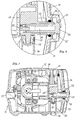
Fig.1 shows an exploded view of the components of the operating unit; -
Figs. 2 and3 show two views in perspective from opposite sides of the assembled unit; -
Fig.4 shows a view from above of the unit inFig. 2 ; -
Figs. 5 and 6 show two views from the front and side of the unit; -
Fig. 7 shows an enlarged view of a cross-section according to arrows A-A inFig. 5 ; -
Fig. 8 shows an enlarged detail ofFig. 7 in correspondence with the air inlet duct with filter; and -
Fig. 9 shows a variation of the operating unit where the body has a tool holder compartment. - As shown, the operating unit comprises fundamentally a
body 11 and apump group 12 enclosed in said body and designed to generate a flow of air under pressure. - The
body 11 is made up of two elements or shells, onebottom 13 and onetop 14, which superimpose and join on atransversal plane 15, at the level of their edges 13', 14' shaped to fit into each other, being self-centring. Thebottom shell 13 is equipped withbase legs 16. Internally bothshells pump group 12. The twoshells screws 18 inserted through the bottom shell and engaging corresponding holes provided, although not shown, in the top shell. The twoshells - The
pump group 12 has ahead 19, andelectric motor 20 and afan 21 for the motor joined to form a group that does not require ducts to be provided but only electric power connection for the motor. - The
head 19 of the pump group has anair inlet duct 22 and anoutlet duct 23. In theair inlet duct 22 is positioned, for example, apolymeric filter 24 or some other type of material, which is interchangeable from the outside. Thefilter 24 is fitted tightly in theinlet channel 22 and has alongitudinal cavity 24", the internal end of which is associated with a pin 22' which partially occupies the cross section as shown in the detail inFig. 8 , with the advantage that it reduces noise. - The
motor 20 is powered by means ofelectric cables 25, connected to asocket 26 and aswitch 27 and a safety fuse - not shown- assembled on aplate 28. Furthermore, the motor has two supporting flanges each with twoextensions 29 facing in opposite directions and which fit into corresponding seats 17 inside the twoshells - In the example illustrated, the
air inlet duct 22 protrudes from a lateral, vertical side of thehead 19 of the pump group, whereas theair outlet duct 23 extends from the top horizontal side ofsaid head 19, therefore at right angles to each other. - According to this arrangement, the mating edges 13', 14' of the two
shells body 11 have, on one of their parts. two recesses, forming together, when the body is closed, alateral seat 31 to receive theinlet duct 22 with interposition of aseal 32 and, in another of their parts, two slots to form, when the body is closed, alateral opening 33 to receive and hold the socket, the switch and the plate with fuse for connecting the motor to the electric power supply. At the same time, thetop shell 14 has a recess at the top with ahole 34 in the bottom to receive theair outlet duct 23, it also being fitted with aseal 35. - With the basic elements, that is to say the
body 11 and thepump group 12, configured in this way, assembly of the operating unit can be carried out automatically using mechanical means, fundamentally as a pack -Fig. 1 . This is carried out by positioning thegroup 12 in a first shell, placing the other shell on top of it so that, theair inlet duct 22 fits into itslateral seating 31, the socket and switch in thelateral opening 33 fits between the matching edges of the two shells and the air outle23 and relative seal inhole 34 at the top of the upper shell, and lastly by fixing the two shells together. - When the assembly has been effected, the
air inlet duct 22 housing thefilter 24 appears accessible on a side of the body -Figs. 2 and5 , thesocket 26 and theswitch 27 on another side of the body -Fig. 3 - and theair outlet duct 23 on the top of the body itself -Figs. 2 and3 - to insert an air delivery tube to the use facility.Filter 24 is, in this way, removable, operating from the outside of the body or shell by means of a tool to extract it through a slot 31' radially oriented to theseating 31 it is in. - Of particular importance -
Figs 1 and7 - is that inside thelower shell 13 of thebody 11, on an axis with a foot on thebase 16, there is aprotrusion 36 acting as a support for the bottom part of thehead 19 of thepump group 12. Theprotrusion 36 extends until it is up against the compressor or pump where it unites with a centring pin 19' with interposition of adamper element 37 and so as to be fundamentally in line and in front of theair outlet duct 23 in the top part -Fig. 7 . This feature enables absorption, without causing any adverse effects, of the force applied on theoutlet duct 23 when the air delivery tube to the use facility, is connected. - Differently from what has been described above, in a variation in the construction, where they are in right angle planes, the air input duct and output duct of the pump group can both be on the same horizontal plane and both be lodged between the matching edges of the shells forming the body when the latter is closed, or on a vertical plane and facing towards the top face of the body or shell, always and consequently with the possibility of automizable assembly of the group.
- In a further embodiment such as the one shown in
Fig. 9 , thebody 11 can be configured to form atool holder compartment 38 closed by acover 39, and theinlet 22 andoutlet 23 air ducts of the pump group can be placed side by side across a wall of said compartment so as to be accessed through the latter.
Claims (10)
- Operating unit to generate a flow of air under pressure in aerosol therapy appliances, comprising a pump group (12) which includes a head (19), an electric motor (20) and a fan (21), and a body enclosing said group and formed by a bottom shell and a top shell (13, 14) which are superimposed and close on a transversal plane on a level with their edges formed to self-centre one with the other, and where the head of the pump group has an air inlet duct (22) complete with filter (24) and an air outlet duct (23), and the motor is equipped with suspension elements in said body, characterised in that the motor (20) is electrically connected to a socket (26) and a switch (27) supported by a plate (28) wth a fuse, and that the shells forming said body have means for receiving and holding the air inlet duct (22) with filter (24), the air outlet duct (23) and the plate (28) with fuse, socket (26), and electric switch (27) following their overlapping for an automated assembly of the group.
- Operating unit according to claim 1, in which the air inlet duct (22) and the air outlet duct (23) of the pump group are in planes at right-angles to each other.
- Operating unit according to claims 1 and 2, in which the two shells (13,14) of the body have, on a level with their matching edges, two recesses forming together, when body is closed, a lateral lodging (31) to receive the air inlet duct (22) and the air filter, and two slots to form, with body closed, a lateral opening (33) to receive and hold the socket, switch and plate for connecting the motor to the electric supply source, and in which one of the two shells, the top one (14), has at the top a recess with a hole at the bottom (34) made to receive the air outlet duct (23).
- Operating unit according to claim 1, in which the air inlet duct (22) with filter (24) is lodged in the respective side seating (31) with interposition of a seal (32), and the air outlet duct is lodged in the respective hole (34) in the top of the body with interposition of a further seal (35).
- Operating unit according to any of the previous claims, in which the bottom shell (13) of said body is equipped with feet (16) at the bottom, and in which, inside said shell, on an axis with one of said feet, is shaped a protrusion (36) acting as a support for the head (19) of the pump group, said protrusion extending to rest against the bottom part of said head with interposition of a damper element (37) and so as to be in line and facing the air outlet duct (23).
- Operating unit according to the previous claims, in which the filter (24) is tightly fitted in the air inlet duct (22) and has a longitudinal cavity partially obstructed by a pin (22').
- Operating unit according to the previous claims, in which said filter can be removed from the outside of the body or shell, the filter being accessible using a tool to remove it through a slot (31') provided in said body or shell and radially oriented to the seating (31) hosting the air inlet duct.
- Operating unit according to claim 1, in which the air inlet duct (22) and the air outlet duct (23) of the pump group are parallel, both horizontal placed and held between the matching edges of the two shells forming said body
- Operating unit according to claim 8, in which the body forms a tool holder compartment (38) closed by a cover (39), and the air inlet and outlet ducts of the pump group are on a wall of said compartment and are accessible through the latter.
- An operating unit according to claim 1, in which the air inlet (22) and outlet (23) ducts of the pump group are parallel, both placed vertically and emerging on a level with the top of the top shell of said body.
Priority Applications (2)
| Application Number | Priority Date | Filing Date | Title |
|---|---|---|---|
| PL05734849T PL1743512T3 (en) | 2004-04-01 | 2005-03-24 | Automatised assembly operating unit in particular for aerosol appliances |
| SI200530821T SI1743512T1 (en) | 2004-04-01 | 2005-03-24 | A drive device for an automated assembly, in particular for aerosol devices |
Applications Claiming Priority (2)
| Application Number | Priority Date | Filing Date | Title |
|---|---|---|---|
| IT000020U ITBS20040020U1 (en) | 2004-04-01 | 2004-04-01 | AUTOMATED ASSEMBLY OPERATING UNIT PARTICULARLY FOR AEROSOLTERAPY EQUIPMENT |
| PCT/IT2005/000164 WO2005096685A1 (en) | 2004-04-01 | 2005-03-24 | Automatised assembly operating unit in particular for aerosol appliances |
Publications (2)
| Publication Number | Publication Date |
|---|---|
| EP1743512A1 EP1743512A1 (en) | 2007-01-17 |
| EP1743512B1 true EP1743512B1 (en) | 2009-07-29 |
Family
ID=34965598
Family Applications (1)
| Application Number | Title | Priority Date | Filing Date |
|---|---|---|---|
| EP05734849A Expired - Lifetime EP1743512B1 (en) | 2004-04-01 | 2005-03-24 | Automatised assembly operating unit in particular for aerosol appliances |
Country Status (10)
| Country | Link |
|---|---|
| US (1) | US7967576B2 (en) |
| EP (1) | EP1743512B1 (en) |
| CN (1) | CN1943289A (en) |
| AT (1) | ATE438289T1 (en) |
| DE (1) | DE602005015693D1 (en) |
| ES (1) | ES2330021T3 (en) |
| IT (1) | ITBS20040020U1 (en) |
| PL (1) | PL1743512T3 (en) |
| SI (1) | SI1743512T1 (en) |
| WO (1) | WO2005096685A1 (en) |
Families Citing this family (14)
| Publication number | Priority date | Publication date | Assignee | Title |
|---|---|---|---|---|
| ITVI20060119A1 (en) * | 2006-04-20 | 2007-10-21 | Massimiliano Azzi | VOLUMETRIC COMPRESSOR FOR MEDICAL USE WITH SIMPLIFIED MOUNTING AS WELL AS THE ASSEMBLY METHOD OF THE SAME. |
| US8931481B2 (en) * | 2009-06-04 | 2015-01-13 | Redmed Limited | Flow generator chassis assembly with suspension seal |
| CN201656765U (en) * | 2010-02-12 | 2010-11-24 | Emif科技有限公司 | EMI filter |
| US20110282248A1 (en) * | 2010-03-04 | 2011-11-17 | Martin Ruth E | Portable high frequency air pulse delivery device |
| JP5551050B2 (en) * | 2010-11-24 | 2014-07-16 | 株式会社マキタ | Air compressor |
| USD740930S1 (en) * | 2012-12-20 | 2015-10-13 | Koninklijke Philips N.V. | Nebulizer compressor |
| USD745137S1 (en) * | 2012-12-20 | 2015-12-08 | Koninklijke Philips N.V. | Nebulizer compressor |
| JP6480598B2 (en) | 2015-04-02 | 2019-03-13 | ヒル−ロム サービシーズ プライヴェート リミテッド | Respirator manifold |
| US10695522B2 (en) * | 2016-03-14 | 2020-06-30 | ResMed Pty Ltd | Respiratory pressure therapy device |
| USD859638S1 (en) * | 2017-12-22 | 2019-09-10 | Vectura Delivery Devices Limited | Nebulization device |
| USD1026166S1 (en) * | 2021-06-03 | 2024-05-07 | Hsin-Yung Lin | Hydrogen generator |
| USD1080859S1 (en) * | 2021-08-26 | 2025-06-24 | Shenzhen Gong Tao Technology Co., LTD. | Compressed atomizer |
| EP4283206B1 (en) | 2021-12-09 | 2025-08-06 | Guangdong Meizhi Precision-Manufacturing Co., Ltd. | Shell assembly, compressor, and air conditioner |
| US11779711B1 (en) * | 2022-09-02 | 2023-10-10 | Shenzhen Haige Cross-Border Technology Co., Ltd. | Atomizer with intelligent control digital display function |
Citations (3)
| Publication number | Priority date | Publication date | Assignee | Title |
|---|---|---|---|---|
| EP0519742A1 (en) * | 1991-06-21 | 1992-12-23 | Devilbiss Health Care, Inc. | Medical nebulizer control system |
| US5512077A (en) * | 1994-05-27 | 1996-04-30 | Owens-Brockway Glass Container Inc. | Test apparatus and testing method for a position sensor in a glassware forming machine |
| US6318360B1 (en) * | 1998-09-10 | 2001-11-20 | Medel S.P.A. | Single-unit apparatus for aerosol therapy with integrated compressor group and associated method of assembly |
Family Cites Families (18)
| Publication number | Priority date | Publication date | Assignee | Title |
|---|---|---|---|---|
| US4080103A (en) * | 1977-01-12 | 1978-03-21 | Bird F M | Portable air compressor system for respirator |
| US4389166A (en) * | 1979-10-22 | 1983-06-21 | Harvey-Westbury Corp. | Self-contained portable air compressor |
| US4331883A (en) * | 1979-10-29 | 1982-05-25 | Grenco S.P.A. | Portable power supply unit |
| EP0265545B1 (en) * | 1986-10-29 | 1991-03-06 | Brugger, Stephan, Dipl.-Wirt.-Ing. | Inhalation apparatus |
| EP0302958B1 (en) * | 1987-08-12 | 1992-05-20 | Brugger, Stephan, Dipl.-Wirt.-Ing. | Portable inhaler |
| USD348927S (en) * | 1991-10-03 | 1994-07-19 | Medel Italiana S.N.C. Di Giancarlo Attolini & C. | Portable inhalator |
| US20020005196A1 (en) * | 1994-11-15 | 2002-01-17 | Pari Gmbh Spezialisten Fur Effektive Inhalation | Portable inhalator compressor device |
| USD376199S (en) * | 1995-11-13 | 1996-12-03 | Thomas Industries Inc. | Cabinet for nebulizer |
| US6152134A (en) * | 1996-10-18 | 2000-11-28 | Invacare Corporation | Oxygen conserving device |
| DE19949633C2 (en) * | 1999-10-14 | 2003-04-10 | Map Medizin Technologie Gmbh | Device for supplying a breathing gas under positive pressure |
| IT1308581B1 (en) * | 1999-12-03 | 2002-01-08 | Medel Italiana Srl | APPARATUS FOR SPRAYING A LIQUID, IN PARTICULAR FOR MEDICAL USE. |
| MXPA02006777A (en) * | 2000-01-10 | 2004-04-05 | Thomas Industries Inc | Pump housing construction. |
| USD454393S1 (en) * | 2000-07-14 | 2002-03-12 | Resmed Limited | Flow generator |
| US20040047745A1 (en) * | 2002-09-06 | 2004-03-11 | Burkholder Robert F. | Air compressor assembly having enclosed unpainted air tank |
| US6926503B2 (en) * | 2002-09-27 | 2005-08-09 | Spx Corporation | Pump vibration reduction system |
| USD480093S1 (en) * | 2002-11-05 | 2003-09-30 | Pre Holding, Inc. | Combined portable compressor unit and battery |
| US7140845B2 (en) * | 2003-08-05 | 2006-11-28 | Eming Hsiao | Portable air compressor |
| CA2537077C (en) * | 2003-09-02 | 2010-12-07 | Airsep Corporation | Sound enclosure for portable oxygen concentrators |
-
2004
- 2004-04-01 IT IT000020U patent/ITBS20040020U1/en unknown
-
2005
- 2005-03-24 CN CNA2005800120271A patent/CN1943289A/en active Pending
- 2005-03-24 US US10/599,287 patent/US7967576B2/en not_active Expired - Fee Related
- 2005-03-24 ES ES05734849T patent/ES2330021T3/en not_active Expired - Lifetime
- 2005-03-24 DE DE602005015693T patent/DE602005015693D1/en not_active Expired - Lifetime
- 2005-03-24 AT AT05734849T patent/ATE438289T1/en active
- 2005-03-24 WO PCT/IT2005/000164 patent/WO2005096685A1/en not_active Ceased
- 2005-03-24 PL PL05734849T patent/PL1743512T3/en unknown
- 2005-03-24 EP EP05734849A patent/EP1743512B1/en not_active Expired - Lifetime
- 2005-03-24 SI SI200530821T patent/SI1743512T1/en unknown
Patent Citations (3)
| Publication number | Priority date | Publication date | Assignee | Title |
|---|---|---|---|---|
| EP0519742A1 (en) * | 1991-06-21 | 1992-12-23 | Devilbiss Health Care, Inc. | Medical nebulizer control system |
| US5512077A (en) * | 1994-05-27 | 1996-04-30 | Owens-Brockway Glass Container Inc. | Test apparatus and testing method for a position sensor in a glassware forming machine |
| US6318360B1 (en) * | 1998-09-10 | 2001-11-20 | Medel S.P.A. | Single-unit apparatus for aerosol therapy with integrated compressor group and associated method of assembly |
Also Published As
| Publication number | Publication date |
|---|---|
| CN1943289A (en) | 2007-04-04 |
| PL1743512T3 (en) | 2010-01-29 |
| US7967576B2 (en) | 2011-06-28 |
| DE602005015693D1 (en) | 2009-09-10 |
| SI1743512T1 (en) | 2010-01-29 |
| ES2330021T3 (en) | 2009-12-03 |
| EP1743512A1 (en) | 2007-01-17 |
| ITBS20040020U1 (en) | 2004-07-01 |
| ATE438289T1 (en) | 2009-08-15 |
| US20080190417A1 (en) | 2008-08-14 |
| WO2005096685A1 (en) | 2005-10-13 |
Similar Documents
| Publication | Publication Date | Title |
|---|---|---|
| US7967576B2 (en) | Automatised assembly operating unit in particular for aerosol appliances | |
| JP4977814B2 (en) | Front nose part of automobile with air circulation element | |
| US8302598B2 (en) | Breathing gas supply device | |
| KR101581198B1 (en) | Total heat exchange apparatus including bypass unit | |
| KR20130025649A (en) | Electric motor-driven compressor | |
| US8032977B2 (en) | Air moving device and method of making | |
| US6318360B1 (en) | Single-unit apparatus for aerosol therapy with integrated compressor group and associated method of assembly | |
| JP4181474B2 (en) | Spraying machine | |
| CN107990619A (en) | The setting structure and its method to set up of freezer compressor | |
| CN110856397A (en) | Electric control box components and air conditioners | |
| CN113091138B (en) | Vertical air conditioner and processing system of air duct structure of vertical air conditioner | |
| US8696146B2 (en) | Door mirror | |
| CN112605950B (en) | Electric tool shell and electric tool provided with same | |
| CN116937748B (en) | Outdoor energy storage device | |
| CN221430510U (en) | Air outlet device | |
| KR20130040282A (en) | Fan structure with rotor yoke and shaft for blower motor | |
| WO2007122578A1 (en) | Displacement compressor/aspirator for medical use with simplified assembly and assembly method | |
| PL1731339T3 (en) | Double fan ventilation assembly for vehicles | |
| CN213630731U (en) | A semiconductor dehumidifier | |
| CN114922800A (en) | Booster pump head, diaphragm booster pump and water treatment equipment | |
| CN212028116U (en) | Bladeless fan | |
| CN109855189B (en) | Portable air conditioner | |
| CN217696124U (en) | Liquid electric heating device | |
| JP3214253U (en) | Assembled storage | |
| EP2204297A2 (en) | Mounting system of an air conditioning equipment in a vehicle front dashboard |
Legal Events
| Date | Code | Title | Description |
|---|---|---|---|
| PUAI | Public reference made under article 153(3) epc to a published international application that has entered the european phase |
Free format text: ORIGINAL CODE: 0009012 |
|
| 17P | Request for examination filed |
Effective date: 20060925 |
|
| AK | Designated contracting states |
Kind code of ref document: A1 Designated state(s): AT BE BG CH CY CZ DE DK EE ES FI FR GB GR HU IE IS IT LI LT LU MC NL PL PT RO SE SI SK TR |
|
| DAX | Request for extension of the european patent (deleted) | ||
| TPAC | Observations filed by third parties |
Free format text: ORIGINAL CODE: EPIDOSNTIPA |
|
| GRAP | Despatch of communication of intention to grant a patent |
Free format text: ORIGINAL CODE: EPIDOSNIGR1 |
|
| RIN1 | Information on inventor provided before grant (corrected) |
Inventor name: ABATE, RICARDO Inventor name: ABATE, LUIGI |
|
| GRAS | Grant fee paid |
Free format text: ORIGINAL CODE: EPIDOSNIGR3 |
|
| GRAA | (expected) grant |
Free format text: ORIGINAL CODE: 0009210 |
|
| AK | Designated contracting states |
Kind code of ref document: B1 Designated state(s): AT BE BG CH CY CZ DE DK EE ES FI FR GB GR HU IE IS IT LI LT LU MC NL PL PT RO SE SI SK TR |
|
| REG | Reference to a national code |
Ref country code: GB Ref legal event code: FG4D |
|
| REG | Reference to a national code |
Ref country code: CH Ref legal event code: EP |
|
| REG | Reference to a national code |
Ref country code: IE Ref legal event code: FG4D |
|
| REF | Corresponds to: |
Ref document number: 602005015693 Country of ref document: DE Date of ref document: 20090910 Kind code of ref document: P |
|
| REG | Reference to a national code |
Ref country code: ES Ref legal event code: FG2A Ref document number: 2330021 Country of ref document: ES Kind code of ref document: T3 |
|
| NLV1 | Nl: lapsed or annulled due to failure to fulfill the requirements of art. 29p and 29m of the patents act | ||
| PG25 | Lapsed in a contracting state [announced via postgrant information from national office to epo] |
Ref country code: LT Free format text: LAPSE BECAUSE OF FAILURE TO SUBMIT A TRANSLATION OF THE DESCRIPTION OR TO PAY THE FEE WITHIN THE PRESCRIBED TIME-LIMIT Effective date: 20090729 Ref country code: SE Free format text: LAPSE BECAUSE OF FAILURE TO SUBMIT A TRANSLATION OF THE DESCRIPTION OR TO PAY THE FEE WITHIN THE PRESCRIBED TIME-LIMIT Effective date: 20090729 Ref country code: FI Free format text: LAPSE BECAUSE OF FAILURE TO SUBMIT A TRANSLATION OF THE DESCRIPTION OR TO PAY THE FEE WITHIN THE PRESCRIBED TIME-LIMIT Effective date: 20090729 Ref country code: IS Free format text: LAPSE BECAUSE OF FAILURE TO SUBMIT A TRANSLATION OF THE DESCRIPTION OR TO PAY THE FEE WITHIN THE PRESCRIBED TIME-LIMIT Effective date: 20091129 |
|
| REG | Reference to a national code |
Ref country code: PL Ref legal event code: T3 |
|
| PG25 | Lapsed in a contracting state [announced via postgrant information from national office to epo] |
Ref country code: NL Free format text: LAPSE BECAUSE OF FAILURE TO SUBMIT A TRANSLATION OF THE DESCRIPTION OR TO PAY THE FEE WITHIN THE PRESCRIBED TIME-LIMIT Effective date: 20090729 |
|
| PG25 | Lapsed in a contracting state [announced via postgrant information from national office to epo] |
Ref country code: BG Free format text: LAPSE BECAUSE OF FAILURE TO SUBMIT A TRANSLATION OF THE DESCRIPTION OR TO PAY THE FEE WITHIN THE PRESCRIBED TIME-LIMIT Effective date: 20091029 Ref country code: PT Free format text: LAPSE BECAUSE OF FAILURE TO SUBMIT A TRANSLATION OF THE DESCRIPTION OR TO PAY THE FEE WITHIN THE PRESCRIBED TIME-LIMIT Effective date: 20091129 |
|
| PG25 | Lapsed in a contracting state [announced via postgrant information from national office to epo] |
Ref country code: CZ Free format text: LAPSE BECAUSE OF FAILURE TO SUBMIT A TRANSLATION OF THE DESCRIPTION OR TO PAY THE FEE WITHIN THE PRESCRIBED TIME-LIMIT Effective date: 20090729 Ref country code: DK Free format text: LAPSE BECAUSE OF FAILURE TO SUBMIT A TRANSLATION OF THE DESCRIPTION OR TO PAY THE FEE WITHIN THE PRESCRIBED TIME-LIMIT Effective date: 20090729 Ref country code: RO Free format text: LAPSE BECAUSE OF FAILURE TO SUBMIT A TRANSLATION OF THE DESCRIPTION OR TO PAY THE FEE WITHIN THE PRESCRIBED TIME-LIMIT Effective date: 20090729 Ref country code: EE Free format text: LAPSE BECAUSE OF FAILURE TO SUBMIT A TRANSLATION OF THE DESCRIPTION OR TO PAY THE FEE WITHIN THE PRESCRIBED TIME-LIMIT Effective date: 20090729 |
|
| PLBI | Opposition filed |
Free format text: ORIGINAL CODE: 0009260 |
|
| PG25 | Lapsed in a contracting state [announced via postgrant information from national office to epo] |
Ref country code: SK Free format text: LAPSE BECAUSE OF FAILURE TO SUBMIT A TRANSLATION OF THE DESCRIPTION OR TO PAY THE FEE WITHIN THE PRESCRIBED TIME-LIMIT Effective date: 20090729 |
|
| PLAX | Notice of opposition and request to file observation + time limit sent |
Free format text: ORIGINAL CODE: EPIDOSNOBS2 |
|
| 26 | Opposition filed |
Opponent name: MEDEL GROUP SPA Effective date: 20100426 |
|
| PLAF | Information modified related to communication of a notice of opposition and request to file observations + time limit |
Free format text: ORIGINAL CODE: EPIDOSCOBS2 |
|
| PG25 | Lapsed in a contracting state [announced via postgrant information from national office to epo] |
Ref country code: MC Free format text: LAPSE BECAUSE OF NON-PAYMENT OF DUE FEES Effective date: 20100331 Ref country code: GR Free format text: LAPSE BECAUSE OF FAILURE TO SUBMIT A TRANSLATION OF THE DESCRIPTION OR TO PAY THE FEE WITHIN THE PRESCRIBED TIME-LIMIT Effective date: 20091030 |
|
| REG | Reference to a national code |
Ref country code: CH Ref legal event code: PL |
|
| PLBB | Reply of patent proprietor to notice(s) of opposition received |
Free format text: ORIGINAL CODE: EPIDOSNOBS3 |
|
| PG25 | Lapsed in a contracting state [announced via postgrant information from national office to epo] |
Ref country code: IE Free format text: LAPSE BECAUSE OF NON-PAYMENT OF DUE FEES Effective date: 20100324 |
|
| PG25 | Lapsed in a contracting state [announced via postgrant information from national office to epo] |
Ref country code: CH Free format text: LAPSE BECAUSE OF NON-PAYMENT OF DUE FEES Effective date: 20100331 Ref country code: LI Free format text: LAPSE BECAUSE OF NON-PAYMENT OF DUE FEES Effective date: 20100331 |
|
| PLBP | Opposition withdrawn |
Free format text: ORIGINAL CODE: 0009264 |
|
| PLBD | Termination of opposition procedure: decision despatched |
Free format text: ORIGINAL CODE: EPIDOSNOPC1 |
|
| PLBM | Termination of opposition procedure: date of legal effect published |
Free format text: ORIGINAL CODE: 0009276 |
|
| STAA | Information on the status of an ep patent application or granted ep patent |
Free format text: STATUS: OPPOSITION PROCEDURE CLOSED |
|
| 27C | Opposition proceedings terminated |
Effective date: 20111103 |
|
| PG25 | Lapsed in a contracting state [announced via postgrant information from national office to epo] |
Ref country code: CY Free format text: LAPSE BECAUSE OF FAILURE TO SUBMIT A TRANSLATION OF THE DESCRIPTION OR TO PAY THE FEE WITHIN THE PRESCRIBED TIME-LIMIT Effective date: 20090729 |
|
| PG25 | Lapsed in a contracting state [announced via postgrant information from national office to epo] |
Ref country code: LU Free format text: LAPSE BECAUSE OF NON-PAYMENT OF DUE FEES Effective date: 20100324 Ref country code: HU Free format text: LAPSE BECAUSE OF FAILURE TO SUBMIT A TRANSLATION OF THE DESCRIPTION OR TO PAY THE FEE WITHIN THE PRESCRIBED TIME-LIMIT Effective date: 20100130 |
|
| PG25 | Lapsed in a contracting state [announced via postgrant information from national office to epo] |
Ref country code: TR Free format text: LAPSE BECAUSE OF FAILURE TO SUBMIT A TRANSLATION OF THE DESCRIPTION OR TO PAY THE FEE WITHIN THE PRESCRIBED TIME-LIMIT Effective date: 20090729 |
|
| REG | Reference to a national code |
Ref country code: FR Ref legal event code: PLFP Year of fee payment: 12 |
|
| REG | Reference to a national code |
Ref country code: FR Ref legal event code: PLFP Year of fee payment: 13 |
|
| PGFP | Annual fee paid to national office [announced via postgrant information from national office to epo] |
Ref country code: FR Payment date: 20170222 Year of fee payment: 13 |
|
| PGFP | Annual fee paid to national office [announced via postgrant information from national office to epo] |
Ref country code: AT Payment date: 20170223 Year of fee payment: 13 Ref country code: GB Payment date: 20170223 Year of fee payment: 13 |
|
| PGFP | Annual fee paid to national office [announced via postgrant information from national office to epo] |
Ref country code: SI Payment date: 20180301 Year of fee payment: 14 |
|
| REG | Reference to a national code |
Ref country code: AT Ref legal event code: MM01 Ref document number: 438289 Country of ref document: AT Kind code of ref document: T Effective date: 20180324 |
|
| GBPC | Gb: european patent ceased through non-payment of renewal fee |
Effective date: 20180324 |
|
| PG25 | Lapsed in a contracting state [announced via postgrant information from national office to epo] |
Ref country code: AT Free format text: LAPSE BECAUSE OF NON-PAYMENT OF DUE FEES Effective date: 20180324 |
|
| PG25 | Lapsed in a contracting state [announced via postgrant information from national office to epo] |
Ref country code: GB Free format text: LAPSE BECAUSE OF NON-PAYMENT OF DUE FEES Effective date: 20180324 |
|
| PG25 | Lapsed in a contracting state [announced via postgrant information from national office to epo] |
Ref country code: FR Free format text: LAPSE BECAUSE OF NON-PAYMENT OF DUE FEES Effective date: 20180331 |
|
| REG | Reference to a national code |
Ref country code: SI Ref legal event code: KO00 Effective date: 20191111 |
|
| PG25 | Lapsed in a contracting state [announced via postgrant information from national office to epo] |
Ref country code: SI Free format text: LAPSE BECAUSE OF NON-PAYMENT OF DUE FEES Effective date: 20190325 |
|
| PGFP | Annual fee paid to national office [announced via postgrant information from national office to epo] |
Ref country code: DE Payment date: 20200214 Year of fee payment: 16 Ref country code: PL Payment date: 20200217 Year of fee payment: 16 Ref country code: IT Payment date: 20200323 Year of fee payment: 16 |
|
| PGFP | Annual fee paid to national office [announced via postgrant information from national office to epo] |
Ref country code: BE Payment date: 20200218 Year of fee payment: 16 |
|
| PGFP | Annual fee paid to national office [announced via postgrant information from national office to epo] |
Ref country code: ES Payment date: 20200401 Year of fee payment: 16 |
|
| REG | Reference to a national code |
Ref country code: DE Ref legal event code: R119 Ref document number: 602005015693 Country of ref document: DE |
|
| REG | Reference to a national code |
Ref country code: BE Ref legal event code: MM Effective date: 20210331 |
|
| PG25 | Lapsed in a contracting state [announced via postgrant information from national office to epo] |
Ref country code: DE Free format text: LAPSE BECAUSE OF NON-PAYMENT OF DUE FEES Effective date: 20211001 |
|
| PG25 | Lapsed in a contracting state [announced via postgrant information from national office to epo] |
Ref country code: IT Free format text: LAPSE BECAUSE OF NON-PAYMENT OF DUE FEES Effective date: 20210324 |
|
| REG | Reference to a national code |
Ref country code: ES Ref legal event code: FD2A Effective date: 20220523 |
|
| PG25 | Lapsed in a contracting state [announced via postgrant information from national office to epo] |
Ref country code: ES Free format text: LAPSE BECAUSE OF NON-PAYMENT OF DUE FEES Effective date: 20210325 Ref country code: BE Free format text: LAPSE BECAUSE OF NON-PAYMENT OF DUE FEES Effective date: 20210331 |
|
| PG25 | Lapsed in a contracting state [announced via postgrant information from national office to epo] |
Ref country code: PL Free format text: LAPSE BECAUSE OF NON-PAYMENT OF DUE FEES Effective date: 20210324 |