EP1742015A2 - Arrangement for in-situ component monitoring - Google Patents
Arrangement for in-situ component monitoring Download PDFInfo
- Publication number
- EP1742015A2 EP1742015A2 EP06252997A EP06252997A EP1742015A2 EP 1742015 A2 EP1742015 A2 EP 1742015A2 EP 06252997 A EP06252997 A EP 06252997A EP 06252997 A EP06252997 A EP 06252997A EP 1742015 A2 EP1742015 A2 EP 1742015A2
- Authority
- EP
- European Patent Office
- Prior art keywords
- component
- camera
- arrangement
- image
- target portion
- Prior art date
- Legal status (The legal status is an assumption and is not a legal conclusion. Google has not performed a legal analysis and makes no representation as to the accuracy of the status listed.)
- Granted
Links
Images


Classifications
-
- G—PHYSICS
- G01—MEASURING; TESTING
- G01B—MEASURING LENGTH, THICKNESS OR SIMILAR LINEAR DIMENSIONS; MEASURING ANGLES; MEASURING AREAS; MEASURING IRREGULARITIES OF SURFACES OR CONTOURS
- G01B11/00—Measuring arrangements characterised by the use of optical techniques
- G01B11/16—Measuring arrangements characterised by the use of optical techniques for measuring the deformation in a solid, e.g. optical strain gauge
-
- G—PHYSICS
- G01—MEASURING; TESTING
- G01B—MEASURING LENGTH, THICKNESS OR SIMILAR LINEAR DIMENSIONS; MEASURING ANGLES; MEASURING AREAS; MEASURING IRREGULARITIES OF SURFACES OR CONTOURS
- G01B11/00—Measuring arrangements characterised by the use of optical techniques
- G01B11/24—Measuring arrangements characterised by the use of optical techniques for measuring contours or curvatures
Definitions
- the present invention relates to in situ component monitoring and more particularly to monitoring of blades and turbines within a gas turbine engine.
- monitoring of components such as blades within a gas turbine engine is necessary both during initial design and prototyping of an engine as well as ongoing monitoring of engine performance in service.
- rotating components such as turbine blades there is distortion of those blades under load and it is desirable to monitor such distortion for acceptability and safety purposes.
- an in situ component monitoring arrangement for a gas turbine engine comprising a camera and light source, the light source providing in use illumination of the component as it rotates and the camera arranged to receive, in use an image from the component, a controller comparing images of the component to monitor variation in the component, the arrangement characterised in that the camera is arranged to rotate with the component in use and obtain images of at least a target portion of the component to allow comparison by the controller of the images received to determine variation in the component.
- the light source may be arranged to rotate with the component.
- the target portion is enhanced by the camera in the image obtained.
- Such enhanced spatial identification is possibly provided by reflective target features in the target portions.
- the target portion is rendered more specifically identifiable by portions of a recognisable grid in the target portion.
- the camera is coupled to the controller by a wireless connection.
- the wireless connection may be an optical beam coupling.
- the camera is coupled to the controller by a rotatable coupling.
- the camera and the controller are co-mounted to rotate with each other and the controller incorporates storage means to store images for subsequent comparison.
- the camera and the component rotate at substantially the same speed so effectively the images obtained are of an equivalent target portion of the component.
- the arrangement incorporates more than one camera and target portion for different parts of the component.
- the arrangement incorporates more than one camera and each camera monitors a variation in a discrete and different direction on the component to the other camera.
- the, or each, camera comprises an axis which is arranged coincident with a rotational axis of the component.
- a mirror is arranged to reflect the image from the target portion of the component into the camera, and the mirror is arranged to rotate about the axis of the component.
- the controller is arranged to compare a reference image of the target area when the component is stationary with a current image of the target area in order to determine variation.
- that variation is distortion.
- the component is a rotor blade of a gas turbine engine and the camera is mounted within a spinner fairing of the gas turbine engine.
- the window may distort the image received and there may be problems with actual provision of a window and a need to re-configure for different target parts of the component to be monitored.
- the present in situ component monitoring arrangement is particularly directed towards components which rotate and are subject to distortion as a result of rotational loads placed upon that component.
- a typical example of a rotating component is a turbine blade assembly in a gas turbine engine.
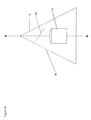
- FIG. 1 provides a rudimentary schematic illustration of an in situ component monitoring arrangement in accordance with the present invention as a part cross section.
- the arrangement 1 has a camera 2 mounted in a mounting 3, to which a rotating component in the form of a turbine blade 4 are secured.
- An aerodynamic covering 5 is provided to the mounting 3 for the blades 4.
- the camera 2 is arranged to receive an image from a target portion of the rotating component 4. In Figure 1 this is substantially one side 6 of the rotating component 4. In such circumstances distortions and other alterations in the shape of the blade 4 may be viewed by the camera 2 in the image taken and schematically illustrated by dot lines 7.
- markings 8 In order to emphasise position within the image 7 taken by the camera 2 normally identifiable markings 8 as noticeable targets will be placed on the surface 6. Markings can be dots, stripes, crosses or such like. The markings 8 will generally be regular in distribution but it will be understood it is alterations in these marking positions as a result of distortion that are of importance. Thus, the images received by the camera 2 at different stages of the rotational operation will be compared so that there is like for like comparisons of the markings 8 in the two images for comparison, thus whether there is a regular distribution of target markings or not is of limited importance.
- the markings 8 can simply take the form of reflective patches or dots or distinct features such as triangles or other shapes or patterns on or attached to the rotating component.
- this light source 9 will also be arranged to rotate with the camera 2 on the mounting 3.
- other forms of illumination of the surface 6 may be used provided there is highlighting of the markings 8 or to render the component appropriately illuminated as a target portion for image comparison.
- the present arrangement 1 comprises the camera 2 and the light source 9 in order that the camera 2 can obtain images of the surface 6 of the component 4. These images are then utilised to determine distortion of the component 4 under load as it rotates. In such circumstances it is necessary to either provide a wireless link or a slip ring coupling or other data transfer mechanism to allow transmission of those images to an appropriate controller.
- an image storage device could be provided within the mounting and this retained until after testing when the images will then be retrieved for analysis.
- some form of wireless image transmission to a remote controller and processing device will be utilised in order to allow real time monitoring of the component.
- a normal monitoring episode will include use of the camera 2 to determining an image of the stationary component 4 and this image then relayed to a storage device as a reference image. Once the rotating component 4 rotates as indicated stresses and strains and other loads are presented to the component 4 which will cause distortion and displacement of the component 4. These distortions and displacements of the blade are then viewed by the camera 2 and different current in use images obtained. Again these differ in use as images at different rotation speeds and other loadings of the component 4 are relayed by the camera 2 to a remote controller and processor device. The images are compared in order to identify and compare the distortions and displacements in the rotating equipment.
- Figure 1b shows a preferable arrangement with the camera 2 and mirror 2a on the rotation centre line x-x.
- the component being monitored is a fan blade 4 and the camera 2 is housed in a spinner fairing 5 (aerodynamic covering).
- the camera 2 is mounted so that its centre axis is coaxial with that of the rotational axis of the spinner fairing 5, thereby reducing centrifugal forces on the camera and/or its mountings.
- a mirror 2a is positioned to reflect images of the fan blade 4 into the camera 2 via a window or aperture 3a included in the aerodynamic covering 5.
- the mirror 2a is arranged to rotate about its own central axis coincident with the axis of the component (4).
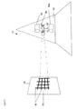
- a separate calibration device is generally used for determining the exact values of displacements in a component such as a blade assembly for a gas turbine engine.
- This calibration device is illustrated in Figure 2.
- the camera 2 is mounted in a mounting 3 but a calibration tool 10 is utilised to calibrate the image received by the camera 2.
- a calibration tool 10 which is accurately incremented with noticeable axial markers 11 and radial calibration spokes 12 it will be possible to calibrate the actual image received by the camera 2 in terms of axial, radial and circumferential co-ordinate position for the whole volume of the blade mounted in the mounting 3.
- the initial stationary image can be accurately quantified and then variations in the different images produced as the blade is distorted and displaced with rotational load can be simply compared to the calibrated image reference frame, provided by images of the tool 10.
- the camera 2 By allowing the camera 2 to rotate with the component it will be understood a consistent image of a particular target portion of the blade or component is achieved. Such arrangements remove the requirement for high brightness pulsed lasers and providing a viewing aperture or window in the casing so that the camera can view a rotating component. It will be understood that as the camera 2 is essentially moving with the target area from which an image is taken. Thus, with limited time delay and shift between the image reflection and receipt of the image by camera 2 it is possible to use a relative slow camera exposure time and consequentially high spatial resolution of the image. Essentially the camera is substantially viewing the same part of the component surface in a fixed rotational relationship. The cameras may be subject to vibration but as there will be relatively slow variation in displacement and distortion effects on the component, it will be possible to use relatively long exposure times to acquire an image in comparison.
- the component 4 can be viewed along its whole length simultaneously with markings 8 or otherwise in order to provide fixed references within the whole component 4 for comparison between the images received.
- FIGS 3 and 4 respectively illustrate profiling of a tube or pipe utilising a triangulation technique.
- a camera 22 is mounted in a mounting 23, which is generally of an aerodynamic nature.
- the mounting 23 also incorporates light sources 29a and 29b, which project respective beams of light towards the surface 24 of a tube or pipe within which the rotating mounting 23 is positioned. These beams coincide at a position A and an image is acquired by the camera 22. In such circumstances movement of the surface 24 in the direction of either arrowhead B or arrowhead C will result in displacement of the co-incident spots for the beams from the light sources 29a and 29b.
- Figure 4 illustrates three different incident spot positions for the light beams projected by the light sources 29 in Figure 3.
- the light beams could also provide lines of illumination but for example the situation with spots is described below.
- the image received by the camera 22 is substantially of the spots 20a and 21a which are close together and therefore are consistent with the calibrated distance where the beams from the light sources 29 should coincide.
- Displacement in the direction of arrowhead B or arrowhead C causes the displacement of the spots from each other in the image viewed by the camera.
- Figures 4d to 4f may be created by incident line projection on a component.
- Figure 4d is equivalent to Figure 4b above.
- the distance between the lines on figure 4d gives the radial displacement of A in Figure 3.
- a waviness in the lines as denoted in Figure 4f gives an indication of the radial variations at particular circumferential locations during a rotational episode.
- the depiction in Figure 4f showing wavy lines gives an indication of the shape of the casing as shown by the dashed line 24' in Figure 3.
- distortion of the casing gives non-straight (wavy) lines in the image.
- Figure 4e is an equivalent of 4a above.
- the spots and lines can be made individually distinct in their appearance so that no ambiguity will exist in the radial motion perceived.
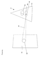
- Figure 5 describes an in situ monitoring arrangement 50 in accordance with the present invention in which distortion in a wall surface 54 is determined by viewing differences in the image received by a camera 52 of a projected grid or matrix 50 projected onto the wall or surface 54 by a light projection system 59 comprising a light source 70, a lens 71 and a grid/matrix 72.
- a light projection system 59 comprising a light source 70, a lens 71 and a grid/matrix 72.
- the camera 52 and light projection system 59 are mounted in a mounting 53, which generally rotates such that the camera uses the same grid 50 projected by the projected system 59. It is understood if this system 59 is rotated then generally the mounting 53 will rotate at the same speed as the surface 54 rotation such that the subject target area of the surface 54 is therefore consistent.
- the wall/surface 54 may be stationary and the mounting 53 rotated in order that the grid is therefore projected upon different parts of wall 54.
- data points 58 are compared in the images received by the camera 52 in order to determine circumferential and axial movements of the surface 54.
- the surface wall 54 may be coated with a reflective material to improve the return light signal.
- the grid pattern does not need to be a rectilinear design, but may be any recognisable or structured light pattern.
- a regular pattern could be viewed with a Moiré type filter to enhance distortion information.
- the arrangement within the aerodynamic covering 5 could for example comprise a shearography or interferometry system to perform distortion measurement on the wall 24.
- Figure 6 illustrates means of determining distance from an annulus utilising an astigmatic projection system.
- the arrangement 61 has a camera 62 and a light source 69 mounted within a mounting 63 such that the mounting 63 rotates with both the camera 62 and the light source 69.
- the light source 69 incorporates a lens system in order to project a beam 60 towards a surface 64 such that the incident pattern 68 on the surface 64 varies dependent on distance. This variation in the incident pattern 68 on the surface 64 is achieved through the lens mechanism 66, which forms part of the light source 69.
- Figure 6a correct or calibrated distance is achieved by creation of a perfectly round pattern 68 on the surface 64. This pattern will be observed as an image by the camera 62 and therefore distance determined.
- the surface 64 is too near to the mounting 63 or annulus.
- the pattern 68b is oval and lateral as a result of the lens mechanism 66 in the light source 69. Again this pattern 68b is viewed, as an image by the camera 62. The extent of the oval shape in the pattern 68b can be compared with calibrated values in order to determine the distance between the annular position of the mounting 63 and the surface 64.
- the surface 64 is further than the calibrated value from the annulus of the mounting 63 so that the incident pattern 68c is now again oval but in a vertical orientation.
- This pattern 68c is again viewed and received as an image by camera 62 in order to determine the distance from the mounting 63.
- the arrangement may be initially calibrated by determination of the pattern 68 in terms of how round its shape, that is to say its distortion to an oval and whether that oval in lateral or vertical or inclined in order to provide a set of reference images.
- the actual distance can be determined with some accuracy by comparison of the test camera image with the reference images.
- the images from the camera will be transferred to an appropriate controller device in order to facilitate the comparison described above.
- visible light is the preferred electromagnetic waveband of use as described herein, the utilisation of infrared or microwave bands may be preferable for some or all of the above devices, dependant on their appropriate efficacy in any given environment.
Abstract
Description
- The present invention relates to in situ component monitoring and more particularly to monitoring of blades and turbines within a gas turbine engine.
- It will be understood that monitoring of components such as blades within a gas turbine engine is necessary both during initial design and prototyping of an engine as well as ongoing monitoring of engine performance in service. With regard to rotating components such as turbine blades there is distortion of those blades under load and it is desirable to monitor such distortion for acceptability and safety purposes.
- An example of a previous monitoring arrangement is described in
US Patent No. 4616932 . Thus it can be seen typically an aperture or window is provided in order to gain visual access to monitor the component in this case a blade. A casing window is inserted and a pulsed laser of high brightness is used in order to gain sufficient reflectivity for observation. Nevertheless, such high brightness lasers are unreliable and can present a significant hazard. The necessity of providing a window as well as a laser and its potential hazards along with unreliability creates limitations with regard to in situ testing of a gas turbine engines by these previous methods. Furthermore, it may be necessary to vary the incident height of the laser beam on the component which in turn requires considerable time and effort with regard to reconfiguring and setting blade heights and limits the possibilities with respect to simultaneous extraction of data at different heights on the blade or rotating component. A further disadvantage with projection of laser beam over a large distance is that it can be deviated. - It will be appreciated viewing a component such as a rotating blade through a casing window also has its limitations with respect of a distortion of the image viewed and so the amount of valuable component shape data extracted. It will be appreciated that current monitoring methods require an up stream laser and this itself can compromise the accuracy of the air flow loading on the blade.
- There are potential problems and limitations upon convenient use of these prior monitoring arrangements in situations other than with ground based running of an engine. Finally, current monitoring methods limit blade shape determination toward one particular engine configuration.
- In accordance with the present invention there is provided an in situ component monitoring arrangement for a gas turbine engine, the arrangement comprising a camera and light source, the light source providing in use illumination of the component as it rotates and the camera arranged to receive, in use an image from the component, a controller comparing images of the component to monitor variation in the component, the arrangement characterised in that the camera is arranged to rotate with the component in use and obtain images of at least a target portion of the component to allow comparison by the controller of the images received to determine variation in the component.
- The light source may be arranged to rotate with the component.
- Generally, the target portion is enhanced by the camera in the image obtained.
- Such enhanced spatial identification is possibly provided by reflective target features in the target portions.
- Alternatively, the target portion is rendered more specifically identifiable by portions of a recognisable grid in the target portion.
- Typically the camera is coupled to the controller by a wireless connection.
- Possibly the wireless connection may be an optical beam coupling.
- Alternatively, the camera is coupled to the controller by a rotatable coupling.
- Further alternatively, the camera and the controller are co-mounted to rotate with each other and the controller incorporates storage means to store images for subsequent comparison.
- Typically, the camera and the component rotate at substantially the same speed so effectively the images obtained are of an equivalent target portion of the component.
- Possibly, the arrangement incorporates more than one camera and target portion for different parts of the component.
- Alternatively, the arrangement incorporates more than one camera and each camera monitors a variation in a discrete and different direction on the component to the other camera.
- Preferably, the, or each, camera comprises an axis which is arranged coincident with a rotational axis of the component.
- Alternatively, a mirror is arranged to reflect the image from the target portion of the component into the camera, and the mirror is arranged to rotate about the axis of the component.
- Generally the controller is arranged to compare a reference image of the target area when the component is stationary with a current image of the target area in order to determine variation. Generally, that variation is distortion.
- Preferably, the component is a rotor blade of a gas turbine engine and the camera is mounted within a spinner fairing of the gas turbine engine.
- Embodiments of the present invention will be now described by way of example with reference to the accompanying drawings in which:-
- Figure 1 is a schematic cross-section depicting the configuration of an in situ component monitoring arrangement in accordance with the present invention;
- Figure 1b is a schematic cross-section depicting an alternative configuration of an in situ component monitoring arrangement in accordance with the present invention;
- Figure 2 illustrates means for in situ calibration of the arrangement depicted in Figure 1;
- Figure 3 provides a schematic illustration utilising a triangulation type regime to determine tube or wall profiling;
- Figure 4 illustrates schematically the images possible with respect to the triangulation configuration used for tube or wall profiling depicted in Figure 3;
- Figure 5 provides a schematic illustration of a wall distortion in situ monitoring arrangements in accordance with the present invention; and,
- Figure 6 illustrates an in situ monitoring arrangement in accordance with the present invention to determine distance to an annulus utilising an astigmatic system of image projection.
- As indicated above there are potential problems with previous systems which utilise cameras which view a component through a window. The window may distort the image received and there may be problems with actual provision of a window and a need to re-configure for different target parts of the component to be monitored.
- The present in situ component monitoring arrangement is particularly directed towards components which rotate and are subject to distortion as a result of rotational loads placed upon that component. A typical example of a rotating component is a turbine blade assembly in a gas turbine engine. By combining a camera to monitor the component with that rotating component it will be appreciated that the image viewed by the camera is substantially of the same blade target portion as the combination rotates. There may be problems with respect to vibration but these can be generally minimised and image judder corrected.
- Figure 1 provides a rudimentary schematic illustration of an in situ component monitoring arrangement in accordance with the present invention as a part cross section. Thus, the
arrangement 1 has acamera 2 mounted in amounting 3, to which a rotating component in the form of a turbine blade 4 are secured. Anaerodynamic covering 5 is provided to themounting 3 for the blades 4. It will be understand that the camera and the blades 4 rotate with themounting 3 generally on an axis x - x so the blades 4 are subject to load distortions. It will be understood that generally a number of blades 4 will be mounted in themounting 3. Thecamera 2 is arranged to receive an image from a target portion of the rotating component 4. In Figure 1 this is substantially one side 6 of the rotating component 4. In such circumstances distortions and other alterations in the shape of the blade 4 may be viewed by thecamera 2 in the image taken and schematically illustrated bydot lines 7. - In order to emphasise position within the
image 7 taken by thecamera 2 normallyidentifiable markings 8 as noticeable targets will be placed on the surface 6. Markings can be dots, stripes, crosses or such like. Themarkings 8 will generally be regular in distribution but it will be understood it is alterations in these marking positions as a result of distortion that are of importance. Thus, the images received by thecamera 2 at different stages of the rotational operation will be compared so that there is like for like comparisons of themarkings 8 in the two images for comparison, thus whether there is a regular distribution of target markings or not is of limited importance. Themarkings 8 can simply take the form of reflective patches or dots or distinct features such as triangles or other shapes or patterns on or attached to the rotating component. - It will be understood in order to enhance definition and clarity of the image normally a high intensity light source will be used. Generally, this
light source 9 will also be arranged to rotate with thecamera 2 on themounting 3. However, it will also be understood that other forms of illumination of the surface 6 may be used provided there is highlighting of themarkings 8 or to render the component appropriately illuminated as a target portion for image comparison. - In view of the above it will be the appreciated that the
present arrangement 1 comprises thecamera 2 and thelight source 9 in order that thecamera 2 can obtain images of the surface 6 of the component 4. These images are then utilised to determine distortion of the component 4 under load as it rotates. In such circumstances it is necessary to either provide a wireless link or a slip ring coupling or other data transfer mechanism to allow transmission of those images to an appropriate controller. Alternatively, an image storage device could be provided within the mounting and this retained until after testing when the images will then be retrieved for analysis. However, more normally as indicated some form of wireless image transmission to a remote controller and processing device will be utilised in order to allow real time monitoring of the component. - A normal monitoring episode will include use of the
camera 2 to determining an image of the stationary component 4 and this image then relayed to a storage device as a reference image. Once the rotating component 4 rotates as indicated stresses and strains and other loads are presented to the component 4 which will cause distortion and displacement of the component 4. These distortions and displacements of the blade are then viewed by thecamera 2 and different current in use images obtained. Again these differ in use as images at different rotation speeds and other loadings of the component 4 are relayed by thecamera 2 to a remote controller and processor device. The images are compared in order to identify and compare the distortions and displacements in the rotating equipment. - Figure 1b shows a preferable arrangement with the
camera 2 andmirror 2a on the rotation centre line x-x. Where the present invention is used in a gas turbine engine, the component being monitored is a fan blade 4 and thecamera 2 is housed in a spinner fairing 5 (aerodynamic covering). Thecamera 2 is mounted so that its centre axis is coaxial with that of the rotational axis of thespinner fairing 5, thereby reducing centrifugal forces on the camera and/or its mountings. Amirror 2a is positioned to reflect images of the fan blade 4 into thecamera 2 via a window oraperture 3a included in theaerodynamic covering 5. Preferably, themirror 2a is arranged to rotate about its own central axis coincident with the axis of the component (4). - For determining the exact values of displacements in a component such as a blade assembly for a gas turbine engine a separate calibration device is generally used. This calibration device is illustrated in Figure 2. As previously the
camera 2 is mounted in a mounting 3 but acalibration tool 10 is utilised to calibrate the image received by thecamera 2. It will be understood there will be a number of parallax and other optical effects upon the image received by thecamera 2 so that providing acalibration tool 10 which is accurately incremented with noticeableaxial markers 11 andradial calibration spokes 12 it will be possible to calibrate the actual image received by thecamera 2 in terms of axial, radial and circumferential co-ordinate position for the whole volume of the blade mounted in the mounting 3. In such circumstances the initial stationary image can be accurately quantified and then variations in the different images produced as the blade is distorted and displaced with rotational load can be simply compared to the calibrated image reference frame, provided by images of thetool 10. - By allowing the
camera 2 to rotate with the component it will be understood a consistent image of a particular target portion of the blade or component is achieved. Such arrangements remove the requirement for high brightness pulsed lasers and providing a viewing aperture or window in the casing so that the camera can view a rotating component. It will be understood that as thecamera 2 is essentially moving with the target area from which an image is taken. Thus, with limited time delay and shift between the image reflection and receipt of the image bycamera 2 it is possible to use a relative slow camera exposure time and consequentially high spatial resolution of the image. Essentially the camera is substantially viewing the same part of the component surface in a fixed rotational relationship. The cameras may be subject to vibration but as there will be relatively slow variation in displacement and distortion effects on the component, it will be possible to use relatively long exposure times to acquire an image in comparison. - By rotating the
camera 2 with the component 4 it is possible to minimise the time required to acquire a whole component shape data set. The component 4 can be viewed along its whole length simultaneously withmarkings 8 or otherwise in order to provide fixed references within the whole component 4 for comparison between the images received. - As indicated above generally a like for like image comparison will be performed in accordance with an in situ monitoring arrangement in accordance with the present invention. Thus axial, radial and circumferential movements of optically
markings 8 between the images will be compared and contrasted in order to denote distortions either globally over the whole component 4 or localised variations. It must be appreciated that a component may bow or twist or be otherwise distorted or displaced in terms of dimensions for rotational loads. - As will be described later with regard to association of the present arrangement with a controller a number of images can be compared with the stationary reference or earlier images in order to allow analysis of the component under rotational load.
- Alternative refinements of the present in situ monitoring arrangement are described below with regard to Figures 3 - 6. These alternatives relate respectively to utilisation of the arrangement for profiling of a tube or pipe, determination of wall distortion and determination of distance to an annulus.
- Referring to Figures 3 and 4, which respectively illustrate profiling of a tube or pipe utilising a triangulation technique. As previously a
camera 22 is mounted in a mounting 23, which is generally of an aerodynamic nature. The mounting 23 also incorporateslight sources surface 24 of a tube or pipe within which the rotating mounting 23 is positioned. These beams coincide at a position A and an image is acquired by thecamera 22. In such circumstances movement of thesurface 24 in the direction of either arrowhead B or arrowhead C will result in displacement of the co-incident spots for the beams from thelight sources camera 22 and therefore can be utilised in order to determine the profile of thetube 24. If the mounting 23 is fixed then profiling of a particular circumference of thesurface 24 will be achieved. If the mounting 23 is arranged to progress and move along the tube or pipe from one end to the other then the whole, or part, of thesurface 24 from one end to the other of the pipe can be profiled in terms of displacements of thesurface 24 in the direction of arrowheads B, C. - Figure 4 illustrates three different incident spot positions for the light beams projected by the light sources 29 in Figure 3. The light beams could also provide lines of illumination but for example the situation with spots is described below. Thus, in Figure 4a it will be noted that the image received by the
camera 22 is substantially of thespots beams spots broken line 25 in Figure 4b. If there is displacement in the direction of arrowhead C there is foreshortening of incidence of the beams 30 upon thesurface 24 such that thespots notional coincidence position 25 but in these circumstances rather than crossing over the beams 30 have become incident upon thesurface 24 prior to such crossover so thespots light sources - As indicated above rather than incident spots it is possible for the light beams to project lines incident upon a component. Thus Figures 4d to 4f may be created by incident line projection on a component. Figure 4d is equivalent to Figure 4b above. The distance between the lines on figure 4d gives the radial displacement of A in Figure 3. A waviness in the lines as denoted in Figure 4f gives an indication of the radial variations at particular circumferential locations during a rotational episode. In such circumstances, it will be appreciated that the depiction in Figure 4f showing wavy lines gives an indication of the shape of the casing as shown by the dashed line 24' in Figure 3. Thus it will be appreciated that distortion of the casing gives non-straight (wavy) lines in the image. Figure 4e is an equivalent of 4a above. The spots and lines can be made individually distinct in their appearance so that no ambiguity will exist in the radial motion perceived.
- These variations in the displacement of the
spots 20, 21 c are utilised and observed in theimage camera 22 to calculate wall displacement and therefore allow profiling of thesurface 24 either through operational episodes or structural determination. - Figure 5 describes an in
situ monitoring arrangement 50 in accordance with the present invention in which distortion in awall surface 54 is determined by viewing differences in the image received by acamera 52 of a projected grid ormatrix 50 projected onto the wall orsurface 54 by alight projection system 59 comprising alight source 70, alens 71 and a grid/matrix 72. As previously thecamera 52 andlight projection system 59 are mounted in a mounting 53, which generally rotates such that the camera uses thesame grid 50 projected by the projectedsystem 59. It is understood if thissystem 59 is rotated then generally the mounting 53 will rotate at the same speed as thesurface 54 rotation such that the subject target area of thesurface 54 is therefore consistent. Alternatively the wall/surface 54 may be stationary and the mounting 53 rotated in order that the grid is therefore projected upon different parts ofwall 54. In either event data points 58 are compared in the images received by thecamera 52 in order to determine circumferential and axial movements of thesurface 54. - The use of more than one
camera additional camera 52a allows for improved monitoring of the variations of thesurface wall 54 in both the radial and its orthogonal direction. However, the discrete directions monitored by each camera need not be orthogonal, but any angle therebetween. - The
surface wall 54 may be coated with a reflective material to improve the return light signal. The grid pattern does not need to be a rectilinear design, but may be any recognisable or structured light pattern. A regular pattern could be viewed with a Moiré type filter to enhance distortion information. Also the arrangement within theaerodynamic covering 5 could for example comprise a shearography or interferometry system to perform distortion measurement on thewall 24. - Figure 6 illustrates means of determining distance from an annulus utilising an astigmatic projection system. Thus, as previously the
arrangement 61 has acamera 62 and alight source 69 mounted within a mounting 63 such that the mounting 63 rotates with both thecamera 62 and thelight source 69. Thelight source 69 incorporates a lens system in order to project abeam 60 towards asurface 64 such that theincident pattern 68 on thesurface 64 varies dependent on distance. This variation in theincident pattern 68 on thesurface 64 is achieved through thelens mechanism 66, which forms part of thelight source 69. In the above circumstances it will be appreciated that there are three general scenarios dependent on distance and respectively illustrated in Figure 6(a), 6(b), 6(c). In Figure 6a correct or calibrated distance is achieved by creation of a perfectlyround pattern 68 on thesurface 64. This pattern will be observed as an image by thecamera 62 and therefore distance determined. - In Figure 6b the
surface 64 is too near to the mounting 63 or annulus. In such circumstances, the pattern 68b is oval and lateral as a result of thelens mechanism 66 in thelight source 69. Again this pattern 68b is viewed, as an image by thecamera 62. The extent of the oval shape in the pattern 68b can be compared with calibrated values in order to determine the distance between the annular position of the mounting 63 and thesurface 64. - In Figure 6c the
surface 64 is further than the calibrated value from the annulus of the mounting 63 so that the incident pattern 68c is now again oval but in a vertical orientation. This pattern 68c is again viewed and received as an image bycamera 62 in order to determine the distance from the mounting 63. - It will be understood that the
patterns 68 depicted in Figure 6 are again utilised in comparing images received by thecamera 62 for determination of distance from the mounting 63 as an annulus. In such circumstances it is possible to profile thesurface 64 in terms of changes in theincident pattern 68. - With the distance finding embodiment depicted in Figure 6 the arrangement may be initially calibrated by determination of the
pattern 68 in terms of how round its shape, that is to say its distortion to an oval and whether that oval in lateral or vertical or inclined in order to provide a set of reference images. Thus, in use the actual distance can be determined with some accuracy by comparison of the test camera image with the reference images. - As indicated above generally the images from the camera will be transferred to an appropriate controller device in order to facilitate the comparison described above.
- The use of the above systems could be employed in an aircraft engine whilst in flight to observe distortions, damage or ice build up on the
wall 64 of rotor blades. It could also be used to detect ingestion of foreign objects into an aeroengine and subsequent damage thereto. - Although visible light is the preferred electromagnetic waveband of use as described herein, the utilisation of infrared or microwave bands may be preferable for some or all of the above devices, dependant on their appropriate efficacy in any given environment.
Claims (18)
- An in situ component (4, 54, 64) monitoring arrangement (1) for a gas turbine engine, the arrangement (1) comprising a camera (2, 22, 52, 62) and light source (9, 29, 59, 69), the light source (9, 29, 59, 69) providing in use illumination of the component (4, 54, 64) as it rotates and the camera (2, 22, 52, 62) arranged to receive, in use an image from the component (4, 54, 64), a controller comparing images of the component (4, 54, 64) to monitor variation in the component (4, 54, 64), the arrangement (1) characterised in that the camera (2, 22, 52, 62) is arranged to rotate with the component (4, 54, 64) in use and obtain images of at least a target portion (8, 58, 68) of the component (4, 54, 64) to allow comparison by the controller of the images received to determine variation in the component (4, 54, 64).
- An arrangement (1) according to claim 1 wherein the target portion (8, 58, 68) is enhanced by the camera (2, 22, 52, 62) in the image obtained.
- An arrangement (1) according to claim 2 wherein enhanced spatial identification is provided by reflective target features in the target portion (8, 58, 68).
- An arrangement (1) according to claim 2 wherein the target portion (58) is rendered more specifically identifiable by portions of a recognisable grid (50) in the target portion.
- An arrangement (1) according to any preceding claim wherein the camera (2, 22, 52, 62) is coupled to the controller by a wireless connection.
- An arrangement (1) according to claim 5 wherein the wireless connection may be an optical beam coupling.
- An arrangement (1) according to any of claims 1 to 4 wherein the camera (2, 22, 52, 62) is coupled to the controller by a rotatable coupling.
- An arrangement (1) according to any preceding claim wherein the camera (2, 22, 52, 62) and the controller are co-mounted to rotate with each other and the controller incorporates storage means to store images for subsequent comparison.
- An arrangement (1) according to claim 8 wherein the camera (2, 22, 52, 62) and the component (4, 54, 64) rotate at substantially the same speed so effectively the images obtained in use are of an equivalent target portion of the component (4, 54, 64).
- An arrangement (1) according to any preceding claim wherein the arrangement (1) incorporates more than one camera (2, 22, 52, 62) and target portion (8, 58, 68) for different parts of the component (4, 54, 64).
- An arrangement according to any preceding claim wherein the arrangement incorporates more than one camera (52, 52a) and each camera (52, 52a) monitor a variation in a discrete and different direction on the component to the other camera.
- An arrangement according to any proceeding claim wherein the, or each, camera (2, 22, 52, 52a, 62) comprises an axis (X-X) which is arranged coincident with a rotational axis (X-X) of the component (4).
- An arrangement according to claim 12 wherein a mirror (2a) is arranged to reflect the image from the target portion of the component (4) into the camera (2, 22, 52, 52a, 62), and the mirror (2a) is arranged to rotate about the axis (X-X) of the component (4).
- An arrangement (1) according to any preceding claim wherein the controller is arranged to compare reference image of the target area (8, 58, 68) when the component (4, 54, 64) is stationary with a current image of the target area (8, 58, 68) in order to determine variation.
- An arrangement (1) according to any preceding claim wherein the light source (9, 29, 59, 69) is arranged to rotate with the component (4, 54, 64) in use.
- An arrangement according to any preceding claim wherein the component (4) is a rotor blade (4) of a gas turbine engine.
- An arrangement according to any preceding claim wherein the camera (2, 22, 52, 52a, 62) is mounted within a spinner fairing (5) of a gas turbine engine.
- A gas turbine engine including an in situ component (4, 54, 64) monitoring arrangement (1) as claimed in any preceding claim.
Applications Claiming Priority (1)
| Application Number | Priority Date | Filing Date | Title |
|---|---|---|---|
| GBGB0514149.4A GB0514149D0 (en) | 2005-07-09 | 2005-07-09 | In-situ component monitoring |
Publications (3)
| Publication Number | Publication Date |
|---|---|
| EP1742015A2 true EP1742015A2 (en) | 2007-01-10 |
| EP1742015A3 EP1742015A3 (en) | 2007-01-17 |
| EP1742015B1 EP1742015B1 (en) | 2007-08-08 |
Family
ID=34897012
Family Applications (1)
| Application Number | Title | Priority Date | Filing Date |
|---|---|---|---|
| EP06252997A Expired - Fee Related EP1742015B1 (en) | 2005-07-09 | 2006-06-09 | Arrangement for in-situ component monitoring |
Country Status (4)
| Country | Link |
|---|---|
| US (1) | US7656445B2 (en) |
| EP (1) | EP1742015B1 (en) |
| DE (1) | DE602006000063T2 (en) |
| GB (1) | GB0514149D0 (en) |
Cited By (12)
| Publication number | Priority date | Publication date | Assignee | Title |
|---|---|---|---|---|
| WO2009143849A2 (en) * | 2008-05-30 | 2009-12-03 | Vestas Wind System A/S | A wind turbine rotor, a wind turbine and use thereof |
| WO2010054661A2 (en) * | 2008-11-12 | 2010-05-20 | Vestas Wind Systems A/S | Load monitoring of wind turbine blades |
| WO2010089139A1 (en) * | 2009-02-06 | 2010-08-12 | Baumer Innotec Ag | Measuring device for measuring deformations of elastically deformable objects |
| EP2395320A1 (en) * | 2010-06-09 | 2011-12-14 | Baumer Innotec AG | Measuring device for measuring deformations of elastically deformable objects |
| US20120002038A1 (en) * | 2009-02-06 | 2012-01-05 | Bernhard Furrer | Measuring device for measuring deformations of elastically deformable objects |
| EP2653829A1 (en) * | 2012-04-16 | 2013-10-23 | Siemens Aktiengesellschaft | Evaluation of a wrinkle defect |
| FR2994262A1 (en) * | 2012-08-02 | 2014-02-07 | Turbomeca | Method for manufacturing part of turbine blade of turbomachine for driving aircraft, involves engraving series of reference marks on surface of blade according to predetermined configuration, and recording configuration of marks |
| EP3239685A1 (en) * | 2016-04-29 | 2017-11-01 | Rolls-Royce plc | Imaging a rotating component |
| CN111854622A (en) * | 2020-06-09 | 2020-10-30 | 西安交通大学第二附属医院 | Large-field-of-view optical dynamic deformation measurement method |
| CN113841024A (en) * | 2019-05-17 | 2021-12-24 | 申克罗泰克有限责任公司 | Method and device for measuring the strain of an object subjected to centrifugal forces |
| RU2777718C1 (en) * | 2021-08-17 | 2022-08-08 | Общество с ограниченной ответственностью «ВИДЕОМАТРИКС» (ООО «ВИДЕОМАТРИКС») | Method for non-destructive optical and visual testing of items by means of computer vision |
| US11898535B2 (en) | 2020-06-18 | 2024-02-13 | Lm Wind Power A/S | Wind turbine blade measurement system and a method of improving accuracy of a wind turbine blade measurement system |
Families Citing this family (24)
| Publication number | Priority date | Publication date | Assignee | Title |
|---|---|---|---|---|
| TW200734618A (en) * | 2006-03-06 | 2007-09-16 | Benq Corp | Bulb sorting device and sorting method thereof |
| US7953560B2 (en) * | 2006-12-28 | 2011-05-31 | Lexmark International, Inc. | Method for measuring doctor blade geometric deviations |
| US7826048B2 (en) * | 2006-12-28 | 2010-11-02 | Lexmark International, Inc. | Apparatus for measuring doctor blade geometric deviations |
| DE102011016868B4 (en) | 2010-04-13 | 2013-05-16 | Baumer Innotec Ag | Measuring device for measuring deformations of elastically deformable objects |
| US9488467B2 (en) | 2010-10-28 | 2016-11-08 | General Electric Company | System and method for monitoring in real time, a gap between portions in a machine |
| DE102011001268B4 (en) * | 2011-03-15 | 2014-10-23 | Deutsches Zentrum für Luft- und Raumfahrt e.V. | CAMERA ARRANGEMENT FOR MEASURING DEFORMATION OF A FAST ROTATING OBJECT AND ROTOR OR PROPELLER WITH SUCH A CAMERA ARRANGEMENT |
| DE102011114541A1 (en) * | 2011-09-30 | 2013-04-04 | Lufthansa Technik Ag | Endoscopy system and corresponding method for inspecting gas turbines |
| US8761490B2 (en) | 2011-11-03 | 2014-06-24 | United Technologies Corporation | System and method for automated borescope inspection user interface |
| US8792705B2 (en) | 2011-11-03 | 2014-07-29 | United Technologies Corporation | System and method for automated defect detection utilizing prior data |
| US8744166B2 (en) | 2011-11-03 | 2014-06-03 | United Technologies Corporation | System and method for multiple simultaneous automated defect detection |
| US8781209B2 (en) | 2011-11-03 | 2014-07-15 | United Technologies Corporation | System and method for data-driven automated borescope inspection |
| US8781210B2 (en) | 2011-11-09 | 2014-07-15 | United Technologies Corporation | Method and system for automated defect detection |
| US9471057B2 (en) * | 2011-11-09 | 2016-10-18 | United Technologies Corporation | Method and system for position control based on automated defect detection feedback |
| US9016560B2 (en) | 2013-04-15 | 2015-04-28 | General Electric Company | Component identification system |
| FR3016392B1 (en) * | 2014-01-13 | 2016-02-05 | Snecma | METHOD FOR IDENTIFYING THE BALANCING CONFIGURATION INSTALLED ON A TURBOMACHINE ROTOR |
| US9410868B2 (en) * | 2014-05-30 | 2016-08-09 | General Electric Company | Methods for producing strain sensors on turbine components |
| US9546928B2 (en) * | 2014-05-30 | 2017-01-17 | General Electric Company | Methods for producing strain sensors on turbine components |
| DE102014213919A1 (en) * | 2014-07-17 | 2016-01-21 | Siemens Aktiengesellschaft | Method and test arrangement for determining the deformation of a component |
| US9551569B2 (en) * | 2014-10-13 | 2017-01-24 | Hermes-Epitek Corporation | Apparatus and method for curvature and thin film stress measurement |
| US10339264B2 (en) | 2016-01-14 | 2019-07-02 | Rolls-Royce Engine Services Oakland, Inc. | Using scanned vanes to determine effective flow areas |
| US10030534B2 (en) * | 2016-02-24 | 2018-07-24 | General Electric Company | Detectable datum markers for gas turbine engine components for measuring distortion |
| CN108387183A (en) * | 2018-01-31 | 2018-08-10 | 天津大学 | Servo-actuated real-time measurement apparatus and its method for rotating vane whole audience dynamic deformation |
| CN110887447A (en) * | 2019-11-16 | 2020-03-17 | 浙江维思无线网络技术有限公司 | Tower deformation detection sensor and detection method thereof |
| CN111121620B (en) * | 2019-12-12 | 2021-02-02 | 天目爱视(北京)科技有限公司 | Rotary 3D information rapid acquisition equipment |
Citations (4)
| Publication number | Priority date | Publication date | Assignee | Title |
|---|---|---|---|---|
| JPS5968079A (en) * | 1982-10-09 | 1984-04-17 | Nireko:Kk | Automatic reader of mark character on internal surface of tube |
| US4616932A (en) * | 1983-11-01 | 1986-10-14 | Rolls-Royce Plc | Method of observing change in a shape |
| JP2001264027A (en) * | 2000-03-17 | 2001-09-26 | Kawasaki Heavy Ind Ltd | Rotary wing displacement detecting method and device |
| JP2004163140A (en) * | 2002-11-11 | 2004-06-10 | Honda Motor Co Ltd | Apparatus for detecting amount of deformation of tire |
Family Cites Families (9)
| Publication number | Priority date | Publication date | Assignee | Title |
|---|---|---|---|---|
| US5517310A (en) * | 1994-06-30 | 1996-05-14 | Solar Turbines Incorporated | Method and apparatus for obtaining and analyzing an image of a elongate slot |
| JPH1199126A (en) * | 1997-09-29 | 1999-04-13 | Olympus Optical Co Ltd | Electronic endoscope |
| US6094269A (en) * | 1997-12-31 | 2000-07-25 | Metroptic Technologies, Ltd. | Apparatus and method for optically measuring an object surface contour |
| US6532840B2 (en) * | 2000-12-19 | 2003-03-18 | General Electric Company | Methods for robotically inspecting gas turbine combustion components |
| US6700668B2 (en) * | 2002-06-25 | 2004-03-02 | General Electric Company | Method of measuring a part with a wide range of surface reflectivities |
| US6992315B2 (en) * | 2004-03-10 | 2006-01-31 | Siemens Westinghouse Power Corporation | In situ combustion turbine engine airfoil inspection |
| US7064811B2 (en) * | 2004-05-20 | 2006-06-20 | Siemens Power Generation, Inc. | Imaging rotating turbine blades in a gas turbine engine |
| US7489811B2 (en) * | 2004-10-08 | 2009-02-10 | Siemens Energy, Inc. | Method of visually inspecting turbine blades and optical inspection system therefor |
| US7305118B2 (en) * | 2004-10-22 | 2007-12-04 | Pratt & Whitney Canada Corp. | Illumination system for measurement system |
-
2005
- 2005-07-09 GB GBGB0514149.4A patent/GB0514149D0/en not_active Ceased
-
2006
- 2006-06-09 EP EP06252997A patent/EP1742015B1/en not_active Expired - Fee Related
- 2006-06-09 DE DE602006000063T patent/DE602006000063T2/en active Active
- 2006-06-12 US US11/450,334 patent/US7656445B2/en active Active
Patent Citations (4)
| Publication number | Priority date | Publication date | Assignee | Title |
|---|---|---|---|---|
| JPS5968079A (en) * | 1982-10-09 | 1984-04-17 | Nireko:Kk | Automatic reader of mark character on internal surface of tube |
| US4616932A (en) * | 1983-11-01 | 1986-10-14 | Rolls-Royce Plc | Method of observing change in a shape |
| JP2001264027A (en) * | 2000-03-17 | 2001-09-26 | Kawasaki Heavy Ind Ltd | Rotary wing displacement detecting method and device |
| JP2004163140A (en) * | 2002-11-11 | 2004-06-10 | Honda Motor Co Ltd | Apparatus for detecting amount of deformation of tire |
Cited By (16)
| Publication number | Priority date | Publication date | Assignee | Title |
|---|---|---|---|---|
| WO2009143849A2 (en) * | 2008-05-30 | 2009-12-03 | Vestas Wind System A/S | A wind turbine rotor, a wind turbine and use thereof |
| EP2300710B2 (en) † | 2008-05-30 | 2021-05-19 | Vestas Wind Systems A/S | A wind turbine rotor, a wind turbine and use thereof |
| WO2009143849A3 (en) * | 2008-05-30 | 2010-07-15 | Vestas Wind System A/S | A wind turbine rotor, a wind turbine and use thereof |
| EP2300710B1 (en) | 2008-05-30 | 2015-08-26 | Vestas Wind Systems A/S | A wind turbine rotor, a wind turbine and use thereof |
| WO2010054661A3 (en) * | 2008-11-12 | 2010-12-02 | Vestas Wind Systems A/S | Load monitoring of wind turbine blades |
| WO2010054661A2 (en) * | 2008-11-12 | 2010-05-20 | Vestas Wind Systems A/S | Load monitoring of wind turbine blades |
| US20120002038A1 (en) * | 2009-02-06 | 2012-01-05 | Bernhard Furrer | Measuring device for measuring deformations of elastically deformable objects |
| WO2010089139A1 (en) * | 2009-02-06 | 2010-08-12 | Baumer Innotec Ag | Measuring device for measuring deformations of elastically deformable objects |
| EP2395320A1 (en) * | 2010-06-09 | 2011-12-14 | Baumer Innotec AG | Measuring device for measuring deformations of elastically deformable objects |
| EP2653829A1 (en) * | 2012-04-16 | 2013-10-23 | Siemens Aktiengesellschaft | Evaluation of a wrinkle defect |
| FR2994262A1 (en) * | 2012-08-02 | 2014-02-07 | Turbomeca | Method for manufacturing part of turbine blade of turbomachine for driving aircraft, involves engraving series of reference marks on surface of blade according to predetermined configuration, and recording configuration of marks |
| EP3239685A1 (en) * | 2016-04-29 | 2017-11-01 | Rolls-Royce plc | Imaging a rotating component |
| CN113841024A (en) * | 2019-05-17 | 2021-12-24 | 申克罗泰克有限责任公司 | Method and device for measuring the strain of an object subjected to centrifugal forces |
| CN111854622A (en) * | 2020-06-09 | 2020-10-30 | 西安交通大学第二附属医院 | Large-field-of-view optical dynamic deformation measurement method |
| US11898535B2 (en) | 2020-06-18 | 2024-02-13 | Lm Wind Power A/S | Wind turbine blade measurement system and a method of improving accuracy of a wind turbine blade measurement system |
| RU2777718C1 (en) * | 2021-08-17 | 2022-08-08 | Общество с ограниченной ответственностью «ВИДЕОМАТРИКС» (ООО «ВИДЕОМАТРИКС») | Method for non-destructive optical and visual testing of items by means of computer vision |
Also Published As
| Publication number | Publication date |
|---|---|
| DE602006000063D1 (en) | 2007-09-20 |
| US20070085904A1 (en) | 2007-04-19 |
| GB0514149D0 (en) | 2005-08-17 |
| US7656445B2 (en) | 2010-02-02 |
| DE602006000063T2 (en) | 2007-12-13 |
| EP1742015A3 (en) | 2007-01-17 |
| EP1742015B1 (en) | 2007-08-08 |
Similar Documents
| Publication | Publication Date | Title |
|---|---|---|
| EP1742015B1 (en) | Arrangement for in-situ component monitoring | |
| US8553233B2 (en) | Method and apparatus for the remote nondestructive evaluation of an object using shearography image scale calibration | |
| EP2676002B1 (en) | Turbine tip clearance measurement | |
| US6992315B2 (en) | In situ combustion turbine engine airfoil inspection | |
| JP6500040B2 (en) | Optical tracking to control fireworks show elements | |
| US8570505B2 (en) | One-dimensional coherent fiber array for inspecting components in a gas turbine engine | |
| EP3081899B1 (en) | Data acquisition device and method for analyzing strain sensors and monitoring turbine component strain | |
| US9284950B2 (en) | Method for installation of sensors in rotor blades and installation apparatus | |
| JP6838836B2 (en) | Identification systems and methods for components | |
| JP7362307B2 (en) | Shaft centerline alignment system for rotating equipment | |
| CN103733052B (en) | The diagnosis of rotor blade | |
| EP1815209B1 (en) | Improved measurement system | |
| IL167932A (en) | Systems and methods for detecting the position of an object passing through optical screens | |
| WO2012003372A2 (en) | Method and apparatus for the remote nondestructive evaluation of an object | |
| CN102854205A (en) | Methods and systems for inspecting structures for crystallographic imperfections | |
| CN110018170A (en) | A kind of small-sized damage positioning method of aircraft skin based on honeycomb moudle | |
| CN114326011B (en) | Optical axis relative error online calibration system and method for multiband common-aperture photoelectric device | |
| CN111050945B (en) | Riveting method of airplane | |
| GB2587612A (en) | Ice detection system and method | |
| EP1742017B1 (en) | A method of finding the off-set between a body's rotational axis and its nominal axis | |
| CN102695972A (en) | Alignment method for controlling a mirror | |
| CN109997202A (en) | For detecting and/or checking the device and method of the abrasion on cylindrical parts surface | |
| Barrows et al. | Blade displacement measurements of the full-scale UH-60A airloads rotor | |
| EP2929284B1 (en) | Optronic device | |
| FR2807603A1 (en) | Method and equipment for picking up visible characteristics on walls, comprises radio controlled model helicopter with camera and means of identifying spatial position of each picture taken |
Legal Events
| Date | Code | Title | Description |
|---|---|---|---|
| PUAI | Public reference made under article 153(3) epc to a published international application that has entered the european phase |
Free format text: ORIGINAL CODE: 0009012 |
|
| PUAL | Search report despatched |
Free format text: ORIGINAL CODE: 0009013 |
|
| AK | Designated contracting states |
Kind code of ref document: A2 Designated state(s): AT BE BG CH CY CZ DE DK EE ES FI FR GB GR HU IE IS IT LI LT LU LV MC NL PL PT RO SE SI SK TR |
|
| AX | Request for extension of the european patent |
Extension state: AL BA HR MK YU |
|
| AK | Designated contracting states |
Kind code of ref document: A3 Designated state(s): AT BE BG CH CY CZ DE DK EE ES FI FR GB GR HU IE IS IT LI LT LU LV MC NL PL PT RO SE SI SK TR |
|
| AX | Request for extension of the european patent |
Extension state: AL BA HR MK YU |
|
| 17P | Request for examination filed |
Effective date: 20061229 |
|
| GRAP | Despatch of communication of intention to grant a patent |
Free format text: ORIGINAL CODE: EPIDOSNIGR1 |
|
| GRAS | Grant fee paid |
Free format text: ORIGINAL CODE: EPIDOSNIGR3 |
|
| GRAA | (expected) grant |
Free format text: ORIGINAL CODE: 0009210 |
|
| AK | Designated contracting states |
Kind code of ref document: B1 Designated state(s): DE FR GB |
|
| REG | Reference to a national code |
Ref country code: GB Ref legal event code: FG4D |
|
| AKX | Designation fees paid |
Designated state(s): DE FR GB |
|
| REF | Corresponds to: |
Ref document number: 602006000063 Country of ref document: DE Date of ref document: 20070920 Kind code of ref document: P |
|
| ET | Fr: translation filed | ||
| PLBE | No opposition filed within time limit |
Free format text: ORIGINAL CODE: 0009261 |
|
| STAA | Information on the status of an ep patent application or granted ep patent |
Free format text: STATUS: NO OPPOSITION FILED WITHIN TIME LIMIT |
|
| 26N | No opposition filed |
Effective date: 20080509 |
|
| REG | Reference to a national code |
Ref country code: FR Ref legal event code: PLFP Year of fee payment: 10 |
|
| REG | Reference to a national code |
Ref country code: FR Ref legal event code: PLFP Year of fee payment: 11 |
|
| REG | Reference to a national code |
Ref country code: FR Ref legal event code: PLFP Year of fee payment: 12 |
|
| REG | Reference to a national code |
Ref country code: FR Ref legal event code: PLFP Year of fee payment: 13 |
|
| PGFP | Annual fee paid to national office [announced via postgrant information from national office to epo] |
Ref country code: FR Payment date: 20190625 Year of fee payment: 14 |
|
| PGFP | Annual fee paid to national office [announced via postgrant information from national office to epo] |
Ref country code: GB Payment date: 20190627 Year of fee payment: 14 Ref country code: DE Payment date: 20190627 Year of fee payment: 14 |
|
| REG | Reference to a national code |
Ref country code: DE Ref legal event code: R119 Ref document number: 602006000063 Country of ref document: DE |
|
| GBPC | Gb: european patent ceased through non-payment of renewal fee |
Effective date: 20200609 |
|
| PG25 | Lapsed in a contracting state [announced via postgrant information from national office to epo] |
Ref country code: FR Free format text: LAPSE BECAUSE OF NON-PAYMENT OF DUE FEES Effective date: 20200630 Ref country code: GB Free format text: LAPSE BECAUSE OF NON-PAYMENT OF DUE FEES Effective date: 20200609 |
|
| PG25 | Lapsed in a contracting state [announced via postgrant information from national office to epo] |
Ref country code: DE Free format text: LAPSE BECAUSE OF NON-PAYMENT OF DUE FEES Effective date: 20210101 |