EP1741972A2 - Storage container associated with a thermal energy management system - Google Patents
Storage container associated with a thermal energy management system Download PDFInfo
- Publication number
- EP1741972A2 EP1741972A2 EP06116718A EP06116718A EP1741972A2 EP 1741972 A2 EP1741972 A2 EP 1741972A2 EP 06116718 A EP06116718 A EP 06116718A EP 06116718 A EP06116718 A EP 06116718A EP 1741972 A2 EP1741972 A2 EP 1741972A2
- Authority
- EP
- European Patent Office
- Prior art keywords
- container
- coolant
- heat exchanger
- outlet
- inlet
- Prior art date
- Legal status (The legal status is an assumption and is not a legal conclusion. Google has not performed a legal analysis and makes no representation as to the accuracy of the status listed.)
- Withdrawn
Links
- 239000002826 coolant Substances 0.000 claims abstract description 67
- UFHFLCQGNIYNRP-UHFFFAOYSA-N Hydrogen Chemical compound [H][H] UFHFLCQGNIYNRP-UHFFFAOYSA-N 0.000 claims abstract description 33
- 238000004891 communication Methods 0.000 claims abstract description 19
- 239000001257 hydrogen Substances 0.000 claims abstract description 16
- 229910052739 hydrogen Inorganic materials 0.000 claims abstract description 16
- -1 hydride core Chemical group 0.000 claims abstract 4
- VNWKTOKETHGBQD-UHFFFAOYSA-N methane Chemical group C VNWKTOKETHGBQD-UHFFFAOYSA-N 0.000 claims description 20
- 150000004678 hydrides Chemical class 0.000 claims description 15
- 239000000446 fuel Substances 0.000 claims description 14
- 238000000034 method Methods 0.000 claims description 10
- 239000006261 foam material Substances 0.000 claims description 6
- 238000002485 combustion reaction Methods 0.000 claims description 4
- 239000002828 fuel tank Substances 0.000 claims description 4
- 230000017525 heat dissipation Effects 0.000 claims description 4
- 238000001816 cooling Methods 0.000 claims description 2
- 230000001737 promoting effect Effects 0.000 claims description 2
- 239000007789 gas Substances 0.000 description 7
- 150000002431 hydrogen Chemical class 0.000 description 4
- 239000003507 refrigerant Substances 0.000 description 4
- 238000010586 diagram Methods 0.000 description 3
- 239000012530 fluid Substances 0.000 description 3
- 229910002804 graphite Inorganic materials 0.000 description 3
- 239000010439 graphite Substances 0.000 description 3
- QGZKDVFQNNGYKY-UHFFFAOYSA-N Ammonia Chemical compound N QGZKDVFQNNGYKY-UHFFFAOYSA-N 0.000 description 2
- OKTJSMMVPCPJKN-UHFFFAOYSA-N Carbon Chemical compound [C] OKTJSMMVPCPJKN-UHFFFAOYSA-N 0.000 description 2
- RTZKZFJDLAIYFH-UHFFFAOYSA-N Diethyl ether Chemical compound CCOCC RTZKZFJDLAIYFH-UHFFFAOYSA-N 0.000 description 2
- ATUOYWHBWRKTHZ-UHFFFAOYSA-N Propane Chemical compound CCC ATUOYWHBWRKTHZ-UHFFFAOYSA-N 0.000 description 2
- 150000001875 compounds Chemical class 0.000 description 2
- 230000001276 controlling effect Effects 0.000 description 2
- 239000000463 material Substances 0.000 description 2
- 229910000838 Al alloy Inorganic materials 0.000 description 1
- 229910000851 Alloy steel Inorganic materials 0.000 description 1
- 229920000049 Carbon (fiber) Polymers 0.000 description 1
- 229910000831 Steel Inorganic materials 0.000 description 1
- 238000010521 absorption reaction Methods 0.000 description 1
- HSFWRNGVRCDJHI-UHFFFAOYSA-N alpha-acetylene Natural products C#C HSFWRNGVRCDJHI-UHFFFAOYSA-N 0.000 description 1
- 229910052782 aluminium Inorganic materials 0.000 description 1
- XAGFODPZIPBFFR-UHFFFAOYSA-N aluminium Chemical compound [Al] XAGFODPZIPBFFR-UHFFFAOYSA-N 0.000 description 1
- 229910021529 ammonia Inorganic materials 0.000 description 1
- 230000004888 barrier function Effects 0.000 description 1
- 239000004917 carbon fiber Substances 0.000 description 1
- 230000001413 cellular effect Effects 0.000 description 1
- 239000011248 coating agent Substances 0.000 description 1
- 238000000576 coating method Methods 0.000 description 1
- 230000006835 compression Effects 0.000 description 1
- 238000007906 compression Methods 0.000 description 1
- 238000004134 energy conservation Methods 0.000 description 1
- 125000002534 ethynyl group Chemical group [H]C#C* 0.000 description 1
- 239000006260 foam Substances 0.000 description 1
- 239000007791 liquid phase Substances 0.000 description 1
- 239000011159 matrix material Substances 0.000 description 1
- 229910052751 metal Inorganic materials 0.000 description 1
- 239000002184 metal Substances 0.000 description 1
- 239000007769 metal material Substances 0.000 description 1
- 239000000203 mixture Substances 0.000 description 1
- 238000012986 modification Methods 0.000 description 1
- 230000004048 modification Effects 0.000 description 1
- 239000003345 natural gas Substances 0.000 description 1
- 239000012071 phase Substances 0.000 description 1
- 239000002243 precursor Substances 0.000 description 1
- 239000001294 propane Substances 0.000 description 1
- 230000001105 regulatory effect Effects 0.000 description 1
- 239000010959 steel Substances 0.000 description 1
Images


Classifications
-
- F—MECHANICAL ENGINEERING; LIGHTING; HEATING; WEAPONS; BLASTING
- F17—STORING OR DISTRIBUTING GASES OR LIQUIDS
- F17C—VESSELS FOR CONTAINING OR STORING COMPRESSED, LIQUEFIED OR SOLIDIFIED GASES; FIXED-CAPACITY GAS-HOLDERS; FILLING VESSELS WITH, OR DISCHARGING FROM VESSELS, COMPRESSED, LIQUEFIED, OR SOLIDIFIED GASES
- F17C11/00—Use of gas-solvents or gas-sorbents in vessels
- F17C11/005—Use of gas-solvents or gas-sorbents in vessels for hydrogen
-
- C—CHEMISTRY; METALLURGY
- C10—PETROLEUM, GAS OR COKE INDUSTRIES; TECHNICAL GASES CONTAINING CARBON MONOXIDE; FUELS; LUBRICANTS; PEAT
- C10J—PRODUCTION OF PRODUCER GAS, WATER-GAS, SYNTHESIS GAS FROM SOLID CARBONACEOUS MATERIAL, OR MIXTURES CONTAINING THESE GASES; CARBURETTING AIR OR OTHER GASES
- C10J3/00—Production of combustible gases containing carbon monoxide from solid carbonaceous fuels
- C10J3/72—Other features
- C10J3/78—High-pressure apparatus
-
- H—ELECTRICITY
- H01—ELECTRIC ELEMENTS
- H01M—PROCESSES OR MEANS, e.g. BATTERIES, FOR THE DIRECT CONVERSION OF CHEMICAL ENERGY INTO ELECTRICAL ENERGY
- H01M8/00—Fuel cells; Manufacture thereof
- H01M8/04—Auxiliary arrangements, e.g. for control of pressure or for circulation of fluids
-
- H—ELECTRICITY
- H01—ELECTRIC ELEMENTS
- H01M—PROCESSES OR MEANS, e.g. BATTERIES, FOR THE DIRECT CONVERSION OF CHEMICAL ENERGY INTO ELECTRICAL ENERGY
- H01M8/00—Fuel cells; Manufacture thereof
- H01M8/04—Auxiliary arrangements, e.g. for control of pressure or for circulation of fluids
- H01M8/04082—Arrangements for control of reactant parameters, e.g. pressure or concentration
- H01M8/04201—Reactant storage and supply, e.g. means for feeding, pipes
- H01M8/04208—Cartridges, cryogenic media or cryogenic reservoirs
-
- H—ELECTRICITY
- H01—ELECTRIC ELEMENTS
- H01M—PROCESSES OR MEANS, e.g. BATTERIES, FOR THE DIRECT CONVERSION OF CHEMICAL ENERGY INTO ELECTRICAL ENERGY
- H01M8/00—Fuel cells; Manufacture thereof
- H01M8/04—Auxiliary arrangements, e.g. for control of pressure or for circulation of fluids
- H01M8/04082—Arrangements for control of reactant parameters, e.g. pressure or concentration
- H01M8/04201—Reactant storage and supply, e.g. means for feeding, pipes
- H01M8/04216—Reactant storage and supply, e.g. means for feeding, pipes characterised by the choice for a specific material, e.g. carbon, hydride, absorbent
-
- Y—GENERAL TAGGING OF NEW TECHNOLOGICAL DEVELOPMENTS; GENERAL TAGGING OF CROSS-SECTIONAL TECHNOLOGIES SPANNING OVER SEVERAL SECTIONS OF THE IPC; TECHNICAL SUBJECTS COVERED BY FORMER USPC CROSS-REFERENCE ART COLLECTIONS [XRACs] AND DIGESTS
- Y02—TECHNOLOGIES OR APPLICATIONS FOR MITIGATION OR ADAPTATION AGAINST CLIMATE CHANGE
- Y02E—REDUCTION OF GREENHOUSE GAS [GHG] EMISSIONS, RELATED TO ENERGY GENERATION, TRANSMISSION OR DISTRIBUTION
- Y02E60/00—Enabling technologies; Technologies with a potential or indirect contribution to GHG emissions mitigation
- Y02E60/30—Hydrogen technology
- Y02E60/32—Hydrogen storage
-
- Y—GENERAL TAGGING OF NEW TECHNOLOGICAL DEVELOPMENTS; GENERAL TAGGING OF CROSS-SECTIONAL TECHNOLOGIES SPANNING OVER SEVERAL SECTIONS OF THE IPC; TECHNICAL SUBJECTS COVERED BY FORMER USPC CROSS-REFERENCE ART COLLECTIONS [XRACs] AND DIGESTS
- Y02—TECHNOLOGIES OR APPLICATIONS FOR MITIGATION OR ADAPTATION AGAINST CLIMATE CHANGE
- Y02E—REDUCTION OF GREENHOUSE GAS [GHG] EMISSIONS, RELATED TO ENERGY GENERATION, TRANSMISSION OR DISTRIBUTION
- Y02E60/00—Enabling technologies; Technologies with a potential or indirect contribution to GHG emissions mitigation
- Y02E60/30—Hydrogen technology
- Y02E60/50—Fuel cells
-
- Y—GENERAL TAGGING OF NEW TECHNOLOGICAL DEVELOPMENTS; GENERAL TAGGING OF CROSS-SECTIONAL TECHNOLOGIES SPANNING OVER SEVERAL SECTIONS OF THE IPC; TECHNICAL SUBJECTS COVERED BY FORMER USPC CROSS-REFERENCE ART COLLECTIONS [XRACs] AND DIGESTS
- Y02—TECHNOLOGIES OR APPLICATIONS FOR MITIGATION OR ADAPTATION AGAINST CLIMATE CHANGE
- Y02P—CLIMATE CHANGE MITIGATION TECHNOLOGIES IN THE PRODUCTION OR PROCESSING OF GOODS
- Y02P20/00—Technologies relating to chemical industry
- Y02P20/10—Process efficiency
- Y02P20/129—Energy recovery, e.g. by cogeneration, H2recovery or pressure recovery turbines
Definitions
- This invention relates to a storage container associated with a thermal energy management system.
- Gaseous fuels may be stored in metallic or polymeric tanks.
- Gaseous fuels include hydrogen, methane, propane, ether, natural gas, acetylene, and other flammable gases or mixtures thereof.
- the storage capacity of a tank may be based upon the burst strength and maximum safe operating pressure of the tank over a defined ambient temperature range.
- hydrogen may be stored as a hydride. Hydride is a binary compound of hydrogen, usually formed with a more electropositive element. When a storage tank is filled with hydrogen, the hydrogen may be converted to a hydride.
- the hydride material expands during the filling with hydrogen gas and contracts during the release of the hydrogen gas. Accordingly, the life of the tank may be shortened by fatigue cracks from the foregoing expansion-contraction cycle.
- a container for storing hydrogen comprises an outer shell having an inlet for inputting hydrogen gas and an outlet for outputting hydrogen gas.
- a thermally conductive liner lines an interior of the outer shell.
- An inner hydride core is in communication with the inlet and the outlet for storing the hydrogen gas.
- Coolant lines are in thermal communication with the storage container.
- a thermal management controller determines whether the container is in a dispensing mode or a refueling mode. If the container is in the dispensing mode, the coolant lines may be routed to a first heat exchanger that is in thermal communication with a propulsion unit of a vehicle. However, if the container is in the refueling mode, the coolant lines may be routed to a second heat exchanger associated with a temperature that is less than or equal to the ambient temperature outside of the vehicle.
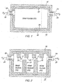
- FIG. 1 shows a cross section of a first embodiment of a storage container in accordance with the invention.
- FIG. 2 shows a cross section of a second embodiment of a storage container in accordance with the invention.
- FIG. 3 shows a cross section of a third embodiment of a storage container having external fins for improved heat dissipation.
- FIG. 4 shows a cross section of a fourth embodiment of a storage container having external fins for improved heat dissipation.
- FIG. 5 shows a cross section of one embodiment of the storage container associated with a thermal energy management system.
- FIG. 6 shows a cross section of another embodiment of a storage container associated with a thermal energy management system.
- FIG. 7 shows a cross section of yet another embodiment of a storage container associated with a thermal energy management system.
- FIG. 8 shows a cross section of still another embodiment of a storage container associated with a thermal energy management system.
- FIG. 9 shows a block diagram of a heat pump (e.g., refrigerator) which may be used in conjunction with any embodiment in FIG. 5 through FIG. 8, inclusive.
- a heat pump e.g., refrigerator
- FIG. 1 illustrates a first embodiment of a container 10 for storing a gaseous fuel, such as hydrogen.
- the container 10 comprises an outer shell 18 having an inlet 26 for inputting hydrogen gas and an outlet 28 for outputting hydrogen gas.
- An inlet valve 22 is associated with the inlet 26 for controlling the input of gas into the container.
- An outlet valve 24 is associated with the outlet 28 for controlling the exit of gas from the container.
- the outlet valve 24 may comprise a pressure regulator for regulating or metering the flow of gas exiting from the container 10.
- a thermally conductive liner 20 lines an interior of the outer shell 18.
- An inner hydride core 30 is in communication with the inlet 26 and the outlet 28 for storing the hydrogen gas.
- Hydride is a binary compound of hydrogen, usually formed with a more electropositive element, such as a metal.
- the combination of the thermally conductive liner 20 and the inner hydride core 30 may form a storage system for gaseous fuel that is durable, resistant to fatigue, and supports rapid heat transfer in and out of the storage system.
- the thermally conductive liner 20 may be configured in accordance with various alternate techniques. Under a first technique, the thermally conductive liner 20 comprises a carbon foam core.
- the carbon foam has a desired level of heat transfer and is generally non-rigid.
- Carbon foam may be composed of a carbon-fiber precursor or carbon-graphite that forms a cellular matrix.
- the carbon foam may have spatial pockets that are capable of storing gas.
- Carbon foam is generally chemically inert and may be configured for high thermal conductivity.
- the compressive strength of carbon foam may be less than the burst strength of the container 10, such that the carbon foam liner 20 gives or allows some compression of the carbon foam upon exposure to the storage of higher pressure gas.
- the thermally conductive liner 20 comprises a carbon foam material that generally conforms to a shape of the metallic shell.
- the thermally conductive liner 20 comprises a carbon foam coating that coats an interior of the outer shell 18.
- the thermally conductive liner 20 comprises a graphite foam having a desired high thermal conductivity.
- the thermally conductive liner 20 protects the outer shell (e.g., metallic outer shell 18) from hydride expansion during recharging of the container or tank with pressurized hydrogen gas.
- the thermally conductive liner 20 transfers heat from the hydrogen gas during filling or recharging or compressing of hydrogen gas within the container or tank to improve the ability to fully charge the tank and improve the accuracy of fuel readings.
- the outer shell 18 is constructed of a metallic material selected from the group consisting of steel, aluminum, a steel alloy, and an aluminum alloy.
- FIG. 2 illustrates a second embodiment of the container 12.
- the container 12 of FIG. 2 is similar to the container 10 of FIG. 1 except the container 12 of FIG. 2 includes a thermally conductive liner 31.
- the thermally conductive liner 31 comprises a carbon foam material with a series of fins 32 interspersed with the inner hydride core 34 to enhance thermal transfer of thermal energy between the inner hydride core 34 and the ambient environment around the container 12.
- FIG. 3 illustrates a third embodiment of the container 14.
- the container 14 of FIG. 3 is similar to the container 10 of FIG. 1 except the container 14 of FIG. 3 further includes external fins 38 on the container 14 to enhance heat transfer from the container 14 to the ambient environment, where the ambient environment is cooler than the container.
- the external fins 38 may be integrated to the outer shell 36 of the container.
- the container 14 is air-cooled as shown, in an alternate embodiment the container may be water-cooled or liquid-cooled by surrounding the tank with tubing or channels for conducting a coolant.
- FIG. 4 illustrates a fourth embodiment of the container 16.
- the container 16 of FIG. 4 is similar to the container 12 of FIG. 2 except the container 16 of FIG. 4 further includes external fins 38 on the container 16 to enhance heat transfer from the container 16 to the ambient environment, where the ambient environment is cooler than the container.
- the external fins 38 may be integral to the outer shell 36 of the container.
- the container 16 is air-cooled as shown, in an alternate embodiment the container may be water-cooled or liquid-cooled by surrounding the tank with tubing or channels for conducting a coolant.
- the container may comprise a fuel tank of a hydrogen-powered vehicle selected from the group consisting of a fuel-cell vehicle and an internal combustion engine vehicle.
- FIG. 5 is a block diagram of one embodiment of a storage container 510 associated with an energy management system.
- the storage container 510 of FIG. 5 is similar to the storage container 10 of FIG. 1, except that storage container 510 further comprises an inlet flow sensor 114, an outlet flow sensor 115, and coolant lines 117.
- Like reference numbers indicate like elements in FIG. 1 and FIG. 5.
- the coolant lines 117 are in thermal communication with at least one of the outer shell 18 and the thermally conductive liner 20 of the storage tank.
- the thermally conductive layer 20 may comprise a carbon foam material or graphite foam material.
- Coolant that flows into coolant lines 117 is indicated by "X's.” in FIG. 5. Coolant that flows out of the cross section of the coolant lines 117, is indicated by "dots.”
- An inlet flow sensor 114 and an outlet flow sensor 115 are associated with the inlet 26 and the outlet 28, or the inlet valve 22 and the outlet valve 24.
- the inlet flow sensor 114 and the outlet flow sensor 115 communicate a signal or data message with a thermal management controller 100.
- the thermal management controller 100 controls the flow of coolant or other fluid through valve assembly 102.
- the valve assembly 102 may route the coolant or fluid to one or more of the following components: a propulsion unit 106, a first pump 104, a second pump 110, a first heat exchanger 108 and a second heat exchanger 112.
- valve assembly 102 may statically interconnect the propulsion unit 106 to the first heat exchanger 108 during both the dispensing mode and the refueling mode.
- an inlet flow sensor 114 detects whether hydrogen or gaseous fuel is flowing into the fuel tank through the inlet or inlet valve that meets or exceeds a minimum threshold. If the inlet flow sensor 114 detects the inbound flow of fuel into the storage tank, the inlet flow sensor 114 may generate or transmit a signal or data message. The inbound flow may need to exceed a minimum threshold to be material.
- an outlet flow sensor 115 detects whether hydrogen or gaseous fuel is flowing out of the fuel tank through the outlet or the outlet valve or pressure regulator. The outbound flow may need to exceed a minimum threshold (e.g., that fuel that is required for idling of the propulsion unit 106). The hydrogen or gaseous fuel may be used to power a propulsion unit 106. If the outlet flow sensor 115 detects the outbound flow of fuel from the storage tank, the outlet flow sensor 115 may generate or transmit a signal or data message.
- the thermal management system 501 receives or interprets signals or data messages from the inlet flow sensor 114, the outlet flow sensor 115, or both.
- the thermal management controller 100 determines whether the container 510 is in a dispensing mode or a refueling mode based on the signal associated with at least one of the inlet flow sensor 114 and the outlet flow sensor 115.
- a valve assembly 102 routes the coolant lines 117 in a dispensing mode to a first heat exchanger 108 that is in thermal communication with a propulsion unit 106 of a vehicle and for routing the coolant lines 117 in refueling mode to a second heat exchanger 112 associated with a temperature that is less than or equal to the ambient temperature outside of the vehicle.
- the valve assembly 102 may comprise electro-hydraulic valves, electro-mechanical valves, servo-valves, or flow metering devices controllable by control signals or control data messages generated by the thermal management controller 100.
- the propulsion unit 106 may comprise an internal combustion engine associated with a coolant jacket and a first pump 104.
- the first pump 104 facilitates the circulation of coolant within the propulsion unit 106 and the first heat exchanger 108.
- the coolant jacket is generally coupled in series with the first heat exchanger 108.
- the propulsion unit 106 comprises a fuel cell associated with a coolant chamber and a first pump 104 for circulating coolant; the coolant chamber coupled in series with the first heat exchanger 108.
- the second heat exchanger 112 is associated with a second pump 110 for circulating coolant between the second heat exchanger 112 and the coolant lines 117.
- the valve assembly 102 may be associated with multiple ports for connection to fluid lines.
- the ports are labeled A, B, C, D, E and F.
- port A is connected to port F;
- port B is connected to port E, and
- ports C and D are not connected to the other ports.
- port A is connected to port B;
- port D is connected to port E; and
- Port C is connected to port F.
- the storage container 512 of FIG. 6. is similar to the storage container 12 of FIG. 2 except the storage container of FIG. 6 has coolant lines 117 running through or embedded in the thermally conductive liner 31.
- coolant lines 117 running through or embedded in the thermally conductive liner 31.
- the thermally conductive liner 31 has fins 32 and the coolant lines 117 may run through or be embedded in the fins 32.
- the thermally conductive liner 31 comprises a carbon foam material with a series of fins 32 interspersed with the inner hydride core to enhance thermal transfer of thermal energy between the hydride and the ambient environment around the container. Elastomeric, hermetically welded joints, or high pressure seals may be needed where the coolant lines 117 enter the interior of the tank 512 from the exterior. Coolant that flows into coolant lines 117 is indicated by "X's.” in FIG. 6. Coolant that flows out of the cross section of the coolant lines 117, is indicated by "dots.”
- the storage container of FIG. 7 is similar to the storage container 14 of FIG. 3 except that the storage container of FIG. 7 has coolant lines 117 positioned in generally parallel channels formed by external fins 38 on the exterior of the storage container.
- the coolant lines 117 of FIG. 7 are in thermal communication with the thermally conductive liner 20 via the outer shell 36. In FIG. 7, the coolant lines 117 do not run through the outer shell 36. Coolant that flows into coolant lines 117 is indicated by "X's.” in FIG. 7. Coolant that flows out of the cross section of the coolant lines 117, is indicated by "dots.”
- the storage container of FIG. 8 is similar to the storage container 16 of FIG. 4 except that the storage container of FIG. 8 has coolant lines 117 running through or embedded in the thermally conductive liner 20.
- the outer shell 36 comprises external fins 38 for promoting heat dissipation from the container 516 during recharging of the container. Elastomeric, hermetically welded joints, or high pressure seals may be needed where the coolant lines 117 interface with the outer shell 36 or enter the interior of the tank from the exterior. Coolant that flows into coolant lines 117 is indicated by "X's.” in FIG. 8. Coolant that flows out of the cross section of the coolant lines 117, is indicated by "dots.”
- FIG. 9 shows a block diagram of a heat pump 900 (e.g., refrigerator) which may be used in conjunction with any embodiment in FIG. 5 through FIG. 8, inclusive.
- a heat pump 900 e.g., refrigerator
- the heat pump 900 (e.g., refrigerator) comprises a compressor 901 for compressing a refrigerant (e.g., ammonia, Freon, or otherwise).
- the compressor 901 moves the refrigerant from a low pressure side to a high pressure side of the heat pump 900.
- the compressor 901 may be driven by the propulsion unit 106 via a belt, a chain, a gear system, or otherwise. Alternatively, the compressor 901 may be driven by an electric motor attached thereto.
- the inlet flow sensor 114 may communicate a data message or signal to the thermal management controller 100, a controller for the motor, or to an electromagnetic clutch driven by the propulsion unit to activate (e.g., rotate the compressor shaft) the compressor 901.
- An output of the compressor 901 is coupled to a condenser 902 via a high pressure line 908.
- the compressed refrigerant may condense to a liquid phase as it radiates heat.
- the condenser 902 is connected to an expansion valve 903 via a high pressure line 908.
- the expansion valve 903 forms a barrier between the high pressure side and the low pressure side of the heat pump 900.
- the high pressure side of the expansion valve 903 is coupled to the condenser 902, whereas, the low pressure side of the expansion valve 903 is coupled to the evaporator 904 via a low pressure line 907.
- the refrigerant evaporates to a gas phase as it sinks or absorbs heat.
- the evaporator 904 is coupled to the compressor 901 via a low pressure line 907.
- a cool temperature zone 905 is associated with the evaporator 904.
- a hot zone 906 or high temperature zone is associated with the condenser 902.
- the second heat exchanger 112 may be placed in the cool temperature zone 905 associated with the heat pump 900.
- the second heat exchanger 112 may be placed adjacent to an evaporator 904 or in thermal communication with the evaporator coils (e.g., cooling coils) of the evaporator 904. If the evaporator 904 and the second heat exchanger 112 are positioned in such thermal communication, the heat pump 900 can facilitate increased sinking or absorption of heat through the second heat exchanger 112.
- any embodiment of the storage container associated with the thermal energy management system disclosed herein, including the embodiments of FIG. 5 through FIG. 9, may be used to reduce or minimize the fueling or refueling time to add hydrogen or other gaseous fuels to the storage container of a vehicle by efficiently dissipating thermal energy generated during refueling.
- the laws of thermodynamics e.g., energy conservation
- the thermal energy inputted to the storage container from the propulsion unit to release hydrogen from the hydride during the dispensing mode e.g., vehicle operational mode
- the dispensing mode occurs over a much greater time than the refueling process, which leads to great amount of heat to be dissipated in a short time during the refueling process.
- the input valve and the outlet valve may be replaced with a single valve that functions both as an inlet flow controller and an outlet flow controller.
Landscapes
- Chemical & Material Sciences (AREA)
- Engineering & Computer Science (AREA)
- Chemical Kinetics & Catalysis (AREA)
- Sustainable Development (AREA)
- Sustainable Energy (AREA)
- Manufacturing & Machinery (AREA)
- Life Sciences & Earth Sciences (AREA)
- Electrochemistry (AREA)
- General Chemical & Material Sciences (AREA)
- Mechanical Engineering (AREA)
- General Engineering & Computer Science (AREA)
- Combustion & Propulsion (AREA)
- Oil, Petroleum & Natural Gas (AREA)
- Organic Chemistry (AREA)
- Filling Or Discharging Of Gas Storage Vessels (AREA)
Abstract
Description
- This invention relates to a storage container associated with a thermal energy management system.
- Gaseous fuels may be stored in metallic or polymeric tanks. Gaseous fuels include hydrogen, methane, propane, ether, natural gas, acetylene, and other flammable gases or mixtures thereof. The storage capacity of a tank may be based upon the burst strength and maximum safe operating pressure of the tank over a defined ambient temperature range. To increase the storage capacity of a tank, hydrogen may be stored as a hydride. Hydride is a binary compound of hydrogen, usually formed with a more electropositive element. When a storage tank is filled with hydrogen, the hydrogen may be converted to a hydride. The hydride material expands during the filling with hydrogen gas and contracts during the release of the hydrogen gas. Accordingly, the life of the tank may be shortened by fatigue cracks from the foregoing expansion-contraction cycle.
- It is therefore an object of the present invention to overcome the disadvantage mentioned above.
- A container for storing hydrogen comprises an outer shell having an inlet for inputting hydrogen gas and an outlet for outputting hydrogen gas. A thermally conductive liner lines an interior of the outer shell. An inner hydride core is in communication with the inlet and the outlet for storing the hydrogen gas. Coolant lines are in thermal communication with the storage container. A thermal management controller determines whether the container is in a dispensing mode or a refueling mode. If the container is in the dispensing mode, the coolant lines may be routed to a first heat exchanger that is in thermal communication with a propulsion unit of a vehicle. However, if the container is in the refueling mode, the coolant lines may be routed to a second heat exchanger associated with a temperature that is less than or equal to the ambient temperature outside of the vehicle.
- For a complete understanding of the objects, techniques, and structure of the invention reference should be made to the following detailed description and accompanying drawings, wherein:
- FIG. 1 shows a cross section of a first embodiment of a storage container in accordance with the invention.
- FIG. 2 shows a cross section of a second embodiment of a storage container in accordance with the invention.
- FIG. 3 shows a cross section of a third embodiment of a storage container having external fins for improved heat dissipation.
- FIG. 4 shows a cross section of a fourth embodiment of a storage container having external fins for improved heat dissipation.
- FIG. 5 shows a cross section of one embodiment of the storage container associated with a thermal energy management system.
- FIG. 6 shows a cross section of another embodiment of a storage container associated with a thermal energy management system.
- FIG. 7 shows a cross section of yet another embodiment of a storage container associated with a thermal energy management system.
- FIG. 8 shows a cross section of still another embodiment of a storage container associated with a thermal energy management system.
- FIG. 9 shows a block diagram of a heat pump (e.g., refrigerator) which may be used in conjunction with any embodiment in FIG. 5 through FIG. 8, inclusive.
- FIG. 1 illustrates a first embodiment of a
container 10 for storing a gaseous fuel, such as hydrogen. Thecontainer 10 comprises anouter shell 18 having aninlet 26 for inputting hydrogen gas and anoutlet 28 for outputting hydrogen gas. Aninlet valve 22 is associated with theinlet 26 for controlling the input of gas into the container. Anoutlet valve 24 is associated with theoutlet 28 for controlling the exit of gas from the container. Theoutlet valve 24 may comprise a pressure regulator for regulating or metering the flow of gas exiting from thecontainer 10. A thermallyconductive liner 20 lines an interior of theouter shell 18. Aninner hydride core 30 is in communication with theinlet 26 and theoutlet 28 for storing the hydrogen gas. - Hydride is a binary compound of hydrogen, usually formed with a more electropositive element, such as a metal. The combination of the thermally
conductive liner 20 and theinner hydride core 30 may form a storage system for gaseous fuel that is durable, resistant to fatigue, and supports rapid heat transfer in and out of the storage system. - The thermally
conductive liner 20 may be configured in accordance with various alternate techniques. Under a first technique, the thermallyconductive liner 20 comprises a carbon foam core. The carbon foam has a desired level of heat transfer and is generally non-rigid. Carbon foam may be composed of a carbon-fiber precursor or carbon-graphite that forms a cellular matrix. The carbon foam may have spatial pockets that are capable of storing gas. Carbon foam is generally chemically inert and may be configured for high thermal conductivity. The compressive strength of carbon foam may be less than the burst strength of thecontainer 10, such that thecarbon foam liner 20 gives or allows some compression of the carbon foam upon exposure to the storage of higher pressure gas. - Under a second technique, the thermally
conductive liner 20 comprises a carbon foam material that generally conforms to a shape of the metallic shell. Under a third technique, the thermallyconductive liner 20 comprises a carbon foam coating that coats an interior of theouter shell 18. Under a fourth technique, the thermallyconductive liner 20 comprises a graphite foam having a desired high thermal conductivity. - The thermally
conductive liner 20 protects the outer shell (e.g., metallic outer shell 18) from hydride expansion during recharging of the container or tank with pressurized hydrogen gas. The thermallyconductive liner 20 transfers heat from the hydrogen gas during filling or recharging or compressing of hydrogen gas within the container or tank to improve the ability to fully charge the tank and improve the accuracy of fuel readings. - In one embodiment, the
outer shell 18 is constructed of a metallic material selected from the group consisting of steel, aluminum, a steel alloy, and an aluminum alloy. - FIG. 2 illustrates a second embodiment of the container 12. The container 12 of FIG. 2 is similar to the
container 10 of FIG. 1 except the container 12 of FIG. 2 includes a thermallyconductive liner 31. In one embodiment, the thermallyconductive liner 31 comprises a carbon foam material with a series offins 32 interspersed with theinner hydride core 34 to enhance thermal transfer of thermal energy between theinner hydride core 34 and the ambient environment around the container 12. - FIG. 3 illustrates a third embodiment of the
container 14. Thecontainer 14 of FIG. 3 is similar to thecontainer 10 of FIG. 1 except thecontainer 14 of FIG. 3 further includesexternal fins 38 on thecontainer 14 to enhance heat transfer from thecontainer 14 to the ambient environment, where the ambient environment is cooler than the container. Theexternal fins 38 may be integrated to theouter shell 36 of the container. Although thecontainer 14 is air-cooled as shown, in an alternate embodiment the container may be water-cooled or liquid-cooled by surrounding the tank with tubing or channels for conducting a coolant. - FIG. 4 illustrates a fourth embodiment of the
container 16. Thecontainer 16 of FIG. 4 is similar to the container 12 of FIG. 2 except thecontainer 16 of FIG. 4 further includesexternal fins 38 on thecontainer 16 to enhance heat transfer from thecontainer 16 to the ambient environment, where the ambient environment is cooler than the container. Theexternal fins 38 may be integral to theouter shell 36 of the container. Although thecontainer 16 is air-cooled as shown, in an alternate embodiment the container may be water-cooled or liquid-cooled by surrounding the tank with tubing or channels for conducting a coolant. - Any of the embodiments of the
containers - FIG. 5 is a block diagram of one embodiment of a
storage container 510 associated with an energy management system. Thestorage container 510 of FIG. 5 is similar to thestorage container 10 of FIG. 1, except thatstorage container 510 further comprises aninlet flow sensor 114, anoutlet flow sensor 115, andcoolant lines 117. Like reference numbers indicate like elements in FIG. 1 and FIG. 5. - The coolant lines 117 are in thermal communication with at least one of the
outer shell 18 and the thermallyconductive liner 20 of the storage tank. The thermallyconductive layer 20 may comprise a carbon foam material or graphite foam material. Although thecoolant lines 117 are routed along an exterior of theouter shell 18 in FIG. 5, other configurations of thecoolant lines 117 relative to the interior and exterior of the storage tank are possible. - The flow of the coolant during operation of the vehicle or storage tank is illustrated by the symbols in the cross-section of the coolant lines 117. Coolant that flows into
coolant lines 117 is indicated by "X's." in FIG. 5. Coolant that flows out of the cross section of thecoolant lines 117, is indicated by "dots." - An
inlet flow sensor 114 and anoutlet flow sensor 115 are associated with theinlet 26 and theoutlet 28, or theinlet valve 22 and theoutlet valve 24. Theinlet flow sensor 114 and theoutlet flow sensor 115 communicate a signal or data message with athermal management controller 100. In turn, thethermal management controller 100 controls the flow of coolant or other fluid throughvalve assembly 102. Thevalve assembly 102 may route the coolant or fluid to one or more of the following components: apropulsion unit 106, afirst pump 104, asecond pump 110, afirst heat exchanger 108 and asecond heat exchanger 112. - In one configuration, the
valve assembly 102, or other lines or piping may statically interconnect thepropulsion unit 106 to thefirst heat exchanger 108 during both the dispensing mode and the refueling mode. - In one embodiment, an
inlet flow sensor 114 detects whether hydrogen or gaseous fuel is flowing into the fuel tank through the inlet or inlet valve that meets or exceeds a minimum threshold. If theinlet flow sensor 114 detects the inbound flow of fuel into the storage tank, theinlet flow sensor 114 may generate or transmit a signal or data message. The inbound flow may need to exceed a minimum threshold to be material. Similarly, anoutlet flow sensor 115 detects whether hydrogen or gaseous fuel is flowing out of the fuel tank through the outlet or the outlet valve or pressure regulator. The outbound flow may need to exceed a minimum threshold (e.g., that fuel that is required for idling of the propulsion unit 106). The hydrogen or gaseous fuel may be used to power apropulsion unit 106. If theoutlet flow sensor 115 detects the outbound flow of fuel from the storage tank, theoutlet flow sensor 115 may generate or transmit a signal or data message. - The
thermal management system 501 receives or interprets signals or data messages from theinlet flow sensor 114, theoutlet flow sensor 115, or both. Thethermal management controller 100 determines whether thecontainer 510 is in a dispensing mode or a refueling mode based on the signal associated with at least one of theinlet flow sensor 114 and theoutlet flow sensor 115. - A
valve assembly 102 routes thecoolant lines 117 in a dispensing mode to afirst heat exchanger 108 that is in thermal communication with apropulsion unit 106 of a vehicle and for routing thecoolant lines 117 in refueling mode to asecond heat exchanger 112 associated with a temperature that is less than or equal to the ambient temperature outside of the vehicle. Thevalve assembly 102 may comprise electro-hydraulic valves, electro-mechanical valves, servo-valves, or flow metering devices controllable by control signals or control data messages generated by thethermal management controller 100. - In one embodiment, the
propulsion unit 106 may comprise an internal combustion engine associated with a coolant jacket and afirst pump 104. Thefirst pump 104 facilitates the circulation of coolant within thepropulsion unit 106 and thefirst heat exchanger 108. The coolant jacket is generally coupled in series with thefirst heat exchanger 108. In another embodiment, thepropulsion unit 106 comprises a fuel cell associated with a coolant chamber and afirst pump 104 for circulating coolant; the coolant chamber coupled in series with thefirst heat exchanger 108. - The
second heat exchanger 112 is associated with asecond pump 110 for circulating coolant between thesecond heat exchanger 112 and the coolant lines 117. Thevalve assembly 102 may be associated with multiple ports for connection to fluid lines. Here, in FIG. 5, the ports are labeled A, B, C, D, E and F. During the dispensing mode, port A is connected to port F; port B is connected to port E, and ports C and D are not connected to the other ports. During the refueling mode, port A is connected to port B; port D is connected to port E; and Port C is connected to port F. - The
storage container 512 of FIG. 6. is similar to the storage container 12 of FIG. 2 except the storage container of FIG. 6 hascoolant lines 117 running through or embedded in the thermallyconductive liner 31. Like reference numbers in FIG. 2 and FIG. 5 indicate like elements. - The thermally
conductive liner 31 hasfins 32 and thecoolant lines 117 may run through or be embedded in thefins 32. The thermallyconductive liner 31 comprises a carbon foam material with a series offins 32 interspersed with the inner hydride core to enhance thermal transfer of thermal energy between the hydride and the ambient environment around the container. Elastomeric, hermetically welded joints, or high pressure seals may be needed where thecoolant lines 117 enter the interior of thetank 512 from the exterior. Coolant that flows intocoolant lines 117 is indicated by "X's." in FIG. 6. Coolant that flows out of the cross section of thecoolant lines 117, is indicated by "dots." - The storage container of FIG. 7 is similar to the
storage container 14 of FIG. 3 except that the storage container of FIG. 7 hascoolant lines 117 positioned in generally parallel channels formed byexternal fins 38 on the exterior of the storage container. The coolant lines 117 of FIG. 7 are in thermal communication with the thermallyconductive liner 20 via theouter shell 36. In FIG. 7, thecoolant lines 117 do not run through theouter shell 36. Coolant that flows intocoolant lines 117 is indicated by "X's." in FIG. 7. Coolant that flows out of the cross section of thecoolant lines 117, is indicated by "dots." - The storage container of FIG. 8 is similar to the
storage container 16 of FIG. 4 except that the storage container of FIG. 8 hascoolant lines 117 running through or embedded in the thermallyconductive liner 20. Theouter shell 36 comprisesexternal fins 38 for promoting heat dissipation from thecontainer 516 during recharging of the container. Elastomeric, hermetically welded joints, or high pressure seals may be needed where thecoolant lines 117 interface with theouter shell 36 or enter the interior of the tank from the exterior. Coolant that flows intocoolant lines 117 is indicated by "X's." in FIG. 8. Coolant that flows out of the cross section of thecoolant lines 117, is indicated by "dots." - FIG. 9 shows a block diagram of a heat pump 900 (e.g., refrigerator) which may be used in conjunction with any embodiment in FIG. 5 through FIG. 8, inclusive.
- The heat pump 900 (e.g., refrigerator) comprises a
compressor 901 for compressing a refrigerant (e.g., ammonia, Freon, or otherwise). Thecompressor 901 moves the refrigerant from a low pressure side to a high pressure side of theheat pump 900. Thecompressor 901 may be driven by thepropulsion unit 106 via a belt, a chain, a gear system, or otherwise. Alternatively, thecompressor 901 may be driven by an electric motor attached thereto. If theinlet flow sensor 114 detects the flow of hydrogen gas into the container that meets or exceeds a minimum threshold or if the container is in the refueling mode, theinlet flow sensor 114 may communicate a data message or signal to thethermal management controller 100, a controller for the motor, or to an electromagnetic clutch driven by the propulsion unit to activate (e.g., rotate the compressor shaft) thecompressor 901. - An output of the
compressor 901 is coupled to acondenser 902 via ahigh pressure line 908. In thecondenser 902, the compressed refrigerant may condense to a liquid phase as it radiates heat. Thecondenser 902 is connected to anexpansion valve 903 via ahigh pressure line 908. Theexpansion valve 903 forms a barrier between the high pressure side and the low pressure side of theheat pump 900. The high pressure side of theexpansion valve 903 is coupled to thecondenser 902, whereas, the low pressure side of theexpansion valve 903 is coupled to theevaporator 904 via alow pressure line 907. In theevaporator 904, the refrigerant evaporates to a gas phase as it sinks or absorbs heat. Theevaporator 904 is coupled to thecompressor 901 via alow pressure line 907. - A
cool temperature zone 905 is associated with theevaporator 904. Ahot zone 906 or high temperature zone is associated with thecondenser 902. Thesecond heat exchanger 112 may be placed in thecool temperature zone 905 associated with theheat pump 900. For example, thesecond heat exchanger 112 may be placed adjacent to anevaporator 904 or in thermal communication with the evaporator coils (e.g., cooling coils) of theevaporator 904. If theevaporator 904 and thesecond heat exchanger 112 are positioned in such thermal communication, theheat pump 900 can facilitate increased sinking or absorption of heat through thesecond heat exchanger 112. - Any embodiment of the storage container associated with the thermal energy management system disclosed herein, including the embodiments of FIG. 5 through FIG. 9, may be used to reduce or minimize the fueling or refueling time to add hydrogen or other gaseous fuels to the storage container of a vehicle by efficiently dissipating thermal energy generated during refueling. The laws of thermodynamics (e.g., energy conservation) establish that the thermal energy inputted to the storage container from the propulsion unit to release hydrogen from the hydride during the dispensing mode (e.g., vehicle operational mode) is approximately equal to the thermal energy dissipated during the refueling process. However, the dispensing mode occurs over a much greater time than the refueling process, which leads to great amount of heat to be dissipated in a short time during the refueling process.
- Having described various preferred embodiments, it will become apparent that various modifications can be made without departing from the scope of the invention as defined in the accompanying claims. For example, in one alternate embodiment, the input valve and the outlet valve may be replaced with a single valve that functions both as an inlet flow controller and an outlet flow controller.
Claims (11)
- A container for (10, 510) storing hydrogen comprising:an outer shell (18) having an inlet (26) for inputting hydrogen gas and an outlet (28) for outputting hydrogen gas;a thermally conductive liner (20, 31) lining an interior of the outer shell (16);an inner hydride core (30, 34) in communication with the inlet (26) and the outlet (28) for storing the hydrogen gas;coolant lines (117) in thermal communication with at least one of the outer shell (18) and the thermally conductive liner (20, 31);an inlet flow sensor (114) and an outlet flow sensor (115) associated with the inlet (26) and the outlet (28), respectively;a thermal management controller (100) for determining whether the container (510) is in a dispensing mode or a refueling mode based on a signal associated with at least one of the inlet flow sensor (114) and the outlet flow sensor (115);a first heat exchanger (108) in thermal communication with a propulsion unit (106) of a vehicle;a second heat exchanger (112) associated with a temperature that is less than or equal to the ambient temperature outside of the vehicle; anda valve assembly (102) for routing the coolant lines (117) in a dispensing mode to the first heat exchanger (108) and for routing the coolant lines (117) in refueling mode to the second heat exchanger (112).
- The system according to claim 1 wherein the propulsion unit (106) comprises an internal combustion engine associated with a coolant jacket and a first pump (104) for circulating coolant; the coolant jacket coupled in series with the first heat exchanger (108).
- The system according to claim 1 or 2 wherein the second heat exchanger (112) is associated with a second pump (110) for circulating coolant between the second heat exchanger (112) and the coolant lines (117). according to one of the preceding claims
- The system according to one of the preceding claims wherein the second heat exchanger (112) is in thermal communication with cooling coils or evaporator of a heat pump (900).
- The system according to one of the preceding claims wherein the propulsion unit (106) comprises a fuel cell associated with a coolant chamber and a first pump (104) for circulating coolant; the coolant chamber coupled in series with the first heat exchanger (108).
- The system according to one of the preceding claims wherein the coolant lines (117) are routed along an exterior of the outer shell (18) and/or wherein at least part of the coolant lines (117) are embedded in the thermally conductive liner (20).
- The container according to one of the preceding claims wherein the thermally conductive liner (20, 31) comprises a carbon foam core.
- The container according one of the preceding claims wherein the thermally conductive liner (20, 31) comprises a carbon foam material with a series of fins (32) interspersed with the inner hydride core (30, 34) to enhance thermal transfer of thermal energy between the hydride and the ambient environment around the container (10, 510).
- The container according to one of the preceding claims wherein the container (510) comprises a fuel tank of a hydrogen-powered vehicle selected from the group consisting of a fuel-cell vehicle and an internal combustion engine vehicle.
- The container according to one of the preceding claims wherein the outer shell (36) comprises external fins (38) for promoting heat dissipation from the container (14, 514) during recharging of the container (14, 514) and wherein the coolant lines (117) preferably are routed at least partially within channels formed by the external fins (38).
- A method for storing hydrogen comprising:providing an inlet (26) for inputting hydrogen gas and an outlet (28) for outputting hydrogen gas, a thermally conductive liner (31) lining an interior of an outer shell (18), an inner hydride core (34) in communication with the inlet (26) and the outlet (28) for storing the hydrogen gas, and coolant lines (117) in thermal communication with at least one of the outer shell (18) and the thermally conductive liner (31);determining whether the container (510) is in a dispensing mode or a refueling mode based on a signal associated with at least one of the inlet flow sensor (114) and the outlet flow sensor (115) associated with the inlet (26) and the outlet (28), respectively;routing the coolant lines (117) to a first heat exchanger (108) that is in thermal communication with a propulsion unit (106) of a vehicle if the container (510) is in the dispensing mode and routing the coolant lines (117) to a second heat exchanger (108) associated with a temperature that is less than or equal to the ambient temperature outside of the vehicle, if the container (510) is in the refueling mode.
Applications Claiming Priority (1)
| Application Number | Priority Date | Filing Date | Title |
|---|---|---|---|
| US11/177,858 US7323043B2 (en) | 2003-07-28 | 2005-07-08 | Storage container associated with a thermal energy management system |
Publications (2)
| Publication Number | Publication Date |
|---|---|
| EP1741972A2 true EP1741972A2 (en) | 2007-01-10 |
| EP1741972A3 EP1741972A3 (en) | 2011-11-30 |
Family
ID=37310849
Family Applications (1)
| Application Number | Title | Priority Date | Filing Date |
|---|---|---|---|
| EP06116718A Withdrawn EP1741972A3 (en) | 2005-07-08 | 2006-07-06 | Storage container associated with a thermal energy management system |
Country Status (2)
| Country | Link |
|---|---|
| US (1) | US7323043B2 (en) |
| EP (1) | EP1741972A3 (en) |
Cited By (3)
| Publication number | Priority date | Publication date | Assignee | Title |
|---|---|---|---|---|
| WO2008055735A1 (en) * | 2006-11-06 | 2008-05-15 | Robert Bosch Gmbh | Fluid accumulator comprising a heat exchanger |
| EP1958281A1 (en) * | 2005-11-30 | 2008-08-20 | The University of Washington | Carbon-based foam nanocomposite hydrogen storage material |
| US20220219840A1 (en) * | 2021-01-08 | 2022-07-14 | Ivaylo Trendafilov Vasilev | System and Method of Generating a Momentum Change in a Vehicle by Phase Changing Matter in a Closed System |
Families Citing this family (34)
| Publication number | Priority date | Publication date | Assignee | Title |
|---|---|---|---|---|
| US8372184B2 (en) | 2005-04-22 | 2013-02-12 | Societe Bic | Composite hydrogen storage material and methods related thereto |
| US7771512B2 (en) * | 2005-06-24 | 2010-08-10 | Washington State University Research Foundation | Apparatus with high surface area nanostructures for hydrogen storage, and methods of storing hydrogen |
| EP1917101A4 (en) * | 2005-06-24 | 2012-02-08 | Univ Washington State Res Fdn | PROCESS FOR MANUFACTURING AND COATING NANOSTRUCTURED COMPONENTS |
| DE102006020394B4 (en) * | 2006-04-28 | 2010-07-22 | Daimler Ag | Hydrogen storage and method for filling a hydrogen storage |
| US7563305B2 (en) * | 2006-06-23 | 2009-07-21 | Angstrom Power Incorporated | Fluid enclosure and methods related thereto |
| DE102006045920A1 (en) * | 2006-09-28 | 2008-04-03 | Robert Bosch Gmbh | fluid reservoir |
| US8372561B2 (en) * | 2007-03-21 | 2013-02-12 | Societe Bic | Composite fluid storage unit with internal fluid distribution feature |
| CN101970104B (en) * | 2007-11-09 | 2013-11-06 | 华盛顿州立大学研究基金会 | Catalysts and related methods |
| US20090159258A1 (en) * | 2007-12-19 | 2009-06-25 | Kiyoshi Handa | Internal Gas Warming For High Pressure Gas Storage Cylinders With Metal Liners |
| KR101120574B1 (en) * | 2008-12-22 | 2012-03-09 | 한국전자통신연구원 | gas storage structure and gas storage apparatus using thereof |
| US8636836B2 (en) | 2009-02-04 | 2014-01-28 | Purdue Research Foundation | Finned heat exchangers for metal hydride storage systems |
| WO2010091178A1 (en) | 2009-02-04 | 2010-08-12 | Purdue Research Foundation | Coiled and microchannel heat exchangers for metal hydride storage systems |
| US8147599B2 (en) | 2009-02-17 | 2012-04-03 | Mcalister Technologies, Llc | Apparatuses and methods for storing and/or filtering a substance |
| TW201115096A (en) * | 2009-10-26 | 2011-05-01 | Chung Hsin Elec & Mach Mfg | Hygrogen storage device |
| US8454730B2 (en) | 2010-04-20 | 2013-06-04 | GM Global Technology Operations LLC | Method of operating gas storage and supply system |
| US8554390B2 (en) * | 2010-11-16 | 2013-10-08 | International Business Machines Corporation | Free cooling solution for a containerized data center |
| WO2013025643A2 (en) | 2011-08-12 | 2013-02-21 | Mcalister Technologies, Llc | Dynamic filtration system and associated methods |
| WO2013025654A2 (en) | 2011-08-12 | 2013-02-21 | Mcalister Technologies, Llc | Fluid distribution filter having spiral filter media and associated systems and methods |
| DE102011122352B4 (en) * | 2011-12-23 | 2015-10-29 | Astrium Gmbh | Tank for the separation of liquids in orbit |
| US9273829B2 (en) * | 2012-10-09 | 2016-03-01 | Basf Se | Sorption store for storing gaseous substances |
| US9243754B2 (en) * | 2012-10-09 | 2016-01-26 | Basf Se | Method of charging a sorption store with a gas |
| US9322510B2 (en) * | 2012-10-09 | 2016-04-26 | Basf Se | Method of charging a sorption store with a gas |
| US9534296B2 (en) | 2013-03-15 | 2017-01-03 | Mcalister Technologies, Llc | Methods of manufacture of engineered materials and devices |
| US9108144B2 (en) | 2013-05-21 | 2015-08-18 | Astrium Gmbh | Tank for separating liquid from gas under weightless conditions |
| EP2806204B1 (en) * | 2013-05-22 | 2017-05-24 | Astrium GmbH | Tank for the separation of liquids in orbit |
| US9079489B2 (en) | 2013-05-29 | 2015-07-14 | Mcalister Technologies, Llc | Methods for fuel tank recycling and net hydrogen fuel and carbon goods production along with associated apparatus and systems |
| US20160201855A1 (en) * | 2013-08-15 | 2016-07-14 | Basf Se | Sorption store with improved heat transfer |
| US10386121B2 (en) | 2013-10-21 | 2019-08-20 | Advanced Cooling Technologies, Inc. | Open-loop thermal management process and system |
| WO2016172430A1 (en) * | 2015-04-22 | 2016-10-27 | Keystone Engineering Company | Center of mass control of liquid tanks for spacecraft use |
| ES2774346T3 (en) | 2015-12-29 | 2020-07-20 | Hydro 2 Power S R L | Metal hydride device for hydrogen storage and transportation |
| EP3720807A4 (en) | 2017-12-08 | 2021-07-14 | Klatu Networks, Inc. | Monitoring and predicting failures of specialty equipment including liquid gas storage systems |
| GB2574673B (en) * | 2018-06-15 | 2020-06-17 | H2Go Power Ltd | Hydrogen storage device |
| US11032941B2 (en) * | 2019-03-28 | 2021-06-08 | Intel Corporation | Modular thermal energy management designs for data center computing |
| CN114939325B (en) * | 2022-06-07 | 2023-03-14 | 西安热工研究院有限公司 | Adsorption equipment support based on hot-fluid |
Citations (2)
| Publication number | Priority date | Publication date | Assignee | Title |
|---|---|---|---|---|
| US4302217A (en) | 1978-07-24 | 1981-11-24 | Teitel Robert J | Hydrogen supply system |
| CA2474615A1 (en) | 2002-01-31 | 2003-08-07 | Jfe Steel Corporation | Hybrid-type hydrogen storage container and method of storing hydrogen in such a container |
Family Cites Families (30)
| Publication number | Priority date | Publication date | Assignee | Title |
|---|---|---|---|---|
| US4211537A (en) * | 1978-07-24 | 1980-07-08 | Teitel Robert J | Hydrogen supply method |
| US4318890A (en) | 1978-10-02 | 1982-03-09 | Monahan Daniel E | Reactor for generating granular metal hydride |
| JPS62196500A (en) * | 1986-02-24 | 1987-08-29 | Agency Of Ind Science & Technol | Heat exchanging body using hydrogen absorbing alloy |
| US5092281A (en) | 1988-07-26 | 1992-03-03 | Kabushiki Kaisha Toyoda Jidoshokki Seisakusho | Hydrogen engine system |
| US5445099A (en) * | 1993-09-20 | 1995-08-29 | Rendina; David D. | Hydrogen hydride keel |
| US6015041A (en) * | 1996-04-01 | 2000-01-18 | Westinghouse Savannah River Company | Apparatus and methods for storing and releasing hydrogen |
| US6037032A (en) | 1997-09-02 | 2000-03-14 | Lockheed Martin Energy Research Corp. | Pitch-based carbon foam heat sink with phase change material |
| US6033506A (en) | 1997-09-02 | 2000-03-07 | Lockheed Martin Engery Research Corporation | Process for making carbon foam |
| JP2000088196A (en) | 1998-07-17 | 2000-03-31 | Equos Research Co Ltd | In-vehicle hydrogen storage alloy system |
| US6398994B1 (en) | 1999-09-21 | 2002-06-04 | Ut-Battelle, Llc | Method of casting pitch based foam |
| US6344159B1 (en) | 1999-09-21 | 2002-02-05 | Ut-Battelle, Llc | Method for extruding pitch based foam |
| US6287375B1 (en) | 1999-09-21 | 2001-09-11 | Ut-Battelle, Llc | Pitch based foam with particulate |
| US6627148B1 (en) | 1999-11-06 | 2003-09-30 | Energy Conversion Devices, Inc. | Safe, ecomomical transport of hydrogen in pelletized form |
| US6293110B1 (en) | 1999-12-17 | 2001-09-25 | Energy Conversion Devices, Inc. | Hydrogen cooled hydride storage unit |
| US6195999B1 (en) | 2000-01-06 | 2001-03-06 | General Motors Corporation | Electrochemical engine |
| JP4490557B2 (en) | 2000-06-09 | 2010-06-30 | 本田技研工業株式会社 | Rapid hydrogen filling method |
| JP2002124280A (en) | 2000-10-18 | 2002-04-26 | Honda Motor Co Ltd | Fuel cell power generation system |
| US6833118B2 (en) * | 2000-12-20 | 2004-12-21 | Texaco Ovonic Hydrogen Systems Llc | Hydrogen storage bed system including an integrated thermal management system |
| JP4705251B2 (en) * | 2001-01-26 | 2011-06-22 | 本田技研工業株式会社 | MH tank |
| US20050013770A1 (en) | 2001-06-29 | 2005-01-20 | Robert Schulz | Method for storing hydrogen in an hybrid form |
| US20030042008A1 (en) | 2001-06-29 | 2003-03-06 | Robert Schulz | Method for storing hydrogen in an hybrid form |
| US6430935B1 (en) | 2001-08-22 | 2002-08-13 | Ut-Battelle, Llc | Personal cooling air filtering device |
| EP1331289A1 (en) | 2002-01-22 | 2003-07-30 | Proton Energy Systems, Inc. | System and method for refueling a hydrogen vessel |
| US6918430B2 (en) | 2002-08-14 | 2005-07-19 | Texaco Ovonic Hydrogen Systems Llc | Onboard hydrogen storage unit with heat transfer system for use in a hydrogen powered vehicle |
| US6918382B2 (en) | 2002-08-26 | 2005-07-19 | Energy Conversion Devices, Inc. | Hydrogen powered scooter |
| JP4220762B2 (en) * | 2002-11-15 | 2009-02-04 | 株式会社豊田自動織機 | Solid filling tank |
| US7152665B2 (en) | 2003-05-08 | 2006-12-26 | Kabushiki Kaisha Toyota Jidoshokki | Pressure tank |
| JP4119304B2 (en) * | 2003-05-20 | 2008-07-16 | トヨタ自動車株式会社 | Gas storage equipment |
| US7781109B2 (en) | 2004-09-03 | 2010-08-24 | Gross Karl J | Hydrogen storage and integrated fuel cell assembly |
| JP4542414B2 (en) * | 2004-11-18 | 2010-09-15 | 株式会社豊田自動織機 | Hydrogen tank cooling system for hydrogen fuel vehicle |
-
2005
- 2005-07-08 US US11/177,858 patent/US7323043B2/en not_active Expired - Fee Related
-
2006
- 2006-07-06 EP EP06116718A patent/EP1741972A3/en not_active Withdrawn
Patent Citations (2)
| Publication number | Priority date | Publication date | Assignee | Title |
|---|---|---|---|---|
| US4302217A (en) | 1978-07-24 | 1981-11-24 | Teitel Robert J | Hydrogen supply system |
| CA2474615A1 (en) | 2002-01-31 | 2003-08-07 | Jfe Steel Corporation | Hybrid-type hydrogen storage container and method of storing hydrogen in such a container |
Cited By (4)
| Publication number | Priority date | Publication date | Assignee | Title |
|---|---|---|---|---|
| EP1958281A1 (en) * | 2005-11-30 | 2008-08-20 | The University of Washington | Carbon-based foam nanocomposite hydrogen storage material |
| WO2008055735A1 (en) * | 2006-11-06 | 2008-05-15 | Robert Bosch Gmbh | Fluid accumulator comprising a heat exchanger |
| US20220219840A1 (en) * | 2021-01-08 | 2022-07-14 | Ivaylo Trendafilov Vasilev | System and Method of Generating a Momentum Change in a Vehicle by Phase Changing Matter in a Closed System |
| US11897637B2 (en) * | 2021-01-08 | 2024-02-13 | Ivaylo Trendafilov Vasilev | System and method of generating a momentum change in a vehicle by phase changing matter in a closed system |
Also Published As
| Publication number | Publication date |
|---|---|
| US20050268647A1 (en) | 2005-12-08 |
| EP1741972A3 (en) | 2011-11-30 |
| US7323043B2 (en) | 2008-01-29 |
Similar Documents
| Publication | Publication Date | Title |
|---|---|---|
| US7323043B2 (en) | Storage container associated with a thermal energy management system | |
| US6969545B2 (en) | Hydrogen storage container | |
| EP2126455B1 (en) | Thermal management for high pressure gas storage tanks | |
| US8113709B2 (en) | High-pressure tank | |
| US7938149B2 (en) | Supplemental heat exchange for high pressure gas tank | |
| EP1826051B1 (en) | Hydrogen tank cooling device and cooling method in hydrogen fuel automobile, and hydrogen fuel automobile | |
| EP2140194B1 (en) | Gas flow management equipment for high pressure storage tanks | |
| US20080314050A1 (en) | No-vent liquid hydrogen storage and delivery system | |
| US20120168111A1 (en) | Heat transfer system utilizing thermal energy storage materials | |
| EP2212614B1 (en) | Warming and heat isolation for gas flow in on board high pressure storage tanks installed on gas fueled vehicles | |
| US20090297896A1 (en) | Method of using hydrogen storage tank and hydrogen storage tank | |
| US7410714B1 (en) | Unitized regenerative fuel cell system | |
| CN1235674C (en) | Hydrogen storage bed system including integrated thermal management system | |
| JP5197756B2 (en) | Internal gas warming for high pressure gas storage tanks with metal liners | |
| US20170012303A1 (en) | Thermal Conditioning Fluids For An Underwater Cryogenic Storage Vessel | |
| KR101186285B1 (en) | heat exchanger system for ship with hydrogen storage tank. | |
| EP0766778B1 (en) | Steam buffer for a steam engine plant | |
| JP2006177537A (en) | High pressure tank system | |
| CN117847402B (en) | Cryogenic tank unit with heat exchanger | |
| US20090139475A1 (en) | Engine cooling system including metal foam | |
| US11721858B2 (en) | SuCCoR: a super critical cooling regulator to mitigate heating of batteries and other devices | |
| JP2008025973A (en) | Heat exchange system | |
| US12613003B2 (en) | Hydrogen gas transfer system | |
| US4760713A (en) | Multiple heat sink cooling system for a burst power fuel cell | |
| US12304355B2 (en) | Augmented cooling system for vehicles powered by fuel cells |
Legal Events
| Date | Code | Title | Description |
|---|---|---|---|
| PUAI | Public reference made under article 153(3) epc to a published international application that has entered the european phase |
Free format text: ORIGINAL CODE: 0009012 |
|
| AK | Designated contracting states |
Kind code of ref document: A2 Designated state(s): AT BE BG CH CY CZ DE DK EE ES FI FR GB GR HU IE IS IT LI LT LU LV MC NL PL PT RO SE SI SK TR |
|
| AX | Request for extension of the european patent |
Extension state: AL BA HR MK YU |
|
| PUAL | Search report despatched |
Free format text: ORIGINAL CODE: 0009013 |
|
| AK | Designated contracting states |
Kind code of ref document: A3 Designated state(s): AT BE BG CH CY CZ DE DK EE ES FI FR GB GR HU IE IS IT LI LT LU LV MC NL PL PT RO SE SI SK TR |
|
| AX | Request for extension of the european patent |
Extension state: AL BA HR MK RS |
|
| RIC1 | Information provided on ipc code assigned before grant |
Ipc: F17C 11/00 20060101AFI20111026BHEP |
|
| 17P | Request for examination filed |
Effective date: 20120530 |
|
| AKX | Designation fees paid |
Designated state(s): DE GB |
|
| 17Q | First examination report despatched |
Effective date: 20130718 |
|
| GRAP | Despatch of communication of intention to grant a patent |
Free format text: ORIGINAL CODE: EPIDOSNIGR1 |
|
| RIC1 | Information provided on ipc code assigned before grant |
Ipc: H01M 8/04082 20160101ALI20171017BHEP Ipc: C10J 3/78 20060101AFI20171017BHEP Ipc: F17C 11/00 20060101ALI20171017BHEP Ipc: H01M 8/04 20160101ALI20171017BHEP |
|
| INTG | Intention to grant announced |
Effective date: 20171115 |
|
| GRAS | Grant fee paid |
Free format text: ORIGINAL CODE: EPIDOSNIGR3 |
|
| STAA | Information on the status of an ep patent application or granted ep patent |
Free format text: STATUS: THE APPLICATION IS DEEMED TO BE WITHDRAWN |
|
| 18D | Application deemed to be withdrawn |
Effective date: 20180327 |