EP1741842A1 - Device for removably fixing two mechanical parts to one another - Google Patents
Device for removably fixing two mechanical parts to one another Download PDFInfo
- Publication number
- EP1741842A1 EP1741842A1 EP04724300A EP04724300A EP1741842A1 EP 1741842 A1 EP1741842 A1 EP 1741842A1 EP 04724300 A EP04724300 A EP 04724300A EP 04724300 A EP04724300 A EP 04724300A EP 1741842 A1 EP1741842 A1 EP 1741842A1
- Authority
- EP
- European Patent Office
- Prior art keywords
- pin
- fact
- tension member
- tooth
- retainer
- Prior art date
- Legal status (The legal status is an assumption and is not a legal conclusion. Google has not performed a legal analysis and makes no representation as to the accuracy of the status listed.)
- Granted
Links
Images









Classifications
-
- E—FIXED CONSTRUCTIONS
- E02—HYDRAULIC ENGINEERING; FOUNDATIONS; SOIL SHIFTING
- E02F—DREDGING; SOIL-SHIFTING
- E02F9/00—Component parts of dredgers or soil-shifting machines, not restricted to one of the kinds covered by groups E02F3/00 - E02F7/00
- E02F9/28—Small metalwork for digging elements, e.g. teeth scraper bits
- E02F9/2808—Teeth
- E02F9/2816—Mountings therefor
- E02F9/2833—Retaining means, e.g. pins
-
- E—FIXED CONSTRUCTIONS
- E02—HYDRAULIC ENGINEERING; FOUNDATIONS; SOIL SHIFTING
- E02F—DREDGING; SOIL-SHIFTING
- E02F9/00—Component parts of dredgers or soil-shifting machines, not restricted to one of the kinds covered by groups E02F3/00 - E02F7/00
- E02F9/28—Small metalwork for digging elements, e.g. teeth scraper bits
-
- E—FIXED CONSTRUCTIONS
- E02—HYDRAULIC ENGINEERING; FOUNDATIONS; SOIL SHIFTING
- E02F—DREDGING; SOIL-SHIFTING
- E02F9/00—Component parts of dredgers or soil-shifting machines, not restricted to one of the kinds covered by groups E02F3/00 - E02F7/00
- E02F9/28—Small metalwork for digging elements, e.g. teeth scraper bits
- E02F9/2808—Teeth
- E02F9/2816—Mountings therefor
- E02F9/2825—Mountings therefor using adapters
-
- E—FIXED CONSTRUCTIONS
- E02—HYDRAULIC ENGINEERING; FOUNDATIONS; SOIL SHIFTING
- E02F—DREDGING; SOIL-SHIFTING
- E02F9/00—Component parts of dredgers or soil-shifting machines, not restricted to one of the kinds covered by groups E02F3/00 - E02F7/00
- E02F9/28—Small metalwork for digging elements, e.g. teeth scraper bits
- E02F9/2808—Teeth
- E02F9/2816—Mountings therefor
- E02F9/2833—Retaining means, e.g. pins
- E02F9/2841—Retaining means, e.g. pins resilient
-
- F—MECHANICAL ENGINEERING; LIGHTING; HEATING; WEAPONS; BLASTING
- F16—ENGINEERING ELEMENTS AND UNITS; GENERAL MEASURES FOR PRODUCING AND MAINTAINING EFFECTIVE FUNCTIONING OF MACHINES OR INSTALLATIONS; THERMAL INSULATION IN GENERAL
- F16B—DEVICES FOR FASTENING OR SECURING CONSTRUCTIONAL ELEMENTS OR MACHINE PARTS TOGETHER, e.g. NAILS, BOLTS, CIRCLIPS, CLAMPS, CLIPS OR WEDGES; JOINTS OR JOINTING
- F16B2200/00—Constructional details of connections not covered for in other groups of this subclass
- F16B2200/69—Redundant disconnection blocking means
- F16B2200/71—Blocking disengagement of catches or keys
-
- Y—GENERAL TAGGING OF NEW TECHNOLOGICAL DEVELOPMENTS; GENERAL TAGGING OF CROSS-SECTIONAL TECHNOLOGIES SPANNING OVER SEVERAL SECTIONS OF THE IPC; TECHNICAL SUBJECTS COVERED BY FORMER USPC CROSS-REFERENCE ART COLLECTIONS [XRACs] AND DIGESTS
- Y10—TECHNICAL SUBJECTS COVERED BY FORMER USPC
- Y10T—TECHNICAL SUBJECTS COVERED BY FORMER US CLASSIFICATION
- Y10T29/00—Metal working
- Y10T29/49—Method of mechanical manufacture
- Y10T29/49826—Assembling or joining
- Y10T29/49947—Assembling or joining by applying separate fastener
-
- Y—GENERAL TAGGING OF NEW TECHNOLOGICAL DEVELOPMENTS; GENERAL TAGGING OF CROSS-SECTIONAL TECHNOLOGIES SPANNING OVER SEVERAL SECTIONS OF THE IPC; TECHNICAL SUBJECTS COVERED BY FORMER USPC CROSS-REFERENCE ART COLLECTIONS [XRACs] AND DIGESTS
- Y10—TECHNICAL SUBJECTS COVERED BY FORMER USPC
- Y10T—TECHNICAL SUBJECTS COVERED BY FORMER US CLASSIFICATION
- Y10T403/00—Joints and connections
- Y10T403/55—Member ends joined by inserted section
- Y10T403/553—Laterally inserted section
-
- Y—GENERAL TAGGING OF NEW TECHNOLOGICAL DEVELOPMENTS; GENERAL TAGGING OF CROSS-SECTIONAL TECHNOLOGIES SPANNING OVER SEVERAL SECTIONS OF THE IPC; TECHNICAL SUBJECTS COVERED BY FORMER USPC CROSS-REFERENCE ART COLLECTIONS [XRACs] AND DIGESTS
- Y10—TECHNICAL SUBJECTS COVERED BY FORMER USPC
- Y10T—TECHNICAL SUBJECTS COVERED BY FORMER US CLASSIFICATION
- Y10T403/00—Joints and connections
- Y10T403/70—Interfitted members
- Y10T403/7005—Lugged member, rotary engagement
-
- Y—GENERAL TAGGING OF NEW TECHNOLOGICAL DEVELOPMENTS; GENERAL TAGGING OF CROSS-SECTIONAL TECHNOLOGIES SPANNING OVER SEVERAL SECTIONS OF THE IPC; TECHNICAL SUBJECTS COVERED BY FORMER USPC CROSS-REFERENCE ART COLLECTIONS [XRACs] AND DIGESTS
- Y10—TECHNICAL SUBJECTS COVERED BY FORMER USPC
- Y10T—TECHNICAL SUBJECTS COVERED BY FORMER US CLASSIFICATION
- Y10T403/00—Joints and connections
- Y10T403/70—Interfitted members
- Y10T403/7009—Rotary binding cam or wedge
- Y10T403/7011—Radially interposed shim or bushing
- Y10T403/7013—Arcuate slip
-
- Y—GENERAL TAGGING OF NEW TECHNOLOGICAL DEVELOPMENTS; GENERAL TAGGING OF CROSS-SECTIONAL TECHNOLOGIES SPANNING OVER SEVERAL SECTIONS OF THE IPC; TECHNICAL SUBJECTS COVERED BY FORMER USPC CROSS-REFERENCE ART COLLECTIONS [XRACs] AND DIGESTS
- Y10—TECHNICAL SUBJECTS COVERED BY FORMER USPC
- Y10T—TECHNICAL SUBJECTS COVERED BY FORMER US CLASSIFICATION
- Y10T403/00—Joints and connections
- Y10T403/70—Interfitted members
- Y10T403/7018—Interfitted members including separably interposed key
Definitions
- the present invention refers to a removable device for attaching two mechanical parts, comprising a pin removably locking a first part with respect to a second part, a retainer member associated to the pin and a resiliently loaded tension member, which collaborate to prevent the pin from coming out of its lock position.
- Excavating machines and the like such as those used in public works and mining, are used to pull out, move and load earth and stones. These machines are usually provided with a bucket joined to a mechanical arm.
- the bucket is provided with a beveled lip or blade on a front edge intended for striking against and penetrating the earth and stone mass.
- teeth associated to the blade projecting forwardly therefrom to prevent excessive wear of the blade and to aid in penetrating the earth.
- said blades are also subjected to wear and breaks, whereby they must often be replaced and furthermore, depending on the work which the machine is to perform, it may be desirable to change the type or shape of the teeth.
- each tooth is removably mounted on the tooth bar by means of a pin.
- Said pin usually traverses the holes of the tooth and a passage traversing the tooth bar in order to fix the tooth to the tooth bar.
- a retainer device is used to prevent the pin from coming out of its assembly position, fixing the pin in its said assembly position.
- the retainer device usually includes resilient members which usually apply a force pushing the pin towards its assembly position.
- the pin has the tendency to be displaced against the pushing force of the retainer device. Then the pin can come out of the tooth bar, the pin and tooth possibly being lost.
- the loss of a tooth and/or pin may be very important according to the operating site thereof, such as mines or quarries for example, since they may damage other machines, such as crushers, operating in the same production site as the machine using the tooth.
- US patent number 4,918,843 discloses an arrangement in which the retainer device is a spring washer which is placed in a cavity of the tooth bar defining a housing receiving said washer and positions it concentrically with respect to the corresponding holes of the tooth and the tooth bar, said washer operating and therefore being deformed in the direction perpendicular to the axial axis of the pin.
- the diameter of the pin is greater than that of the hole of the washer, such that the pin fits into the washer by means of a recess existing on the surface of the pin when a mechanical stress is applied, usually consisting of striking the pin with a hammer or mallet.
- US patent number 5,983,534 discloses a lock system for the pin which is rotary and does not require hammering.
- the pin incorporates a resilient member able to exert a force against one portion of the tooth or tooth bar for the purpose of tightening the coupling between both, and a resiliently loaded retainer member radially projecting from a cylindrical wall of the pin and susceptible to being introduced in a cavity of the tooth or tooth bar when the pin, once inserted, is rotated a predetermined angle by means of the application of a tool on an axial end of the pin.
- a notch allows the introduction of the retainer member when the pin is axially inserted into a passage defined by both the tooth and tooth bar when they are coupled.
- a ramped surface acts as a cam to push the retainer member inwardly of the pin as the latter is rotated until reaching the angular position of said cavity, where the retainer member is shot into the cavity due to the effect of said resilient loading.
- the removal thereof is provided for by either breaking of the retainer member due to the action of striking with a hammer in the axial direction on the pin or the collaboration of inclined surfaces of the housing with corresponding inclined surfaces of the head of the retainer member to push the latter inwardly, either by an axial force exerted on the pin, or by applying a turning torque thereto.
- This arrangement entails great complexity for the pin, since it incorporates two moving parts housed and retained in respective cavities of the body of the pin and resiliently loaded by means of coil springs, which negatively affects its production cost. Furthermore, the moving parts and resilient springs housed in the pin are highly susceptible to being affected by the accumulation of dust and earth, which combined with moisture can form a clay-type paste which may lock the springs and the movement possibilities of the moving parts when it dries, which entails the need to destroy them by hammering when it is necessary to remove the teeth.
- the attachment device is characterized by the fact that it further comprises at least two inclined planes, the general shape of which is that of a projection oriented in the axial direction of the pin, such that when the pin is rotated, the retainer member runs along said inclined planes and the pin moves between two positions, the pin lock position and the unlock or introduction position, against the force axial to the pin exerted by said tension member.
- Said retainer member has four, two-by-two parallel faces, the two upper and lower faces being the ones which allow exerting the pressure on the tension member as well as facilitating the sliding of the retainer member, and therefore the rotation of the pin, in order to reach the lock position.
- the tension member should not be significantly resiliently loaded once it is located in its assembly position since if it were very loaded, it could bring about the following results:
- both the assembly of the two parts and the removal operation are carried out in a simple manner without needing to strike the pin, but at the same time the attachment during the job is solid and reliable.
- This is possible because in addition to its constructive features, dirt which the device will be subjected to during the job does not affect the operation thereof.
- the tension member occupies a space which is not affected by said dirt and therefore allows it to perform its compression function regardless of the existing dirt, since when the tension member is compressed, a previously inexistent space is opened, allowing the movement of the accumulated dirt.
- the attachment device does not require hammering for its assembly or removal, it also allows assembling a larger number of tooth bars or male parts on the bucket of a machine.
- the two inclined planes in combination with the resilient loading of the tension member and the retainer member, make it very difficult for the pin, with said retainer member, to come out of its lock position.
- the pin can receive both longitudinal and transverse stresses, but it is very unlikely that it will receive stresses causing a rotation thereof, such that the retainer of the pin will not be able to be displaced from its lock position to the introduction position of the pin in the cavity formed by the male part and the female part.
- One feature of the retainer device is that it can be adapted to already existing retainer systems.
- the inclined planes are formed on a face of the tension member.
- the inclined planes are formed on at least one of the contact surfaces between the male part and female part, i.e. in at least one of the inner surfaces of the female part or in at least one of the outer surfaces of the male part.
- the same surface of the part containing said inclined planes can be provided with a cavity housing the retainer member of the pin in its lock position.
- the inclined planes preferably form two ramps facing each other with a projection between both, and one of the slopes of which is steeper than the other one. Greater ease during assembly in the rotation of the pin from the pin introduction position to the lock position is thus assured, and the opposite movement is hindered so as to prevent the pin from being released from the housing between the male part and the female part, causing one of the parts to be released from the other one while working.
- the pin comprises a body, the shape of which is that of a surface of revolution.
- Said body can be frustoconical in order to facilitate the introduction and extraction of the pin, or cylindrical; the cylindrical shape will be more appropriate in the embodiments in which the pin is axially displaced during the assembly or removal operation.
- the pin is preferably a through pin, i.e. it traverses the two sides of the female part, facilitating the extraction of the pin by pressing on the side opposite to the introduction side should the pin become stuck.
- the retainer member object of the present invention may also be used in fixing systems between a male part and a female part in which the pin is not a through pin.
- the section of the pin may have different geometric shapes, being preferable for it to have a circular section due not only to a better resistance to the stresses to which it is subjected as well as to a better fit to the retainer device, but also for a simpler manufacture.
- Another section which the pin have is oval or elliptical, such that when the pin rotates after it is introduced, the area of longer length comes into contact with the wall of the housing of the male part.
- Other geometric sections the vertices of which are rounded can also be used in the present retainer device.
- An embodiment variant of the invention with a frustoconical pin provides for including at least two inclined planes in ramp form, separated from one another by a flat section with self-tightening effects to offset the wear effects and thus keep the assembly taut.
- the pin performs an axial movement which assures the retention since the locking of the pin is more difficult as it requires a rotation and simultaneous axial displacement.
- This variant prolongs the lifetime of the coupling since it allows using a larger number of female parts with a single male part. This is the case because upon allowing tightening of the fixing between the male part and the female part, it allows maintaining the tension between both, offsetting the increased allowance generated by the wear of the male part during its lifetime as different female parts are changed.
- the retainer member constitutes a transverse projection of the pin and is preferably interlocked thereto.
- one of the ends of the pin presents a coupling for a tool, by means of which a rotational movement can be applied to said pin about its longitudinal axis.
- tension member is a curved segment of a resilient material in combination with a metal segment which is arranged on said resilient material.
- the tension member is mounted with no difficulty around the body of the pin and due to its metal portion, allows facilitating the rotational movement of the retainer on the tension member.
- the tension member prefferably be formed by a washer either of a resilient material combined with a metallic material, or of only a metallic material in the form of a spring for hot applications.
- the tension member may not have a metal portion, but rather be constituted solely of an elastomeric material.
- the tension member can have any shape in addition to those mentioned, washer or curved segment, as long as said tension member allows the rotation of the retainer member.
- the tension member is mounted or constructed on the pin, specifically on the retainer member interlocked to the pin.
- One of the two parts preferably comprises a cavity for housing the tension member.
- one of said parts may be provided with a hole with a notch for being able to introduce the pin with the projection or retainer member.
- said first part is a tooth and said second part is a tooth bar, particularly of a bucket of an excavating machine or the like.
- Embodiments of the invention applied, by way of example, to the assembly and removal of a tooth in a tooth bar of a bucket of an excavating machine are described below, but it is clear that the device can be used for the removable attachment of another type of mechanical parts.
- a tooth-tooth bar assembly 1 comprises a tooth 10, a tooth bar 20, a pin 30 and a resilient tension member 40, the latter formed by a metal member 43 located on a resilient member 44.
- the pin 30 is provided with a body, the shape of which is that of a surface of revolution, and of a transverse projection 31 constituting a retainer member for the pin itself.
- One of the ends of the pin 30 contains a recess 32 with the shape suitable for coupling a tool by means of which a rotational movement can be applied to the pin about its longitudinal axis.
- the tooth 10 is provided with a hole 11 with a notch 12 for being able to introduce the pin 30 with the projection or retainer member 31. It can also include a hole 11a with a notch 12a on the surface or side wall opposite to the previous one, such that it allows the introduction of the pin through either of the two sides.
- the tooth bar 20 includes a hole 21 for the pin 30 and a cavity 22 for housing the tension member 40. It is likewise possible to also include a hole 21a and a cavity 22a on the surface of the tooth bar opposite to the previous one.
- the tension member 40 should not be loaded or significantly resiliently loaded, said tension member 40 remaining between the cavity 22 and the retainer member 31.
- Said tension member 40 is a curved segment and has the function of hindering the backwards movement, possibly caused due to the vibrations occurring in the excavation process, of the retainer member 31 from its assembly position (position C in Figure 11) to its introduction or extraction position (position A in Figure 11).
- the tooth-tooth bar assembly 1 is mounted first by coupling the tooth 10 and the tooth bar 20 with the tension member 40 previously housed in the cavity 22 of the tooth bar 20, then by introducing the pin into the holes of the tooth and the housing of the tooth bar and, lastly, rotating the pin by means of a suitable tool until the assembly or lock position in which the retainer member 31 of the pin 30 remains trapped between the tooth and the tooth bar. Due to the shape of the hole 11 of the tooth 10, the pin 30 can only be introduced in the precise position in which the retainer member 31 passes through the notch 12.
- the tension member 40 formed by the metal portion 43 and resilient portion 44 is planar and an inner surface of the tooth 10 is provided with two inclined surfaces 13a and 13b ending in a projection 14.
- the tension member 40 formed by the metal portion 43 and resilient portion 44 is planar and an inner surface of the tooth 10 is provided with two inclined surfaces 13a and 13b ending in a projection 14.
- Inclined surface 13a presents a first slight ramp which does excessively obstruct the forward movement of the retainer member 31 from position A to said lock position C, and a steep second ramp 13b making the backwards movement of the retainer member from position C to said unlock position A more difficult.
- the tension member 40 is housed in the cavity 22 and cannot be displaced, but it can be compressed since it is resilient, and this compression allows the forward movement of the retainer member 31 along the inclined surfaces 13a and 13b, passing through the projection 14 (position B in Figure 11). Furthermore, as previously mentioned, when the pin is in its final lock position, the tension member 40 does not maintain a significant resilient compression load.
- the pin 30 In order to remove the tooth 10, the pin 30 is simply rotated from its lock position to the introduction or unlock position with enough force so that the retainer member 31 compresses the tension member 40 even more and overcomes the steep ramp of surface 13b, then all that remains is to easily extract the pin from the tooth bar and from the tooth.
- the movements of the pin 10 are translational and rotational and the body of the pin will preferably be cylindrical (see Figure 8).
- the pin has two translational movements until its assembly position, therefore conferring greater security to the retainer device given that its extraction requires a translational movement in one direction and subsequently a translational movement in the direction opposite to the previous one, thus making the accidental removal of the pin, and therefore of the tooth while working, difficult.
- the pin in this embodiment is preferably cylindrical given that the spaces for the possible housing of dirt between the pin and the housing thereof in the tooth bar are limited to the outer surface of the pin.
- the tension member can be a circular washer 70 made up of a resilient portion 74 and a metal portion 73.
- said tension member 70 with a metal portion and another resilient portion may be replaced by a metal washer, such as a spring 76 or spring 75 for example.
- the movements of the pin 30 are also axially rotational such that the body of the pin will preferably be cylindrical, since if it were frustoconical said translational movement would only be possible at the expense of a poor fitting of the pin 30 in the tooth 10 and the tooth bar 20.
- the tension member 80 is provided with a planar entry surface 87 and two inclined surfaces 85a and 85b, which end in a projection 81, said inclined surfaces separating the initial introduction or unlocking position (corresponding to planar surface 87) of the retainer member 61 together with the pin 60 (position A in Figure 25) from its final assembly or lock position, planar surface 86 of the tension member 80 (position C in Figure 25).
- the assembly and removal process of this embodiment is similar to that of the previously explained embodiment, and in this embodiment, the lock position of the pin 60 is secure by virtue of the interaction between the resilient tension member 80, retainer member 61, planar surface 86 and surface 22.
- a frustoconical pin 60 has been used (Figure 9), although as in all the explained embodiments, frustoconical and cylindrical pins may be used indistinctly, although evidently the use of one rather than the other will be more advantageous according to the embodiment.
- the tension member 100 with a metal portion 103 and a resilient portion 104, preferably with a curved segment shape, is provided with two downwardly inclined surfaces 105a and 105b separated from one another by a planar section 101 in its metal portion 103. There is also a planar area 106 at the end of said tension member 100.
- the operation is identical to that already described for the previous embodiments, but it allows different assembly positions in order to increase the pressure on the retainer member 61 of the preferably frustoconical pin 60 of the tooth 10. By means of this configuration, it is possible to displace the pin inwardly as the tooth 10 or tooth bar 20 becomes worn due to the effect of the shocks and vibrations generated between the tooth 10 and tooth bar 20.
- Three positions A, B and C are represented in Figure 29 in which the axial rotation and axial translation displacement of the pin 60 along the metal surface 103 of the tension member 100 is observed.
- FIG. 30 Another embodiment of the invention, represented in Figures 30 and 31, shares the same technical principle as the one described in Figures 26 to 29, with two downwardly inclined surfaces 53a and 53b, separated from one another by a planar surface 54, and said surfaces located on the inner wall or surface of the tooth 10.
- the inner wall or surface of the tooth 10 has another planar surface 55 where the run of the retainer member 61 of the pin 60 ends, said pin 60 preferably being frustoconical.
- the tension member 130 used for this embodiment formed by a metal portion 133 on a resilient portion 134, preferably with a curved segment shape, has its upper surface planar, straight and inclined, corresponding to the metal portion, with respect to its lower surface which is planar and straight, corresponding to its resilient portion.
- FIG. 32 and 33 Another embodiment is represented in Figures 32 and 33, having the same operating principle as all the embodiments and similar in its construction to the embodiment shown in Figures 26 to 29.
- the tension member 90 has, as in the others, a metallic member 93 placed on top of a resilient portion 94, the upper surface of the metal portion 93 of the tension member having a first planar surface 97 followed by an inclined surface 95a, after which there is arranged a second inclined surface 95b and ending in a second planar surface 96.
- the second inclined surface 95b is almost perpendicular to planar surfaces 97, 96.
- the operation of this embodiment is similar to the previous ones, providing the fixing system with a self-tightening system.
- This device facilitates the extraction of the pin from its housing given that when the disassembly tool is turned, the pin comes out due only to the effect of the tension member which pushes it outwards.
- the height difference between the first planar surface 97 of the tension member 90 and the second planar surface 96 of said tension member 90 is the run of the axial displacement of the pin, allowing the arrangement of part of the pin outside of its housing prior to the introduction of the pin in the housing.
- This device is preferably applicable in dredging systems.
- the tension member 113, 123 could be mounted or constructed on the pin 110, 120, specifically on the retainer member 111, 121 and having facing inclined surfaces defining a rib 14, 125 either on the inner surface of the tooth 10 or on the outer surface of the tooth bar 20.
- the tension member 113 is located on the lower portion of the retainer member 111 of the pin 110, locating the facing inclined surfaces 13a, 13b defining a rib 14 on the inner surface of the tooth 10, a housing 15 remaining for the retainer member 111 in its assembly position.
- the pin 110 carries out an axial rotation and translation displacement.
- Both configurations can be alternated according to the working requirements, being able to change the movements carried out by the pin.
- the specific shape of the inclined surfaces may be any shape suitable for facilitating the rotation of the pin from the unlocking position to the lock position and at the same time preventing the retainer member from being released from the lock position during normal working of the excavator. It is also possible to arrange more than two inclined surfaces if the embodiment so requires, mainly in those embodiments allowing several tightening positions between the tooth and tooth bar as the tooth bar becomes deformed.
Landscapes
- Engineering & Computer Science (AREA)
- Mining & Mineral Resources (AREA)
- Civil Engineering (AREA)
- General Engineering & Computer Science (AREA)
- Structural Engineering (AREA)
- Component Parts Of Construction Machinery (AREA)
- Snaps, Bayonet Connections, Set Pins, And Snap Rings (AREA)
- Insertion Pins And Rivets (AREA)
- Dry Shavers And Clippers (AREA)
- Connection Of Plates (AREA)
- Developing Agents For Electrophotography (AREA)
- Nonmetallic Welding Materials (AREA)
- Golf Clubs (AREA)
Abstract
Description
- The present invention refers to a removable device for attaching two mechanical parts, comprising a pin removably locking a first part with respect to a second part, a retainer member associated to the pin and a resiliently loaded tension member, which collaborate to prevent the pin from coming out of its lock position.
- Excavating machines and the like, such as those used in public works and mining, are used to pull out, move and load earth and stones. These machines are usually provided with a bucket joined to a mechanical arm. The bucket is provided with a beveled lip or blade on a front edge intended for striking against and penetrating the earth and stone mass. It is usual to mount teeth associated to the blade projecting forwardly therefrom to prevent excessive wear of the blade and to aid in penetrating the earth. However, said blades are also subjected to wear and breaks, whereby they must often be replaced and furthermore, depending on the work which the machine is to perform, it may be desirable to change the type or shape of the teeth. To facilitate said replacement, fixed to the blade of the bucket in a more or less permanent manner there is a tooth bar and teeth, such that each tooth is removably mounted on the tooth bar by means of a pin. Said pin usually traverses the holes of the tooth and a passage traversing the tooth bar in order to fix the tooth to the tooth bar.
- A retainer device is used to prevent the pin from coming out of its assembly position, fixing the pin in its said assembly position. The retainer device usually includes resilient members which usually apply a force pushing the pin towards its assembly position. When the usual arrangements operate under difficult conditions, the pin has the tendency to be displaced against the pushing force of the retainer device. Then the pin can come out of the tooth bar, the pin and tooth possibly being lost. The loss of a tooth and/or pin may be very important according to the operating site thereof, such as mines or quarries for example, since they may damage other machines, such as crushers, operating in the same production site as the machine using the tooth.
-
US patent number 4,918,843 discloses an arrangement in which the retainer device is a spring washer which is placed in a cavity of the tooth bar defining a housing receiving said washer and positions it concentrically with respect to the corresponding holes of the tooth and the tooth bar, said washer operating and therefore being deformed in the direction perpendicular to the axial axis of the pin. The diameter of the pin is greater than that of the hole of the washer, such that the pin fits into the washer by means of a recess existing on the surface of the pin when a mechanical stress is applied, usually consisting of striking the pin with a hammer or mallet. This requirement of striking the pin in order to fit it into the washer is evidently uncomfortable and arduous since it is usually necessary to strike the pin horizontally, a difficult operation since the space between tooth bars located on the blade of a bucket is limited, requiring the use of auxiliary tools which only make the assembly and removal of the pin more difficult, increasing the risk of an accident for the operator or operators. This retainer device is affected by the quality of the material of the spring washer used since the pin is retained by the same and the retention of the pin will be more or less reliable according to the same. The recess existing in the pin for inserting the washer likewise weakens the pin, the latter possibly breaking due to the work carried out by the tooth-tooth bar assembly and the stress concentration in said recess. -
US patent number 5,983,534 discloses a lock system for the pin which is rotary and does not require hammering. In this system, the pin incorporates a resilient member able to exert a force against one portion of the tooth or tooth bar for the purpose of tightening the coupling between both, and a resiliently loaded retainer member radially projecting from a cylindrical wall of the pin and susceptible to being introduced in a cavity of the tooth or tooth bar when the pin, once inserted, is rotated a predetermined angle by means of the application of a tool on an axial end of the pin. A notch allows the introduction of the retainer member when the pin is axially inserted into a passage defined by both the tooth and tooth bar when they are coupled. Once the pin is inserted, a ramped surface acts as a cam to push the retainer member inwardly of the pin as the latter is rotated until reaching the angular position of said cavity, where the retainer member is shot into the cavity due to the effect of said resilient loading. The removal thereof is provided for by either breaking of the retainer member due to the action of striking with a hammer in the axial direction on the pin or the collaboration of inclined surfaces of the housing with corresponding inclined surfaces of the head of the retainer member to push the latter inwardly, either by an axial force exerted on the pin, or by applying a turning torque thereto. - This arrangement entails great complexity for the pin, since it incorporates two moving parts housed and retained in respective cavities of the body of the pin and resiliently loaded by means of coil springs, which negatively affects its production cost. Furthermore, the moving parts and resilient springs housed in the pin are highly susceptible to being affected by the accumulation of dust and earth, which combined with moisture can form a clay-type paste which may lock the springs and the movement possibilities of the moving parts when it dries, which entails the need to destroy them by hammering when it is necessary to remove the teeth.
- In this type of systems, the stresses required for removal exceed assembly stresses since in addition to the difficulties of the design and construction, removal is affected because during operation, the pin and retainer member may become deformed and earth can additionally be introduced in the housing of the pin, making its extraction difficult.
- In order to overcome the drawbacks mentioned and to simplify the assembly and removal of a tooth in a tooth bar, and more generally of two mechanical parts, one female and the other male, from one another, the attachment device according to the present invention is characterized by the fact that it further comprises at least two inclined planes, the general shape of which is that of a projection oriented in the axial direction of the pin, such that when the pin is rotated, the retainer member runs along said inclined planes and the pin moves between two positions, the pin lock position and the unlock or introduction position, against the force axial to the pin exerted by said tension member. Said retainer member has four, two-by-two parallel faces, the two upper and lower faces being the ones which allow exerting the pressure on the tension member as well as facilitating the sliding of the retainer member, and therefore the rotation of the pin, in order to reach the lock position.
- The tension member should not be significantly resiliently loaded once it is located in its assembly position since if it were very loaded, it could bring about the following results:
- Over time, the possible loss of the resilient properties of the tension member in systems with little wear, and
- The tension member being relaxed allows the retainer member to return to its rest position due to the existence of forces with random components, however if the tension member were very resiliently loaded in its working position, it would be subjected to repetitive forces (of compression and rotation) which could accumulate over time and move the retainer member from its lock position to its introduction position.
- Thanks to these features, both the assembly of the two parts and the removal operation are carried out in a simple manner without needing to strike the pin, but at the same time the attachment during the job is solid and reliable. This is possible because in addition to its constructive features, dirt which the device will be subjected to during the job does not affect the operation thereof. This is because the tension member occupies a space which is not affected by said dirt and therefore allows it to perform its compression function regardless of the existing dirt, since when the tension member is compressed, a previously inexistent space is opened, allowing the movement of the accumulated dirt.
- As the attachment device does not require hammering for its assembly or removal, it also allows assembling a larger number of tooth bars or male parts on the bucket of a machine.
- The two inclined planes, in combination with the resilient loading of the tension member and the retainer member, make it very difficult for the pin, with said retainer member, to come out of its lock position. During working operation thereof, the pin can receive both longitudinal and transverse stresses, but it is very unlikely that it will receive stresses causing a rotation thereof, such that the retainer of the pin will not be able to be displaced from its lock position to the introduction position of the pin in the cavity formed by the male part and the female part.
- One feature of the retainer device is that it can be adapted to already existing retainer systems.
- In one embodiment, the inclined planes are formed on a face of the tension member.
- In an alternative embodiment, the inclined planes are formed on at least one of the contact surfaces between the male part and female part, i.e. in at least one of the inner surfaces of the female part or in at least one of the outer surfaces of the male part. In this case, the same surface of the part containing said inclined planes can be provided with a cavity housing the retainer member of the pin in its lock position.
- The inclined planes preferably form two ramps facing each other with a projection between both, and one of the slopes of which is steeper than the other one. Greater ease during assembly in the rotation of the pin from the pin introduction position to the lock position is thus assured, and the opposite movement is hindered so as to prevent the pin from being released from the housing between the male part and the female part, causing one of the parts to be released from the other one while working.
- In one embodiment, the pin comprises a body, the shape of which is that of a surface of revolution. Said body can be frustoconical in order to facilitate the introduction and extraction of the pin, or cylindrical; the cylindrical shape will be more appropriate in the embodiments in which the pin is axially displaced during the assembly or removal operation. Furthermore, the pin is preferably a through pin, i.e. it traverses the two sides of the female part, facilitating the extraction of the pin by pressing on the side opposite to the introduction side should the pin become stuck. The retainer member object of the present invention may also be used in fixing systems between a male part and a female part in which the pin is not a through pin.
- The section of the pin may have different geometric shapes, being preferable for it to have a circular section due not only to a better resistance to the stresses to which it is subjected as well as to a better fit to the retainer device, but also for a simpler manufacture. Another section which the pin have is oval or elliptical, such that when the pin rotates after it is introduced, the area of longer length comes into contact with the wall of the housing of the male part. Other geometric sections the vertices of which are rounded can also be used in the present retainer device.
- An embodiment variant of the invention with a frustoconical pin provides for including at least two inclined planes in ramp form, separated from one another by a flat section with self-tightening effects to offset the wear effects and thus keep the assembly taut. By means of this embodiment, in addition to rotating, the pin performs an axial movement which assures the retention since the locking of the pin is more difficult as it requires a rotation and simultaneous axial displacement. This variant prolongs the lifetime of the coupling since it allows using a larger number of female parts with a single male part. This is the case because upon allowing tightening of the fixing between the male part and the female part, it allows maintaining the tension between both, offsetting the increased allowance generated by the wear of the male part during its lifetime as different female parts are changed.
- In the sense of simplifying the device of the invention as much as possible, the retainer member constitutes a transverse projection of the pin and is preferably interlocked thereto.
- It is provided that one of the ends of the pin presents a coupling for a tool, by means of which a rotational movement can be applied to said pin about its longitudinal axis.
- An embodiment variant provides that the tension member is a curved segment of a resilient material in combination with a metal segment which is arranged on said resilient material. As it constitutes a washer segment, the tension member is mounted with no difficulty around the body of the pin and due to its metal portion, allows facilitating the rotational movement of the retainer on the tension member.
- It is also possible for the tension member to be formed by a washer either of a resilient material combined with a metallic material, or of only a metallic material in the form of a spring for hot applications.
- Furthermore, the tension member may not have a metal portion, but rather be constituted solely of an elastomeric material.
- The tension member can have any shape in addition to those mentioned, washer or curved segment, as long as said tension member allows the rotation of the retainer member.
- In one embodiment, the tension member is mounted or constructed on the pin, specifically on the retainer member interlocked to the pin.
- One of the two parts preferably comprises a cavity for housing the tension member.
- For constructive purposes, one of said parts may be provided with a hole with a notch for being able to introduce the pin with the projection or retainer member.
- In a particularly useful embodiment of the invention, said first part is a tooth and said second part is a tooth bar, particularly of a bucket of an excavating machine or the like.
- Also provided is the construction of a tooth adapted to be used in said retainer device.
- In order to better understand that which has been set forth, several drawings are enclosed in which several practical embodiments have been represented schematically and only by way of non-limiting example. In the drawings:
- Figure 1 shows a perspective view of a tooth-tooth bar assembly of a bucket of an excavating machine with a device according to an embodiment of the invention;
- Figure 2 shows a perspective view of the tooth of Figure 1;
- Figure 3 shows two side views of the tooth of Figure 1;
- Figure 4 shows two sectional views of the tooth of Figure 2 according to A-A;
- Figure 5 shows a sectional view of the tooth of Figure 3, according to B-B;
- Figure 6 shows a side view of the tooth bar of Figure 1;
- Figure 7 shows a sectional view of the tooth bar of Figure 6 according to C-C;
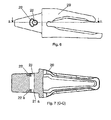
- Figure 8 shows a plan profile and sectional view of a cylindrical pin;
- Figure 9 shows a plan profile and sectional view of a frustoconical pin;
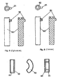
- Figure 10 shows three views of a tension member according to an embodiment of the invention and applicable in the assembly of Figure 1;
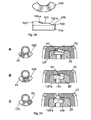
- Figure 11 shows three successive views showing the operation of a device according to an embodiment of the invention;
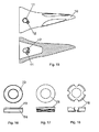
- Figure 12 shows a perspective view of a tooth-tooth bar assembly of a bucket of an excavating machine with a device according to an embodiment of the invention;
- Figure 13 shows a side view of the tooth bar of Figure 12;
- Figure 14 shows a sectional view of the tooth bar of Figure 13 according to D-D:
- Figure 15 shows a sectional view of the tooth and of the tooth of Figure 12;
- Figure 16 shows a tension member applicable in the assembly of Figure 12;
- Figure 17 shows a tension member applicable in the assembly of Figure 12;
- Figure 18 shows a tension member applicable in the assembly of Figure 12;
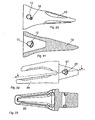
- Figure 19 shows a perspective view of a tooth-tooth bar assembly of a bucket of an excavating machine with a device according to an embodiment of the invention;
- Figure 20 shows a side view of the tooth of Figure 19;
- Figure 21 shows a sectional view of the tooth of Figure 20;
- Figure 22 shows a side view of the tooth bar of Figure 19;
- Figure 23 shows a sectional view of the tooth bar of Figure 22 according to E-E;
- Figure 24 shows three views of a tension member applicable to the assembly of Figure 19;
- Figure 25 shows three successive views showing the operation of a device according to the embodiment of the invention shown in Figure 19;
- Figure 26 shows a perspective view of a tooth-tooth bar assembly of a bucket of an excavating machine with a device according to an embodiment of the invention;
- Figure 27 shows a perspective view of a mounted tooth-tooth bar assembly of a bucket of an excavating machine with a device according to Figure 26;
- Figure 28 shows a tension member applicable in the assembly of Figure 26;
- Figure 29 shows three successive views showing the operation of a device according to the assembly of Figure 26;
- Figure 30 shows two views of a tension member according to an embodiment of the invention;
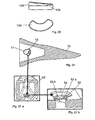
- Figure 31 shows a sectional view of a tooth according to an embodiment of the invention;
- Figure 31 a shows a detail of the tooth of Figure 13;
- Figure 31 b shows an enlarged detail of the tooth of Figure 13a;
- Figure 32 shows two views of a tension member according to an alternative embodiment of the invention;
- Figure 33 shows three successive views showing the operation of a device using the tension member of Figure 32;
- Figure 34 shows a perspective view of a tooth-tooth bar assembly of a bucket of an excavating machine with a device according to an embodiment of the invention;
- Figure 35 shows a plan, elevational and sectional view of a pin;
- Figure 36 shows a plan, elevational and sectional view of a pin;
- Figure 37 shows three successive views showing the operation of a device according to an embodiment of the invention with the pin of figure 35;
- Figure 38 shows a side view of a tooth bar according to an embodiment of the invention applicable with the pin of Figure 35 or Figure 36;
- Figure 39 shows three successive views showing the operation of a device according to an embodiment of the invention with the pin of Figure 36 and the tooth bar of Figure 38.
- Embodiments of the invention applied, by way of example, to the assembly and removal of a tooth in a tooth bar of a bucket of an excavating machine are described below, but it is clear that the device can be used for the removable attachment of another type of mechanical parts.
- In reference to figures 1 to 11, a tooth-
tooth bar assembly 1 comprises atooth 10, atooth bar 20, apin 30 and aresilient tension member 40, the latter formed by ametal member 43 located on aresilient member 44. - The
pin 30 is provided with a body, the shape of which is that of a surface of revolution, and of atransverse projection 31 constituting a retainer member for the pin itself. One of the ends of thepin 30 contains arecess 32 with the shape suitable for coupling a tool by means of which a rotational movement can be applied to the pin about its longitudinal axis. - The
tooth 10 is provided with ahole 11 with anotch 12 for being able to introduce thepin 30 with the projection orretainer member 31. It can also include ahole 11a with anotch 12a on the surface or side wall opposite to the previous one, such that it allows the introduction of the pin through either of the two sides. Thetooth bar 20 includes ahole 21 for thepin 30 and acavity 22 for housing thetension member 40. It is likewise possible to also include a hole 21a and a cavity 22a on the surface of the tooth bar opposite to the previous one. - With the pin mounted in the assembly, the
tension member 40 should not be loaded or significantly resiliently loaded, saidtension member 40 remaining between thecavity 22 and theretainer member 31.Said tension member 40 is a curved segment and has the function of hindering the backwards movement, possibly caused due to the vibrations occurring in the excavation process, of theretainer member 31 from its assembly position (position C in Figure 11) to its introduction or extraction position (position A in Figure 11). - The tooth-
tooth bar assembly 1 is mounted first by coupling thetooth 10 and thetooth bar 20 with thetension member 40 previously housed in thecavity 22 of thetooth bar 20, then by introducing the pin into the holes of the tooth and the housing of the tooth bar and, lastly, rotating the pin by means of a suitable tool until the assembly or lock position in which theretainer member 31 of thepin 30 remains trapped between the tooth and the tooth bar. Due to the shape of thehole 11 of thetooth 10, thepin 30 can only be introduced in the precise position in which theretainer member 31 passes through thenotch 12. - In this embodiment, shown in Figure 11 in three positions A, B and C, the
tension member 40 formed by themetal portion 43 andresilient portion 44 is planar and an inner surface of thetooth 10 is provided with two inclined surfaces 13a and 13b ending in aprojection 14. On the same inner surface of the tooth, next to inclined surface 13b, there is acavity 15 for housing theretainer member 31 of thepin 30 in its lock position (position C in Figure 11). - Inclined surface 13a presents a first slight ramp which does excessively obstruct the forward movement of the
retainer member 31 from position A to said lock position C, and a steep second ramp 13b making the backwards movement of the retainer member from position C to said unlock position A more difficult. Thetension member 40 is housed in thecavity 22 and cannot be displaced, but it can be compressed since it is resilient, and this compression allows the forward movement of theretainer member 31 along the inclined surfaces 13a and 13b, passing through the projection 14 (position B in Figure 11). Furthermore, as previously mentioned, when the pin is in its final lock position, thetension member 40 does not maintain a significant resilient compression load. - In order to remove the
tooth 10, thepin 30 is simply rotated from its lock position to the introduction or unlock position with enough force so that theretainer member 31 compresses thetension member 40 even more and overcomes the steep ramp of surface 13b, then all that remains is to easily extract the pin from the tooth bar and from the tooth. - In this embodiment, the movements of the
pin 10 are translational and rotational and the body of the pin will preferably be cylindrical (see Figure 8). The pin has two translational movements until its assembly position, therefore conferring greater security to the retainer device given that its extraction requires a translational movement in one direction and subsequently a translational movement in the direction opposite to the previous one, thus making the accidental removal of the pin, and therefore of the tooth while working, difficult. The pin in this embodiment is preferably cylindrical given that the spaces for the possible housing of dirt between the pin and the housing thereof in the tooth bar are limited to the outer surface of the pin. If the pin used in this embodiment were frustoconical, there could be problems in the extraction thereof since the dirt which is introduced while the device is working could prevent the translational movement of the pin as it fills up those spaces existing between the pin and the housing in the tooth bar, creating dirt wedges around the outer surface of the pin. - In another embodiment of the invention as shown in Figures 12 to 18, rather than being a curved segment, the tension member can be a
circular washer 70 made up of aresilient portion 74 and ametal portion 73. When the tooth and tooth bar are applied to hot-working operations, saidtension member 70 with a metal portion and another resilient portion may be replaced by a metal washer, such as aspring 76 orspring 75 for example. - In this embodiment, the movements of the
pin 30 are also axially rotational such that the body of the pin will preferably be cylindrical, since if it were frustoconical said translational movement would only be possible at the expense of a poor fitting of thepin 30 in thetooth 10 and thetooth bar 20. - In another embodiment represented in Figures 19 to 25, the
tension member 80 is provided with aplanar entry surface 87 and two inclined surfaces 85a and 85b, which end in aprojection 81, said inclined surfaces separating the initial introduction or unlocking position (corresponding to planar surface 87) of theretainer member 61 together with the pin 60 (position A in Figure 25) from its final assembly or lock position,planar surface 86 of the tension member 80 (position C in Figure 25). The assembly and removal process of this embodiment is similar to that of the previously explained embodiment, and in this embodiment, the lock position of thepin 60 is secure by virtue of the interaction between theresilient tension member 80,retainer member 61,planar surface 86 andsurface 22. In said Figure 25, it can be observed how thetension member 80 is compressed with respect to reference line R-R when the pin axially rotates and said tension member is compressed due to the action of theretainer member 61, without there being axial displacement of thepin 60. In these cases in which there is only a rotational and not axial movement of the pin, it is preferable for the pin to be frustoconical since during the unlocking operation, its being frustoconical facilitates its extraction, since the contact between the surface of the pin and of the housing is less and therefore should the gap between the pin and walls of the housing be full of dirt, the effort required to axially displace the pin will be less. Likewise, should the pin become deformed during the working of the retainer device, if said pin were cylindrical, rotation thereof would be more complicated since there would be greater contact between the pin and the housing in the tooth bar due to the constant section of the pin, however since it is frustoconical, the rotation will not be hindered due to there being less contact with the housing in the tooth bar. - In this embodiment, a
frustoconical pin 60 has been used (Figure 9), although as in all the explained embodiments, frustoconical and cylindrical pins may be used indistinctly, although evidently the use of one rather than the other will be more advantageous according to the embodiment. - In another embodiment of the invention represented in Figures 26 to 29, the
tension member 100, with ametal portion 103 and aresilient portion 104, preferably with a curved segment shape, is provided with two downwardly inclined surfaces 105a and 105b separated from one another by aplanar section 101 in itsmetal portion 103. There is also aplanar area 106 at the end of saidtension member 100. The operation is identical to that already described for the previous embodiments, but it allows different assembly positions in order to increase the pressure on theretainer member 61 of the preferablyfrustoconical pin 60 of thetooth 10. By means of this configuration, it is possible to displace the pin inwardly as thetooth 10 ortooth bar 20 becomes worn due to the effect of the shocks and vibrations generated between thetooth 10 andtooth bar 20. - Three positions A, B and C are represented in Figure 29 in which the axial rotation and axial translation displacement of the
pin 60 along themetal surface 103 of thetension member 100 is observed. - Another embodiment of the invention, represented in Figures 30 and 31, shares the same technical principle as the one described in Figures 26 to 29, with two downwardly inclined surfaces 53a and 53b, separated from one another by a
planar surface 54, and said surfaces located on the inner wall or surface of thetooth 10. In this embodiment, after theinclined surface 53 the inner wall or surface of thetooth 10 has anotherplanar surface 55 where the run of theretainer member 61 of thepin 60 ends, saidpin 60 preferably being frustoconical. Thetension member 130 used for this embodiment, formed by ametal portion 133 on aresilient portion 134, preferably with a curved segment shape, has its upper surface planar, straight and inclined, corresponding to the metal portion, with respect to its lower surface which is planar and straight, corresponding to its resilient portion. - Another embodiment is represented in Figures 32 and 33, having the same operating principle as all the embodiments and similar in its construction to the embodiment shown in Figures 26 to 29. In this variant the
tension member 90 has, as in the others, ametallic member 93 placed on top of aresilient portion 94, the upper surface of themetal portion 93 of the tension member having a firstplanar surface 97 followed by an inclined surface 95a, after which there is arranged a second inclined surface 95b and ending in a secondplanar surface 96. The second inclined surface 95b is almost perpendicular toplanar surfaces - This device facilitates the extraction of the pin from its housing given that when the disassembly tool is turned, the pin comes out due only to the effect of the tension member which pushes it outwards. The height difference between the first
planar surface 97 of thetension member 90 and the secondplanar surface 96 of saidtension member 90 is the run of the axial displacement of the pin, allowing the arrangement of part of the pin outside of its housing prior to the introduction of the pin in the housing. This device is preferably applicable in dredging systems. - In another embodiment shown in Figures 34 to 39, the
tension member pin retainer member rib tooth 10 or on the outer surface of thetooth bar 20. - Specifically, and in view of Figures 34, 35 and 37, the
tension member 113 is located on the lower portion of theretainer member 111 of thepin 110, locating the facing inclined surfaces 13a, 13b defining arib 14 on the inner surface of thetooth 10, ahousing 15 remaining for theretainer member 111 in its assembly position. In this device, thepin 110 carries out an axial rotation and translation displacement. - However in view of Figures 36, 38 and 39, if the
tension member 123 is located in the upper portion of theretainer member 121 of thepin 120, the facing inclined surfaces 127a, 127b defining arib 125 must be located on the outer surface of thetooth bar 20, preceded on both sides byplanar surfaces - Both configurations can be alternated according to the working requirements, being able to change the movements carried out by the pin.
- On the other hand, the specific shape of the inclined surfaces may be any shape suitable for facilitating the rotation of the pin from the unlocking position to the lock position and at the same time preventing the retainer member from being released from the lock position during normal working of the excavator. It is also possible to arrange more than two inclined surfaces if the embodiment so requires, mainly in those embodiments allowing several tightening positions between the tooth and tooth bar as the tooth bar becomes deformed.
- The invention has been described making reference to several specific embodiments, but a person skilled in the art could combine the different embodiments according to the application requirements and introduce variations and replace some members with other technically equivalent members, which will also be comprised within the scope of protection defined by the attached claims.
Claims (36)
- A removable device (1) for attaching two mechanical parts which comprises a pin (30, 60, 110, 120) removably locking a first female part (10) with respect to a second male part (20), a retainer member (31, 61, 111, 121) associated to the pin (30, 60, 110, 120) and a resiliently loaded tension member (40, 70, 75, 76, 80, 100, 90, 130, 113, 123), which cooperate to prevent the pin (30, 60, 110, 120) from coming out of its lock position, characterized by the fact that it comprises a surface with at least two planar or inclined surfaces (13a, 13b, 85a, 85b, 105a, 105b, 53a, 53b, 95a, 95b, 127a, 127b) such that when the retainer member (31, 61, 111, 121) rotates said retainer member (31, 61, 111, 121) runs along said inclined surfaces (13a, 13b, 85a, 85b, 105a, 105b, 53a, 53b, 95a, 95b, 127a, 127b) moving between at least two positions against the force exerted axially to the axis of the pin (30, 60, 110, 120) by said tension member (40, 70, 75, 76, 80, 100, 90, 130, 113, 123).
- A device according to claim 1, characterized by the fact that the inclined surfaces (85a, 85b, 105a, 105b, 95a, 95b) are formed on one face of the tension member (80, 100, 90).
- A device according to claim 1, characterized by the fact that the inclined surfaces (13a, 13b, 53a, 53b, 127a, 127b) are formed on one of said parts (10, 20) and on at least one of the contact surfaces between both parts (10, 20).
- A device according to claim 3, characterized by the fact that the same surface of said part (10, 20) containing inclined planes (13a, 13b) is provided with a cavity (15) housing the retainer member (31, 61, 111) of the pin (30, 60, 110) in its lock position.
- A device according to any of the previous claims, characterized by the fact that inclined planes (13a, 13b, 53a, 53b, 127a, 127b) form two facing ramps with a rib between both.
- A device according to claims 4 and 5, characterized by the fact that the tension member (40, 70, 75, 76) has its upper and lower surfaces planar, straight and parallel to one another.
- A device according to any of claims 1 to 4, characterized by the fact that inclined planes (105a, 105b, 53a, 53b) form at least two downwardly inclined ramps (105a, 105b, 53a, 53b) separated from one another by a planar section (101, 54).
- A device according to claims 4 and 7, characterized by the fact that the tension member (130) has its upper surface planar, straight and inclined with respect to its planar and straight lower surface.
- A device according to any of claims 1 to 4, characterized by the fact that inclined planes (95a, 95b) form at least two inclined ramps (95a, 95b), one after the other, one of them (95b) having a steeper slope than the other one (95a).
- A device according to any of the previous claims, characterized by the fact that the pin (30,60) has the shape of a surface of revolution.
- A device according to claim 10, characterized by the fact that the pin (60) is frustoconical.
- A device according to claim 11, characterized by the fact that the pin (30) is cylindrical.
- A device according to any of the previous claims, characterized by the fact that the pin has a circular section.
- A device according to any of the previous claims, characterized by the fact that the pin has an elliptical section.
- A device according to any of the previous claims, characterized by the fact that the retainer member (31, 61, 111, 121) constitutes a transverse projection of the pin (30, 60, 110, 120).
- A device according to claim 15, characterized by the fact that the retainer member (31, 61, 111, 121) is joined to the pin (30, 60, 110, 120).
- A device according to any of the previous claims, characterized by the fact that one of the ends of the pin (30, 60, 110, 120) has a coupling (32, 62, 112, 122) for a tool by means of which it is possible to apply a rotational movement to said pin about its longitudinal axis.
- A device according to any of claims 1 to 17, characterized by the fact that the tension member (40, 80, 100, 130, 90) is a curved segment.
- A device according to any of claims 1 to 17, characterized by the fact that the tension member (70,75, 76) is a simple circular washer.
- A device according to claims 18 and 19, characterized by the fact that the tension member is constituted only of an elastomeric material.
- A device according to claims 18 and 19, characterized by the fact that the tension member (40, 80, 70, 100, 90, 130, 113, 123) is constituted of a metal member (43, 83, 73, 103, 93, 133) arranged on a resilient member (44, 84, 74; 104, 94, 134).
- A device according to claim 19, characterized by the fact that the tension member (76) is a metal spring.
- A device according to claim 19, characterized by the fact that the tension member (75) is a metal spring.
- A device according to any of the previous claims, characterized by the fact that the tension member (113, 123) is mounted or built on the pin (110, 120).
- A device according to any of the previous claims, characterized by the fact that the male part (20) comprises a cavity (22) in at least one of its outer surfaces for housing the tension member (40, 70, 75, 76, 80, 100, 90, 130).
- A device according to any of the previous claims, characterized by the fact that the female part (10) comprises a cavity in at least one of its inner surfaces for housing the tension member.
- A device according to any of the previous claims, characterized by the fact that the female part (10) is provided with at least one hole (11) with a notch (12) for being able to introduce the pin (30, 60, 110, 120) with the projection or retainer member (31, 61, 111, 121).
- A device according to any of the previous claims, characterized by the fact that said female part (10) is a tooth and said male part (20) is a tooth bar.
- A female part for being coupled in a male part and having at least one hole for introducing a pin, characterized in that it has at least two inclined planes in at least one of its inner surfaces applicable to a retainer device according to claim 1.
- A female part according to claim 29, characterized by the fact that the same inner surface of the female part containing the inclined planes is provided with a cavity housing the retainer member of the pin in its lock position.
- A female part according to claims 29 and 30, characterized by the fact that the inclined planes form two facing ramps with a rib between them.
- A female part according to claim 29, characterized by the fact that the inclined planes form at least two downwardly inclined ramps separated from one another by a planar and straight section.
- A female part according to claim 29, characterized by the fact that said hole has a notch for introducing a retainer member associated to the pin.
- A female part according to claims 29 to 33, characterized by the fact that it is a tooth of the type coupled to a tooth bar.
- A male part for being coupled to a female part and having a housing inside for receiving a pin, characterized in that it has at least two inclined planes in at least one of its outer surfaces and is applicable to a retainer device according to claim 1.
- A male part according to claim 34, characterized by the fact that it is a tooth bar of the type coupled to a tooth.
Applications Claiming Priority (1)
| Application Number | Priority Date | Filing Date | Title |
|---|---|---|---|
| PCT/ES2004/000144 WO2005095720A1 (en) | 2004-03-30 | 2004-03-30 | Device for removably fixing two mechanical parts to one another |
Publications (2)
| Publication Number | Publication Date |
|---|---|
| EP1741842A1 true EP1741842A1 (en) | 2007-01-10 |
| EP1741842B1 EP1741842B1 (en) | 2010-09-29 |
Family
ID=35063823
Family Applications (1)
| Application Number | Title | Priority Date | Filing Date |
|---|---|---|---|
| EP04724300A Expired - Lifetime EP1741842B1 (en) | 2004-03-30 | 2004-03-30 | Device for removably fixing two mechanical parts to one another |
Country Status (14)
| Country | Link |
|---|---|
| US (3) | US7707755B2 (en) |
| EP (1) | EP1741842B1 (en) |
| JP (1) | JP4440302B2 (en) |
| CN (1) | CN1926288B (en) |
| AT (1) | ATE483072T1 (en) |
| AU (1) | AU2004318061C1 (en) |
| BR (1) | BRPI0418595B1 (en) |
| CA (1) | CA2555794C (en) |
| DE (1) | DE602004029401D1 (en) |
| DK (1) | DK1741842T3 (en) |
| ES (1) | ES2351424T3 (en) |
| NO (1) | NO338284B1 (en) |
| PT (1) | PT1741842E (en) |
| WO (1) | WO2005095720A1 (en) |
Cited By (1)
| Publication number | Priority date | Publication date | Assignee | Title |
|---|---|---|---|---|
| WO2020201418A1 (en) | 2019-04-03 | 2020-10-08 | Metalogenia Research & Technologies S.L. | Locking device for coupling a wear element to a support in an earth moving machine |
Families Citing this family (76)
| Publication number | Priority date | Publication date | Assignee | Title |
|---|---|---|---|---|
| CA2555794C (en) * | 2004-03-30 | 2012-09-25 | Metalogenia, S.A. | Device for removably fixing two mechanical parts to one another |
| JO3201B1 (en) | 2006-03-30 | 2018-03-08 | Esco Corp | Wear Assembly |
| WO2008116942A1 (en) * | 2007-03-28 | 2008-10-02 | Metalogenia, S.A. | Detachable fastening system between a male piece and a female piece, pin and female piece |
| AU2008207519B2 (en) * | 2007-08-23 | 2014-10-02 | Wearforce Pty Ltd | Shroud Assembly |
| US8127476B2 (en) * | 2008-12-19 | 2012-03-06 | Berkeley Forge & Tool, Inc. | Quick release screw connector for earth-moving equipment |
| CN101530956B (en) * | 2009-03-10 | 2010-12-08 | 国营江河化工厂 | Disassembling method of mixing paddle |
| US8261472B2 (en) | 2009-03-23 | 2012-09-11 | Black Cat Blades Ltd. | Retrofitted excavator tooth attachment |
| US7980011B2 (en) * | 2009-03-23 | 2011-07-19 | Black Cat Blades Ltd. | Fully stabilized excavator tooth attachment |
| BR122017028180B8 (en) * | 2009-03-23 | 2022-05-03 | Black Cat Blades Ltd | Attachment system for an excavator implement |
| AU2013211524B2 (en) * | 2009-10-29 | 2016-03-31 | Black Cat Wear Parts Ltd. | Retrofitted excavator tooth attachment |
| RU2546179C2 (en) * | 2009-12-11 | 2015-04-10 | Си-Кью-Эм-Эс ПТИ ЛТД | Excavator wearing element lock assembly |
| USRE45710E1 (en) * | 2009-12-11 | 2015-10-06 | CQMS Pty Limited | Locking pin assembly for an excavator wear member |
| USD634605S1 (en) * | 2010-05-24 | 2011-03-22 | Cqms Pty Ltd | Locking pin assembly for an excavator wear member |
| JP5055464B2 (en) * | 2010-03-31 | 2012-10-24 | 株式会社小松製作所 | Working machine and mounting pin assembly |
| PE20130832A1 (en) * | 2010-04-30 | 2013-08-17 | Bradken Resources Pty Ltd | WEAR SET |
| PT2466159E (en) * | 2010-12-15 | 2013-11-19 | Agustawestland Spa | Fastening assembly |
| CN103842592A (en) * | 2011-06-02 | 2014-06-04 | 布莱肯资源私人有限公司 | Lock |
| US9057176B2 (en) * | 2011-06-28 | 2015-06-16 | Caterpillar Inc. | Retention system for a ground-engaging tool |
| UA108940C2 (en) * | 2011-07-05 | 2015-06-25 | A holding device, a holding system between the gripping component and the covered component, the gripping component and the gripping and storing component | |
| JO3726B1 (en) * | 2011-07-14 | 2021-01-31 | Esco Group Llc | Wear assembly |
| AU2011375828B2 (en) | 2011-08-26 | 2014-10-23 | Black Cat Wear Parts Ltd. | Protected wear assembly for material handling apparatus |
| US8890672B2 (en) * | 2011-08-29 | 2014-11-18 | Harnischfeger Technologies, Inc. | Metal tooth detection and locating |
| FR2979647B1 (en) * | 2011-09-01 | 2013-10-04 | Afe Metal | MECHANICAL SYSTEM COMPRISING A DEVICE FOR CONNECTION BETWEEN A WEAR PIECE AND ITS SUPPORT, PUBLIC WORKS MACHINE BUCKET AND METHOD OF IMPLEMENTING SUCH A SYSTEM |
| US10011977B2 (en) * | 2011-09-08 | 2018-07-03 | Miguel Guimaraes | Lock assembly for an excavator wear member |
| US8943717B2 (en) | 2011-10-08 | 2015-02-03 | Caterpillar Inc. | Implement tooth assembly with tip and adapter |
| US9062436B2 (en) | 2011-10-07 | 2015-06-23 | Caterpillar Inc. | Implement tooth assembly with tip and adapter |
| US9057177B2 (en) | 2011-10-08 | 2015-06-16 | Caterpillar Inc. | Implement tooth assembly with tip and adapter |
| US8943716B2 (en) | 2011-10-10 | 2015-02-03 | Caterpillar Inc. | Implement tooth assembly with tip and adapter |
| BR122020005546B1 (en) | 2011-11-23 | 2021-08-10 | Esco Group Llc | FIXING LOCK FOR FIXING A WEAR MEMBER TO AN EARTH COUPLING EQUIPMENT |
| AU2011253753B2 (en) * | 2011-11-30 | 2014-10-09 | 2Mt Mining Products Pty Ltd | Dragline pin locking device |
| IN2014KN01273A (en) * | 2011-12-08 | 2015-10-16 | Cqms Pty Ltd | |
| CN103174184B (en) * | 2011-12-20 | 2015-06-03 | 斗山工程机械(中国)有限公司 | Excavator and bucket tooth connection structure thereof |
| PT2620557T (en) * | 2012-01-24 | 2022-02-01 | Javier Bartolome Rodriguez | Wear assembly for machinery |
| USD743446S1 (en) * | 2012-06-15 | 2015-11-17 | Belltec Industries, Inc. | Coupler |
| CN103813618A (en) * | 2012-11-14 | 2014-05-21 | 鸿富锦精密工业(深圳)有限公司 | base fixture |
| CA2805398A1 (en) * | 2013-02-08 | 2014-08-08 | Quality Chain Canada Ulc | Bucket tooth locking pin |
| US9074351B2 (en) * | 2013-03-15 | 2015-07-07 | Caterpillar Inc. | Retainer systems for ground engaging tools |
| US9309651B2 (en) | 2013-03-15 | 2016-04-12 | Caterpillar Inc. | Retainer systems for ground engaging tools |
| WO2014153591A1 (en) | 2013-03-25 | 2014-10-02 | Keech Castings Australia Pty Limited | Lock assembly |
| AU2013204873B2 (en) * | 2013-04-12 | 2016-04-28 | Bradken Resources Pty Limited | Excavation Tooth Assembly |
| AU2013204854B2 (en) | 2013-04-12 | 2016-04-21 | Bradken Resources Pty Limited | Excavation Tooth Assembly |
| AU2013204892B2 (en) * | 2013-04-12 | 2016-04-28 | Bradken Resources Pty Limited | Excavation Tooth Assembly |
| CN103243773B (en) * | 2013-05-10 | 2015-12-30 | 宁波市鄞州精铸五金厂 | A kind of excavator bucket teeth |
| US20150013197A1 (en) * | 2013-07-12 | 2015-01-15 | Caterpillar Inc. | Wear collar for tool retention system |
| US9157217B2 (en) | 2013-07-23 | 2015-10-13 | Caterpillar Inc. | Tool retention system having cam-driven keys |
| US9139984B2 (en) * | 2013-07-30 | 2015-09-22 | Caterpillar Inc. | Retainer systems for ground engaging tools |
| US9518380B2 (en) | 2014-01-15 | 2016-12-13 | Caterpillar Inc. | Tool retention system |
| WO2016019193A2 (en) * | 2014-07-30 | 2016-02-04 | Itr America Llc | Cutting link for mining chain and mining pin retention system |
| CN104563194B (en) * | 2014-11-29 | 2017-01-18 | 宁波市鄞州精铸五金厂 | Excavator bucket tooth with improved structure |
| JP6454780B2 (en) | 2015-02-13 | 2019-01-16 | ブラック、キャット、ブレイズ、リミテッドBlack Cat Blades Ltd. | Wear materials for drilling equipment |
| US9611625B2 (en) | 2015-05-22 | 2017-04-04 | Harnischfeger Technologies, Inc. | Industrial machine component detection and performance control |
| US9670648B2 (en) | 2015-08-10 | 2017-06-06 | Caterpillar Inc. | Replaceable tip systems for a tine |
| AU2016354542B2 (en) | 2015-11-12 | 2019-03-07 | Joy Global Surface Mining Inc | Methods and systems for detecting heavy machine wear |
| USD812108S1 (en) | 2016-03-02 | 2018-03-06 | Belltec Industries, Inc. | Hex coupler |
| US10508418B2 (en) | 2016-05-13 | 2019-12-17 | Hensley Industries, Inc. | Stabilizing features in a wear member assembly |
| US10544568B2 (en) | 2016-05-16 | 2020-01-28 | Caterpillar Inc. | Retainer sleeve for ground engaging tools |
| CN106703111B (en) * | 2017-01-23 | 2022-10-21 | 宁波禾顺新材料有限公司 | Connector for wear assembly of excavating equipment and wear assembly |
| KR101817064B1 (en) * | 2017-08-09 | 2018-01-10 | 성보공업주식회사 | A bucket tooth of excavator |
| US11846187B2 (en) | 2017-08-30 | 2023-12-19 | Itr America, Llc | Mining pin retention system |
| KR101911513B1 (en) * | 2017-12-29 | 2018-10-24 | 성보공업주식회사 | Tooth for bucket of excavator |
| CN108505580B (en) * | 2018-03-27 | 2023-12-26 | 浙江澳德耐磨零部件有限公司 | Tooth head structure for excavator and dredging machine |
| USD918965S1 (en) | 2018-06-19 | 2021-05-11 | Hensley Industries, Inc. | Ground engaging wear member |
| US11492784B2 (en) | 2019-04-15 | 2022-11-08 | Hensley Industries, Inc. | Position-biased locking pin assembly for a ground engaging wear member |
| US12650007B2 (en) | 2019-07-22 | 2026-06-09 | 2Mt Mining Products Pty Ltd. | Retainer systems |
| CN111549837A (en) * | 2020-06-04 | 2020-08-18 | 上海三一重机股份有限公司 | Bucket tooth, bucket and excavator |
| US12509861B2 (en) * | 2020-07-17 | 2025-12-30 | Metalogenia Research & Technologies S.L. | Adapter and wear element with a pin arranged at a low stress point |
| USD973108S1 (en) * | 2020-12-04 | 2022-12-20 | Sungbo Industrial Co., Ltd. | Part for excavator bucket |
| USD973107S1 (en) * | 2020-12-04 | 2022-12-20 | Sungbo Industrial Co., Ltd. | Part for excavator bucket |
| US11761177B2 (en) | 2021-02-12 | 2023-09-19 | Caterpillar Inc. | Anti-tipping features for a retaining mechanism |
| USD978924S1 (en) * | 2021-12-14 | 2023-02-21 | Metalogenia Research & Technologies S.L. | Excavator bucket tooth |
| USD978925S1 (en) * | 2021-12-14 | 2023-02-21 | Metalogenia Research & Technologies S.L. | Excavator bucket tooth adapter |
| AU2023266401B2 (en) * | 2022-05-11 | 2025-10-09 | 2Mt Mining Products Pty Ltd | Retainer systems |
| CA217721S (en) * | 2022-06-09 | 2024-08-13 | Bradken Resources Pty Ltd | Wear member of a wear assembly |
| CA217723S (en) * | 2022-06-09 | 2024-08-13 | Bradken Resources Pty Ltd | Wear member of a wear assembly |
| US20240011257A1 (en) * | 2022-07-08 | 2024-01-11 | Caterpillar Inc. | Tip and adapter coupling system |
| US20250027298A1 (en) * | 2023-07-21 | 2025-01-23 | Caterpillar Inc. | Tool retention system with external locking mechansim |
Family Cites Families (19)
| Publication number | Priority date | Publication date | Assignee | Title |
|---|---|---|---|---|
| US2373722A (en) * | 1942-02-20 | 1945-04-17 | Opel Fritz Von | Fastening device |
| GB1180962A (en) * | 1967-06-07 | 1970-02-11 | Dzus Fastener Europe | Improvements in Quick Release Fasteners. |
| US4903420A (en) * | 1988-10-20 | 1990-02-27 | Esco Corporation | Mining tooth point |
| US4918843A (en) * | 1989-02-21 | 1990-04-24 | Caterpillar Inc. | Ground engaging tool |
| CN2072547U (en) * | 1990-08-06 | 1991-03-06 | 谢立 | Fast exchanging sleeving bucket tooth |
| US5205057A (en) * | 1991-09-10 | 1993-04-27 | Caterpillar Inc. | Retaining mechanism for a tooth assembly |
| US5368427A (en) * | 1993-02-08 | 1994-11-29 | General Motors Corporation | Quarter turn fastener |
| US5435084A (en) * | 1994-02-17 | 1995-07-25 | Harnischfeger Corporation | Apparatus and method for attaching a digging tooth tip |
| US5561925A (en) * | 1995-07-25 | 1996-10-08 | Caterpillar Inc. | Tooth assembly and retaining mechanism |
| US5718070A (en) * | 1995-11-13 | 1998-02-17 | Gh Hensley Industries, Inc. | Self-adjusting tooth/adapter connection system for material displacement apparatus |
| US5983534A (en) | 1997-09-17 | 1999-11-16 | G. H. Hensley Industries, Inc. | Rotary lock system for excavating tooth/adapter assembly |
| US5987787A (en) * | 1998-02-11 | 1999-11-23 | Wright Equipment Company (Proprietary) Limited | Ground engaging tool components |
| US5956874A (en) * | 1998-05-07 | 1999-09-28 | Columbia Steel Casting Co., Inc. | Tooth assembly and lock system |
| US6108950A (en) * | 1999-03-08 | 2000-08-29 | Gh Hensley Industries, Inc. | Self-adjusting tooth/adapter connection system for material displacement apparatus |
| ES2158805B1 (en) * | 1999-10-01 | 2002-04-01 | Metalogenia Sa | IMPROVEMENTS IN THE COUPLINGS FOR MACHINE TEETH FOR GROUND MOVEMENT. |
| WO2004027272A2 (en) * | 2002-09-19 | 2004-04-01 | Esco Corporation | Coupling arrangement |
| US6826855B2 (en) * | 2002-11-04 | 2004-12-07 | Hensley Industries, Inc. | Excavating tooth point/adapter assembly with rotatably lockable connector structure |
| US7162818B2 (en) * | 2003-08-04 | 2007-01-16 | Hensley Industries, Inc. | Connector pin assembly and associated apparatus |
| CA2555794C (en) * | 2004-03-30 | 2012-09-25 | Metalogenia, S.A. | Device for removably fixing two mechanical parts to one another |
-
2004
- 2004-03-30 CA CA2555794A patent/CA2555794C/en not_active Expired - Lifetime
- 2004-03-30 DK DK04724300.1T patent/DK1741842T3/en active
- 2004-03-30 ES ES04724300T patent/ES2351424T3/en not_active Expired - Lifetime
- 2004-03-30 JP JP2007505566A patent/JP4440302B2/en not_active Expired - Lifetime
- 2004-03-30 DE DE602004029401T patent/DE602004029401D1/en not_active Expired - Lifetime
- 2004-03-30 CN CN2004800426117A patent/CN1926288B/en not_active Expired - Lifetime
- 2004-03-30 AU AU2004318061A patent/AU2004318061C1/en not_active Expired
- 2004-03-30 AT AT04724300T patent/ATE483072T1/en active
- 2004-03-30 PT PT04724300T patent/PT1741842E/en unknown
- 2004-03-30 EP EP04724300A patent/EP1741842B1/en not_active Expired - Lifetime
- 2004-03-30 BR BRPI0418595-1A patent/BRPI0418595B1/en not_active IP Right Cessation
- 2004-03-30 WO PCT/ES2004/000144 patent/WO2005095720A1/en not_active Ceased
- 2004-03-30 US US11/547,392 patent/US7707755B2/en not_active Expired - Lifetime
-
2006
- 2006-08-07 NO NO20063578A patent/NO338284B1/en unknown
-
2010
- 2010-03-15 US US12/724,322 patent/US9033610B2/en not_active Expired - Lifetime
-
2015
- 2015-03-30 US US14/673,191 patent/US10208460B2/en not_active Expired - Lifetime
Non-Patent Citations (1)
| Title |
|---|
| See references of WO2005095720A1 * |
Cited By (2)
| Publication number | Priority date | Publication date | Assignee | Title |
|---|---|---|---|---|
| WO2020201418A1 (en) | 2019-04-03 | 2020-10-08 | Metalogenia Research & Technologies S.L. | Locking device for coupling a wear element to a support in an earth moving machine |
| WO2020201587A1 (en) | 2019-04-03 | 2020-10-08 | Metalogenia Research & Technologies S.L. | Locking device for attaching a wear element to a support in an earth-moving machine |
Also Published As
| Publication number | Publication date |
|---|---|
| ATE483072T1 (en) | 2010-10-15 |
| CN1926288B (en) | 2010-07-07 |
| US20070209189A1 (en) | 2007-09-13 |
| US9033610B2 (en) | 2015-05-19 |
| NO338284B1 (en) | 2016-08-08 |
| US7707755B2 (en) | 2010-05-04 |
| AU2004318061A1 (en) | 2005-10-13 |
| CN1926288A (en) | 2007-03-07 |
| US10208460B2 (en) | 2019-02-19 |
| EP1741842B1 (en) | 2010-09-29 |
| DE602004029401D1 (en) | 2010-11-11 |
| AU2004318061C1 (en) | 2015-02-12 |
| ES2351424T3 (en) | 2011-02-04 |
| CA2555794C (en) | 2012-09-25 |
| JP2007530838A (en) | 2007-11-01 |
| JP4440302B2 (en) | 2010-03-24 |
| NO20063578L (en) | 2006-09-25 |
| AU2004318061B2 (en) | 2010-07-08 |
| WO2005095720A1 (en) | 2005-10-13 |
| CA2555794A1 (en) | 2005-10-13 |
| DK1741842T3 (en) | 2010-12-20 |
| BRPI0418595B1 (en) | 2015-07-07 |
| US20100170119A1 (en) | 2010-07-08 |
| BRPI0418595A (en) | 2007-06-26 |
| US20150275485A1 (en) | 2015-10-01 |
| PT1741842E (en) | 2010-12-07 |
Similar Documents
| Publication | Publication Date | Title |
|---|---|---|
| EP1741842B1 (en) | Device for removably fixing two mechanical parts to one another | |
| US7926207B2 (en) | Wear assembly and components thereof, which is intended for machines that are used to move materials such as earth and stones | |
| US9512599B2 (en) | Retention device for male and female components in excavator machines | |
| US8555532B2 (en) | Detachable fastening system between a male piece and a female piece, pin and female piece | |
| CN102308050B (en) | Connection system and parts thereof for connecting wear elements and adapters of excavators and similar machines | |
| ZA200608905B (en) | Device for removably fixing two mechanical parts to one another | |
| EP4324989B1 (en) | Pin for coupling between a wear element and a support of an earth-moving machine and coupling system | |
| KR101067185B1 (en) | Removal device for attaching two mechanical parts | |
| MXPA06008830A (en) | Device for removably fixing two mechanical parts to one another |
Legal Events
| Date | Code | Title | Description |
|---|---|---|---|
| PUAI | Public reference made under article 153(3) epc to a published international application that has entered the european phase |
Free format text: ORIGINAL CODE: 0009012 |
|
| 17P | Request for examination filed |
Effective date: 20061026 |
|
| AK | Designated contracting states |
Kind code of ref document: A1 Designated state(s): AT BE BG CH CY CZ DE DK EE ES FI FR GB GR HU IE IT LI LU MC NL PL PT RO SE SI SK TR |
|
| DAX | Request for extension of the european patent (deleted) | ||
| 17Q | First examination report despatched |
Effective date: 20090217 |
|
| GRAP | Despatch of communication of intention to grant a patent |
Free format text: ORIGINAL CODE: EPIDOSNIGR1 |
|
| GRAC | Information related to communication of intention to grant a patent modified |
Free format text: ORIGINAL CODE: EPIDOSCIGR1 |
|
| GRAS | Grant fee paid |
Free format text: ORIGINAL CODE: EPIDOSNIGR3 |
|
| GRAA | (expected) grant |
Free format text: ORIGINAL CODE: 0009210 |
|
| AK | Designated contracting states |
Kind code of ref document: B1 Designated state(s): AT BE BG CH CY CZ DE DK EE ES FI FR GB GR HU IE IT LI LU MC NL PL PT RO SE SI SK TR |
|
| REG | Reference to a national code |
Ref country code: GB Ref legal event code: FG4D |
|
| REG | Reference to a national code |
Ref country code: CH Ref legal event code: EP |
|
| REG | Reference to a national code |
Ref country code: IE Ref legal event code: FG4D |
|
| REF | Corresponds to: |
Ref document number: 602004029401 Country of ref document: DE Date of ref document: 20101111 Kind code of ref document: P |
|
| REG | Reference to a national code |
Ref country code: RO Ref legal event code: EPE |
|
| REG | Reference to a national code |
Ref country code: PT Ref legal event code: SC4A Free format text: AVAILABILITY OF NATIONAL TRANSLATION Effective date: 20101130 |
|
| REG | Reference to a national code |
Ref country code: DK Ref legal event code: T3 |
|
| REG | Reference to a national code |
Ref country code: SE Ref legal event code: TRGR |
|
| REG | Reference to a national code |
Ref country code: NL Ref legal event code: T3 |
|
| REG | Reference to a national code |
Ref country code: ES Ref legal event code: FG2A Effective date: 20110125 |
|
| PG25 | Lapsed in a contracting state [announced via postgrant information from national office to epo] |
Ref country code: SI Free format text: LAPSE BECAUSE OF FAILURE TO SUBMIT A TRANSLATION OF THE DESCRIPTION OR TO PAY THE FEE WITHIN THE PRESCRIBED TIME-LIMIT Effective date: 20100929 |
|
| REG | Reference to a national code |
Ref country code: HU Ref legal event code: AG4A Ref document number: E009770 Country of ref document: HU |
|
| PG25 | Lapsed in a contracting state [announced via postgrant information from national office to epo] |
Ref country code: SK Free format text: LAPSE BECAUSE OF FAILURE TO SUBMIT A TRANSLATION OF THE DESCRIPTION OR TO PAY THE FEE WITHIN THE PRESCRIBED TIME-LIMIT Effective date: 20100929 Ref country code: EE Free format text: LAPSE BECAUSE OF FAILURE TO SUBMIT A TRANSLATION OF THE DESCRIPTION OR TO PAY THE FEE WITHIN THE PRESCRIBED TIME-LIMIT Effective date: 20100929 |
|
| PLBE | No opposition filed within time limit |
Free format text: ORIGINAL CODE: 0009261 |
|
| STAA | Information on the status of an ep patent application or granted ep patent |
Free format text: STATUS: NO OPPOSITION FILED WITHIN TIME LIMIT |
|
| PG25 | Lapsed in a contracting state [announced via postgrant information from national office to epo] |
Ref country code: PL Free format text: LAPSE BECAUSE OF FAILURE TO SUBMIT A TRANSLATION OF THE DESCRIPTION OR TO PAY THE FEE WITHIN THE PRESCRIBED TIME-LIMIT Effective date: 20100929 |
|
| 26N | No opposition filed |
Effective date: 20110630 |
|
| REG | Reference to a national code |
Ref country code: DE Ref legal event code: R097 Ref document number: 602004029401 Country of ref document: DE Effective date: 20110630 |
|
| PG25 | Lapsed in a contracting state [announced via postgrant information from national office to epo] |
Ref country code: MC Free format text: LAPSE BECAUSE OF NON-PAYMENT OF DUE FEES Effective date: 20110331 |
|
| REG | Reference to a national code |
Ref country code: CH Ref legal event code: PL |
|
| REG | Reference to a national code |
Ref country code: IE Ref legal event code: MM4A |
|
| PG25 | Lapsed in a contracting state [announced via postgrant information from national office to epo] |
Ref country code: IE Free format text: LAPSE BECAUSE OF NON-PAYMENT OF DUE FEES Effective date: 20110330 Ref country code: CH Free format text: LAPSE BECAUSE OF NON-PAYMENT OF DUE FEES Effective date: 20110331 Ref country code: LI Free format text: LAPSE BECAUSE OF NON-PAYMENT OF DUE FEES Effective date: 20110331 |
|
| PG25 | Lapsed in a contracting state [announced via postgrant information from national office to epo] |
Ref country code: LU Free format text: LAPSE BECAUSE OF NON-PAYMENT OF DUE FEES Effective date: 20110330 Ref country code: CY Free format text: LAPSE BECAUSE OF FAILURE TO SUBMIT A TRANSLATION OF THE DESCRIPTION OR TO PAY THE FEE WITHIN THE PRESCRIBED TIME-LIMIT Effective date: 20100929 |
|
| REG | Reference to a national code |
Ref country code: GR Ref legal event code: EP Ref document number: 20100403036 Country of ref document: GR Effective date: 20110119 |
|
| REG | Reference to a national code |
Ref country code: FR Ref legal event code: PLFP Year of fee payment: 13 |
|
| REG | Reference to a national code |
Ref country code: FR Ref legal event code: PLFP Year of fee payment: 14 |
|
| REG | Reference to a national code |
Ref country code: FR Ref legal event code: PLFP Year of fee payment: 15 |
|
| PGFP | Annual fee paid to national office [announced via postgrant information from national office to epo] |
Ref country code: RO Payment date: 20230306 Year of fee payment: 20 Ref country code: FR Payment date: 20230327 Year of fee payment: 20 Ref country code: FI Payment date: 20230327 Year of fee payment: 20 Ref country code: DK Payment date: 20230329 Year of fee payment: 20 Ref country code: CZ Payment date: 20230307 Year of fee payment: 20 Ref country code: BG Payment date: 20230322 Year of fee payment: 20 Ref country code: AT Payment date: 20230303 Year of fee payment: 20 |
|
| PGFP | Annual fee paid to national office [announced via postgrant information from national office to epo] |
Ref country code: TR Payment date: 20230316 Year of fee payment: 20 Ref country code: SE Payment date: 20230315 Year of fee payment: 20 Ref country code: PT Payment date: 20230310 Year of fee payment: 20 Ref country code: IT Payment date: 20230321 Year of fee payment: 20 Ref country code: HU Payment date: 20230310 Year of fee payment: 20 Ref country code: GR Payment date: 20230331 Year of fee payment: 20 Ref country code: GB Payment date: 20230327 Year of fee payment: 20 Ref country code: DE Payment date: 20230329 Year of fee payment: 20 Ref country code: BE Payment date: 20230327 Year of fee payment: 20 |
|
| P01 | Opt-out of the competence of the unified patent court (upc) registered |
Effective date: 20230516 |
|
| PGFP | Annual fee paid to national office [announced via postgrant information from national office to epo] |
Ref country code: NL Payment date: 20230326 Year of fee payment: 20 |
|
| PGFP | Annual fee paid to national office [announced via postgrant information from national office to epo] |
Ref country code: ES Payment date: 20230403 Year of fee payment: 20 |
|
| REG | Reference to a national code |
Ref country code: DE Ref legal event code: R071 Ref document number: 602004029401 Country of ref document: DE |
|
| REG | Reference to a national code |
Ref country code: DK Ref legal event code: EUP Expiry date: 20240330 |
|
| REG | Reference to a national code |
Ref country code: NL Ref legal event code: MK Effective date: 20240329 |
|
| REG | Reference to a national code |
Ref country code: BE Ref legal event code: MK Effective date: 20240330 |
|
| REG | Reference to a national code |
Ref country code: ES Ref legal event code: FD2A Effective date: 20240405 |
|
| PG25 | Lapsed in a contracting state [announced via postgrant information from national office to epo] |
Ref country code: ES Free format text: LAPSE BECAUSE OF EXPIRATION OF PROTECTION Effective date: 20240331 |
|
| REG | Reference to a national code |
Ref country code: GB Ref legal event code: PE20 Expiry date: 20240329 |
|
| PG25 | Lapsed in a contracting state [announced via postgrant information from national office to epo] |
Ref country code: ES Free format text: LAPSE BECAUSE OF EXPIRATION OF PROTECTION Effective date: 20240331 Ref country code: CZ Free format text: LAPSE BECAUSE OF EXPIRATION OF PROTECTION Effective date: 20240330 Ref country code: GB Free format text: LAPSE BECAUSE OF EXPIRATION OF PROTECTION Effective date: 20240329 |
|
| REG | Reference to a national code |
Ref country code: SE Ref legal event code: EUG |
|
| REG | Reference to a national code |
Ref country code: AT Ref legal event code: MK07 Ref document number: 483072 Country of ref document: AT Kind code of ref document: T Effective date: 20240330 |
|
| PG25 | Lapsed in a contracting state [announced via postgrant information from national office to epo] |
Ref country code: PT Free format text: LAPSE BECAUSE OF EXPIRATION OF PROTECTION Effective date: 20240410 |
|
| PG25 | Lapsed in a contracting state [announced via postgrant information from national office to epo] |
Ref country code: PT Free format text: LAPSE BECAUSE OF EXPIRATION OF PROTECTION Effective date: 20240410 |