EP1741823B1 - Device to regulate the flow of steam in a domestic electrical appliance - Google Patents
Device to regulate the flow of steam in a domestic electrical appliance Download PDFInfo
- Publication number
- EP1741823B1 EP1741823B1 EP06116510A EP06116510A EP1741823B1 EP 1741823 B1 EP1741823 B1 EP 1741823B1 EP 06116510 A EP06116510 A EP 06116510A EP 06116510 A EP06116510 A EP 06116510A EP 1741823 B1 EP1741823 B1 EP 1741823B1
- Authority
- EP
- European Patent Office
- Prior art keywords
- steam
- pressure
- pipe
- drive element
- pressure element
- Prior art date
- Legal status (The legal status is an assumption and is not a legal conclusion. Google has not performed a legal analysis and makes no representation as to the accuracy of the status listed.)
- Expired - Lifetime
Links
Images


Classifications
-
- F—MECHANICAL ENGINEERING; LIGHTING; HEATING; WEAPONS; BLASTING
- F16—ENGINEERING ELEMENTS AND UNITS; GENERAL MEASURES FOR PRODUCING AND MAINTAINING EFFECTIVE FUNCTIONING OF MACHINES OR INSTALLATIONS; THERMAL INSULATION IN GENERAL
- F16K—VALVES; TAPS; COCKS; ACTUATING-FLOATS; DEVICES FOR VENTING OR AERATING
- F16K7/00—Diaphragm valves or cut-off apparatus, e.g. with a member deformed, but not moved bodily, to close the passage ; Pinch valves
- F16K7/02—Diaphragm valves or cut-off apparatus, e.g. with a member deformed, but not moved bodily, to close the passage ; Pinch valves with tubular diaphragm
- F16K7/04—Diaphragm valves or cut-off apparatus, e.g. with a member deformed, but not moved bodily, to close the passage ; Pinch valves with tubular diaphragm constrictable by external radial force
- F16K7/06—Diaphragm valves or cut-off apparatus, e.g. with a member deformed, but not moved bodily, to close the passage ; Pinch valves with tubular diaphragm constrictable by external radial force by means of a screw-spindle, cam, or other mechanical means
-
- D—TEXTILES; PAPER
- D06—TREATMENT OF TEXTILES OR THE LIKE; LAUNDERING; FLEXIBLE MATERIALS NOT OTHERWISE PROVIDED FOR
- D06F—LAUNDERING, DRYING, IRONING, PRESSING OR FOLDING TEXTILE ARTICLES
- D06F75/00—Hand irons
- D06F75/08—Hand irons internally heated by electricity
- D06F75/10—Hand irons internally heated by electricity with means for supplying steam to the article being ironed
- D06F75/12—Hand irons internally heated by electricity with means for supplying steam to the article being ironed the steam being produced from water supplied to the iron from an external source
-
- D—TEXTILES; PAPER
- D06—TREATMENT OF TEXTILES OR THE LIKE; LAUNDERING; FLEXIBLE MATERIALS NOT OTHERWISE PROVIDED FOR
- D06F—LAUNDERING, DRYING, IRONING, PRESSING OR FOLDING TEXTILE ARTICLES
- D06F75/00—Hand irons
- D06F75/08—Hand irons internally heated by electricity
- D06F75/10—Hand irons internally heated by electricity with means for supplying steam to the article being ironed
- D06F75/20—Arrangements for discharging the steam to the article being ironed
Definitions
- the present invention concerns a device to regulate the flow of steam in a domestic electrical appliance, such as for example a steam iron, or a steam cleaning machine.
- a device is known, for example from the European patent EP-B-0849521 , able to control the flow of steam generated by a boiler and conveyed by means of a pipe to a steam iron.
- the known device comprises a pressure element disposed in contact with a segment of pipe and connected to a drive element, disposed outside and free to rotate on a longitudinal axis X.
- the known device then transforms the rotational movement of the drive element into an axial movement of the pressure element, which thus exerts a variable pressure on the pipe, so as to regulate the quantity of steam that flows through the pipe.
- the known device however, has the disadvantage that it has a rather limited range of values for regulating the steam delivery.
- One purpose of the present invention is to achieve a device that allows to regulate the flow of steam in a domestic electrical appliance in a gradual manner, with a high degree of precision and with a wide regulation range.
- Another purpose of the present invention is to achieve a device which also allows to accommodate inside it means to command other functions of the domestic electrical appliance, such as for example switching it on or off.
- the Applicant has devised, tested and embodied the present invention to overcome the shortcomings of the state of the art and to obtain these and other purposes and advantages.
- a device is able to be used to regulate the flow of steam in a domestic electrical appliance, of the type having steam generation means, for example a steam iron or a cleaning machine, and a pipe to convey the steam from said generation means to the means that uses the steam.
- steam generation means for example a steam iron or a cleaning machine
- the pipe is made, at least for a segment, of elastically deformable material, such as for example rubber or other equivalent material.
- the device according to the present invention comprises at least a pressure element which is connected to an external drive element, which is free to rotate on a longitudinal axis X, and is able to exert a selectively variable pressure on the pipe, in order to regulate the quantity of steam that flows through said pipe.
- the drive element comprises a thrust surface disposed in contact with a mating surface of the pressure element.
- the thrust surface lies on a plane P inclined by a determinate angle ⁇ with respect to another plane P1 substantially orthogonal to the longitudinal axis X, in such a manner that the rotation of the external drive element determines a variation in the pressure exerted by the pressure element on the pipe.
- the invention allows to effect a regulation of the flow of steam, transforming the movement of rotation of the drive element into an oscillatory movement of the pressure element associated therewith.
- the oscillation of the pressure element occurs with respect to a point, or a plurality of points, determined by the intersection between the longitudinal axis X of the drive element and the longitudinal axis Y of the pressure element.
- the delivery of the steam can be regulated gradually, with great accuracy and in a wide range of values defined by the angle of rotation of the drive element.
- the pressure element comprises contact means, for example protrusions, teeth cooperating with the outer surface of the pipe and able to vary at least its cross section.
- the device also comprises housing means able to house at least said segment of pipe, the pressure element and the external drive element.
- Said means defines a seating able to contain, in the same integrated structure with the pressure element and the external drive element, means to command at least the steam generation means.
- the drive element has a size such as to allow it to rotate easily, with reduced drive force.
- a device 10 according to the present invention can be used in a domestic electrical appliance, such as for example an iron 11 connected to a boiler 14, which is contained in a unit, or casing, separated from the iron 11 itself, in order to regulate the flow of steam from the latter.
- a domestic electrical appliance such as for example an iron 11 connected to a boiler 14, which is contained in a unit, or casing, separated from the iron 11 itself, in order to regulate the flow of steam from the latter.
- the device 10 comprises a support 12, shown in fig. 2 , having a shape that adapts to the aesthetics of the unit, and positioned on the front surface of the unit containing the boiler 14.
- a housing 13 ( figs. 2 , 3 , 4 , 5 , 7 ) is made solid inside the support 12, and comprises two cylindrical walls, respectively outer 15 and inner 16, disposed concentric with each other and defining a central seating 18, circular in shape, into which a segment of tube 19 is inserted, made of elastically deformable material, which connects the boiler 14 to the iron 11.
- the central seating 18 is shaped in such a manner as to make the segment of tube 19 assume a U-shaped disposition.
- the housing 13 is also provided with two hollows, respectively first 21 and second 22 ( fig. 5 ), made on the outer wall 15 on opposite sides, and with a tooth 23, also made on the outer wall 15.
- the housing also comprises a pair of attachment elements, each of which is provided with two little hooks 24 which allow it to be attached to the support 12.
- the device 10 also comprises a pressure ring 26 and a regulation knob 27 ( figs. 3 to 7 ).
- the pressure ring 26 is inserted coaxially to the inner wall 16 in the central seating 18 and comprises two protrusions, respectively first 29 and second 30 which branch off radially, and a tooth 31 that develops from a lower surface so as to contact the underlying segment of tube 19.
- the two protrusions 29, 30 are inserted in the respective hollows 21, 22 of the housing 13, so that the coupling of the protrusions-hollows prevents the pressure ring 26 from rotating with respect to the housing 13.
- the knob 27 On the outside, the knob 27 has two gripper elements 39 and a through hole 40 disposed centrally in which a button 41 is inserted, free to slide with respect to the longitudinal axis X of the knob 27.
- the knob 27 is provided with a toothed ring-nut 43 ( fig. 5 ) able to cooperate with the tooth 23 of the housing 13 in order to define a plurality of angular positions of the knob 27 with respect to the housing 13.
- the knob 27 is disposed in such a manner that a lower surface 35 thereof contacts an upper surface 36 of the pressure ring 26 ( figs. 5 , 6 and 7 ).
- the lower surface 35 lies on a plane P ( figs. 6 and 7 ) inclined with respect to a plane P1 orthogonal to the longitudinal axis X of the knob 27.
- the plane P is orthogonal to a longitudinal axis Y of the pressure ring 26, and has a first portion 35a where the longitudinal thickness of the knob 27 is at its maximum and a second portion 35b where the longitudinal thickness is at its minimum.
- the two planes P and P1, and hence the two longitudinal axes X and Y, are therefore inclined to each other by an angle ⁇ comprised between about 5° and about 15°.
- Fig. 6 shows a first operating condition of the device 10, in which the knob 27 is disposed in such a manner that the second portion 35b of the lower surface 35 is in correspondence with the tooth 31 of the pressure ring 26.
- the tooth 31 substantially does not exert any pressure on the segment of tube 19 below, thus allowing the flow of steam to pass.
- the lower surface 35 of the latter rotates with respect to the upper surface 36 of the pressure ring 26 so that the first portion 35a approaches the tooth 31.
- the pressure exerted by the latter on the segment of tube 19 below increases, and therefore the cross section of the tube 19 decreases proportionally to the height assumed by the tooth 31 and hence the angular position of the knob 27.
- the useful field of rotation of the knob 27 is about 180°.
- the first portion 35a of the lower surface 35 is in correspondence with the tooth 31, which is completely lowered on the segment of tube 19, reducing to a minimum the passage of steam in the segment of tube 19, and thus defining a second operating condition of the device 10.
- the device 10 according to the present invention therefore allows to effect a regulation of the flow of steam that can be graduated with great precision and in a wide range of values defined by the reciprocal position of the first and second portion 35a, 35b of the lower surface 35 with respect to the position of the tooth 31 of the pressure ring 26 and the inclination ⁇ of the plane P with respect to the plane P1.
- the tooth 23 and the toothed ring-nut 43 allow to temporarily and selectively clamp the knob 27 in a desired position of regulation, preventing unwanted variations in the angular position of the knob 27 itself.
- the inner wall 16 of the housing 13 is tubular, so as to allow cooperation between the button 41, inserted in the through hole 40, with a switch 45 clamped to the housing 13 and able to be used, for example, to enable or dis-enable the functioning of the boiler 14 of the iron 11.
- buttons 41 and the switch 45 instead of or together with the button 41 and the switch 45, another knob is used, able to rotate with respect to the longitudinal axis X, and cooperating with corresponding mechanical members attached to the housing 13.
- the housing 13 defines a seating able to contain at least an indicator element, for example a manometer, integrated in the same structure with the pressure ring 26 and the knob 27, and able to indicate or display information connected to the state of functioning of the iron 11, for example the pressure of the steam in the boiler 14.
- an indicator element for example a manometer
Landscapes
- Engineering & Computer Science (AREA)
- General Engineering & Computer Science (AREA)
- Textile Engineering (AREA)
- Mechanical Engineering (AREA)
- Health & Medical Sciences (AREA)
- Public Health (AREA)
- Switches With Compound Operations (AREA)
- Feeding And Controlling Fuel (AREA)
- Devices For Medical Bathing And Washing (AREA)
- Materials For Photolithography (AREA)
- Control Of Steam Boilers And Waste-Gas Boilers (AREA)
Abstract
Description
- The present invention concerns a device to regulate the flow of steam in a domestic electrical appliance, such as for example a steam iron, or a steam cleaning machine.
- A device is known, for example from the European patent
EP-B-0849521 , able to control the flow of steam generated by a boiler and conveyed by means of a pipe to a steam iron. - The known device comprises a pressure element disposed in contact with a segment of pipe and connected to a drive element, disposed outside and free to rotate on a longitudinal axis X.
- The known device then transforms the rotational movement of the drive element into an axial movement of the pressure element, which thus exerts a variable pressure on the pipe, so as to regulate the quantity of steam that flows through the pipe.
- The known device, however, has the disadvantage that it has a rather limited range of values for regulating the steam delivery.
- One purpose of the present invention is to achieve a device that allows to regulate the flow of steam in a domestic electrical appliance in a gradual manner, with a high degree of precision and with a wide regulation range.
- Another purpose of the present invention is to achieve a device which also allows to accommodate inside it means to command other functions of the domestic electrical appliance, such as for example switching it on or off.
- The Applicant has devised, tested and embodied the present invention to overcome the shortcomings of the state of the art and to obtain these and other purposes and advantages.
- The present invention is set forth and characterized in the main claim, while the dependent claims describe other characteristics of the invention or variants to the main inventive idea.
- In accordance with the above purpose, a device according to the present invention is able to be used to regulate the flow of steam in a domestic electrical appliance, of the type having steam generation means, for example a steam iron or a cleaning machine, and a pipe to convey the steam from said generation means to the means that uses the steam.
- The pipe is made, at least for a segment, of elastically deformable material, such as for example rubber or other equivalent material.
- The device according to the present invention comprises at least a pressure element which is connected to an external drive element, which is free to rotate on a longitudinal axis X, and is able to exert a selectively variable pressure on the pipe, in order to regulate the quantity of steam that flows through said pipe.
- According to a characteristic of the present invention, the drive element comprises a thrust surface disposed in contact with a mating surface of the pressure element. The thrust surface lies on a plane P inclined by a determinate angle β with respect to another plane P1 substantially orthogonal to the longitudinal axis X, in such a manner that the rotation of the external drive element determines a variation in the pressure exerted by the pressure element on the pipe.
- The invention allows to effect a regulation of the flow of steam, transforming the movement of rotation of the drive element into an oscillatory movement of the pressure element associated therewith. To be more exact, the oscillation of the pressure element occurs with respect to a point, or a plurality of points, determined by the intersection between the longitudinal axis X of the drive element and the longitudinal axis Y of the pressure element. By rotating the drive element, the slope of the pressure element with respect to the segment of pipe thus varies, and therefore the pressure exerted by the pressure element on the outer surface of said segment also varies.
- In this way, the delivery of the steam can be regulated gradually, with great accuracy and in a wide range of values defined by the angle of rotation of the drive element.
- According to an advantageous solution the pressure element comprises contact means, for example protrusions, teeth cooperating with the outer surface of the pipe and able to vary at least its cross section.
- According to another advantageous embodiment of the invention, the device also comprises housing means able to house at least said segment of pipe, the pressure element and the external drive element. Said means defines a seating able to contain, in the same integrated structure with the pressure element and the external drive element, means to command at least the steam generation means.
- According to an advantageous solution of the invention, the drive element has a size such as to allow it to rotate easily, with reduced drive force.
- These and other characteristics of the present invention will become apparent from the following description of a preferential form of embodiment, given as a non-restrictive example with reference to the attached drawings wherein:
-
fig. 1 is a perspective view of an iron with a separate boiler that uses a device according to the present invention to regulate the flow of steam; -
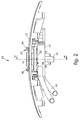
fig. 2 is a lateral view of the device infig. 1 ; -
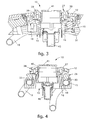
fig. 3 is a longitudinal section of the device infig. 2 ; -
fig. 4 is a section from IV to IV of the device infig. 2 ; -
fig. 5 is an exploded view of a knob, a pressure ring and a housing, used in the device infig. 2 ; -
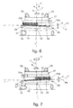
fig. 6 is a lateral view of the knob and the pressure ring infig. 5 , in a first operating condition; -
fig. 7 is a lateral view of the knob and the pressure ring infig. 5 , in a second operating condition. - With reference to
fig. 1 , adevice 10 according to the present invention can be used in a domestic electrical appliance, such as for example aniron 11 connected to aboiler 14, which is contained in a unit, or casing, separated from theiron 11 itself, in order to regulate the flow of steam from the latter. - The
device 10 comprises asupport 12, shown infig. 2 , having a shape that adapts to the aesthetics of the unit, and positioned on the front surface of the unit containing theboiler 14. - A housing 13 (
figs. 2 ,3 ,4 ,5 ,7 ) is made solid inside thesupport 12, and comprises two cylindrical walls, respectively outer 15 and inner 16, disposed concentric with each other and defining acentral seating 18, circular in shape, into which a segment oftube 19 is inserted, made of elastically deformable material, which connects theboiler 14 to theiron 11. Thecentral seating 18 is shaped in such a manner as to make the segment oftube 19 assume a U-shaped disposition. - The
housing 13 is also provided with two hollows, respectively first 21 and second 22 (fig. 5 ), made on theouter wall 15 on opposite sides, and with atooth 23, also made on theouter wall 15. The housing also comprises a pair of attachment elements, each of which is provided with twolittle hooks 24 which allow it to be attached to thesupport 12. - The
device 10 also comprises apressure ring 26 and a regulation knob 27 (figs. 3 to 7 ). - The
pressure ring 26 is inserted coaxially to theinner wall 16 in thecentral seating 18 and comprises two protrusions, respectively first 29 and second 30 which branch off radially, and atooth 31 that develops from a lower surface so as to contact the underlying segment oftube 19. - The two
protrusions respective hollows housing 13, so that the coupling of the protrusions-hollows prevents thepressure ring 26 from rotating with respect to thehousing 13. - On the outside, the
knob 27 has twogripper elements 39 and a throughhole 40 disposed centrally in which abutton 41 is inserted, free to slide with respect to the longitudinal axis X of theknob 27. - On one part of its lateral surface, the
knob 27 is provided with a toothed ring-nut 43 (fig. 5 ) able to cooperate with thetooth 23 of thehousing 13 in order to define a plurality of angular positions of theknob 27 with respect to thehousing 13. - The
knob 27 is disposed in such a manner that alower surface 35 thereof contacts anupper surface 36 of the pressure ring 26 (figs. 5 ,6 and 7 ). - The
lower surface 35 lies on a plane P (figs. 6 and 7 ) inclined with respect to a plane P1 orthogonal to the longitudinal axis X of theknob 27. The plane P is orthogonal to a longitudinal axis Y of thepressure ring 26, and has afirst portion 35a where the longitudinal thickness of theknob 27 is at its maximum and asecond portion 35b where the longitudinal thickness is at its minimum. The two planes P and P1, and hence the two longitudinal axes X and Y, are therefore inclined to each other by an angle β comprised between about 5° and about 15°. -
Fig. 6 shows a first operating condition of thedevice 10, in which theknob 27 is disposed in such a manner that thesecond portion 35b of thelower surface 35 is in correspondence with thetooth 31 of thepressure ring 26. In this first condition, thetooth 31 substantially does not exert any pressure on the segment oftube 19 below, thus allowing the flow of steam to pass. - As the
knob 27 rotates, thelower surface 35 of the latter rotates with respect to theupper surface 36 of thepressure ring 26 so that thefirst portion 35a approaches thetooth 31. The pressure exerted by the latter on the segment oftube 19 below increases, and therefore the cross section of thetube 19 decreases proportionally to the height assumed by thetooth 31 and hence the angular position of theknob 27. - Given that the first and
second portion lower surface 35, the useful field of rotation of theknob 27 is about 180°. - At the end of travel (
fig. 7 ), that is, when the rotation of theknob 27 has covered an angle of 180°, thefirst portion 35a of thelower surface 35 is in correspondence with thetooth 31, which is completely lowered on the segment oftube 19, reducing to a minimum the passage of steam in the segment oftube 19, and thus defining a second operating condition of thedevice 10. - The
device 10 according to the present invention therefore allows to effect a regulation of the flow of steam that can be graduated with great precision and in a wide range of values defined by the reciprocal position of the first andsecond portion lower surface 35 with respect to the position of thetooth 31 of thepressure ring 26 and the inclination β of the plane P with respect to the plane P1. - Moreover, the
tooth 23 and the toothed ring-nut 43 allow to temporarily and selectively clamp theknob 27 in a desired position of regulation, preventing unwanted variations in the angular position of theknob 27 itself. - According to the invention, the
inner wall 16 of thehousing 13 is tubular, so as to allow cooperation between thebutton 41, inserted in the throughhole 40, with aswitch 45 clamped to thehousing 13 and able to be used, for example, to enable or dis-enable the functioning of theboiler 14 of theiron 11. - It is clear that modifications and/or additions of parts may be made to the
device 10 as described heretofore, without departing from the scope of the present invention as defined by the appended claims. - According to a variant, instead of or together with the
button 41 and theswitch 45, another knob is used, able to rotate with respect to the longitudinal axis X, and cooperating with corresponding mechanical members attached to thehousing 13. - According to another variant, the
housing 13 defines a seating able to contain at least an indicator element, for example a manometer, integrated in the same structure with thepressure ring 26 and theknob 27, and able to indicate or display information connected to the state of functioning of theiron 11, for example the pressure of the steam in theboiler 14. - It is also clear that, although the present invention has been described with reference to some specific examples, a person of skill in the art shall certainly be able to achieve many other equivalent forms of device to regulate the flow of steam in a domestic electrical appliance, having the characteristics as set forth in the claims and hence all coming within the field of protection defined thereby.
Claims (12)
- Device to regulate the flow of steam in a domestic electrical appliance having steam generation means (14), elements (11) that use the steam generated by said generation means (14), and a pipe (19) made, at least for a segment, of elastically deformable material and able to convey said steam towards said elements (11), said device comprising at least a pressure element (26) connected to a drive element (27), free to rotate on a longitudinal axis (X), and able to exert a selectively variable pressure on said pipe (19) in order to regulate the quantity of said steam that flows through said pipe (19), characterized in that said drive element (27) comprises a thrust surface (35) lying on a first plane (P) inclined with respect to a second plane (P1) substantially orthogonal to said longitudinal axis (X), and in that said thrust surface (35) is disposed in contact with a mating surface (36) of said pressure element (26), in such a manner that the rotation of said drive element (27) determines a variation in the pressure exerted by said pressure element (26) on said pipe (19).
- Device as in claim 1, characterized in that said first and second planes (P, P1) define an angle (β) comprised between about 5° and about 15°.
- Device as in claim 1 or 2, characterized in that said pressure element (26) comprises contact means (31) cooperating with the outer surface of said segment of said pipe (19) and able to vary at least the cross section of said segment, so as to vary the pressure exerted on said segment.
- Device as in claim 3, characterized in that said contact means comprises at least a first tooth (31) protruding from a surface of said pressure element (26) opposite said mating surface (36).
- Device as in claim 4, characterized in that said contact means comprises at least two second teeth (33) disposed substantially equidistant from said first tooth (31) and defining a supporting fulcrum for the movement of said pressure element (26).
- Device as in any claim hereinbefore, characterized in that said pressure element (26) has a substantially annular shape.
- Device as in any claim hereinbefore, characterized in that said external drive element (27) has an at least partly cylindrical shape, hollow inside.
- Device as in any claim hereinbefore, characterized in that it further comprises housing means (13) able to house at least said segment of said pipe (19), said pressure element (26) and said external drive element (27).
- Device as in claim 8, characterized in that said housing means (13) defines a seating able to contain at least a command element (41, 45) integrated into the same structure with said pressure element (26) and said external drive element (27), and able to command, or regulate, at least said steam generation means (14).
- Device as in claim 9, characterized in that said command element comprises at least an actuation button (41) able to be axially actuated with respect to said longitudinal axis (X), and a switch (45) cooperating with said actuation button (41) and attached to said housing means (13).
- Device as in claim 8, characterized in that said housing means (13) defines a seating able to contain at least an indicator element integrated into the same structure with said pressure element (26) and said external drive element (27), and able to indicate or display information connected to the state of functioning of said domestic electrical appliance (11).
- Device as in claim 11, characterized in that said indicator element comprises at least a manometer able to display the value of pressure of the steam in said steam generation means (14).
Applications Claiming Priority (1)
| Application Number | Priority Date | Filing Date | Title |
|---|---|---|---|
| IT000114A ITUD20050114A1 (en) | 2005-07-05 | 2005-07-05 | DEVICE FOR ADJUSTING THE STEAM FLOW IN A APPLIANCE |
Publications (2)
| Publication Number | Publication Date |
|---|---|
| EP1741823A1 EP1741823A1 (en) | 2007-01-10 |
| EP1741823B1 true EP1741823B1 (en) | 2009-03-11 |
Family
ID=36274118
Family Applications (1)
| Application Number | Title | Priority Date | Filing Date |
|---|---|---|---|
| EP06116510A Expired - Lifetime EP1741823B1 (en) | 2005-07-05 | 2006-07-03 | Device to regulate the flow of steam in a domestic electrical appliance |
Country Status (4)
| Country | Link |
|---|---|
| EP (1) | EP1741823B1 (en) |
| AT (1) | ATE425295T1 (en) |
| DE (1) | DE602006005553D1 (en) |
| IT (1) | ITUD20050114A1 (en) |
Families Citing this family (2)
| Publication number | Priority date | Publication date | Assignee | Title |
|---|---|---|---|---|
| FR2916004B1 (en) * | 2007-05-07 | 2009-06-12 | Rowenta Werke Gmbh | APPARATUS FOR THE TREATMENT OF LAUNDRY COMPRISING A DEVICE FOR CONTROLLING THE FLOW OF WATER SENT TO A STEAM GENERATOR |
| WO2011076826A1 (en) * | 2009-12-22 | 2011-06-30 | BSH Bosch und Siemens Hausgeräte GmbH | Steam generator having an actuating element |
Family Cites Families (6)
| Publication number | Priority date | Publication date | Assignee | Title |
|---|---|---|---|---|
| FR1343057A (en) * | 1962-10-26 | 1965-11-26 | Further development of separate tank steam irons | |
| US4559667A (en) * | 1984-03-02 | 1985-12-24 | Regina Corporation | Dripless nozzle for a cleaning device |
| US4821996A (en) * | 1987-01-28 | 1989-04-18 | Baxter Travenol Laboratories, Inc. | Fluid flow control valve and transfer set |
| CH682801A5 (en) * | 1990-11-16 | 1993-11-30 | Radwulf Sa | Appliance appliances. |
| EP0849521B2 (en) * | 1996-12-18 | 2005-10-26 | De' Longhi S.p.A. | Device for controlling the flow of steam in domestic steam using electrical appliances |
| DE10106141B4 (en) * | 2001-02-10 | 2006-12-07 | INTER CONTROL Hermann Köhler Elektrik GmbH & Co KG | Thermally controlled device for actuating a valve opening, in particular a liquid valve |
-
2005
- 2005-07-05 IT IT000114A patent/ITUD20050114A1/en unknown
-
2006
- 2006-07-03 EP EP06116510A patent/EP1741823B1/en not_active Expired - Lifetime
- 2006-07-03 AT AT06116510T patent/ATE425295T1/en not_active IP Right Cessation
- 2006-07-03 DE DE602006005553T patent/DE602006005553D1/en not_active Expired - Fee Related
Also Published As
| Publication number | Publication date |
|---|---|
| ITUD20050114A1 (en) | 2007-01-06 |
| DE602006005553D1 (en) | 2009-04-23 |
| ATE425295T1 (en) | 2009-03-15 |
| EP1741823A1 (en) | 2007-01-10 |
Similar Documents
| Publication | Publication Date | Title |
|---|---|---|
| RU2674800C2 (en) | Fan assembly | |
| EP1419426B1 (en) | Pressure regulator | |
| JP6590623B2 (en) | Tube pump | |
| US6196475B1 (en) | Rotor nozzle | |
| CN108799565A (en) | Faucet and faucet user interface | |
| CN110159789A (en) | Valve | |
| EP1741823A1 (en) | Device to regulate the flow of steam in a domestic electrical appliance | |
| EP3418851A1 (en) | Controller | |
| US5180140A (en) | Hot/cold water mixing faucet and mounting structure therefor | |
| ES2645103T3 (en) | Feeder valve and push-button mechanism for multi-measure control of said feed valve | |
| US20080127999A1 (en) | Control user interface for laundry appliances | |
| CN105636730B (en) | Oblique angle stop device | |
| CA2874799A1 (en) | Support arm connection | |
| JP4973834B2 (en) | Pipette device | |
| EP0552591A2 (en) | Safety pressure sensor, in particular for microswitches | |
| EP0927426A1 (en) | Control knob used for household appliances | |
| WO1998011574A9 (en) | Control knob used for household appliances | |
| CN112004608B (en) | Spraying device | |
| JP4810667B2 (en) | Joystick controller | |
| US3476153A (en) | Foot control valve for dental machine | |
| CN205546116U (en) | Lighting console | |
| US2547630A (en) | Fluid-tight shield for rotatable shafts | |
| EP2156897A1 (en) | Multifunction shower head | |
| EP1421892B1 (en) | Regulation device to regulate the delivery of steam in a steam cleaning apparatus | |
| US12338900B2 (en) | Ceramic control valve |
Legal Events
| Date | Code | Title | Description |
|---|---|---|---|
| PUAI | Public reference made under article 153(3) epc to a published international application that has entered the european phase |
Free format text: ORIGINAL CODE: 0009012 |
|
| AK | Designated contracting states |
Kind code of ref document: A1 Designated state(s): AT BE BG CH CY CZ DE DK EE ES FI FR GB GR HU IE IS IT LI LT LU LV MC NL PL PT RO SE SI SK TR |
|
| AX | Request for extension of the european patent |
Extension state: AL BA HR MK YU |
|
| 17P | Request for examination filed |
Effective date: 20070706 |
|
| AKX | Designation fees paid |
Designated state(s): AT BE BG CH CY CZ DE DK EE ES FI FR GB GR HU IE IS IT LI LT LU LV MC NL PL PT RO SE SI SK TR |
|
| GRAP | Despatch of communication of intention to grant a patent |
Free format text: ORIGINAL CODE: EPIDOSNIGR1 |
|
| GRAS | Grant fee paid |
Free format text: ORIGINAL CODE: EPIDOSNIGR3 |
|
| GRAA | (expected) grant |
Free format text: ORIGINAL CODE: 0009210 |
|
| AK | Designated contracting states |
Kind code of ref document: B1 Designated state(s): AT BE BG CH CY CZ DE DK EE ES FI FR GB GR HU IE IS IT LI LT LU LV MC NL PL PT RO SE SI SK TR |
|
| REG | Reference to a national code |
Ref country code: GB Ref legal event code: FG4D |
|
| REG | Reference to a national code |
Ref country code: CH Ref legal event code: EP |
|
| REG | Reference to a national code |
Ref country code: IE Ref legal event code: FG4D |
|
| REF | Corresponds to: |
Ref document number: 602006005553 Country of ref document: DE Date of ref document: 20090423 Kind code of ref document: P |
|
| REG | Reference to a national code |
Ref country code: CH Ref legal event code: NV Representative=s name: R. A. EGLI & CO. PATENTANWAELTE |
|
| PG25 | Lapsed in a contracting state [announced via postgrant information from national office to epo] |
Ref country code: SI Free format text: LAPSE BECAUSE OF FAILURE TO SUBMIT A TRANSLATION OF THE DESCRIPTION OR TO PAY THE FEE WITHIN THE PRESCRIBED TIME-LIMIT Effective date: 20090311 Ref country code: FI Free format text: LAPSE BECAUSE OF FAILURE TO SUBMIT A TRANSLATION OF THE DESCRIPTION OR TO PAY THE FEE WITHIN THE PRESCRIBED TIME-LIMIT Effective date: 20090311 Ref country code: LT Free format text: LAPSE BECAUSE OF FAILURE TO SUBMIT A TRANSLATION OF THE DESCRIPTION OR TO PAY THE FEE WITHIN THE PRESCRIBED TIME-LIMIT Effective date: 20090311 |
|
| PG25 | Lapsed in a contracting state [announced via postgrant information from national office to epo] |
Ref country code: LV Free format text: LAPSE BECAUSE OF FAILURE TO SUBMIT A TRANSLATION OF THE DESCRIPTION OR TO PAY THE FEE WITHIN THE PRESCRIBED TIME-LIMIT Effective date: 20090311 Ref country code: SE Free format text: LAPSE BECAUSE OF FAILURE TO SUBMIT A TRANSLATION OF THE DESCRIPTION OR TO PAY THE FEE WITHIN THE PRESCRIBED TIME-LIMIT Effective date: 20090611 Ref country code: AT Free format text: LAPSE BECAUSE OF FAILURE TO SUBMIT A TRANSLATION OF THE DESCRIPTION OR TO PAY THE FEE WITHIN THE PRESCRIBED TIME-LIMIT Effective date: 20090311 Ref country code: PL Free format text: LAPSE BECAUSE OF FAILURE TO SUBMIT A TRANSLATION OF THE DESCRIPTION OR TO PAY THE FEE WITHIN THE PRESCRIBED TIME-LIMIT Effective date: 20090311 |
|
| PG25 | Lapsed in a contracting state [announced via postgrant information from national office to epo] |
Ref country code: BE Free format text: LAPSE BECAUSE OF FAILURE TO SUBMIT A TRANSLATION OF THE DESCRIPTION OR TO PAY THE FEE WITHIN THE PRESCRIBED TIME-LIMIT Effective date: 20090311 |
|
| PG25 | Lapsed in a contracting state [announced via postgrant information from national office to epo] |
Ref country code: EE Free format text: LAPSE BECAUSE OF FAILURE TO SUBMIT A TRANSLATION OF THE DESCRIPTION OR TO PAY THE FEE WITHIN THE PRESCRIBED TIME-LIMIT Effective date: 20090311 Ref country code: ES Free format text: LAPSE BECAUSE OF FAILURE TO SUBMIT A TRANSLATION OF THE DESCRIPTION OR TO PAY THE FEE WITHIN THE PRESCRIBED TIME-LIMIT Effective date: 20090622 Ref country code: PT Free format text: LAPSE BECAUSE OF FAILURE TO SUBMIT A TRANSLATION OF THE DESCRIPTION OR TO PAY THE FEE WITHIN THE PRESCRIBED TIME-LIMIT Effective date: 20090824 Ref country code: CZ Free format text: LAPSE BECAUSE OF FAILURE TO SUBMIT A TRANSLATION OF THE DESCRIPTION OR TO PAY THE FEE WITHIN THE PRESCRIBED TIME-LIMIT Effective date: 20090311 |
|
| PG25 | Lapsed in a contracting state [announced via postgrant information from national office to epo] |
Ref country code: RO Free format text: LAPSE BECAUSE OF FAILURE TO SUBMIT A TRANSLATION OF THE DESCRIPTION OR TO PAY THE FEE WITHIN THE PRESCRIBED TIME-LIMIT Effective date: 20090311 Ref country code: IS Free format text: LAPSE BECAUSE OF FAILURE TO SUBMIT A TRANSLATION OF THE DESCRIPTION OR TO PAY THE FEE WITHIN THE PRESCRIBED TIME-LIMIT Effective date: 20090711 Ref country code: SK Free format text: LAPSE BECAUSE OF FAILURE TO SUBMIT A TRANSLATION OF THE DESCRIPTION OR TO PAY THE FEE WITHIN THE PRESCRIBED TIME-LIMIT Effective date: 20090311 |
|
| PLBE | No opposition filed within time limit |
Free format text: ORIGINAL CODE: 0009261 |
|
| STAA | Information on the status of an ep patent application or granted ep patent |
Free format text: STATUS: NO OPPOSITION FILED WITHIN TIME LIMIT |
|
| PG25 | Lapsed in a contracting state [announced via postgrant information from national office to epo] |
Ref country code: DK Free format text: LAPSE BECAUSE OF FAILURE TO SUBMIT A TRANSLATION OF THE DESCRIPTION OR TO PAY THE FEE WITHIN THE PRESCRIBED TIME-LIMIT Effective date: 20090311 Ref country code: BG Free format text: LAPSE BECAUSE OF FAILURE TO SUBMIT A TRANSLATION OF THE DESCRIPTION OR TO PAY THE FEE WITHIN THE PRESCRIBED TIME-LIMIT Effective date: 20090611 |
|
| 26N | No opposition filed |
Effective date: 20091214 |
|
| PG25 | Lapsed in a contracting state [announced via postgrant information from national office to epo] |
Ref country code: MC Free format text: LAPSE BECAUSE OF NON-PAYMENT OF DUE FEES Effective date: 20090731 |
|
| REG | Reference to a national code |
Ref country code: FR Ref legal event code: ST Effective date: 20100331 |
|
| REG | Reference to a national code |
Ref country code: IE Ref legal event code: MM4A |
|
| PG25 | Lapsed in a contracting state [announced via postgrant information from national office to epo] |
Ref country code: FR Free format text: LAPSE BECAUSE OF NON-PAYMENT OF DUE FEES Effective date: 20090731 |
|
| PG25 | Lapsed in a contracting state [announced via postgrant information from national office to epo] |
Ref country code: DE Free format text: LAPSE BECAUSE OF NON-PAYMENT OF DUE FEES Effective date: 20100202 |
|
| PG25 | Lapsed in a contracting state [announced via postgrant information from national office to epo] |
Ref country code: IE Free format text: LAPSE BECAUSE OF NON-PAYMENT OF DUE FEES Effective date: 20090703 |
|
| PG25 | Lapsed in a contracting state [announced via postgrant information from national office to epo] |
Ref country code: GR Free format text: LAPSE BECAUSE OF FAILURE TO SUBMIT A TRANSLATION OF THE DESCRIPTION OR TO PAY THE FEE WITHIN THE PRESCRIBED TIME-LIMIT Effective date: 20090612 |
|
| GBPC | Gb: european patent ceased through non-payment of renewal fee |
Effective date: 20100703 |
|
| PG25 | Lapsed in a contracting state [announced via postgrant information from national office to epo] |
Ref country code: LU Free format text: LAPSE BECAUSE OF NON-PAYMENT OF DUE FEES Effective date: 20090703 |
|
| PG25 | Lapsed in a contracting state [announced via postgrant information from national office to epo] |
Ref country code: HU Free format text: LAPSE BECAUSE OF FAILURE TO SUBMIT A TRANSLATION OF THE DESCRIPTION OR TO PAY THE FEE WITHIN THE PRESCRIBED TIME-LIMIT Effective date: 20090912 |
|
| PG25 | Lapsed in a contracting state [announced via postgrant information from national office to epo] |
Ref country code: GB Free format text: LAPSE BECAUSE OF NON-PAYMENT OF DUE FEES Effective date: 20100703 |
|
| PG25 | Lapsed in a contracting state [announced via postgrant information from national office to epo] |
Ref country code: TR Free format text: LAPSE BECAUSE OF FAILURE TO SUBMIT A TRANSLATION OF THE DESCRIPTION OR TO PAY THE FEE WITHIN THE PRESCRIBED TIME-LIMIT Effective date: 20090311 |
|
| PG25 | Lapsed in a contracting state [announced via postgrant information from national office to epo] |
Ref country code: CY Free format text: LAPSE BECAUSE OF FAILURE TO SUBMIT A TRANSLATION OF THE DESCRIPTION OR TO PAY THE FEE WITHIN THE PRESCRIBED TIME-LIMIT Effective date: 20090311 |
|
| PGFP | Annual fee paid to national office [announced via postgrant information from national office to epo] |
Ref country code: NL Payment date: 20200710 Year of fee payment: 15 |
|
| PGFP | Annual fee paid to national office [announced via postgrant information from national office to epo] |
Ref country code: IT Payment date: 20200715 Year of fee payment: 15 Ref country code: CH Payment date: 20200713 Year of fee payment: 15 |
|
| REG | Reference to a national code |
Ref country code: CH Ref legal event code: PL |
|
| REG | Reference to a national code |
Ref country code: NL Ref legal event code: MM Effective date: 20210801 |
|
| PG25 | Lapsed in a contracting state [announced via postgrant information from national office to epo] |
Ref country code: LI Free format text: LAPSE BECAUSE OF NON-PAYMENT OF DUE FEES Effective date: 20210731 Ref country code: CH Free format text: LAPSE BECAUSE OF NON-PAYMENT OF DUE FEES Effective date: 20210731 |
|
| PG25 | Lapsed in a contracting state [announced via postgrant information from national office to epo] |
Ref country code: NL Free format text: LAPSE BECAUSE OF NON-PAYMENT OF DUE FEES Effective date: 20210801 |
|
| PG25 | Lapsed in a contracting state [announced via postgrant information from national office to epo] |
Ref country code: IT Free format text: LAPSE BECAUSE OF NON-PAYMENT OF DUE FEES Effective date: 20210703 |