EP1740906B1 - Dark-banded vial for use with level - Google Patents
Dark-banded vial for use with level Download PDFInfo
- Publication number
- EP1740906B1 EP1740906B1 EP05736217A EP05736217A EP1740906B1 EP 1740906 B1 EP1740906 B1 EP 1740906B1 EP 05736217 A EP05736217 A EP 05736217A EP 05736217 A EP05736217 A EP 05736217A EP 1740906 B1 EP1740906 B1 EP 1740906B1
- Authority
- EP
- European Patent Office
- Prior art keywords
- vial
- bands
- bubble
- cavity
- dark
- Prior art date
- Legal status (The legal status is an assumption and is not a legal conclusion. Google has not performed a legal analysis and makes no representation as to the accuracy of the status listed.)
- Expired - Lifetime
Links
Images
Classifications
-
- G—PHYSICS
- G01—MEASURING; TESTING
- G01C—MEASURING DISTANCES, LEVELS OR BEARINGS; SURVEYING; NAVIGATION; GYROSCOPIC INSTRUMENTS; PHOTOGRAMMETRY OR VIDEOGRAMMETRY
- G01C9/00—Measuring inclination, e.g. by clinometers, by levels
- G01C9/18—Measuring inclination, e.g. by clinometers, by levels by using liquids
- G01C9/24—Measuring inclination, e.g. by clinometers, by levels by using liquids in closed containers partially filled with liquid so as to leave a gas bubble
- G01C9/34—Measuring inclination, e.g. by clinometers, by levels by using liquids in closed containers partially filled with liquid so as to leave a gas bubble of the tubular type, i.e. for indicating the level in one direction only
-
- G—PHYSICS
- G01—MEASURING; TESTING
- G01C—MEASURING DISTANCES, LEVELS OR BEARINGS; SURVEYING; NAVIGATION; GYROSCOPIC INSTRUMENTS; PHOTOGRAMMETRY OR VIDEOGRAMMETRY
- G01C9/00—Measuring inclination, e.g. by clinometers, by levels
- G01C9/18—Measuring inclination, e.g. by clinometers, by levels by using liquids
- G01C9/24—Measuring inclination, e.g. by clinometers, by levels by using liquids in closed containers partially filled with liquid so as to leave a gas bubble
- G01C9/26—Details
- G01C9/32—Means for facilitating the observation of the position of the bubble, e.g. illuminating means
Definitions
- This invention is related generally to vials and, more particularly, to vials enclosing a bubble for use in levels.
- Spirit levels also called bubble levels
- bubble levels are well known instruments utilizing gravity in this way to set horizontal or vertical surfaces.
- levels include a sealed vial containing a bubble, typically air, floating in a non-freezing liquid, usually mineral spirits. The measured surface is considered horizontal or vertical when the air bubble rests between predetermined graduated marks on the vial.
- the accuracy with which a horizontal or vertical plane can be determined is critically dependent on the accuracy at which the bubble is centered between the transverse marks on the vial which, of course, is dependent on the visibility of such lines and the outline of the bubble itself. While the position of the bubble can readily be seen under normal lighting conditions, it becomes difficult to see on a heavily clouded day, or at dusk, or in poorly lighted spaces. That is to say, typical conventional levels can be effectively used only in relatively well-lighted environments and, accordingly can put constraints on the times and places craftsmen such as carpenters and bricklayers are able to work efficiently.
- Document US-A-5 414 937 shows a spirit level with an elongate bubble vial surrounded by a black strip and a black cap.
- the darkened surfaces are reflected and refracted at the interface between the bubble and the liquid.
- the contour of the bubble is emphasized by a dark ring.
- bubble illumination devices may work well in dark conditions, but they provide little assistance when operating in dimly lit or more well lit areas in which the bubble may blend in with the background when viewing the vial.
- Floats may increase visibility, but their inclusion in the vial often results in less precise measurements.
- Levels including electrical and fiber optic sensing means are typically too expensive and too sensitive to be handled easily at work sites and may not provide any enhancement to viewing the bubble in certain conditions.
- Another object of the invention is to provide a level utilizing a vial providing increased visibility of the bubble therein.
- Another object of the invention is to provide a method of measuring the levelness of an element including utilizing a vial providing increased visibility of the bubble therein.
- Another object of the invention is to provide a vial having bands circumscribing the vial's cavity and positioned on opposite sides of the cavity's maximum diameter to enhance visibility of the bubble therein.
- Another object of the invention is to provide a vial and level having enhanced bubble visibility which do not require special handling at work sites and which do not require significant additional costs of manufacturing.
- Another object of the invention is to provide a vial and level providing for enhanced bubble visibility in conditions when the interface between the bubble and liquid in the vial is otherwise difficult to discern.
- Still another object of the invention is to provide a level which operates well in a variety of lighting conditions and which provides for easy location of the bubble within the vial.
- the invention is a vial for use in a level which provides for enhanced readability.
- the invention represents a significant advance over the state of the art by providing novel elements, including a pair of bands to increase the visibility of the bubble within the vial.
- the vial comprises a body having first and second ends, a midpoint, interior and exterior surfaces, at least one marker ring connected with respect to the body, a cavity, a bubble positioned in the cavity and defined by an interface, and first and second dark-colored bands circumscribing the cavity with the first band positioned between the first end and the midpoint and the second band positioned between the second end and the midpoint.
- the interface preferably a gas-liquid interface, reflects the first and second bands to cause the interface to appear dark-colored when viewing the bubble from outside the exterior surface, thereby enhancing visibility of the bubble.
- dark or “dark-colored” refer to black and those colors approaching black in hue including, for example, dark grey, dark blue, dark green, dark brown, and the like.
- the cavity is preferably barrel-shaped, i.e., cross-sections of the cavity increase in diameter, reach a maximum diameter, then decrease in diameter.
- the maximum diameter is preferably near the midpoint which may or may not be equidistant to the first and second ends.
- the body is preferably cylindrical.
- the bands may be opaque such that light does not pass through them or they may be translucent or tinted such that some light passes through.
- the bands may be positioned on the exterior surface of the body, on the interior surface of the body, or between the interior and exterior surfaces of the body. Alternatively, the bands may be integral with the body and, in such cases, may be comprised of opaque or translucent portions of the body. In certain embodiments, the bands are wider than the bubble.
- the vial may further include first and second end closures.
- the end closures are integral with the body and include portions of the interior surface which defines the cavity.
- such end closures may be dark-colored and may provide further reflection to the interface in addition to that of the bands.
- the at least one marker ring is preferably visible from outside the exterior surface of the vial.
- the vial preferably includes first and second marker rings which are equidistant to the maximum diameter to allow a user to determine when a bubble is positioned at the maximum diameter.
- the first ring is preferably positioned between the maximum diameter and the first end and the second ring is preferably positioned between the maximum diameter and the second end.
- Such rings may be positioned on the exterior surface or on the interior surface, though it is preferred that the rings be positioned between the interior and exterior surfaces.
- the invention may also be described as a level for improved measurement.
- a level comprises a measuring surface for contacting an element to be measured, a recess formed in the level at an angular relationship to the measuring surface, and a vial received in the recess.
- the vial preferably comprises a body having first and second ends, a midpoint, and interior and exterior surfaces, at least one marker ring connected with respect to the body, the at least one marker ring visible from outside the exterior surface, a bubble positioned in the cavity and defined by an interface, and first and second dark-colored bands circumscribing the cavity with the first band positioned between the first end and the midpoint and the second band positioned between the second end and the midpoint.
- the interface is preferably a gas-liquid interface, though it is believed that it may be the interface between two immiscible fluids.
- the interior surface defines a cavity which preferably has a maximum diameter near the midpoint.
- the bubble rests at the maximum diameter when the vial is oriented perpendicular to the force of gravity.
- the vial includes first and second marker rings equidistant to the maximum diameter, the first ring positioned between the maximum diameter and the first end and the second ring positioned between the maximum diameter and the second end.
- Such rings may be positioned on the interior surface or exterior surface though it is most preferable that they be positioned between the interior and exterior surfaces.
- the maximum diameter is positioned at the midpoint, the first and second marker rings are positioned equidistant to the maximum diameter, and the bands are positioned equidistant to the maximum diameter.
- the reflection of the bands on the interface of the bubble is even, i.e., because the vial is symmetrical, the reflection of the first band on the interface is the same as the reflection of the second band on the interface when viewing the bubble from a position in the plane perpendicular to the vial and including the maximum diameter.
- the bands may be opaque such that light does not pass through them or they may be translucent or tinted such that some light passes through.
- the bands may be positioned on the exterior surface of the body, on the interior surface of the body, or between the interior and exterior surfaces of the body.
- the bands may be integral with the body and, in such cases, may be comprised of opaque or translucent portions of the body.
- the invention also includes a method of measuring the levelness of an element.
- the method comprises providing a level having a measuring surface and a vial positioned at a predetermined angular relationship thereto, positioning the measuring surface on the element, and assessing the levelness of the element by locating the position of the bubble.
- Such a method is facilitated by using a vial comprising a body having first and second ends, a midpoint, and interior and exterior surfaces, the interior surface defining a cavity; at least one marker ring connected with respect to the body, the at least one marker ring visible from outside the exterior surface; a bubble positioned in the cavity, the bubble defined by a gas-liquid interface; and first and second dark-colored bands circumscribing the cavity, the first band positioned between the first end and the midpoint and the second band positioned between the second end and the midpoint.
- the bands facilitate locating the bubble by reflecting off of the interface to increase visibility of the bubble.
- Such a method may be further enhanced by using bands which are symmetrical about the maximum diameter of the cavity.
- bands may be opaque such that light does not pass through them or they may be translucent or tinted such that some light passes through.
- the bands may be positioned on the exterior surface of the body, on the interior surface of the body, or between the interior and exterior surfaces of the body. Alternatively, the bands may be integral with the body and, in such cases, may be comprised of opaque or translucent portions of the body.
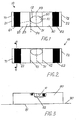
- FIGURE 1 is a top plan view and FIGURE 2 is a front elevation of an embodiment of a vial 10.
- Vial 10 includes a body 20 having a first end 21 and second end 22 with a midpoint 23 therebetween.
- Vial 10 is preferably made of a plastic material such as acrylic, polycarbonate, polystyrene, butyrates or the like, and is transparent.
- An interior surface 24 of body 20 defines a barrel-shaped cavity 30 such that there exists a cross-section of the cavity 30 which has a maximum diameter 31.
- Maximum diameter 31 is preferably positioned near or at midpoint 23.
- Vial 10 further includes a pair of marker rings 41 and 42 connected with respect to body 20. Marker rings 41 and 42 are preferably equidistant to maximum diameter 31. As shown, a bubble 50 is positioned within cavity 30 at maximum diameter 31 and between marker rings 41 and 42. Bubble 50 is defined by a gas-liquid interface 51 with bubble 50 being a gas 52 and the rest of cavity 30 being filled with a liquid 53. Gas 52 is preferably air and liquid 53 is preferably mineral spirits or the like.
- Vial 10 also includes dark-colored bands 61 and 62 circumscribing cavity 30.
- First band 61 is positioned between maximum diameter 31 and first end 21 and second band 62 is positioned between maximum diameter 31 and second end 22.
- Vial 10 further includes end closures 71 and 72 at first end 21 and second end 22.
- First end closure 71 is at first end 21 and second end closure 72 is at second end 22.
- First and second end closures 71 and 72 are preferably integral with body 20 and enclose cavity 30.
- FIGURE 1 shows bubble 50 positioned at maximum diameter 31.
- Viewing line 54 shows how first band 61 is reflected off of interface 51 when viewing vial 10 from the side.
- innumerable reflections of bands 61 and 62 off of interface 51 provide the viewer with a dark-colored outline of bubble 50 along its perimeter.
- Interface 51 between the viewer and bubble 50 i.e., the central portion of bubble 50 in FIGURE 1 , appears to not reflect the bands.
- bands 61 and 62 are about 1 ⁇ 2 inch wide and are equidistant to bubble 50 when positioned at maximum diameter 31.
- Each of bands 61 and 62 may be about 1 ⁇ 2 inch from maximum diameter 31.
- FIGURE 3 is a front elevation of a level 80 including vial 10.
- Level 80 includes a measuring surface 81 for contacting an element such as a building surface 90 to be measured.
- a recess 82 is formed in level 80 at an angular relationship to measuring surface 81.
- Recess 82 receives and holds vial 10 at an angular relationship to measuring surface 81.
- vial 10 is parallel to measuring surface 81.
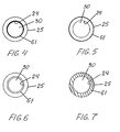
- FIGURE 5 shows a cross-section view of vial 10 taken along line 4-4 of FIGURE 2 in which first band 61 has been applied to an exterior surface 25 of vial 10.
- FIGURES 4, 6, and 7 are alternate cross-section views of vial 10 taken along line 4-4 of FIGURE 2 .
- first band 61 is shown on interior surface 24 of vial 10.
- first band 61 is shown in body 20 between interior surface 24 and exterior surface 25.
- Such an embodiment may include a dual component overmolded vial 10 in which bands 61 and 62 are positioned on an inner cylinder before an outer sleeve is molding around the cylinder and sleeve.
- bands 61 and 62 may be a foil comprised of metal, thermoset material, thermoplastic material having a high melting point, ink, pigment or other dark material, and bands 61 and 62 may be hot stamped, pressed or rolled into, printed onto or otherwise applied to body 20.
- first band 61 is integral with body 20 and can be said to be positioned between interior surface 24 and exterior surfaces 25 of body 20.
- bands 61 and 62 may be comprised of opaque or translucent portions of the body.
Landscapes
- Physics & Mathematics (AREA)
- Engineering & Computer Science (AREA)
- General Physics & Mathematics (AREA)
- Radar, Positioning & Navigation (AREA)
- Remote Sensing (AREA)
- Medical Preparation Storing Or Oral Administration Devices (AREA)
- Details Of Rigid Or Semi-Rigid Containers (AREA)
- Measurement Of Levels Of Liquids Or Fluent Solid Materials (AREA)
- Medicines Containing Material From Animals Or Micro-Organisms (AREA)
- Compositions Of Macromolecular Compounds (AREA)
Abstract
Description
- This invention is related generally to vials and, more particularly, to vials enclosing a bubble for use in levels.
- It has long been known to utilize the effect of gravity on fluids having different densities to determine the levelness of elements such as building components, machines, lines, poles, etc. Spirit levels, also called bubble levels, are well known instruments utilizing gravity in this way to set horizontal or vertical surfaces. Such levels include a sealed vial containing a bubble, typically air, floating in a non-freezing liquid, usually mineral spirits. The measured surface is considered horizontal or vertical when the air bubble rests between predetermined graduated marks on the vial.
- The accuracy with which a horizontal or vertical plane can be determined is critically dependent on the accuracy at which the bubble is centered between the transverse marks on the vial which, of course, is dependent on the visibility of such lines and the outline of the bubble itself. While the position of the bubble can readily be seen under normal lighting conditions, it becomes difficult to see on a heavily clouded day, or at dusk, or in poorly lighted spaces. That is to say, typical conventional levels can be effectively used only in relatively well-lighted environments and, accordingly can put constraints on the times and places craftsmen such as carpenters and bricklayers are able to work efficiently.
- Because it is frequently necessary to measure or set the levelness of a horizontal surface or to set or plumb a vertical surface in less than ideal conditions for locating the position of the bubble in the vial there have been many attempts to provide a level having a more easily located bubble. For instance, others have provided an illumination device in the level to illuminate the vial to enhance visibility of the bubble. Another attempt to enhance bubble visibility included the use of a floating object within the vial. Still other attempts have utilized complicated electrical or fiber optic sensing of the bubble position.
- Document
US-A-5 414 937 shows a spirit level with an elongate bubble vial surrounded by a black strip and a black cap. When viewing the vial from above, the darkened surfaces are reflected and refracted at the interface between the bubble and the liquid. Thus, the contour of the bubble is emphasized by a dark ring. - Each of these prior art attempts have failed to provide a simple and inexpensive, yet successful method of overcoming bubble-locating problems. For example, bubble illumination devices may work well in dark conditions, but they provide little assistance when operating in dimly lit or more well lit areas in which the bubble may blend in with the background when viewing the vial. Floats may increase visibility, but their inclusion in the vial often results in less precise measurements. Levels including electrical and fiber optic sensing means are typically too expensive and too sensitive to be handled easily at work sites and may not provide any enhancement to viewing the bubble in certain conditions.
- Therefore, there is a need for an improved vial and level which provide increased visibility of the bubble to aid in the location of the bubble during measurements. Furthermore, there is a need for such an improved vial and level which do not require special handling at work sites and which do not require significant additional costs of manufacturing. In addition, there is a need to provide a vial and level which operate well in a variety of lighting conditions and which provide for easy location of the bubble within the vial.
- It is an object of the invention to provide an improved vial for use in levels which enhances visibility of the bubble therein.
- Another object of the invention is to provide a level utilizing a vial providing increased visibility of the bubble therein.
- Another object of the invention is to provide a method of measuring the levelness of an element including utilizing a vial providing increased visibility of the bubble therein.
- Another object of the invention is to provide a vial having bands circumscribing the vial's cavity and positioned on opposite sides of the cavity's maximum diameter to enhance visibility of the bubble therein.
- Another object of the invention is to provide a vial and level having enhanced bubble visibility which do not require special handling at work sites and which do not require significant additional costs of manufacturing.
- Another object of the invention is to provide a vial and level providing for enhanced bubble visibility in conditions when the interface between the bubble and liquid in the vial is otherwise difficult to discern.
- Still another object of the invention is to provide a level which operates well in a variety of lighting conditions and which provides for easy location of the bubble within the vial.
- These and other objects of the invention will be apparent from the following descriptions and from the drawings.
- In at least one embodiment, the invention is a vial for use in a level which provides for enhanced readability. The invention represents a significant advance over the state of the art by providing novel elements, including a pair of bands to increase the visibility of the bubble within the vial.
- In one embodiment the vial comprises a body having first and second ends, a midpoint, interior and exterior surfaces, at least one marker ring connected with respect to the body, a cavity, a bubble positioned in the cavity and defined by an interface, and first and second dark-colored bands circumscribing the cavity with the first band positioned between the first end and the midpoint and the second band positioned between the second end and the midpoint. In such a vial, the interface, preferably a gas-liquid interface, reflects the first and second bands to cause the interface to appear dark-colored when viewing the bubble from outside the exterior surface, thereby enhancing visibility of the bubble. As used herein, "dark" or "dark-colored" refer to black and those colors approaching black in hue including, for example, dark grey, dark blue, dark green, dark brown, and the like.
- In such an embodiment, the cavity is preferably barrel-shaped, i.e., cross-sections of the cavity increase in diameter, reach a maximum diameter, then decrease in diameter. The maximum diameter is preferably near the midpoint which may or may not be equidistant to the first and second ends. The body is preferably cylindrical.
- The bands may be opaque such that light does not pass through them or they may be translucent or tinted such that some light passes through. The bands may be positioned on the exterior surface of the body, on the interior surface of the body, or between the interior and exterior surfaces of the body. Alternatively, the bands may be integral with the body and, in such cases, may be comprised of opaque or translucent portions of the body. In certain embodiments, the bands are wider than the bubble.
- The vial may further include first and second end closures. In preferred embodiments, the end closures are integral with the body and include portions of the interior surface which defines the cavity. In certain embodiments, such end closures may be dark-colored and may provide further reflection to the interface in addition to that of the bands.
- The at least one marker ring is preferably visible from outside the exterior surface of the vial. The vial preferably includes first and second marker rings which are equidistant to the maximum diameter to allow a user to determine when a bubble is positioned at the maximum diameter. The first ring is preferably positioned between the maximum diameter and the first end and the second ring is preferably positioned between the maximum diameter and the second end. Such rings may be positioned on the exterior surface or on the interior surface, though it is preferred that the rings be positioned between the interior and exterior surfaces.
- The invention may also be described as a level for improved measurement. Such a level comprises a measuring surface for contacting an element to be measured, a recess formed in the level at an angular relationship to the measuring surface, and a vial received in the recess. The vial preferably comprises a body having first and second ends, a midpoint, and interior and exterior surfaces, at least one marker ring connected with respect to the body, the at least one marker ring visible from outside the exterior surface, a bubble positioned in the cavity and defined by an interface, and first and second dark-colored bands circumscribing the cavity with the first band positioned between the first end and the midpoint and the second band positioned between the second end and the midpoint. Measurement of the element is facilitated by reflection of the first and second bands on the interface such that the interface appears dark-colored when viewing the bubble. The interface is preferably a gas-liquid interface, though it is believed that it may be the interface between two immiscible fluids.
- The interior surface defines a cavity which preferably has a maximum diameter near the midpoint. The bubble rests at the maximum diameter when the vial is oriented perpendicular to the force of gravity. In certain embodiments, the vial includes first and second marker rings equidistant to the maximum diameter, the first ring positioned between the maximum diameter and the first end and the second ring positioned between the maximum diameter and the second end. Such rings may be positioned on the interior surface or exterior surface though it is most preferable that they be positioned between the interior and exterior surfaces.
- In a highly preferred embodiment, the maximum diameter is positioned at the midpoint, the first and second marker rings are positioned equidistant to the maximum diameter, and the bands are positioned equidistant to the maximum diameter. In such an embodiment, the reflection of the bands on the interface of the bubble is even, i.e., because the vial is symmetrical, the reflection of the first band on the interface is the same as the reflection of the second band on the interface when viewing the bubble from a position in the plane perpendicular to the vial and including the maximum diameter.
- As stated above in reference to another embodiment of the invention, the bands may be opaque such that light does not pass through them or they may be translucent or tinted such that some light passes through. The bands may be positioned on the exterior surface of the body, on the interior surface of the body, or between the interior and exterior surfaces of the body. Alternatively, the bands may be integral with the body and, in such cases, may be comprised of opaque or translucent portions of the body.
- The invention also includes a method of measuring the levelness of an element. The method comprises providing a level having a measuring surface and a vial positioned at a predetermined angular relationship thereto, positioning the measuring surface on the element, and assessing the levelness of the element by locating the position of the bubble.
- Such a method is facilitated by using a vial comprising a body having first and second ends, a midpoint, and interior and exterior surfaces, the interior surface defining a cavity; at least one marker ring connected with respect to the body, the at least one marker ring visible from outside the exterior surface; a bubble positioned in the cavity, the bubble defined by a gas-liquid interface; and first and second dark-colored bands circumscribing the cavity, the first band positioned between the first end and the midpoint and the second band positioned between the second end and the midpoint.
- When using such a vial in the above method, the bands facilitate locating the bubble by reflecting off of the interface to increase visibility of the bubble. Such a method may be further enhanced by using bands which are symmetrical about the maximum diameter of the cavity. As discussed above, such bands may be opaque such that light does not pass through them or they may be translucent or tinted such that some light passes through. The bands may be positioned on the exterior surface of the body, on the interior surface of the body, or between the interior and exterior surfaces of the body. Alternatively, the bands may be integral with the body and, in such cases, may be comprised of opaque or translucent portions of the body.
-
-
FIGURE 1 is a top plan view of a vial in accordance with this invention. -
FIGURE 2 is a front elevation of the vial ofFIGURE 1 . -
FIGURE 3 is a front elevation of a level including the vial ofFIGURES 1 and 2 and having two broken-away portions to better illustrate aspects of the invention. -
FIGURE 4 is a cross-section view of the vial taken along section 4-4 as shown inFIGURE 2 . -
FIGURE 5 is a cross-section view similar toFIGURE 4 but showing a vial which is an alternate embodiment of the invention. -
FIGURE 6 is another cross-section view illustrating another vial which is yet another embodiment of the invention. -
FIGURE 7 is a cross-section view of yet another vial showing another embodiment of the invention. -
FIGURE 1 is a top plan view andFIGURE 2 is a front elevation of an embodiment of avial 10.Vial 10 includes abody 20 having afirst end 21 andsecond end 22 with amidpoint 23 therebetween.Vial 10 is preferably made of a plastic material such as acrylic, polycarbonate, polystyrene, butyrates or the like, and is transparent. Aninterior surface 24 ofbody 20 defines a barrel-shapedcavity 30 such that there exists a cross-section of thecavity 30 which has amaximum diameter 31.Maximum diameter 31 is preferably positioned near or atmidpoint 23. -
Vial 10 further includes a pair of marker rings 41 and 42 connected with respect tobody 20. Marker rings 41 and 42 are preferably equidistant tomaximum diameter 31. As shown, abubble 50 is positioned withincavity 30 atmaximum diameter 31 and between marker rings 41 and 42.Bubble 50 is defined by a gas-liquid interface 51 withbubble 50 being agas 52 and the rest ofcavity 30 being filled with a liquid 53.Gas 52 is preferably air and liquid 53 is preferably mineral spirits or the like. -
Vial 10 also includes dark-colored bands cavity 30.First band 61 is positioned betweenmaximum diameter 31 andfirst end 21 andsecond band 62 is positioned betweenmaximum diameter 31 andsecond end 22. -
Vial 10 further includesend closures first end 21 andsecond end 22.First end closure 71 is atfirst end 21 andsecond end closure 72 is atsecond end 22. First andsecond end closures body 20 and enclosecavity 30. -
FIGURE 1 showsbubble 50 positioned atmaximum diameter 31. Viewingline 54 shows howfirst band 61 is reflected off ofinterface 51 when viewingvial 10 from the side. As is apparent, innumerable reflections ofbands interface 51 provide the viewer with a dark-colored outline ofbubble 50 along its perimeter.Interface 51 between the viewer andbubble 50, i.e., the central portion ofbubble 50 inFIGURE 1 , appears to not reflect the bands. In a preferred embodiment,bands bubble 50 when positioned atmaximum diameter 31. Each ofbands maximum diameter 31. -
FIGURE 3 is a front elevation of alevel 80 includingvial 10.Level 80 includes a measuringsurface 81 for contacting an element such as abuilding surface 90 to be measured. Arecess 82 is formed inlevel 80 at an angular relationship to measuringsurface 81.Recess 82 receives and holdsvial 10 at an angular relationship to measuringsurface 81. As shown,vial 10 is parallel to measuringsurface 81. -
FIGURE 5 shows a cross-section view ofvial 10 taken along line 4-4 ofFIGURE 2 in whichfirst band 61 has been applied to anexterior surface 25 ofvial 10.FIGURES 4, 6, and 7 are alternate cross-section views ofvial 10 taken along line 4-4 ofFIGURE 2 . InFIGURE 4 ,first band 61 is shown oninterior surface 24 ofvial 10. InFIGURE 6 ,first band 61 is shown inbody 20 betweeninterior surface 24 andexterior surface 25. Such an embodiment may include a dual componentovermolded vial 10 in whichbands FIGURES 4-6 ,bands bands body 20. InFIGURE 7 ,first band 61 is integral withbody 20 and can be said to be positioned betweeninterior surface 24 andexterior surfaces 25 ofbody 20. In such embodiment,bands - Thus, it should be apparent that there has been provided, in accordance with the present invention, a vial for use with levels that fully satisfies the objectives and advantages set forth above.
- Although the invention has been described in conjunction with specific embodiments thereof, it is evident that many alternatives, modifications and variations will be apparent to those skilled in the art. Accordingly, it is intended to embrace all such alternatives, modifications and variations that fall within the scope of the appended claims.
Claims (13)
- A vial (10) for use in a level, the vial comprising:• a body (20) having first and second ends (21,22), a midpoint (23), and interior and exterior surfaces, the interior surface (24) defining a barrel-shaped cavity (30), the cavity having a maximum diameter (31) near the midpoint;• first and second marker rings (41,42) connected with respect to the body-on either side of the midpoint and visible from the outside of the vial;• a liquid (53) and gas bubble (50) in the cavity, the bubble defined by the liquid-gas interface (51); and• first and second dark bands (61,62) circumscribing the cavity, the first band positioned between the first end and the first marker ring and the second band positioned between the second end and the second marker ring;whereby the interface reflects the first and second dark bands such that the interface appears dark when viewing the bubble to enhance visibility of the bubble.
- The vial of claim 1 wherein the bands are opaque.
- The vial of claim 1 wherein the bands are on the exterior surface of the body.
- The vial of claim 1 wherein the bands are on the interior surface of the body.
- The vial of claim 1 wherein the bands are between the interior and exterior surfaces of the body.
- The vial of claim 1 wherein the bands are integral with the body.
- The vial of claim 1 wherein the body includes first and second end closures.
- A level (80) for improved measurement, the level comprising:• a measuring surface (81) for contacting an element (90) to be measured;• a recess (82) formed in the level at an angular relationship to the measuring surface; and• a vial (10) received in the recess, the vial comprising:whereby measuring the element is facilitated by reflection of the first and second dark bands on the interface such that the interface appears dark when viewing the bubble.- a body (20) having first and second ends (21,22), a midpoint (23), and interior and exterior surfaces, the interior surface (24) defining a cavity, the cavity (30) having a maximum diameter (31) near the midpoint;- first and second marker rings (41,42) connected with respect to the body on either side of the midpoint and visible from the outside of the vial;- a liquid (53) and gas bubble (50) in the cavity, the bubble defined by the liquid-gas interface (51); and- first and second dark bands (61,62) circumscribing the cavity, the first band positioned between the first end and the first marker ring and the second band positioned between the second end and the second marker ring;
- The level of claim 8 wherein the bands are opaque.
- The vial of claim 8 wherein the bands are on one of the surfaces of the body.
- The vial of claim 8 wherein the bands are between the interior and exterior surfaces of the body.
- The vial of claim 8 wherein the bands are integral with the body.
- The vial of claim 8 wherein the vial includes first and second marker rings equidistant to the maximum diameter, the first ring positioned between the maximum diameter and the first end and the second ring positioned between the maximum diameter and the second end.
Applications Claiming Priority (2)
| Application Number | Priority Date | Filing Date | Title |
|---|---|---|---|
| US10/826,854 US6957494B1 (en) | 2004-04-16 | 2004-04-16 | Dark-banded vial for use with level |
| PCT/US2005/013061 WO2005103614A2 (en) | 2004-04-16 | 2005-04-18 | Dark-banded vial for use with level |
Publications (3)
| Publication Number | Publication Date |
|---|---|
| EP1740906A2 EP1740906A2 (en) | 2007-01-10 |
| EP1740906A4 EP1740906A4 (en) | 2007-12-19 |
| EP1740906B1 true EP1740906B1 (en) | 2011-06-08 |
Family
ID=35094742
Family Applications (1)
| Application Number | Title | Priority Date | Filing Date |
|---|---|---|---|
| EP05736217A Expired - Lifetime EP1740906B1 (en) | 2004-04-16 | 2005-04-18 | Dark-banded vial for use with level |
Country Status (12)
| Country | Link |
|---|---|
| US (1) | US6957494B1 (en) |
| EP (1) | EP1740906B1 (en) |
| JP (1) | JP5089379B2 (en) |
| CN (1) | CN1942737B (en) |
| AT (1) | ATE512349T1 (en) |
| AU (1) | AU2005236455B2 (en) |
| CA (1) | CA2563633C (en) |
| IL (1) | IL178534A0 (en) |
| MX (1) | MXPA06011660A (en) |
| NZ (1) | NZ550194A (en) |
| TW (1) | TWI369480B (en) |
| WO (1) | WO2005103614A2 (en) |
Families Citing this family (21)
| Publication number | Priority date | Publication date | Assignee | Title |
|---|---|---|---|---|
| US6673283B2 (en) * | 2002-01-30 | 2004-01-06 | Empire Level Mfg. Corp. | Method for optical control of an adjustable core pin for vial molding |
| DE202004006643U1 (en) * | 2004-03-12 | 2005-07-21 | Stabila-Meßgeräte Gustav Ullrich GmbH | Spirit level with an injection molded body that incorporates thermoplastic strengthening inserts which are at least partially enclosed by the injection molding process |
| US7086167B2 (en) * | 2004-04-16 | 2006-08-08 | Empire Level Mfg. Corp. | Overmolded vial for use with a level |
| DE202007000049U1 (en) * | 2007-11-29 | 2009-04-09 | Stabila-Meßgeräte Gustav Ullrich GmbH | spirit level |
| IL195885A0 (en) * | 2008-12-11 | 2009-09-01 | Kapro Ind Ltd | Spirit level with color contrasted bubble vial |
| US8359757B1 (en) * | 2009-07-15 | 2013-01-29 | Ruys Robert C | Illuminating carpenter's level |
| US8336221B2 (en) * | 2009-10-27 | 2012-12-25 | Milwaukee Electric Tool Corporation | Level |
| WO2011070561A1 (en) | 2009-12-13 | 2011-06-16 | Kapro Industries Ltd | Bubble vial with coloring agent |
| AT509788B1 (en) * | 2010-05-10 | 2012-12-15 | Sola Messwerkzeuge Gmbh | LIBELLE FOR WATER SCALE |
| IL224928A0 (en) | 2013-02-26 | 2013-07-31 | Kapro Ind Ltd | Spirit level |
| US9170104B2 (en) | 2013-12-16 | 2015-10-27 | Stanley Black & Decker, Inc. | Level vial and method of manufacturing same |
| USD730207S1 (en) | 2014-03-05 | 2015-05-26 | Kapro Industries Ltd. | Spirit level |
| US9625260B2 (en) | 2014-04-16 | 2017-04-18 | Stanley Black & Decker, Inc. | Carbon fiber composite level and method of manufacturing same |
| CN105203083A (en) * | 2014-05-28 | 2015-12-30 | 金华市奇剑工具有限公司 | Novel level bubble |
| USD750984S1 (en) | 2014-09-30 | 2016-03-08 | Kapro Industries Ltd. | Box spirit level with ruler |
| CN107076556B (en) | 2014-11-13 | 2021-08-03 | 米沃奇电动工具公司 | level |
| EP4464982A3 (en) * | 2016-02-16 | 2025-05-07 | Milwaukee Electric Tool Corporation | Vial with improved visibility for level |
| USD805928S1 (en) | 2016-09-21 | 2017-12-26 | Kapro Industries Ltd. | Stud layout level |
| WO2020232907A1 (en) | 2019-05-17 | 2020-11-26 | 广东美的制冷设备有限公司 | Air conditioner installation plate and air conditioner |
| US11092436B1 (en) * | 2020-08-28 | 2021-08-17 | Toughbuilt Industries, Inc. | Leveling instrument with multiple sensitivities |
| CN116965710A (en) * | 2023-07-20 | 2023-10-31 | 江西艾芬达暖通科技股份有限公司 | A bathroom towel rack with quick and automatic disassembly |
Family Cites Families (19)
| Publication number | Priority date | Publication date | Assignee | Title |
|---|---|---|---|---|
| US1082163A (en) | 1912-01-29 | 1913-12-23 | Henry H Lung | Plumb and level. |
| US2362872A (en) * | 1943-03-06 | 1944-11-14 | Rca Corp | Spirit device |
| US2576202A (en) * | 1947-05-03 | 1951-11-27 | Wullschleger Albert | Device comprising at least one level vial |
| JPS51109866A (en) * | 1975-03-22 | 1976-09-29 | Takeshi Masuda | OORORAKIHOSOCHI |
| US4542592A (en) * | 1983-11-22 | 1985-09-24 | Hopkins Manufacturing Corporation | Wheeled vehicle leveling device and method |
| US4663856A (en) * | 1986-03-25 | 1987-05-12 | Hall Spencer S | Strap-on leveling/plumbing device kit |
| US4794701A (en) * | 1987-12-30 | 1989-01-03 | Clark Kevin J | Level device for a chainsaw |
| CN2037466U (en) * | 1988-09-30 | 1989-05-10 | 逯改莲 | Disk level-meter |
| JPH0337221A (en) * | 1989-07-04 | 1991-02-18 | Yuka Shell Epoxy Kk | Epoxy resin composition for semiconductor sealing |
| US5111589A (en) * | 1991-09-26 | 1992-05-12 | Tate Edwin M | Adjustable plumb/level |
| US5207004A (en) | 1991-11-19 | 1993-05-04 | Johnson Level & Tool Mfg. Co., Inc. | Post level |
| US5414937A (en) | 1994-03-14 | 1995-05-16 | Elco Industries, Inc. | Headlamp indicating device with highlighted level bubble |
| JPH08145666A (en) * | 1994-11-25 | 1996-06-07 | Morokoshi Reberu:Kk | Light emission level |
| JPH08201057A (en) * | 1995-01-25 | 1996-08-09 | Niigata Seiki Kk | Level |
| US5749152A (en) | 1995-07-10 | 1998-05-12 | Goss; William A. | Spirit level vial construction |
| US5755037A (en) * | 1996-03-18 | 1998-05-26 | Great Neck Saw Manufactures, Inc. | Level |
| US6115928A (en) * | 1998-06-18 | 2000-09-12 | International Business Machines Corporation | Fiber optic position indicator using liquid/air light transmission |
| JP2001349728A (en) * | 2000-06-08 | 2001-12-21 | Hokuriku Seiko:Kk | Inclination angle measuring instrument |
| AU2001278203A1 (en) | 2000-08-01 | 2002-02-13 | Joan M. Beyer | Self-illuminated attitude indicator and method for self-rescue from avalanche |
-
2004
- 2004-04-16 US US10/826,854 patent/US6957494B1/en not_active Expired - Lifetime
-
2005
- 2005-04-15 TW TW094112004A patent/TWI369480B/en not_active IP Right Cessation
- 2005-04-18 WO PCT/US2005/013061 patent/WO2005103614A2/en not_active Ceased
- 2005-04-18 CN CN2005800114637A patent/CN1942737B/en not_active Expired - Lifetime
- 2005-04-18 EP EP05736217A patent/EP1740906B1/en not_active Expired - Lifetime
- 2005-04-18 AT AT05736217T patent/ATE512349T1/en not_active IP Right Cessation
- 2005-04-18 MX MXPA06011660A patent/MXPA06011660A/en active IP Right Grant
- 2005-04-18 AU AU2005236455A patent/AU2005236455B2/en not_active Expired
- 2005-04-18 CA CA2563633A patent/CA2563633C/en not_active Expired - Lifetime
- 2005-04-18 JP JP2007508614A patent/JP5089379B2/en not_active Expired - Fee Related
- 2005-04-18 NZ NZ550194A patent/NZ550194A/en not_active IP Right Cessation
-
2006
- 2006-10-15 IL IL178534A patent/IL178534A0/en not_active IP Right Cessation
Also Published As
| Publication number | Publication date |
|---|---|
| US20050229413A1 (en) | 2005-10-20 |
| ATE512349T1 (en) | 2011-06-15 |
| NZ550194A (en) | 2009-05-31 |
| TWI369480B (en) | 2012-08-01 |
| TW200538705A (en) | 2005-12-01 |
| EP1740906A4 (en) | 2007-12-19 |
| JP5089379B2 (en) | 2012-12-05 |
| CA2563633A1 (en) | 2005-11-03 |
| IL178534A0 (en) | 2007-02-11 |
| EP1740906A2 (en) | 2007-01-10 |
| WO2005103614A2 (en) | 2005-11-03 |
| US6957494B1 (en) | 2005-10-25 |
| MXPA06011660A (en) | 2007-01-23 |
| AU2005236455B2 (en) | 2008-10-23 |
| CN1942737A (en) | 2007-04-04 |
| WO2005103614A3 (en) | 2005-12-08 |
| AU2005236455A1 (en) | 2005-11-03 |
| JP2007532921A (en) | 2007-11-15 |
| HK1113694A1 (en) | 2008-10-10 |
| CA2563633C (en) | 2011-06-14 |
| CN1942737B (en) | 2010-05-12 |
Similar Documents
| Publication | Publication Date | Title |
|---|---|---|
| US6957494B1 (en) | Dark-banded vial for use with level | |
| EP2316000B1 (en) | Spirit level having horizontal bubble vial with improved bubble visibility | |
| US4164077A (en) | Level indicating devices | |
| US20060037204A1 (en) | Indicator vial | |
| HK1113694B (en) | Dark-banded vial for use with level | |
| CN102062600B (en) | High-contrast capillary depth gauge and table including same | |
| WO2007072489A2 (en) | Bubble vial having improved user readability | |
| US11852503B1 (en) | Illuminated level | |
| KR200410811Y1 (en) | Multi-level horizontal measuring device | |
| US2958224A (en) | Thermohydrometer | |
| WO2011070561A1 (en) | Bubble vial with coloring agent | |
| WO2009137692A1 (en) | Improved level vial | |
| EP1072873A3 (en) | Device for measuring liquid level in a container | |
| KR100428028B1 (en) | oil indicating for gage | |
| SU1515043A1 (en) | Device for determining the angle of inclination of object | |
| KR19990011784U (en) | Colored liquid level | |
| KR910002959Y1 (en) | Checking machine of lange | |
| AU2023477214A1 (en) | Improved illuminated level | |
| HK1157860B (en) | High contrast capillary depth gauge and watch including the same | |
| JPH07174504A (en) | Liquid film thickness measuring device |
Legal Events
| Date | Code | Title | Description |
|---|---|---|---|
| PUAI | Public reference made under article 153(3) epc to a published international application that has entered the european phase |
Free format text: ORIGINAL CODE: 0009012 |
|
| 17P | Request for examination filed |
Effective date: 20061114 |
|
| AK | Designated contracting states |
Kind code of ref document: A2 Designated state(s): AT BE BG CH CY CZ DE DK EE ES FI FR GB GR HU IE IS IT LI LT LU MC NL PL PT RO SE SI SK TR |
|
| DAX | Request for extension of the european patent (deleted) | ||
| A4 | Supplementary search report drawn up and despatched |
Effective date: 20071121 |
|
| REG | Reference to a national code |
Ref country code: HK Ref legal event code: DE Ref document number: 1113694 Country of ref document: HK |
|
| GRAP | Despatch of communication of intention to grant a patent |
Free format text: ORIGINAL CODE: EPIDOSNIGR1 |
|
| GRAS | Grant fee paid |
Free format text: ORIGINAL CODE: EPIDOSNIGR3 |
|
| GRAA | (expected) grant |
Free format text: ORIGINAL CODE: 0009210 |
|
| AK | Designated contracting states |
Kind code of ref document: B1 Designated state(s): AT BE BG CH CY CZ DE DK EE ES FI FR GB GR HU IE IS IT LI LT LU MC NL PL PT RO SE SI SK TR |
|
| REG | Reference to a national code |
Ref country code: GB Ref legal event code: FG4D |
|
| REG | Reference to a national code |
Ref country code: CH Ref legal event code: EP |
|
| REG | Reference to a national code |
Ref country code: IE Ref legal event code: FG4D |
|
| REG | Reference to a national code |
Ref country code: DE Ref legal event code: R096 Ref document number: 602005028410 Country of ref document: DE Effective date: 20110721 |
|
| REG | Reference to a national code |
Ref country code: NL Ref legal event code: VDEP Effective date: 20110608 |
|
| PG25 | Lapsed in a contracting state [announced via postgrant information from national office to epo] |
Ref country code: LT Free format text: LAPSE BECAUSE OF FAILURE TO SUBMIT A TRANSLATION OF THE DESCRIPTION OR TO PAY THE FEE WITHIN THE PRESCRIBED TIME-LIMIT Effective date: 20110608 Ref country code: SE Free format text: LAPSE BECAUSE OF FAILURE TO SUBMIT A TRANSLATION OF THE DESCRIPTION OR TO PAY THE FEE WITHIN THE PRESCRIBED TIME-LIMIT Effective date: 20110608 |
|
| PG25 | Lapsed in a contracting state [announced via postgrant information from national office to epo] |
Ref country code: ES Free format text: LAPSE BECAUSE OF FAILURE TO SUBMIT A TRANSLATION OF THE DESCRIPTION OR TO PAY THE FEE WITHIN THE PRESCRIBED TIME-LIMIT Effective date: 20110919 Ref country code: AT Free format text: LAPSE BECAUSE OF FAILURE TO SUBMIT A TRANSLATION OF THE DESCRIPTION OR TO PAY THE FEE WITHIN THE PRESCRIBED TIME-LIMIT Effective date: 20110608 Ref country code: GR Free format text: LAPSE BECAUSE OF FAILURE TO SUBMIT A TRANSLATION OF THE DESCRIPTION OR TO PAY THE FEE WITHIN THE PRESCRIBED TIME-LIMIT Effective date: 20110909 Ref country code: FI Free format text: LAPSE BECAUSE OF FAILURE TO SUBMIT A TRANSLATION OF THE DESCRIPTION OR TO PAY THE FEE WITHIN THE PRESCRIBED TIME-LIMIT Effective date: 20110608 Ref country code: SI Free format text: LAPSE BECAUSE OF FAILURE TO SUBMIT A TRANSLATION OF THE DESCRIPTION OR TO PAY THE FEE WITHIN THE PRESCRIBED TIME-LIMIT Effective date: 20110608 Ref country code: CY Free format text: LAPSE BECAUSE OF FAILURE TO SUBMIT A TRANSLATION OF THE DESCRIPTION OR TO PAY THE FEE WITHIN THE PRESCRIBED TIME-LIMIT Effective date: 20110608 |
|
| PG25 | Lapsed in a contracting state [announced via postgrant information from national office to epo] |
Ref country code: BE Free format text: LAPSE BECAUSE OF FAILURE TO SUBMIT A TRANSLATION OF THE DESCRIPTION OR TO PAY THE FEE WITHIN THE PRESCRIBED TIME-LIMIT Effective date: 20110608 Ref country code: NL Free format text: LAPSE BECAUSE OF FAILURE TO SUBMIT A TRANSLATION OF THE DESCRIPTION OR TO PAY THE FEE WITHIN THE PRESCRIBED TIME-LIMIT Effective date: 20110608 |
|
| PG25 | Lapsed in a contracting state [announced via postgrant information from national office to epo] |
Ref country code: IS Free format text: LAPSE BECAUSE OF FAILURE TO SUBMIT A TRANSLATION OF THE DESCRIPTION OR TO PAY THE FEE WITHIN THE PRESCRIBED TIME-LIMIT Effective date: 20111008 Ref country code: PT Free format text: LAPSE BECAUSE OF FAILURE TO SUBMIT A TRANSLATION OF THE DESCRIPTION OR TO PAY THE FEE WITHIN THE PRESCRIBED TIME-LIMIT Effective date: 20111010 Ref country code: EE Free format text: LAPSE BECAUSE OF FAILURE TO SUBMIT A TRANSLATION OF THE DESCRIPTION OR TO PAY THE FEE WITHIN THE PRESCRIBED TIME-LIMIT Effective date: 20110608 Ref country code: CZ Free format text: LAPSE BECAUSE OF FAILURE TO SUBMIT A TRANSLATION OF THE DESCRIPTION OR TO PAY THE FEE WITHIN THE PRESCRIBED TIME-LIMIT Effective date: 20110608 |
|
| PG25 | Lapsed in a contracting state [announced via postgrant information from national office to epo] |
Ref country code: PL Free format text: LAPSE BECAUSE OF FAILURE TO SUBMIT A TRANSLATION OF THE DESCRIPTION OR TO PAY THE FEE WITHIN THE PRESCRIBED TIME-LIMIT Effective date: 20110608 Ref country code: SK Free format text: LAPSE BECAUSE OF FAILURE TO SUBMIT A TRANSLATION OF THE DESCRIPTION OR TO PAY THE FEE WITHIN THE PRESCRIBED TIME-LIMIT Effective date: 20110608 Ref country code: RO Free format text: LAPSE BECAUSE OF FAILURE TO SUBMIT A TRANSLATION OF THE DESCRIPTION OR TO PAY THE FEE WITHIN THE PRESCRIBED TIME-LIMIT Effective date: 20110608 |
|
| REG | Reference to a national code |
Ref country code: HK Ref legal event code: GR Ref document number: 1113694 Country of ref document: HK |
|
| PLBE | No opposition filed within time limit |
Free format text: ORIGINAL CODE: 0009261 |
|
| STAA | Information on the status of an ep patent application or granted ep patent |
Free format text: STATUS: NO OPPOSITION FILED WITHIN TIME LIMIT |
|
| 26N | No opposition filed |
Effective date: 20120309 |
|
| PG25 | Lapsed in a contracting state [announced via postgrant information from national office to epo] |
Ref country code: IT Free format text: LAPSE BECAUSE OF FAILURE TO SUBMIT A TRANSLATION OF THE DESCRIPTION OR TO PAY THE FEE WITHIN THE PRESCRIBED TIME-LIMIT Effective date: 20110608 |
|
| PG25 | Lapsed in a contracting state [announced via postgrant information from national office to epo] |
Ref country code: DK Free format text: LAPSE BECAUSE OF FAILURE TO SUBMIT A TRANSLATION OF THE DESCRIPTION OR TO PAY THE FEE WITHIN THE PRESCRIBED TIME-LIMIT Effective date: 20110608 |
|
| REG | Reference to a national code |
Ref country code: DE Ref legal event code: R097 Ref document number: 602005028410 Country of ref document: DE Effective date: 20120309 |
|
| PG25 | Lapsed in a contracting state [announced via postgrant information from national office to epo] |
Ref country code: MC Free format text: LAPSE BECAUSE OF NON-PAYMENT OF DUE FEES Effective date: 20120430 |
|
| REG | Reference to a national code |
Ref country code: CH Ref legal event code: PL |
|
| REG | Reference to a national code |
Ref country code: IE Ref legal event code: MM4A |
|
| PG25 | Lapsed in a contracting state [announced via postgrant information from national office to epo] |
Ref country code: CH Free format text: LAPSE BECAUSE OF NON-PAYMENT OF DUE FEES Effective date: 20120430 Ref country code: IE Free format text: LAPSE BECAUSE OF NON-PAYMENT OF DUE FEES Effective date: 20120418 Ref country code: LI Free format text: LAPSE BECAUSE OF NON-PAYMENT OF DUE FEES Effective date: 20120430 |
|
| PG25 | Lapsed in a contracting state [announced via postgrant information from national office to epo] |
Ref country code: BG Free format text: LAPSE BECAUSE OF FAILURE TO SUBMIT A TRANSLATION OF THE DESCRIPTION OR TO PAY THE FEE WITHIN THE PRESCRIBED TIME-LIMIT Effective date: 20110908 |
|
| PG25 | Lapsed in a contracting state [announced via postgrant information from national office to epo] |
Ref country code: TR Free format text: LAPSE BECAUSE OF FAILURE TO SUBMIT A TRANSLATION OF THE DESCRIPTION OR TO PAY THE FEE WITHIN THE PRESCRIBED TIME-LIMIT Effective date: 20110608 |
|
| PG25 | Lapsed in a contracting state [announced via postgrant information from national office to epo] |
Ref country code: LU Free format text: LAPSE BECAUSE OF NON-PAYMENT OF DUE FEES Effective date: 20120418 |
|
| PG25 | Lapsed in a contracting state [announced via postgrant information from national office to epo] |
Ref country code: HU Free format text: LAPSE BECAUSE OF FAILURE TO SUBMIT A TRANSLATION OF THE DESCRIPTION OR TO PAY THE FEE WITHIN THE PRESCRIBED TIME-LIMIT Effective date: 20050418 |
|
| PGFP | Annual fee paid to national office [announced via postgrant information from national office to epo] |
Ref country code: FR Payment date: 20140430 Year of fee payment: 10 |
|
| REG | Reference to a national code |
Ref country code: FR Ref legal event code: ST Effective date: 20151231 |
|
| PG25 | Lapsed in a contracting state [announced via postgrant information from national office to epo] |
Ref country code: FR Free format text: LAPSE BECAUSE OF NON-PAYMENT OF DUE FEES Effective date: 20150430 |
|
| REG | Reference to a national code |
Ref country code: DE Ref legal event code: R082 Ref document number: 602005028410 Country of ref document: DE Representative=s name: DEHNS GERMANY PARTNERSCHAFT MBB, DE Ref country code: DE Ref legal event code: R082 Ref document number: 602005028410 Country of ref document: DE Representative=s name: DEHNSGERMANY PARTNERSCHAFT VON PATENTANWAELTEN, DE |
|
| P01 | Opt-out of the competence of the unified patent court (upc) registered |
Effective date: 20230525 |
|
| PGFP | Annual fee paid to national office [announced via postgrant information from national office to epo] |
Ref country code: GB Payment date: 20240429 Year of fee payment: 20 |
|
| PGFP | Annual fee paid to national office [announced via postgrant information from national office to epo] |
Ref country code: DE Payment date: 20240429 Year of fee payment: 20 |
|
| REG | Reference to a national code |
Ref country code: DE Ref legal event code: R071 Ref document number: 602005028410 Country of ref document: DE |
|
| REG | Reference to a national code |
Ref country code: GB Ref legal event code: PE20 Expiry date: 20250417 |
|
| PG25 | Lapsed in a contracting state [announced via postgrant information from national office to epo] |
Ref country code: GB Free format text: LAPSE BECAUSE OF EXPIRATION OF PROTECTION Effective date: 20250417 |