EP1740747B1 - Preform produced by electrospinning, method for producing the same and use of such a preform - Google Patents
Preform produced by electrospinning, method for producing the same and use of such a preform Download PDFInfo
- Publication number
- EP1740747B1 EP1740747B1 EP05740692A EP05740692A EP1740747B1 EP 1740747 B1 EP1740747 B1 EP 1740747B1 EP 05740692 A EP05740692 A EP 05740692A EP 05740692 A EP05740692 A EP 05740692A EP 1740747 B1 EP1740747 B1 EP 1740747B1
- Authority
- EP
- European Patent Office
- Prior art keywords
- fibre layer
- preform
- submoulds
- electrospinning
- present
- Prior art date
- Legal status (The legal status is an assumption and is not a legal conclusion. Google has not performed a legal analysis and makes no representation as to the accuracy of the status listed.)
- Expired - Lifetime
Links
- 238000001523 electrospinning Methods 0.000 title claims abstract description 32
- 238000004519 manufacturing process Methods 0.000 title claims abstract description 7
- 238000000034 method Methods 0.000 claims abstract description 30
- 239000000758 substrate Substances 0.000 claims abstract description 17
- 241001465754 Metazoa Species 0.000 claims abstract description 13
- 239000000835 fiber Substances 0.000 claims description 77
- 210000003709 heart valve Anatomy 0.000 claims description 18
- 210000004204 blood vessel Anatomy 0.000 claims description 9
- 238000000354 decomposition reaction Methods 0.000 claims description 9
- 210000004102 animal cell Anatomy 0.000 claims description 5
- 210000005260 human cell Anatomy 0.000 claims description 5
- 210000001519 tissue Anatomy 0.000 description 12
- 239000012528 membrane Substances 0.000 description 10
- 239000007943 implant Substances 0.000 description 9
- 239000000463 material Substances 0.000 description 9
- 238000011534 incubation Methods 0.000 description 5
- 238000002513 implantation Methods 0.000 description 4
- 210000004027 cell Anatomy 0.000 description 3
- 230000010261 cell growth Effects 0.000 description 2
- 230000000295 complement effect Effects 0.000 description 2
- 238000010276 construction Methods 0.000 description 2
- 238000012258 culturing Methods 0.000 description 2
- 239000002184 metal Substances 0.000 description 2
- 229910052751 metal Inorganic materials 0.000 description 2
- 229910001092 metal group alloy Inorganic materials 0.000 description 2
- 239000011248 coating agent Substances 0.000 description 1
- 238000000576 coating method Methods 0.000 description 1
- 238000007796 conventional method Methods 0.000 description 1
- 238000009826 distribution Methods 0.000 description 1
- 230000001747 exhibiting effect Effects 0.000 description 1
- 239000001963 growth medium Substances 0.000 description 1
- 238000005304 joining Methods 0.000 description 1
- 239000000203 mixture Substances 0.000 description 1
- 210000004417 patella Anatomy 0.000 description 1
- 230000003252 repetitive effect Effects 0.000 description 1
- 239000007787 solid Substances 0.000 description 1
- 238000010561 standard procedure Methods 0.000 description 1
- 238000001356 surgical procedure Methods 0.000 description 1
Images


Classifications
-
- A—HUMAN NECESSITIES
- A61—MEDICAL OR VETERINARY SCIENCE; HYGIENE
- A61F—FILTERS IMPLANTABLE INTO BLOOD VESSELS; PROSTHESES; DEVICES PROVIDING PATENCY TO, OR PREVENTING COLLAPSING OF, TUBULAR STRUCTURES OF THE BODY, e.g. STENTS; ORTHOPAEDIC, NURSING OR CONTRACEPTIVE DEVICES; FOMENTATION; TREATMENT OR PROTECTION OF EYES OR EARS; BANDAGES, DRESSINGS OR ABSORBENT PADS; FIRST-AID KITS
- A61F2/00—Filters implantable into blood vessels; Prostheses, i.e. artificial substitutes or replacements for parts of the body; Appliances for connecting them with the body; Devices providing patency to, or preventing collapsing of, tubular structures of the body, e.g. stents
- A61F2/02—Prostheses implantable into the body
- A61F2/24—Heart valves ; Vascular valves, e.g. venous valves; Heart implants, e.g. passive devices for improving the function of the native valve or the heart muscle; Transmyocardial revascularisation [TMR] devices; Valves implantable in the body
-
- A—HUMAN NECESSITIES
- A61—MEDICAL OR VETERINARY SCIENCE; HYGIENE
- A61F—FILTERS IMPLANTABLE INTO BLOOD VESSELS; PROSTHESES; DEVICES PROVIDING PATENCY TO, OR PREVENTING COLLAPSING OF, TUBULAR STRUCTURES OF THE BODY, e.g. STENTS; ORTHOPAEDIC, NURSING OR CONTRACEPTIVE DEVICES; FOMENTATION; TREATMENT OR PROTECTION OF EYES OR EARS; BANDAGES, DRESSINGS OR ABSORBENT PADS; FIRST-AID KITS
- A61F2/00—Filters implantable into blood vessels; Prostheses, i.e. artificial substitutes or replacements for parts of the body; Appliances for connecting them with the body; Devices providing patency to, or preventing collapsing of, tubular structures of the body, e.g. stents
- A61F2/82—Devices providing patency to, or preventing collapsing of, tubular structures of the body, e.g. stents
- A61F2/86—Stents in a form characterised by the wire-like elements; Stents in the form characterised by a net-like or mesh-like structure
-
- A—HUMAN NECESSITIES
- A61—MEDICAL OR VETERINARY SCIENCE; HYGIENE
- A61B—DIAGNOSIS; SURGERY; IDENTIFICATION
- A61B17/00—Surgical instruments, devices or methods
- A61B17/11—Surgical instruments, devices or methods for performing anastomosis; Buttons for anastomosis
-
- A—HUMAN NECESSITIES
- A61—MEDICAL OR VETERINARY SCIENCE; HYGIENE
- A61F—FILTERS IMPLANTABLE INTO BLOOD VESSELS; PROSTHESES; DEVICES PROVIDING PATENCY TO, OR PREVENTING COLLAPSING OF, TUBULAR STRUCTURES OF THE BODY, e.g. STENTS; ORTHOPAEDIC, NURSING OR CONTRACEPTIVE DEVICES; FOMENTATION; TREATMENT OR PROTECTION OF EYES OR EARS; BANDAGES, DRESSINGS OR ABSORBENT PADS; FIRST-AID KITS
- A61F2/00—Filters implantable into blood vessels; Prostheses, i.e. artificial substitutes or replacements for parts of the body; Appliances for connecting them with the body; Devices providing patency to, or preventing collapsing of, tubular structures of the body, e.g. stents
- A61F2/02—Prostheses implantable into the body
- A61F2/04—Hollow or tubular parts of organs, e.g. bladders, tracheae, bronchi or bile ducts
- A61F2/06—Blood vessels
- A61F2/07—Stent-grafts
-
- A—HUMAN NECESSITIES
- A61—MEDICAL OR VETERINARY SCIENCE; HYGIENE
- A61F—FILTERS IMPLANTABLE INTO BLOOD VESSELS; PROSTHESES; DEVICES PROVIDING PATENCY TO, OR PREVENTING COLLAPSING OF, TUBULAR STRUCTURES OF THE BODY, e.g. STENTS; ORTHOPAEDIC, NURSING OR CONTRACEPTIVE DEVICES; FOMENTATION; TREATMENT OR PROTECTION OF EYES OR EARS; BANDAGES, DRESSINGS OR ABSORBENT PADS; FIRST-AID KITS
- A61F2/00—Filters implantable into blood vessels; Prostheses, i.e. artificial substitutes or replacements for parts of the body; Appliances for connecting them with the body; Devices providing patency to, or preventing collapsing of, tubular structures of the body, e.g. stents
- A61F2/02—Prostheses implantable into the body
- A61F2/24—Heart valves ; Vascular valves, e.g. venous valves; Heart implants, e.g. passive devices for improving the function of the native valve or the heart muscle; Transmyocardial revascularisation [TMR] devices; Valves implantable in the body
- A61F2/2412—Heart valves ; Vascular valves, e.g. venous valves; Heart implants, e.g. passive devices for improving the function of the native valve or the heart muscle; Transmyocardial revascularisation [TMR] devices; Valves implantable in the body with soft flexible valve members, e.g. tissue valves shaped like natural valves
- A61F2/2415—Manufacturing methods
-
- A—HUMAN NECESSITIES
- A61—MEDICAL OR VETERINARY SCIENCE; HYGIENE
- A61L—METHODS OR APPARATUS FOR STERILISING MATERIALS OR OBJECTS IN GENERAL; DISINFECTION, STERILISATION OR DEODORISATION OF AIR; CHEMICAL ASPECTS OF BANDAGES, DRESSINGS, ABSORBENT PADS OR SURGICAL ARTICLES; MATERIALS FOR BANDAGES, DRESSINGS, ABSORBENT PADS OR SURGICAL ARTICLES
- A61L31/00—Materials for other surgical articles, e.g. stents, stent-grafts, shunts, surgical drapes, guide wires, materials for adhesion prevention, occluding devices, surgical gloves, tissue fixation devices
- A61L31/14—Materials characterised by their function or physical properties, e.g. injectable or lubricating compositions, shape-memory materials, surface modified materials
- A61L31/148—Materials at least partially resorbable by the body
-
- D—TEXTILES; PAPER
- D04—BRAIDING; LACE-MAKING; KNITTING; TRIMMINGS; NON-WOVEN FABRICS
- D04H—MAKING TEXTILE FABRICS, e.g. FROM FIBRES OR FILAMENTARY MATERIAL; FABRICS MADE BY SUCH PROCESSES OR APPARATUS, e.g. FELTS, NON-WOVEN FABRICS; COTTON-WOOL; WADDING ; NON-WOVEN FABRICS FROM STAPLE FIBRES, FILAMENTS OR YARNS, BONDED WITH AT LEAST ONE WEB-LIKE MATERIAL DURING THEIR CONSOLIDATION
- D04H1/00—Non-woven fabrics formed wholly or mainly of staple fibres or like relatively short fibres
- D04H1/40—Non-woven fabrics formed wholly or mainly of staple fibres or like relatively short fibres from fleeces or layers composed of fibres without existing or potential cohesive properties
- D04H1/42—Non-woven fabrics formed wholly or mainly of staple fibres or like relatively short fibres from fleeces or layers composed of fibres without existing or potential cohesive properties characterised by the use of certain kinds of fibres insofar as this use has no preponderant influence on the consolidation of the fleece
-
- D—TEXTILES; PAPER
- D04—BRAIDING; LACE-MAKING; KNITTING; TRIMMINGS; NON-WOVEN FABRICS
- D04H—MAKING TEXTILE FABRICS, e.g. FROM FIBRES OR FILAMENTARY MATERIAL; FABRICS MADE BY SUCH PROCESSES OR APPARATUS, e.g. FELTS, NON-WOVEN FABRICS; COTTON-WOOL; WADDING ; NON-WOVEN FABRICS FROM STAPLE FIBRES, FILAMENTS OR YARNS, BONDED WITH AT LEAST ONE WEB-LIKE MATERIAL DURING THEIR CONSOLIDATION
- D04H1/00—Non-woven fabrics formed wholly or mainly of staple fibres or like relatively short fibres
- D04H1/40—Non-woven fabrics formed wholly or mainly of staple fibres or like relatively short fibres from fleeces or layers composed of fibres without existing or potential cohesive properties
- D04H1/42—Non-woven fabrics formed wholly or mainly of staple fibres or like relatively short fibres from fleeces or layers composed of fibres without existing or potential cohesive properties characterised by the use of certain kinds of fibres insofar as this use has no preponderant influence on the consolidation of the fleece
- D04H1/4374—Non-woven fabrics formed wholly or mainly of staple fibres or like relatively short fibres from fleeces or layers composed of fibres without existing or potential cohesive properties characterised by the use of certain kinds of fibres insofar as this use has no preponderant influence on the consolidation of the fleece using different kinds of webs, e.g. by layering webs
-
- D—TEXTILES; PAPER
- D04—BRAIDING; LACE-MAKING; KNITTING; TRIMMINGS; NON-WOVEN FABRICS
- D04H—MAKING TEXTILE FABRICS, e.g. FROM FIBRES OR FILAMENTARY MATERIAL; FABRICS MADE BY SUCH PROCESSES OR APPARATUS, e.g. FELTS, NON-WOVEN FABRICS; COTTON-WOOL; WADDING ; NON-WOVEN FABRICS FROM STAPLE FIBRES, FILAMENTS OR YARNS, BONDED WITH AT LEAST ONE WEB-LIKE MATERIAL DURING THEIR CONSOLIDATION
- D04H1/00—Non-woven fabrics formed wholly or mainly of staple fibres or like relatively short fibres
- D04H1/70—Non-woven fabrics formed wholly or mainly of staple fibres or like relatively short fibres characterised by the method of forming fleeces or layers, e.g. reorientation of fibres
- D04H1/72—Non-woven fabrics formed wholly or mainly of staple fibres or like relatively short fibres characterised by the method of forming fleeces or layers, e.g. reorientation of fibres the fibres being randomly arranged
- D04H1/728—Non-woven fabrics formed wholly or mainly of staple fibres or like relatively short fibres characterised by the method of forming fleeces or layers, e.g. reorientation of fibres the fibres being randomly arranged by electro-spinning
-
- D—TEXTILES; PAPER
- D04—BRAIDING; LACE-MAKING; KNITTING; TRIMMINGS; NON-WOVEN FABRICS
- D04H—MAKING TEXTILE FABRICS, e.g. FROM FIBRES OR FILAMENTARY MATERIAL; FABRICS MADE BY SUCH PROCESSES OR APPARATUS, e.g. FELTS, NON-WOVEN FABRICS; COTTON-WOOL; WADDING ; NON-WOVEN FABRICS FROM STAPLE FIBRES, FILAMENTS OR YARNS, BONDED WITH AT LEAST ONE WEB-LIKE MATERIAL DURING THEIR CONSOLIDATION
- D04H13/00—Other non-woven fabrics
-
- A—HUMAN NECESSITIES
- A61—MEDICAL OR VETERINARY SCIENCE; HYGIENE
- A61B—DIAGNOSIS; SURGERY; IDENTIFICATION
- A61B17/00—Surgical instruments, devices or methods
- A61B17/11—Surgical instruments, devices or methods for performing anastomosis; Buttons for anastomosis
- A61B2017/1107—Surgical instruments, devices or methods for performing anastomosis; Buttons for anastomosis for blood vessels
-
- A—HUMAN NECESSITIES
- A61—MEDICAL OR VETERINARY SCIENCE; HYGIENE
- A61B—DIAGNOSIS; SURGERY; IDENTIFICATION
- A61B17/00—Surgical instruments, devices or methods
- A61B17/11—Surgical instruments, devices or methods for performing anastomosis; Buttons for anastomosis
- A61B2017/1132—End-to-end connections
-
- A—HUMAN NECESSITIES
- A61—MEDICAL OR VETERINARY SCIENCE; HYGIENE
- A61B—DIAGNOSIS; SURGERY; IDENTIFICATION
- A61B17/00—Surgical instruments, devices or methods
- A61B17/11—Surgical instruments, devices or methods for performing anastomosis; Buttons for anastomosis
- A61B2017/1135—End-to-side connections, e.g. T- or Y-connections
-
- A—HUMAN NECESSITIES
- A61—MEDICAL OR VETERINARY SCIENCE; HYGIENE
- A61B—DIAGNOSIS; SURGERY; IDENTIFICATION
- A61B17/00—Surgical instruments, devices or methods
- A61B17/11—Surgical instruments, devices or methods for performing anastomosis; Buttons for anastomosis
- A61B2017/1139—Side-to-side connections, e.g. shunt or X-connections
-
- A—HUMAN NECESSITIES
- A61—MEDICAL OR VETERINARY SCIENCE; HYGIENE
- A61F—FILTERS IMPLANTABLE INTO BLOOD VESSELS; PROSTHESES; DEVICES PROVIDING PATENCY TO, OR PREVENTING COLLAPSING OF, TUBULAR STRUCTURES OF THE BODY, e.g. STENTS; ORTHOPAEDIC, NURSING OR CONTRACEPTIVE DEVICES; FOMENTATION; TREATMENT OR PROTECTION OF EYES OR EARS; BANDAGES, DRESSINGS OR ABSORBENT PADS; FIRST-AID KITS
- A61F2210/00—Particular material properties of prostheses classified in groups A61F2/00 - A61F2/26 or A61F2/82 or A61F9/00 or A61F11/00 or subgroups thereof
- A61F2210/0004—Particular material properties of prostheses classified in groups A61F2/00 - A61F2/26 or A61F2/82 or A61F9/00 or A61F11/00 or subgroups thereof bioabsorbable
-
- A—HUMAN NECESSITIES
- A61—MEDICAL OR VETERINARY SCIENCE; HYGIENE
- A61F—FILTERS IMPLANTABLE INTO BLOOD VESSELS; PROSTHESES; DEVICES PROVIDING PATENCY TO, OR PREVENTING COLLAPSING OF, TUBULAR STRUCTURES OF THE BODY, e.g. STENTS; ORTHOPAEDIC, NURSING OR CONTRACEPTIVE DEVICES; FOMENTATION; TREATMENT OR PROTECTION OF EYES OR EARS; BANDAGES, DRESSINGS OR ABSORBENT PADS; FIRST-AID KITS
- A61F2230/00—Geometry of prostheses classified in groups A61F2/00 - A61F2/26 or A61F2/82 or A61F9/00 or A61F11/00 or subgroups thereof
- A61F2230/0063—Three-dimensional shapes
- A61F2230/0069—Three-dimensional shapes cylindrical
Definitions
- the present invention relates to a method for producing a preform by means of an electrospinning process.
- the present invention also relates to the use of a preform obtained in accordance with the present method, as well as to a method for growing human or animal tissue on a substrate.
- US patent application No. 2002/0173213 discloses a biologically decomposable or absorbable fibre-like object produced by electrospinning. Such a method can only be used for producing substantially flat objects, such as membranes, whereas it is precisely three-dimensional preforms produced by electrospinning that are in great demand.
- Another object of the present invention is to provide a preform that can be used as a substrate for growing human or animal tissue thereon.
- Yet another object of the present invention is to provide a substrate for an artificial implant, in particular for a heart valve or a T-connection for blood vessels.
- One or more of the above objects can be accomplished by using the method as referred to in the preamble, which is characterized by the following steps:
- the advantage of the present method is that it is possible to obtain a preform having any desired three-dimensional shape, using an electrospinning process, by converting the intended three-dimensional shape into a mould, which mould is subdivided into a number of submoulds.
- Said submoulds have a spatial configuration such that, besides the usual flat parts, they substantially exclusively comprise convex surfaces.
- the present inventors have found that when a fibre layer is applied to a target having a complex three-dimensional shape, viz. convex, concave and flat parts, by means of an electrospinning process, problems occur in the forming of the fibre layer, since it appears not be possible to form a uniform fibre layer because extra fibres are formed between the concave edges of the mould. Thus it is difficult to provide such concave surfaces with a uniform fibre layer, which uniform fibre layer is highly desirable in practice.
- the various submoulds of which the mould is built up are so constructed that they can be combined to form the mould.
- the submoulds have one or more surfaces that are contiguous to one or more surfaces of the other submoulds, so that said submoulds fit together so as to jointly form the mould.
- the present inventors have found, however, that it is possible to obtain the desired preforms by subdividing the mould into a number of submoulds, which submoulds each mainly comprise convex surfaces besides the usual flat parts that are already present. Subsequently, said submoulds can be separately provided with fibre layers in one or more steps, after which the submoulds provided with fibre layers can be joined together and as a whole be provided with an additional fibre layer so as to strengthen the whole.
- the submoulds are made of a material that is suitable for use with electrospinning, such as a metal. Also other suitable materials can be used, however.
- the submoulds may be solid or partially hollow. If the submoulds are partially hollow, they may have a closed exterior surface.
- the submoulds or the mould may be provided with one or more openings, in which openings holders can be fitted, for example, which holders can be used for correctly positioning the submoulds or the mould during the electrospinning process.
- the fibre layer(s) is (are) applied to the surface of the submould/mould, which surface is understood to be the exterior surface of the submould/mould. It is preferred to provide a large part of the submould/mould with at least one fibre layer. It is also possible, however, to provide only part of the surface of the submould/mould with at least one fibre layer. Thus it is possible, for example, not to provide the part of the submould/mould that comprises the holder and/or the part that is used for positioning the submould/mould during the electrospinning process with at least one fibre layer.
- At least two fibre layers are applied in step b), viz. first a fibre layer V and subsequently a fibre layer W, with the fibre layer V and the fibre layer W having mutually different biological decomposition rates.
- Said decomposition rate can be measured in accordance with standard methods, for example, which methods will not be explained in more detail herein.
- the biological decomposition of the fibre layer V takes place more rapidly than that of the fibre layer W.
- the outer layer W of the common fibre layer provides the required strength, whilst the inner fibre layer V can be substituted for natural tissue.
- a fibre layer N is used in step b) and a fibre layer M is used in step d), with the fibre layer M being biologically decomposed more quickly than the fibre layer N.
- the fibre layer N functions to provide stability, whilst the fibre layer M, which is applied as the outer layer for keeping the individual fibre layers of the submoulds together, will decompose more rapidly.
- fibre layers V, W, N and M are provided, which layers can all be individually selected from the fibre layers V, W, N and M.
- Any fibre material that can be processed by electrospinning can be used as the material for the fibre layer. It is possible, for example, to use polymeric materials, in particular biologically compatible polymeric materials, as the fibre material.
- Another especially preferred embodiment relates to the use of a fibre layer comprising fibres composed of at least two components, wherein the various components have mutually different biological decomposition rates.
- the fibre consists of sequentially arranged component a and component b, for example, so that a fibre exhibiting a repetitive composition -a-b-a-b-a-b- is obtained.
- one of the two components will decompose after some time, so that a collection of short fibres remains, viz. the fibres of the component having the slower decomposition rate.
- the short fibres which are still present, contribute to the mechanical strength of the newly formed natural tissue, whilst the tissue can grow, which is not possible when a fibre layer that only consists of a slowly decomposing component is produced.
- An advantage of the use of a fibre layer consisting of fibres that are composed of two components is the fact that when a preform made of such fibres is used for implantation into young patients, no subsequent surgery is required for exchanging the implant for a larger implant. After all, the implant produced in accordance with the present invention can grow with the patient.
- the present invention also relates to the use of a preform obtained with the present method as a substrate for growing human or animal tissue thereon.
- the fibre layer that has been applied by electrospinning is a porous network on which cells can grow. Subsequently, the substrate with the cells that have grown thereon can be implanted at the intended position in the body.
- the present invention furthermore relates to a method for growing human or animal tissue on a substrate, wherein the present preform is used as the substrate.
- the preform obtained by electrospinning can be provided with a layer of human or animal tissue.
- an implant that can be used for implantation into a human or animal body can be obtained through incubation with human or animal cells.
- Such incubation can be carried out in a bioreactor, for example, in which a specific substrate solution is present, in which substrate solution the cells to be grown are present.
- Said incubation can be carried out under suitable conditions of temperature, time, pH and the like so as to optimise the cell growth. This will be explained in more detail hereinafter.
- a preform is made, among other things, which preform functions as a mould for a heart valve ( figures 1-3 ).
- the drawings show a mould for a heart valve comprising three membranes; according to the invention, however, also other types of valves comprising more or fewer membranes can be produced.
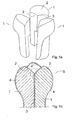
- Figure 1a shows three submoulds 1, each comprising one upper surface 2 and two contact surfaces 3, which submoulds are each separately provided with a fibre layer by means of an electrospinning process.
- Said three submoulds 1 are so constructed that they substantially exclusively comprise convex surfaces besides the usual flat surfaces. It should be understood that the submould 1 does not have any concave surfaces, so that said electrospinning will lead to a uniform fibre layer.
- the submoulds 1 are configured to fit together to form the mould.
- Figure 1b is a sectional view of the three submoulds 1 of figure 1a , showing the submoulds after a fibre layer 4 has been applied to each of the individual submoulds 1.
- the submoulds 1 have subsequently been combined into an assembly 5 by placing the contact surfaces 3 into abutment with each other.
- the part 6 is called the co-optation surface, which is very important in obtaining a properly functioning artificial heart valve. The fact is that such a co-optation surface ensures that the membranes will correctly butt together after the incubation of the preform with human or animal cells so as to obtain the final biological heart valve.
- co-optation surface Since a certain degree of shrinkage of the preform may occur during incubation, it is important that an extra edge (the co-optation surface) is present on the membranes, so that said co-optation surfaces 6 can prevent openings being formed between the membranes when shrinkage occurs, which openings might lead to a leaking heart valve. Such a co-optation surface is not obtained if a single mould for a heart valve is used instead of three submoulds 1 according to the present invention.
- Figure 2a shows the assembly 5 of the submoulds 1 provided with a fibre layer (not shown).
- the assembly 5 is held together by means of a ring construction 7, but it is also possible to use other, conventional methods, of course.
- a complementary submould 8 is shown, which can be placed on the end of the assembly 5 with a close and precise fit.
- the entire mould of the heart valve as shown in figure 2b consists of the assembly 5 of thee submoulds 1 provided with a fibre layer, a ring construction 7 and the submould 8.
- the entire mould will be provided with a fibre layer 9 by electrospinning.
- Figure 2c is a sectional view of the mould after step c), showing submoulds 1,8 with upper surfaces 2 and fibre layers 4,9.
- the figure furthermore shows the co-optation surface 6, which forms part of the fibre layer 4, membranes 10, likewise forming part of the fibre layer 4, which membranes 10 are formed on the upper surfaces 2 of the submoulds 1.
- Figures 3a and 3b are views of the preform thus obtained after the submoulds 1,8 have been removed. Said submoulds can be carefully removed from the fibre layer(s) one by one. Said removal may take place by hand, for example. In addition, part of the fibre layers 4 on the internal contact surfaces 3 is removed, with the exception of the co-optation surface 6, which is maintained.
- Figure 3a is a top plan view and figure 3b is a side view of the preform after the submoulds 1,8 have been removed, showing the membranes 10, the fibre layer 4 (full line) and the fibre layer 9 (dotted line), whilst figure 3b also shows the co-optation surface 6.
- the present invention has this advantage that a fibre-like preform in the form of a heart valve can be obtained, which preform comprises biologically decomposable components.
- the obtained fibre-like preform according to the present invention can be incubated with human or animal cells, which are able to grow in the open fibre-like structure.
- the present fibre-like preform is transferred to a container in which a usual cell growth medium is present, to which human or animal cells are subsequently added. Then the whole is cultured for a specific period of time under standard culturing conditions. In this way an artificial implant based on the present fibre-like preform provided with human or animal tissue is obtained.
- the implant thus obtained can be implanted into a human or animal body.
- the preform will partially or entirely decompose during the culturing of human or animal tissue, but there is also a possibility of the decomposition of the preform continuing or starting after implantation.
- a biologically decomposable or absorbable material for the preform, so that the preform will have decomposed substantially completely after some time and have been replaced by natural tissue, so that a fully natural implant will be present in the body, in contrast to the metal heart valves according to the prior art.
- Another embodiment of the present invention relates to the use of the present preform as a substrate for connecting one or more blood vessels, as shown in figure 4 .
- the present preform is a substrate for connecting one or more blood vessels, as shown in figure 4 .
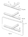
- Figure 4a shows a mould of a T-piece 14 provided with two branches 12,13 for joining two blood vessels.
- Figure 4b shows a submould 14 which, in combination with the mirror image thereof (not shown), forms the complete mould for the T-piece.
- the submould 14 does not comprise any concave surfaces, so that the electrospinning process will provide a uniform fibre layer.
- the two submoulds 14 are separately provided with a fibre layer by electrospinning, and subsequently the two submoulds provided with the fibre layer are joined together, after which the submoulds thus joined together are bonded to each other, for example by means of tubes previously formed by electrospinning or by providing an extra fibre layer by electrospinning.
- FIG 4c An alternative to the above geometry of the submould 14 is shown in figure 4c , in which the submould 17 consists of a flat plate 15 with the same geometric figure 16 as shown in figure 4b 14 present thereon.
- This mould will provide a satisfactory distribution of the fibres.
- the fibre layer can be removed from the plate 15 along the lines of the geometric figure 16, and subsequently the final mould as shown in figure 4a can be formed in the same manner as described above by bonding the fibre layers of the two submoulds together.
- a preform for a T-connection 11 according to the invention obtained in this manner can be used for growing human or animal tissue thereon and be used for implantation in a comparable manner as described above with regard to heart valves.
- the present invention has been explained on the basis of two preferred embodiments, it is also possible to use the present invention for producing other preforms to be used in the production of implants for other parts of the body, such as other valves in the heart or blood vessels, or parts of joints, for example a kneecap, and the like.
Landscapes
- Health & Medical Sciences (AREA)
- Engineering & Computer Science (AREA)
- Life Sciences & Earth Sciences (AREA)
- Biomedical Technology (AREA)
- Cardiology (AREA)
- Veterinary Medicine (AREA)
- Animal Behavior & Ethology (AREA)
- General Health & Medical Sciences (AREA)
- Public Health (AREA)
- Heart & Thoracic Surgery (AREA)
- Vascular Medicine (AREA)
- Textile Engineering (AREA)
- Transplantation (AREA)
- Oral & Maxillofacial Surgery (AREA)
- Surgery (AREA)
- Nuclear Medicine, Radiotherapy & Molecular Imaging (AREA)
- Medical Informatics (AREA)
- Molecular Biology (AREA)
- Manufacturing & Machinery (AREA)
- Pulmonology (AREA)
- Gastroenterology & Hepatology (AREA)
- Epidemiology (AREA)
- Prostheses (AREA)
- Materials For Medical Uses (AREA)
- Micro-Organisms Or Cultivation Processes Thereof (AREA)
Abstract
Description
- The present invention relates to a method for producing a preform by means of an electrospinning process. The present invention also relates to the use of a preform obtained in accordance with the present method, as well as to a method for growing human or animal tissue on a substrate.
-
US patent application No. 2002/0173213 discloses a biologically decomposable or absorbable fibre-like object produced by electrospinning. Such a method can only be used for producing substantially flat objects, such as membranes, whereas it is precisely three-dimensional preforms produced by electrospinning that are in great demand. - Consequently it is an object of the present invention to provide a method for producing a preform by electrospinning, from which preform three-dimensional objects can be made.
- Another object of the present invention is to provide a preform that can be used as a substrate for growing human or animal tissue thereon.
- Yet another object of the present invention is to provide a substrate for an artificial implant, in particular for a heart valve or a T-connection for blood vessels.
- One or more of the above objects can be accomplished by using the method as referred to in the preamble, which is characterized by the following steps:
- a) providing a mould made up of at least two submoulds, which submoulds substantially exclusively comprise convex surfaces;
- b) applying at least one fibre layer to the surface of at least one of the submoulds of step a) by electrospinning;
- c) combining at least one submould of step a) and at least one submould of step b);
- d) applying at least one fibre layer to the surface of the assembly of step c) by electrospinning to obtain the preform.
- The advantage of the present method is that it is possible to obtain a preform having any desired three-dimensional shape, using an electrospinning process, by converting the intended three-dimensional shape into a mould, which mould is subdivided into a number of submoulds. Said submoulds have a spatial configuration such that, besides the usual flat parts, they substantially exclusively comprise convex surfaces.
- The present inventors have found that when a fibre layer is applied to a target having a complex three-dimensional shape, viz. convex, concave and flat parts, by means of an electrospinning process, problems occur in the forming of the fibre layer, since it appears not be possible to form a uniform fibre layer because extra fibres are formed between the concave edges of the mould. Thus it is difficult to provide such concave surfaces with a uniform fibre layer, which uniform fibre layer is highly desirable in practice.
- The aforesaid problem has been solved by the steps a)-d) of the present method, in which the very presence of concave surfaces is avoided by subdividing the mould into a number of submoulds, which submoulds are so constructed that the submoulds do not have any concave shapes any more but substantially exclusively comprise convex surfaces besides the usual flat parts.
- The various submoulds of which the mould is built up are so constructed that they can be combined to form the mould. The submoulds have one or more surfaces that are contiguous to one or more surfaces of the other submoulds, so that said submoulds fit together so as to jointly form the mould.
- Since the preforms that are used in practice frequently have concave as well as convex surfaces, it has not been possible so far to produce such complex three-dimensional preforms provided with a uniform fibre layer by coating the mould by means of an electrospinning process.
- The present inventors have found, however, that it is possible to obtain the desired preforms by subdividing the mould into a number of submoulds, which submoulds each mainly comprise convex surfaces besides the usual flat parts that are already present. Subsequently, said submoulds can be separately provided with fibre layers in one or more steps, after which the submoulds provided with fibre layers can be joined together and as a whole be provided with an additional fibre layer so as to strengthen the whole.
- The submoulds are made of a material that is suitable for use with electrospinning, such as a metal. Also other suitable materials can be used, however.
- The submoulds may be solid or partially hollow. If the submoulds are partially hollow, they may have a closed exterior surface. The submoulds or the mould may be provided with one or more openings, in which openings holders can be fitted, for example, which holders can be used for correctly positioning the submoulds or the mould during the electrospinning process.
- The fibre layer(s) is (are) applied to the surface of the submould/mould, which surface is understood to be the exterior surface of the submould/mould. It is preferred to provide a large part of the submould/mould with at least one fibre layer. It is also possible, however, to provide only part of the surface of the submould/mould with at least one fibre layer. Thus it is possible, for example, not to provide the part of the submould/mould that comprises the holder and/or the part that is used for positioning the submould/mould during the electrospinning process with at least one fibre layer.
- In a specific embodiment of the present invention, at least two fibre layers are applied in step b), viz. first a fibre layer V and subsequently a fibre layer W, with the fibre layer V and the fibre layer W having mutually different biological decomposition rates. Said decomposition rate can be measured in accordance with standard methods, for example, which methods will not be explained in more detail herein.
- Preferably, the biological decomposition of the fibre layer V takes place more rapidly than that of the fibre layer W. In this way the outer layer W of the common fibre layer provides the required strength, whilst the inner fibre layer V can be substituted for natural tissue.
- According to another preferred embodiment, a fibre layer N is used in step b) and a fibre layer M is used in step d), with the fibre layer M being biologically decomposed more quickly than the fibre layer N. In this case, too, the fibre layer N functions to provide stability, whilst the fibre layer M, which is applied as the outer layer for keeping the individual fibre layers of the submoulds together, will decompose more rapidly.
- In yet another embodiment of the present invention , more than two fibre layers are provided, which layers can all be individually selected from the fibre layers V, W, N and M.
- Any fibre material that can be processed by electrospinning can be used as the material for the fibre layer. It is possible, for example, to use polymeric materials, in particular biologically compatible polymeric materials, as the fibre material.
- Another especially preferred embodiment relates to the use of a fibre layer comprising fibres composed of at least two components, wherein the various components have mutually different biological decomposition rates. The fibre consists of sequentially arranged component a and component b, for example, so that a fibre exhibiting a repetitive composition -a-b-a-b-a-b- is obtained. When such a fibre layer is used, one of the two components will decompose after some time, so that a collection of short fibres remains, viz. the fibres of the component having the slower decomposition rate. The short fibres, which are still present, contribute to the mechanical strength of the newly formed natural tissue, whilst the tissue can grow, which is not possible when a fibre layer that only consists of a slowly decomposing component is produced.
- An advantage of the use of a fibre layer consisting of fibres that are composed of two components is the fact that when a preform made of such fibres is used for implantation into young patients, no subsequent surgery is required for exchanging the implant for a larger implant. After all, the implant produced in accordance with the present invention can grow with the patient.
- The present invention also relates to the use of a preform obtained with the present method as a substrate for growing human or animal tissue thereon. The fibre layer that has been applied by electrospinning is a porous network on which cells can grow. Subsequently, the substrate with the cells that have grown thereon can be implanted at the intended position in the body. A number of preferred embodiments are defined in the subclaims and will be explained in more detail hereinafter.
- The present invention furthermore relates to a method for growing human or animal tissue on a substrate, wherein the present preform is used as the substrate. In this way the preform obtained by electrospinning can be provided with a layer of human or animal tissue. Thus, an implant that can be used for implantation into a human or animal body can be obtained through incubation with human or animal cells. Such incubation can be carried out in a bioreactor, for example, in which a specific substrate solution is present, in which substrate solution the cells to be grown are present. Said incubation can be carried out under suitable conditions of temperature, time, pH and the like so as to optimise the cell growth. This will be explained in more detail hereinafter.
- The present invention will now be explained in more detail by means of a description of a number of preferred embodiments, in which reference is made to the accompanying drawings. The present invention is not limited to such specific embodiments, however.
-
-
Figure 1a shows three submoulds of a mould for an artificial, three-membrane heart valve.Figure 1b is a sectional view of an assembly of the submoulds offigure 1a , which have been provided with a fibre layer by electrospinning. -
Figure 2a shows an assembly of the three submoulds offigure 1a and a complementary submould for obtaining a complete heart valve, whilstfigure 2b is a sectional view of the submoulds offigure 2a slid one into another.Figure 2c is a sectional view of the entire mould for the heart valve comprising fibre layers obtained after electrospinning. -
Figures 3a and 3b are a top plan view and a side view, respectively, of a preform according to the present invention obtained by using the mould offigures 2a-2c . -
Figure 4a shows a mould according to another embodiment of the present invention, a T-piece for connecting two or more blood vessels.Figures 4b and 4c show two possible embodiments of a submould. - The present invention will now be explained in more detail with reference to the drawings, which show especially preferred embodiments of the present invention. A preform is made, among other things, which preform functions as a mould for a heart valve (
figures 1-3 ). The drawings show a mould for a heart valve comprising three membranes; according to the invention, however, also other types of valves comprising more or fewer membranes can be produced. -
Figure 1a shows threesubmoulds 1, each comprising oneupper surface 2 and twocontact surfaces 3, which submoulds are each separately provided with a fibre layer by means of an electrospinning process. Said threesubmoulds 1 are so constructed that they substantially exclusively comprise convex surfaces besides the usual flat surfaces. It should be understood that thesubmould 1 does not have any concave surfaces, so that said electrospinning will lead to a uniform fibre layer. Thesubmoulds 1 are configured to fit together to form the mould. -
Figure 1b is a sectional view of the threesubmoulds 1 offigure 1a , showing the submoulds after afibre layer 4 has been applied to each of theindividual submoulds 1. Thesubmoulds 1 have subsequently been combined into anassembly 5 by placing the contact surfaces 3 into abutment with each other. Thepart 6 is called the co-optation surface, which is very important in obtaining a properly functioning artificial heart valve. The fact is that such a co-optation surface ensures that the membranes will correctly butt together after the incubation of the preform with human or animal cells so as to obtain the final biological heart valve. Since a certain degree of shrinkage of the preform may occur during incubation, it is important that an extra edge (the co-optation surface) is present on the membranes, so that said co-optation surfaces 6 can prevent openings being formed between the membranes when shrinkage occurs, which openings might lead to a leaking heart valve. Such a co-optation surface is not obtained if a single mould for a heart valve is used instead of threesubmoulds 1 according to the present invention. -
Figure 2a shows theassembly 5 of thesubmoulds 1 provided with a fibre layer (not shown). Theassembly 5 is held together by means of aring construction 7, but it is also possible to use other, conventional methods, of course. Furthermore, acomplementary submould 8 is shown, which can be placed on the end of theassembly 5 with a close and precise fit. - The entire mould of the heart valve as shown in
figure 2b consists of theassembly 5 ofthee submoulds 1 provided with a fibre layer, aring construction 7 and thesubmould 8. In a next step (d) of the method, the entire mould will be provided with afibre layer 9 by electrospinning. -
Figure 2c is a sectional view of the mould after step c), showing submoulds 1,8 withupper surfaces 2 andfibre layers co-optation surface 6, which forms part of thefibre layer 4,membranes 10, likewise forming part of thefibre layer 4, which membranes 10 are formed on theupper surfaces 2 of thesubmoulds 1. -
Figures 3a and 3b are views of the preform thus obtained after thesubmoulds internal contact surfaces 3 is removed, with the exception of theco-optation surface 6, which is maintained.Figure 3a is a top plan view andfigure 3b is a side view of the preform after thesubmoulds membranes 10, the fibre layer 4 (full line) and the fibre layer 9 (dotted line), whilstfigure 3b also shows theco-optation surface 6. - Although the production of artificial heart valves has already been extensively described in the literature, with
US patent application No. 2002/0173213 disclosing the use of artificial heart valves made of metal alloys, such heart valves have this drawback that a material that does not naturally occur in the body (metal alloy) is implanted into the body, where it will permanently remain. - Consequently, the present invention has this advantage that a fibre-like preform in the form of a heart valve can be obtained, which preform comprises biologically decomposable components.
- The obtained fibre-like preform according to the present invention can be incubated with human or animal cells, which are able to grow in the open fibre-like structure. To this end, the present fibre-like preform is transferred to a container in which a usual cell growth medium is present, to which human or animal cells are subsequently added. Then the whole is cultured for a specific period of time under standard culturing conditions. In this way an artificial implant based on the present fibre-like preform provided with human or animal tissue is obtained.
- The implant thus obtained can be implanted into a human or animal body. There is a possibility that the preform will partially or entirely decompose during the culturing of human or animal tissue, but there is also a possibility of the decomposition of the preform continuing or starting after implantation. Thus it is preferable according to the invention to use a biologically decomposable or absorbable material for the preform, so that the preform will have decomposed substantially completely after some time and have been replaced by natural tissue, so that a fully natural implant will be present in the body, in contrast to the metal heart valves according to the prior art.
- Another embodiment of the present invention relates to the use of the present preform as a substrate for connecting one or more blood vessels, as shown in
figure 4 . When one or more blood vessels are connected by suturing, leakage frequently occurs, because this is a complex procedure and the blood vessels are so small and circular in shape that suturing is problematic. Consequently, there is a need for a T-piece that can be used for connecting two or more blood vessels. -
Figure 4a shows a mould of a T-piece 14 provided with twobranches -
Figure 4b shows asubmould 14 which, in combination with the mirror image thereof (not shown), forms the complete mould for the T-piece. It should be understood that thesubmould 14 does not comprise any concave surfaces, so that the electrospinning process will provide a uniform fibre layer. The two submoulds 14 are separately provided with a fibre layer by electrospinning, and subsequently the two submoulds provided with the fibre layer are joined together, after which the submoulds thus joined together are bonded to each other, for example by means of tubes previously formed by electrospinning or by providing an extra fibre layer by electrospinning. - An alternative to the above geometry of the
submould 14 is shown infigure 4c , in which thesubmould 17 consists of aflat plate 15 with the same geometric figure 16 as shown infigure 4b submould 17 according tofigure 4c by electrospinning, the fibre layer can be removed from theplate 15 along the lines of the geometric figure 16, and subsequently the final mould as shown infigure 4a can be formed in the same manner as described above by bonding the fibre layers of the two submoulds together. - A preform for a T-
connection 11 according to the invention obtained in this manner can be used for growing human or animal tissue thereon and be used for implantation in a comparable manner as described above with regard to heart valves. - Although the present invention has been explained on the basis of two preferred embodiments, it is also possible to use the present invention for producing other preforms to be used in the production of implants for other parts of the body, such as other valves in the heart or blood vessels, or parts of joints, for example a kneecap, and the like.
Claims (10)
- A method for producing a preform by means of an electrospinning process, characterized by the steps of:a) providing a mould made up of at least two submoulds, which submoulds substantially exclusively comprise convex surfaces;b) applying at least one fibre layer to the surface of at least one of the submoulds of step a) by electrospinning;c) combining at least one submould of step a) and at least one submould of step b);d) applying at least one fibre layer to the surface of the assembly of step c) by electrospinning to obtain the preform.
- A method according to claim 1, characterized in that step b) comprises two substeps:b1) applying a fibre layer V to the surface of at least one of the submoulds of step a) by electrospinning;b2) applying a fibre layer W to the surface of the submould of step b1) provided with the fibre layer V by electrospinning.
- A method according to claim 2, characterized in that the biological decomposition of the fibre layer V takes place more rapidly than that of the fibre layer W.
- A method according to claim 1, characterized in that a fibre layer N is used in step b) and a fibre layer M is used in step d).
- A method according to claim 4, characterized in that the biological decomposition of the fibre layer M takes place more rapidly than that of the fibre layer N.
- A method according to any one or more of the preceding claims, characterized in that the fibre layer comprises fibres, which fibres are composed of at least two components, which components have mutually different biological decomposition rates.
- Use of a preform obtainable by using one or more of the preceding methods as a substrate for growing human or animal tissue thereon.
- Use according to claim 7, characterized in that said preform is a substrate for a heart valve.
- Use according to claim 7, characterized in that said preform is a substrate for connecting one or more blood vessels.
- A method for growing tissue on a substrate, comprising the step of incubating a preform obtainable in accordance with one or more of the methods according to claims 1-7 with human or animal cells.
Applications Claiming Priority (2)
| Application Number | Priority Date | Filing Date | Title |
|---|---|---|---|
| NL1026076A NL1026076C2 (en) | 2004-04-29 | 2004-04-29 | Molded part manufactured by means of electro-spinning and a method for the manufacture thereof as well as the use of such a molded part. |
| PCT/NL2005/000324 WO2005106090A2 (en) | 2004-04-29 | 2005-04-28 | Preform produced by electrospinning, method for producting the same and use of such a preform |
Publications (2)
| Publication Number | Publication Date |
|---|---|
| EP1740747A2 EP1740747A2 (en) | 2007-01-10 |
| EP1740747B1 true EP1740747B1 (en) | 2012-07-18 |
Family
ID=34973730
Family Applications (1)
| Application Number | Title | Priority Date | Filing Date |
|---|---|---|---|
| EP05740692A Expired - Lifetime EP1740747B1 (en) | 2004-04-29 | 2005-04-28 | Preform produced by electrospinning, method for producing the same and use of such a preform |
Country Status (5)
| Country | Link |
|---|---|
| US (4) | US8551778B2 (en) |
| EP (1) | EP1740747B1 (en) |
| ES (1) | ES2389558T3 (en) |
| NL (1) | NL1026076C2 (en) |
| WO (1) | WO2005106090A2 (en) |
Cited By (15)
| Publication number | Priority date | Publication date | Assignee | Title |
|---|---|---|---|---|
| US10856984B2 (en) | 2017-08-25 | 2020-12-08 | Neovasc Tiara Inc. | Sequentially deployed transcatheter mitral valve prosthesis |
| US10940001B2 (en) | 2012-05-30 | 2021-03-09 | Neovasc Tiara Inc. | Methods and apparatus for loading a prosthesis onto a delivery system |
| US11311376B2 (en) | 2019-06-20 | 2022-04-26 | Neovase Tiara Inc. | Low profile prosthetic mitral valve |
| US11357622B2 (en) | 2016-01-29 | 2022-06-14 | Neovase Tiara Inc. | Prosthetic valve for avoiding obstruction of outflow |
| US11389291B2 (en) | 2013-04-04 | 2022-07-19 | Neovase Tiara Inc. | Methods and apparatus for delivering a prosthetic valve to a beating heart |
| US11413139B2 (en) | 2011-11-23 | 2022-08-16 | Neovasc Tiara Inc. | Sequentially deployed transcatheter mitral valve prosthesis |
| US11419720B2 (en) | 2010-05-05 | 2022-08-23 | Neovasc Tiara Inc. | Transcatheter mitral valve prosthesis |
| US11464631B2 (en) | 2016-11-21 | 2022-10-11 | Neovasc Tiara Inc. | Methods and systems for rapid retraction of a transcatheter heart valve delivery system |
| US11491006B2 (en) | 2019-04-10 | 2022-11-08 | Neovasc Tiara Inc. | Prosthetic valve with natural blood flow |
| US11497602B2 (en) | 2012-02-14 | 2022-11-15 | Neovasc Tiara Inc. | Methods and apparatus for engaging a valve prosthesis with tissue |
| US11602429B2 (en) | 2019-04-01 | 2023-03-14 | Neovasc Tiara Inc. | Controllably deployable prosthetic valve |
| US11737872B2 (en) | 2018-11-08 | 2023-08-29 | Neovasc Tiara Inc. | Ventricular deployment of a transcatheter mitral valve prosthesis |
| US11779742B2 (en) | 2019-05-20 | 2023-10-10 | Neovasc Tiara Inc. | Introducer with hemostasis mechanism |
| US11998447B2 (en) | 2019-03-08 | 2024-06-04 | Neovasc Tiara Inc. | Retrievable prosthesis delivery system |
| US12109111B2 (en) | 2015-12-15 | 2024-10-08 | Neovasc Tiara Inc. | Transseptal delivery system |
Families Citing this family (20)
| Publication number | Priority date | Publication date | Assignee | Title |
|---|---|---|---|---|
| EP1862188B1 (en) * | 2006-06-02 | 2018-02-28 | Eidgenössische Technische Hochschule Zürich | Porous membrane comprising a biocompatible block-copolymer |
| EP2431061A3 (en) * | 2006-06-09 | 2012-08-08 | Eidgenössische Technische Hochschule Zürich | Valve model for producing scaffolds for artificial heart valves and vascular structures |
| US20150265744A1 (en) * | 2008-10-09 | 2015-09-24 | Technische Universiteit Eindhoven | Multilayer preform obtained by electro-spinning, method for producing a preform as well as use thereof |
| NL1036038C (en) * | 2008-10-09 | 2010-04-14 | Univ Eindhoven Tech | Multilayer preform obtained by electro-spinning, method for producing a preform as well as use thereof. |
| JP5676115B2 (en) * | 2009-07-02 | 2015-02-25 | 独立行政法人国立循環器病研究センター | Artificial blood vessel with valve, columnar core substrate for artificial blood vessel with valve, and method for producing artificial blood vessel with valve |
| US8685082B2 (en) * | 2010-11-18 | 2014-04-01 | National Cerebral And Cardiovascular Center | Base material for forming valved lumen shape tissue, method for producing valved lumen shape tissue, and valved artificial blood vessel |
| CN103596751A (en) * | 2011-04-06 | 2014-02-19 | 约翰逊控制技术公司 | Seat cushion having an electrospun nonwoven polymer layer |
| GB201113060D0 (en) | 2011-07-29 | 2011-09-14 | Univ Ulster | Tissue scaffold |
| NL2009145C2 (en) | 2012-07-06 | 2014-01-07 | Xeltis B V | Implant. |
| US20140207248A1 (en) * | 2013-01-18 | 2014-07-24 | The Trustees Of The Stevens Institute Of Technology | Hierarchical multiscale fibrous scaffold via 3-d electrostatic deposition prototyping and conventional electrospinning |
| WO2015044190A1 (en) | 2013-09-27 | 2015-04-02 | Technische Universiteit Eindhoven | Controlling tissue engineered heart valve geometry by using predefined inserts during culture |
| EP3096713B1 (en) * | 2014-01-23 | 2022-09-21 | President and Fellows of Harvard College | Engineered polymeric valves, tubular structures and sheets |
| US10583004B2 (en) | 2015-02-27 | 2020-03-10 | University of Pittsburgh — Of the Commonwealth System of Higher Education | Retrievable self-expanding non-thrombogenic low-profile percutaneous atrioventricular valve prosthesis |
| US11129711B2 (en) | 2015-02-27 | 2021-09-28 | University of Pittsburgh—of the Commonwealth System of Higher Education | Double component mandrel for electrospun stentless, multi-leaflet valve fabrication |
| WO2017083381A1 (en) * | 2015-11-09 | 2017-05-18 | President And Fellows Of Harvard College | Engineered polymeric valves and systems, methods for generating the same, and uses of the same |
| WO2017162645A1 (en) * | 2016-03-22 | 2017-09-28 | Assistance Publique-Hôpitaux de Paris | Vascular valved prosthesis and manufacturing method |
| US11027332B2 (en) * | 2016-04-15 | 2021-06-08 | United States Of America As Represented By The Administrator Of Nasa | System and method for in-situ characterization and inspection of additive manufacturing deposits using transient infrared thermography |
| CN112469368A (en) | 2018-07-23 | 2021-03-09 | 美敦力公司 | Electrospun medical devices and methods of manufacturing electrospun medical devices |
| JP7689736B2 (en) | 2019-01-14 | 2025-06-09 | プレジデント アンド フェローズ オブ ハーバード カレッジ | Focused Rotary Jet Spinning Devices and Methods of Their Use - Patent application |
| CN112297463B (en) * | 2020-09-08 | 2022-07-22 | 江苏新扬新材料股份有限公司 | Carbon fiber composite piston molding process |
Family Cites Families (17)
| Publication number | Priority date | Publication date | Assignee | Title |
|---|---|---|---|---|
| GB1527592A (en) * | 1974-08-05 | 1978-10-04 | Ici Ltd | Wound dressing |
| GB1530990A (en) * | 1974-08-05 | 1978-11-01 | Ici Ltd | Electrostatically spun tubular product |
| US5855601A (en) | 1996-06-21 | 1999-01-05 | The Trustees Of Columbia University In The City Of New York | Artificial heart valve and method and device for implanting the same |
| US5928281A (en) | 1997-03-27 | 1999-07-27 | Baxter International Inc. | Tissue heart valves |
| EP1221927B1 (en) * | 1999-10-08 | 2010-07-28 | The University of Akron | Electrospun skin masks and uses thereof |
| US6491511B1 (en) * | 1999-10-14 | 2002-12-10 | The International Heart Institute Of Montana Foundation | Mold to form stent-less replacement heart valves from biological membranes |
| US6440164B1 (en) | 1999-10-21 | 2002-08-27 | Scimed Life Systems, Inc. | Implantable prosthetic valve |
| US6458153B1 (en) | 1999-12-31 | 2002-10-01 | Abps Venture One, Ltd. | Endoluminal cardiac and venous valve prostheses and methods of manufacture and delivery thereof |
| US6676698B2 (en) | 2000-06-26 | 2004-01-13 | Rex Medicol, L.P. | Vascular device with valve for approximating vessel wall |
| CA2457162A1 (en) * | 2000-09-01 | 2002-03-07 | Virginia Commonwealth University Intellectual Property Foundation | Electroprocessed fibrin-based matrices and tissues |
| US20020084178A1 (en) * | 2000-12-19 | 2002-07-04 | Nicast Corporation Ltd. | Method and apparatus for manufacturing polymer fiber shells via electrospinning |
| US6685956B2 (en) * | 2001-05-16 | 2004-02-03 | The Research Foundation At State University Of New York | Biodegradable and/or bioabsorbable fibrous articles and methods for using the articles for medical applications |
| US20030100944A1 (en) * | 2001-11-28 | 2003-05-29 | Olga Laksin | Vascular graft having a chemicaly bonded electrospun fibrous layer and method for making same |
| MXPA04011144A (en) | 2002-05-10 | 2005-08-16 | Johnson & Johnson | Method of making a medical device having a thin wall tubular membrane over a structural frame. |
| EP3400908B2 (en) | 2006-05-30 | 2026-04-22 | Cook Medical Technologies LLC | Artificial valve prosthesis |
| HUE047762T2 (en) | 2008-06-06 | 2020-05-28 | Edwards Lifesciences Corp | Low profile transcatheter heart valve |
| US9629715B2 (en) | 2011-07-28 | 2017-04-25 | V-Wave Ltd. | Devices for reducing left atrial pressure having biodegradable constriction, and methods of making and using same |
-
2004
- 2004-04-29 NL NL1026076A patent/NL1026076C2/en not_active IP Right Cessation
-
2005
- 2005-04-28 ES ES05740692T patent/ES2389558T3/en not_active Expired - Lifetime
- 2005-04-28 WO PCT/NL2005/000324 patent/WO2005106090A2/en not_active Ceased
- 2005-04-28 EP EP05740692A patent/EP1740747B1/en not_active Expired - Lifetime
- 2005-04-28 US US11/587,641 patent/US8551778B2/en active Active
-
2013
- 2013-07-17 US US13/943,925 patent/US9272076B2/en active Active
-
2016
- 2016-02-18 US US15/047,348 patent/US9566176B2/en not_active Expired - Lifetime
-
2017
- 2017-01-13 US US15/405,469 patent/US10123890B2/en not_active Expired - Lifetime
Cited By (25)
| Publication number | Priority date | Publication date | Assignee | Title |
|---|---|---|---|---|
| US12611303B2 (en) | 2010-05-05 | 2026-04-28 | Neovasc Tiara Inc. | Transcatheter mitral valve prosthesis |
| US11419720B2 (en) | 2010-05-05 | 2022-08-23 | Neovasc Tiara Inc. | Transcatheter mitral valve prosthesis |
| US11413139B2 (en) | 2011-11-23 | 2022-08-16 | Neovasc Tiara Inc. | Sequentially deployed transcatheter mitral valve prosthesis |
| US12053369B2 (en) | 2011-11-23 | 2024-08-06 | Neovasc Tiara Inc. | Sequentially deployed transcatheter mitral valve prosthesis |
| US12138159B2 (en) | 2012-02-14 | 2024-11-12 | Neovasc Tiara Inc. | Methods and apparatus for engaging a valve prosthesis with tissue |
| US11497602B2 (en) | 2012-02-14 | 2022-11-15 | Neovasc Tiara Inc. | Methods and apparatus for engaging a valve prosthesis with tissue |
| US11617650B2 (en) | 2012-05-30 | 2023-04-04 | Neovasc Tiara Inc. | Methods and apparatus for loading a prosthesis onto a delivery system |
| US10940001B2 (en) | 2012-05-30 | 2021-03-09 | Neovasc Tiara Inc. | Methods and apparatus for loading a prosthesis onto a delivery system |
| US11389294B2 (en) | 2012-05-30 | 2022-07-19 | Neovasc Tiara Inc. | Methods and apparatus for loading a prosthesis onto a delivery system |
| US11389291B2 (en) | 2013-04-04 | 2022-07-19 | Neovase Tiara Inc. | Methods and apparatus for delivering a prosthetic valve to a beating heart |
| US12109111B2 (en) | 2015-12-15 | 2024-10-08 | Neovasc Tiara Inc. | Transseptal delivery system |
| US12193932B2 (en) | 2016-01-29 | 2025-01-14 | Neovasc Tiara Inc. | Prosthetic valve for avoiding obstruction of outflow |
| US11357622B2 (en) | 2016-01-29 | 2022-06-14 | Neovase Tiara Inc. | Prosthetic valve for avoiding obstruction of outflow |
| US11464631B2 (en) | 2016-11-21 | 2022-10-11 | Neovasc Tiara Inc. | Methods and systems for rapid retraction of a transcatheter heart valve delivery system |
| US12201524B2 (en) | 2016-11-21 | 2025-01-21 | Neovasc Tiara Inc. | Methods and systems for rapid retraction of a transcatheter heart valve delivery system |
| US11793640B2 (en) | 2017-08-25 | 2023-10-24 | Neovasc Tiara Inc. | Sequentially deployed transcatheter mitral valve prosthesis |
| US10856984B2 (en) | 2017-08-25 | 2020-12-08 | Neovasc Tiara Inc. | Sequentially deployed transcatheter mitral valve prosthesis |
| US11737872B2 (en) | 2018-11-08 | 2023-08-29 | Neovasc Tiara Inc. | Ventricular deployment of a transcatheter mitral valve prosthesis |
| US11998447B2 (en) | 2019-03-08 | 2024-06-04 | Neovasc Tiara Inc. | Retrievable prosthesis delivery system |
| US11602429B2 (en) | 2019-04-01 | 2023-03-14 | Neovasc Tiara Inc. | Controllably deployable prosthetic valve |
| US12036117B2 (en) | 2019-04-10 | 2024-07-16 | Neovasc Tiara Inc. | Prosthetic valve with natural blood flow |
| US11491006B2 (en) | 2019-04-10 | 2022-11-08 | Neovasc Tiara Inc. | Prosthetic valve with natural blood flow |
| US11779742B2 (en) | 2019-05-20 | 2023-10-10 | Neovasc Tiara Inc. | Introducer with hemostasis mechanism |
| US11931254B2 (en) | 2019-06-20 | 2024-03-19 | Neovasc Tiara Inc. | Low profile prosthetic mitral valve |
| US11311376B2 (en) | 2019-06-20 | 2022-04-26 | Neovase Tiara Inc. | Low profile prosthetic mitral valve |
Also Published As
| Publication number | Publication date |
|---|---|
| US10123890B2 (en) | 2018-11-13 |
| WO2005106090A3 (en) | 2006-01-19 |
| US20080131965A1 (en) | 2008-06-05 |
| US20170202689A1 (en) | 2017-07-20 |
| ES2389558T3 (en) | 2012-10-29 |
| NL1026076C2 (en) | 2005-11-01 |
| WO2005106090A2 (en) | 2005-11-10 |
| US8551778B2 (en) | 2013-10-08 |
| US9566176B2 (en) | 2017-02-14 |
| US20160220398A1 (en) | 2016-08-04 |
| US9272076B2 (en) | 2016-03-01 |
| EP1740747A2 (en) | 2007-01-10 |
| US20140025156A1 (en) | 2014-01-23 |
Similar Documents
| Publication | Publication Date | Title |
|---|---|---|
| US10123890B2 (en) | Preform produced by electrospinning, method for producing the same and use of such a preform | |
| US6143293A (en) | Assembled scaffolds for three dimensional cell culturing and tissue generation | |
| US7744526B2 (en) | Bioreactor for the manufacture of tissue engineered blood vessels | |
| EP2334857B1 (en) | Multilayer preform obtained by electro-spinning, method for producing a preform as well as use thereof. | |
| EP2931179B1 (en) | Process for growing a heart valve in three-dimensions | |
| EP1994089B1 (en) | Process for the production of a tubular cellulose body | |
| US20150265744A1 (en) | Multilayer preform obtained by electro-spinning, method for producing a preform as well as use thereof | |
| CN104146793B (en) | A kind of manufacture method with biological activity organ | |
| US8993324B2 (en) | Process and support structure for the cultivation of living cells | |
| AU2009257557B2 (en) | Tissue retaining system | |
| WO2022064125A1 (en) | Process for manufacturing a biological valve using bioprinting | |
| CN111359018B (en) | Double-layer anti-seepage dura mater repairing sheet and preparation method thereof | |
| CN119587225B (en) | Porous dual-gradient bone scaffold with shape memory effect and preparation method thereof | |
| CN202223387U (en) | Controllable vascularization artificial bone graft |
Legal Events
| Date | Code | Title | Description |
|---|---|---|---|
| PUAI | Public reference made under article 153(3) epc to a published international application that has entered the european phase |
Free format text: ORIGINAL CODE: 0009012 |
|
| 17P | Request for examination filed |
Effective date: 20061024 |
|
| AK | Designated contracting states |
Kind code of ref document: A2 Designated state(s): AT BE BG CH CY CZ DE DK EE ES FI FR GB GR HU IE IS IT LI LT LU MC NL PL PT RO SE SI SK TR |
|
| DAX | Request for extension of the european patent (deleted) | ||
| 17Q | First examination report despatched |
Effective date: 20100923 |
|
| REG | Reference to a national code |
Ref country code: DE Ref legal event code: R079 Ref document number: 602005035217 Country of ref document: DE Free format text: PREVIOUS MAIN CLASS: D04H0001420000 Ipc: A61F0002020000 |
|
| RIC1 | Information provided on ipc code assigned before grant |
Ipc: A61F 2/24 20060101ALI20111219BHEP Ipc: D04H 13/00 20060101ALI20111219BHEP Ipc: D04H 1/42 20120101ALI20111219BHEP Ipc: A61B 17/11 20060101ALI20111219BHEP Ipc: A61L 27/00 20060101ALI20111219BHEP Ipc: A61F 2/02 20060101AFI20111219BHEP Ipc: D04H 1/728 20120101ALI20111219BHEP |
|
| GRAP | Despatch of communication of intention to grant a patent |
Free format text: ORIGINAL CODE: EPIDOSNIGR1 |
|
| GRAS | Grant fee paid |
Free format text: ORIGINAL CODE: EPIDOSNIGR3 |
|
| GRAA | (expected) grant |
Free format text: ORIGINAL CODE: 0009210 |
|
| AK | Designated contracting states |
Kind code of ref document: B1 Designated state(s): AT BE BG CH CY CZ DE DK EE ES FI FR GB GR HU IE IS IT LI LT LU MC NL PL PT RO SE SI SK TR |
|
| REG | Reference to a national code |
Ref country code: GB Ref legal event code: FG4D |
|
| REG | Reference to a national code |
Ref country code: CH Ref legal event code: EP |
|
| REG | Reference to a national code |
Ref country code: IE Ref legal event code: FG4D Ref country code: AT Ref legal event code: REF Ref document number: 566740 Country of ref document: AT Kind code of ref document: T Effective date: 20120815 |
|
| REG | Reference to a national code |
Ref country code: DE Ref legal event code: R096 Ref document number: 602005035217 Country of ref document: DE Effective date: 20120913 |
|
| REG | Reference to a national code |
Ref country code: CH Ref legal event code: NV Representative=s name: DR. LUSUARDI AG |
|
| REG | Reference to a national code |
Ref country code: ES Ref legal event code: FG2A Ref document number: 2389558 Country of ref document: ES Kind code of ref document: T3 Effective date: 20121029 |
|
| REG | Reference to a national code |
Ref country code: NL Ref legal event code: T3 |
|
| REG | Reference to a national code |
Ref country code: AT Ref legal event code: MK05 Ref document number: 566740 Country of ref document: AT Kind code of ref document: T Effective date: 20120718 |
|
| REG | Reference to a national code |
Ref country code: LT Ref legal event code: MG4D Effective date: 20120718 |
|
| PG25 | Lapsed in a contracting state [announced via postgrant information from national office to epo] |
Ref country code: FI Free format text: LAPSE BECAUSE OF FAILURE TO SUBMIT A TRANSLATION OF THE DESCRIPTION OR TO PAY THE FEE WITHIN THE PRESCRIBED TIME-LIMIT Effective date: 20120718 Ref country code: IS Free format text: LAPSE BECAUSE OF FAILURE TO SUBMIT A TRANSLATION OF THE DESCRIPTION OR TO PAY THE FEE WITHIN THE PRESCRIBED TIME-LIMIT Effective date: 20121118 Ref country code: AT Free format text: LAPSE BECAUSE OF FAILURE TO SUBMIT A TRANSLATION OF THE DESCRIPTION OR TO PAY THE FEE WITHIN THE PRESCRIBED TIME-LIMIT Effective date: 20120718 Ref country code: CY Free format text: LAPSE BECAUSE OF FAILURE TO SUBMIT A TRANSLATION OF THE DESCRIPTION OR TO PAY THE FEE WITHIN THE PRESCRIBED TIME-LIMIT Effective date: 20120718 Ref country code: LT Free format text: LAPSE BECAUSE OF FAILURE TO SUBMIT A TRANSLATION OF THE DESCRIPTION OR TO PAY THE FEE WITHIN THE PRESCRIBED TIME-LIMIT Effective date: 20120718 |
|
| PG25 | Lapsed in a contracting state [announced via postgrant information from national office to epo] |
Ref country code: SI Free format text: LAPSE BECAUSE OF FAILURE TO SUBMIT A TRANSLATION OF THE DESCRIPTION OR TO PAY THE FEE WITHIN THE PRESCRIBED TIME-LIMIT Effective date: 20120718 Ref country code: SE Free format text: LAPSE BECAUSE OF FAILURE TO SUBMIT A TRANSLATION OF THE DESCRIPTION OR TO PAY THE FEE WITHIN THE PRESCRIBED TIME-LIMIT Effective date: 20120718 Ref country code: PT Free format text: LAPSE BECAUSE OF FAILURE TO SUBMIT A TRANSLATION OF THE DESCRIPTION OR TO PAY THE FEE WITHIN THE PRESCRIBED TIME-LIMIT Effective date: 20121119 Ref country code: GR Free format text: LAPSE BECAUSE OF FAILURE TO SUBMIT A TRANSLATION OF THE DESCRIPTION OR TO PAY THE FEE WITHIN THE PRESCRIBED TIME-LIMIT Effective date: 20121019 Ref country code: PL Free format text: LAPSE BECAUSE OF FAILURE TO SUBMIT A TRANSLATION OF THE DESCRIPTION OR TO PAY THE FEE WITHIN THE PRESCRIBED TIME-LIMIT Effective date: 20120718 |
|
| PG25 | Lapsed in a contracting state [announced via postgrant information from national office to epo] |
Ref country code: CZ Free format text: LAPSE BECAUSE OF FAILURE TO SUBMIT A TRANSLATION OF THE DESCRIPTION OR TO PAY THE FEE WITHIN THE PRESCRIBED TIME-LIMIT Effective date: 20120718 Ref country code: RO Free format text: LAPSE BECAUSE OF FAILURE TO SUBMIT A TRANSLATION OF THE DESCRIPTION OR TO PAY THE FEE WITHIN THE PRESCRIBED TIME-LIMIT Effective date: 20120718 Ref country code: DK Free format text: LAPSE BECAUSE OF FAILURE TO SUBMIT A TRANSLATION OF THE DESCRIPTION OR TO PAY THE FEE WITHIN THE PRESCRIBED TIME-LIMIT Effective date: 20120718 Ref country code: EE Free format text: LAPSE BECAUSE OF FAILURE TO SUBMIT A TRANSLATION OF THE DESCRIPTION OR TO PAY THE FEE WITHIN THE PRESCRIBED TIME-LIMIT Effective date: 20120718 |
|
| PLBE | No opposition filed within time limit |
Free format text: ORIGINAL CODE: 0009261 |
|
| STAA | Information on the status of an ep patent application or granted ep patent |
Free format text: STATUS: NO OPPOSITION FILED WITHIN TIME LIMIT |
|
| PG25 | Lapsed in a contracting state [announced via postgrant information from national office to epo] |
Ref country code: SK Free format text: LAPSE BECAUSE OF FAILURE TO SUBMIT A TRANSLATION OF THE DESCRIPTION OR TO PAY THE FEE WITHIN THE PRESCRIBED TIME-LIMIT Effective date: 20120718 |
|
| 26N | No opposition filed |
Effective date: 20130419 |
|
| PG25 | Lapsed in a contracting state [announced via postgrant information from national office to epo] |
Ref country code: BG Free format text: LAPSE BECAUSE OF FAILURE TO SUBMIT A TRANSLATION OF THE DESCRIPTION OR TO PAY THE FEE WITHIN THE PRESCRIBED TIME-LIMIT Effective date: 20121018 |
|
| REG | Reference to a national code |
Ref country code: DE Ref legal event code: R097 Ref document number: 602005035217 Country of ref document: DE Effective date: 20130419 |
|
| PG25 | Lapsed in a contracting state [announced via postgrant information from national office to epo] |
Ref country code: MC Free format text: LAPSE BECAUSE OF FAILURE TO SUBMIT A TRANSLATION OF THE DESCRIPTION OR TO PAY THE FEE WITHIN THE PRESCRIBED TIME-LIMIT Effective date: 20120718 |
|
| PG25 | Lapsed in a contracting state [announced via postgrant information from national office to epo] |
Ref country code: TR Free format text: LAPSE BECAUSE OF FAILURE TO SUBMIT A TRANSLATION OF THE DESCRIPTION OR TO PAY THE FEE WITHIN THE PRESCRIBED TIME-LIMIT Effective date: 20120718 |
|
| PG25 | Lapsed in a contracting state [announced via postgrant information from national office to epo] |
Ref country code: LU Free format text: LAPSE BECAUSE OF NON-PAYMENT OF DUE FEES Effective date: 20130428 Ref country code: HU Free format text: LAPSE BECAUSE OF FAILURE TO SUBMIT A TRANSLATION OF THE DESCRIPTION OR TO PAY THE FEE WITHIN THE PRESCRIBED TIME-LIMIT; INVALID AB INITIO Effective date: 20050428 |
|
| REG | Reference to a national code |
Ref country code: FR Ref legal event code: PLFP Year of fee payment: 12 |
|
| REG | Reference to a national code |
Ref country code: FR Ref legal event code: PLFP Year of fee payment: 13 |
|
| REG | Reference to a national code |
Ref country code: FR Ref legal event code: PLFP Year of fee payment: 14 |
|
| PGFP | Annual fee paid to national office [announced via postgrant information from national office to epo] |
Ref country code: DE Payment date: 20210610 Year of fee payment: 17 Ref country code: FR Payment date: 20210429 Year of fee payment: 17 Ref country code: IT Payment date: 20210409 Year of fee payment: 17 |
|
| PGFP | Annual fee paid to national office [announced via postgrant information from national office to epo] |
Ref country code: CH Payment date: 20210408 Year of fee payment: 17 Ref country code: ES Payment date: 20210504 Year of fee payment: 17 Ref country code: GB Payment date: 20210406 Year of fee payment: 17 Ref country code: IE Payment date: 20210429 Year of fee payment: 17 Ref country code: BE Payment date: 20210408 Year of fee payment: 17 |
|
| PGFP | Annual fee paid to national office [announced via postgrant information from national office to epo] |
Ref country code: NL Payment date: 20210408 Year of fee payment: 17 |
|
| REG | Reference to a national code |
Ref country code: DE Ref legal event code: R119 Ref document number: 602005035217 Country of ref document: DE |
|
| REG | Reference to a national code |
Ref country code: CH Ref legal event code: PL |
|
| REG | Reference to a national code |
Ref country code: NL Ref legal event code: MM Effective date: 20220501 |
|
| GBPC | Gb: european patent ceased through non-payment of renewal fee |
Effective date: 20220428 |
|
| REG | Reference to a national code |
Ref country code: BE Ref legal event code: MM Effective date: 20220430 |
|
| PG25 | Lapsed in a contracting state [announced via postgrant information from national office to epo] |
Ref country code: NL Free format text: LAPSE BECAUSE OF NON-PAYMENT OF DUE FEES Effective date: 20220501 Ref country code: LI Free format text: LAPSE BECAUSE OF NON-PAYMENT OF DUE FEES Effective date: 20220430 Ref country code: GB Free format text: LAPSE BECAUSE OF NON-PAYMENT OF DUE FEES Effective date: 20220428 Ref country code: FR Free format text: LAPSE BECAUSE OF NON-PAYMENT OF DUE FEES Effective date: 20220430 Ref country code: DE Free format text: LAPSE BECAUSE OF NON-PAYMENT OF DUE FEES Effective date: 20221103 Ref country code: CH Free format text: LAPSE BECAUSE OF NON-PAYMENT OF DUE FEES Effective date: 20220430 |
|
| PG25 | Lapsed in a contracting state [announced via postgrant information from national office to epo] |
Ref country code: BE Free format text: LAPSE BECAUSE OF NON-PAYMENT OF DUE FEES Effective date: 20220430 |
|
| PG25 | Lapsed in a contracting state [announced via postgrant information from national office to epo] |
Ref country code: IE Free format text: LAPSE BECAUSE OF NON-PAYMENT OF DUE FEES Effective date: 20220428 |
|
| REG | Reference to a national code |
Ref country code: ES Ref legal event code: FD2A Effective date: 20230530 |
|
| PG25 | Lapsed in a contracting state [announced via postgrant information from national office to epo] |
Ref country code: IT Free format text: LAPSE BECAUSE OF NON-PAYMENT OF DUE FEES Effective date: 20220428 |
|
| PG25 | Lapsed in a contracting state [announced via postgrant information from national office to epo] |
Ref country code: ES Free format text: LAPSE BECAUSE OF NON-PAYMENT OF DUE FEES Effective date: 20220429 |